

Page 1

¡Store in a manner that permits use anytime.
,,,,,,,,,,,,,,,,,,,,,,,,,,,,,,,,,,,,,,,,,,,,,,,,,,,,,,,,,,,,,,,,,,,,,,,,,,,,,,,,,,,,,,,,,
,
,,,,,,,,,,,,,,,,,,,,,,,,,,,,,,,,,,,,,,,,,,,,,,,,,,,,,,,,,,,,,,,,,,,,,,,,,,,,,,,,,,,,,,,,,
,
,,,,,,,,,,,,,,,,,,,,,,,,,,,,,,,,,,,,,,,,,,,,,,,,,,,,,,,,,,,,,,,,,,,,,,,,,,,,,,,,,,,,,,,,,
,
,,,,,,,,,,,,,,,,,,,,,,,,,,,,,,,,,,,,,,,,,,,,,,,,,,,,,,,,,,,,,,,,,,,,,,,,,,,,,,,,,,,,,,,,,
,
,,,,,,,,,,,,,,,,,,,,,,,,,,,,,,,,,,,,,,,,,,,,,,,,,,,,,,,,,,,,,,,,,,,,,,,,,,,,,,,,,,,,,,,,,
,
,,,,,,,,,,,,,,,,,,,,,,,,,,,,,,,,,,,,,,,,,,,,,,,,,,,,,,,,,,,,,,,,,,,,,,,,,,,,,,,,,,,,,,,,,
,
For the safe usage of the machine, correct operation and
periodic maintenance are essential. Read this manual
before using the machine.
WARNING
DC-535 Cutter
Ver.1
Page 2

- 1 -
Introduction
Thank you for purchasing the DC-535 Cutter.
This product is the result of our many years of experience in the field of office
equipment.
Be sure to read this manual before using the machine.
In order to use the machine safely and efficiently, read this manual thoroughly, and make
sure that you understand all of the instructions that it gives, so that you operate the
machine correctly.
Take good care of this manual. Keep it in a safe place where it can be consulted at any
time.
Symbols and pictures
Safety instructions
In this manual and on the stickers affixed to the machine, a variety of symbols and
pictures are used. These symbols and pictures provide warnings and instructions to
prevent danger to you or other people and damage to office property. The meanings
Indicates potential danger of death or serious injury if it is ignored.
Indicates potential danger of injury or damage to property if it is ignored.
Warning :
Caution :
Examples of pictorial symbols
Other nomenclature
A triangle indicates danger. The precise nature of the danger is indicated by a
pictorial symbol inside the triangle. The symbol shown here indicates danger of
electric shock.
A circle with a line diagonally across it indicates prohibition. The particular act
prohibited is indicated by a picture inside the circle. The symbol shown here indicates
a prohibition of disassembly.
A black disc indicates an instruction, or sometimes prohibition. The content is
indicated by pictorial symbols drawn in white in the disc. The symbol shown here
indicates an instruction to pull the plug out of the outlet.
IMPORTANT
:
NOTE
:
Introduces instructions for correct operation and maintenance of the
machine. A failure to follow them may cause insufficient performance or
breakdown.
Introduces useful information for the operation and maintenance of the
machine as well as information on the performance, etc. of the product.
PLEASE NOTE
In the interest of upgrading our products, specifications and other data given in this
manual are subject to change without notice. If the manual contains anything that
you do not understand, contact the manufacturer for clarification.
2
u
Page 3

- 2 -
TABLE OF CONTENTS
Safety instructions . . . . . . . . . . . . . . . . . . . . . . . . . . . . . 3
1.Names and functions of each part. . . . . . . . . . . . . . . . . . 7
s
Feed side . . . . . . . . . . . . . . . . . . . . . . . . . . . . . . . . . . . . . . . . . . . . . . 7
s
Ejection side. . . . . . . . . . . . . . . . . . . . . . . . . . . . . . . . . . . . . . . . . . . . 8
2.Names and function of the operation panel. . . . . . . . . . 9
s
Display unit. . . . . . . . . . . . . . . . . . . . . . . . . . . . . . . . . . . . . . . . . . . . . 9
s
Operation unit. . . . . . . . . . . . . . . . . . . . . . . . . . . . . . . . . . . . . . . . . . . 9
3. Procedures for using the machine . . . . . . . . . . . . . . . . 10
4. Basic operation . . . . . . . . . . . . . . . . . . . . . . . . . . . . . . . 15
¡ About modes and mode displays . . . . . . . . . . . . . . . . . . . . . . . . . 15
1. Turning on the power . . . . . . . . . . . . . . . . . . . . . . . . . . . . . . . . . . . 17
2. Selecting the cutting dimensions . . . . . . . . . . . . . . . . . . . . . . . . . . 17
3. Performing test operation
to check the cutting dimensions . . . . . . . . . . . . . . . . . . . . . . . . . . . 18
4. Starting operation . . . . . . . . . . . . . . . . . . . . . . . . . . . . . . . . . . . . . . 18
5. Registering cutting dimensions . . . . . . . . . . . . . . . . . . 19
1. Overview. . . . . . . . . . . . . . . . . . . . . . . . . . . . . . . . . . . . . . . . . . . . . 19
2. Procedure for registering cutting dimensions . . . . . . . . . . . . . . . . . 19
6. Other functions. . . . . . . . . . . . . . . . . . . . . . . . . . . . . . . . 21
¡ Deleting registered data. . . . . . . . . . . . . . . . . . . . . . . . . . . . . . . . . 21
¡ To temporarily offset the cutting position . . . . . . . . . . . . . . . . . . . 21
7. Suggestions . . . . . . . . . . . . . . . . . . . . . . . . . . . . . . . . . . 22
<<Message displayed on LCD when a jam occurs>> . . . . . . . . . . . . 22
<<Corrective action for paper jams>> . . . . . . . . . . . . . . . . . . . . . . . . 23
¡ Removing jammed paper from the feed unit . . . . . . . . . . . . . . . . . 23
¡ Removing jammed paper from the cutter
or ejection unit . . . . . . . . . . . . . . . . . . . . . . . . . . . . . . . . . . . . . . . . 24
8. Specifications and accessories . . . . . . . . . . . . . . . . . . 25
s
Specifications . . . . . . . . . . . . . . . . . . . . . . . . . . . . . . . . . . . . . . . . . 25
s
Accessories. . . . . . . . . . . . . . . . . . . . . . . . . . . . . . . . . . . . . . . . . . . 25
Page 4

- 3 -
Safety instructions
¡Be sure to follow these instructions. They are extremely important for safety.
WARNING
¡Do not modify the machine. Do not remove any of the covers from the machine.
¡Do not insert pins, wire or other foreign objects into the machine. Do not allow
any liquid to get into the machine through its openings or gaps in its structure.
Liquid inside the machine may result not only in breakdown, but also in electric
shock or fire.
¡Keep your hands off inside the margin trimmer. It contains cutting edges which
may hurt you.
¡Do not put your hands or fingers inside the front or rear safety cover during
operation, or they could be crushed or otherwise injured.
¡Use tweezers or a similar tool to remove jammed paper. Before removing
jammed paper, be sure to pull the power supply plug out from its outlet in order
to prevent electric shock.
To avoid electric shock:
To avoid injury to hands or fingers:
¡Do not use supply voltage other than the specified voltage.
Doing so may result in fire or electric shock.
¡Always pull the power supply plug out of its outlet before removing jammed
paper.
Do not insert or remove the plug with wet hands.
Page 5
- 4 -
CAUTION
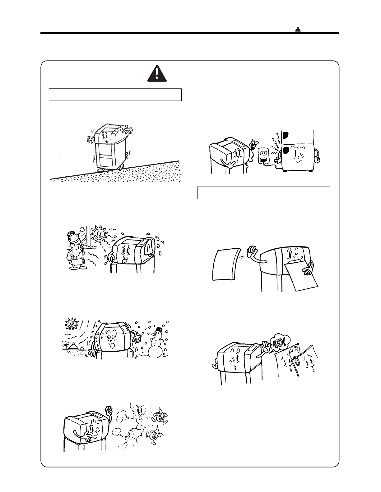
Installation location
General operation instructions
¡Install the machine in a level place.
¡Do not install the machine in a place subject
to direct sunlight or near heating equipment.
¡Do not install the machine in a place subject
to extreme temperatures (high or low), or in a
place subject to heavy vibration.
¡Avoid installing the machine in a place with
high humidity, or with large amount of oil,
iron filings, or dust.
¡Do not connect the cutter to a power outlet
that is also used for equipment that
generates noise, such as large-size office
equipment or refrigerators.
¡ Do not use the cutter to cut paper that
exceeds the specification paper thickness.
Doing so could result in breakdown.
¡ Do not attempt to cut paper with staples,
paper clips or any other pieces of metal
attached to it.
¡Use a dry cloth to remove paper cuttings
collected in the machine and to clean the
rubber rollers or other parts. Be sure to pull
the power supply plug out from its outlet
before cleaning.
Safety instructions
Page 6
- 5 -
q
Safety instructions
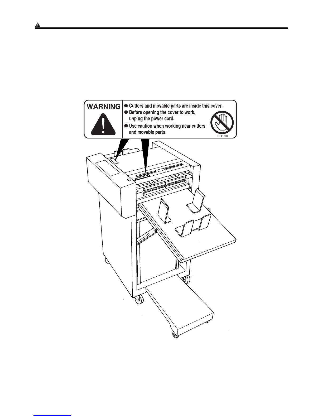
DLocations of warning stickers
The locations of the machine's warning stickers are shown below. To ensure safe work, read the stickers and
heed their instructions. Keep the stickers clean at all times. If they become damaged or peel off, replace them
with new ones.
Page 7

- 6 -
No. Part No. Name Q'ty
q
w
e
L8-T1080
L8-T1070
L8-T1100
Warning Sticker 1
Warning Sticker 2
Warning Sticker 3
2
1
1
w
e
Safety instructions
Page 8
- 7 -
1. Names and functions of each part
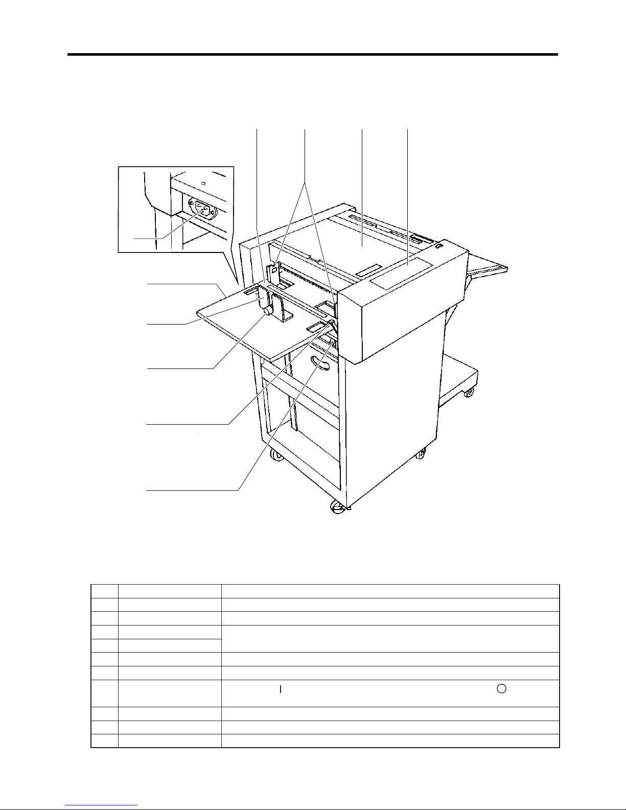
s
Feed side
No. Name Function
q
Front safety cover Open this cover to adjust the paper thickness or to remove jammed paper.
w
Operation panel See "Names and functions of the operation panel" on p. 9.
e
Paper tray
Load the paper into these trays.
r
Auxiliary paper tray
t
Paper stopper Guides the trailing edge of the paper.
y
Guide Hold the trailing edge of the paper.
u
Power switch
Press the [ ] side of the switch to turn the power on, and the [ ] side to
turn it off.
i
Inlet The power cord (an accessory) is inserted into this.
o
Paper guides Set the position of these guides to match the width of the paper.
!0
Lock lever Pull this lever backward (toward you) to lock the paper guides.
qoe w
i
r
t
y
!0
u
Page 9

- 8 -
1. Names and functions of each part
s
Ejection side
No. Name Function
!1
Rear safety cover Open this cover to adjust the margin slitters or to remove jammed paper.
!2
Ejection tray Receives ejected paper.
!3
Ejection stopper Stops the leading edge of ejected paper sheets.
!4
Ejection guides Laterally positions the ejected paper.
!5
Knob Moves the margin slitter. Turn clockwise to lock.
!6
Pointers Indicate the margin cutting position.
!7
Scale Measures the paper dimensions for cutting.
!8
Aligner Moves the left and right margin slitters simultaneously.
!9
Trash box Cut-off margins are deposited into this box.
!7
!2
!9
!4
!5
!6
!1
!8
!3
Page 10

- 9 -
2.
Names and function of the operation panel
No. Name Function
q
Liquid crystal Display
Displays various messages.
w
COVER indicator Lights when a safety cover is open.
e
JAM indicator Lights when a paper jam occurs.
r
PAPER indicator Lights when there is no paper in the paper tray.
t
READY TO RUN
indicator
In the RUN mode, lights to indicate the machine is ready to run.
y
POWER indicator Lights when the power is on.
No. Name Function
q
F button
Function button - used in conjunction with other buttons to execute functions
such as cutting dimension registration.
w
MODE button Switches among the LCD's display modes.
e
SET button
In the RUN mode, pressing this button executes test cutting.
In the SET mode, pressing this button memorizes cutting dimensions.
r
3
button
When the machine is stopped in the RUN mode, or due to a jam, pressing
the + button will move the paper forward, and pressing the - button will
move it backward.
t
4
button
y
RESET button
A multifunction button that when pressed at the same time the STOP button
is pressed,the number of sheets fed and cut will be reset.
If pressed for three or more seconds in the Freesize Input Mode, the current
registered data will be erased.
u
START button
In the RUN mode, pressing this button starts cutting operation (except when
a paper jam has stopped operation).
i
STOP button
Press this button to stop the machine. Also press this button to restart the
machine after it has been stopped by a paper jam (but note that you must
first eliminate the cause of the jam before the machine can be restarted).
Display unit
q w t yer
tewq
y u i
r
Operation unit
Page 11

- 10 -
3. Procedures for using the machine
Setting the ejection tray in place1
1.2.Lift the ejection tray upward.
Hook the slots in the tray's struts onto the pins on both
sides of the machine body. Make sure that the tray is
securely set in place.
Note
¡ The ejection tray can be adjusted to two different
inclination angles. Select the angle appropriate for the
paper's size and quality.
Connecting the power2
1.
Fit the female plug of the power cord (one of the
accessories) into the inlet on the feed side of the
machine.
1.
Move the auxiliary paper tray in the direction indicated by
the arrow.
2.
Insert the power cord's male plug into power outlet.
Setting the auxiliary paper tray3
Power cord
Female plug
Ejection tray
Strut
Pin
Inlet
Auxiliary
paper tray
Page 12

- 11 -
Loading the paper4
1.2.Lift up the paper tray's lock lever, to unlock the paper
guides.
Align the paper guides with the marks for the size of
paper to be loaded.
3.
Take a stack of paper, flip through it to loosen up the
sheets, and straighten up the edges of the stack on a
level surface.
4.
Slightly curl up both sides of the paper stack, and load it
into the paper tray, so that it rests between the guides.
3. Procedures for using the machine
¡Be sure to loosen up the paper sheets before loading
the stack into the tray. Otherwise, paper feed errors or
jams will occur.
IMPORTANT
¡The sides of the paper stack must be curled up
slightly when it is loaded into the tray, or it will not be
loaded properly.
IMPORTANT
5.
Position the paper guides so that they match the width of
the paper, then push down the lock lever to lock them in
place.
¡The amount of paper loaded must not exceed the line
on the maximum load sticker.
¡ Position the paper guides so that they are just
touching the paper, not pressing on it.
IMPORTANT
Lock lever
Lock lever
Paper guides
Paper guides
Paper size marks
Line
Page 13

- 12 -
3. Procedures for using the machine
6.
Fit the paper stopper to the paper tray, so that it rests
against the trailing edge of the paper.
7.
Fit the No. 1 paper retainer into the gap between the
stopper's prongs, so that it holds down the paper.
1.
Fit the No. 2 paper retainers (accessories) into the gap
between the paper guides' prongs.
S If the paper is laminated, or curls to a large degree:
• Be sure to use the No. 2 paper retainer accessories if
the paper curls to a large degree. Otherwise the paper
will not be fed properly.
IMPORTANT
Paper
stopper
No.1
Paper
retainer
No.2 Paper retainer
Adjust the paper thickness5
1.
Open the front safety cover.
Front safety cover
Page 14

- 13 -
3. Procedures for using the machine
3.
Check the separator plate's degree of emergence. To do
so, remove the thumb screw indicated, and open out the
suction unit. This will render the separator plate visible.
1.
Press and hold down the F button, and press the MODE
button. The display will change in the way shown at
right.
2.
Use the MODE button to select "Normal" or "Heavy".
(Pressing the MODE button toggles the asterisk "1"
between the two items. The asterisked item is the one
selected.) Select "Heavy" for thick paper.
3.
Press the SET button. The item selected in 2. will be set,
and the RUN mode display will reappear.
*You can tell whether "Normal" or "Heavy" has been set
by the presence/absence of a "1" in the Run mode
display. See figure at right.
2.
Turn the adjuster knob to adjust the separator plate's
position to match the paper thickness.
The separator plate's standard position is the fullyemerged position.
¥ For thin paper: Turn the adjuster knob in the "L"
direction to make the separator plate emerge.
¥ For thick paper: Turn the adjuster knob in the "H"
direction to make the separator plate retract.
¥ Adjust the separator plate's position to suit the paper
feed situation.
Thumb screw
Adjuster knob
Suction unit
Separator plate
IMPORTANT
¥ If a jam occurs in the paper feed unit during operation,
carry out the following procedure to eliminate the jam.
IMPORTANT
[Run]
No.01: 3:T 307.0
[PaperWeight ]
1
No rma l Heavy
[PaperWeight ]
No rma l
1
Heavy
[Run] [Run]
1
¡When "Normal" is set: ¡When "Heavy" is set:
Asterisk displayed
Page 15

- 14 -
3. Procedures for using the machine
Adjusting the margin slitter6
1.
Place 1 sheet of the paper to be used against the scale on
the safety cover, and align the center of the paper with
the scale's central line.
2.
Loosen the left and right margin slitter knobs, and align
the pointers with the required slitting positions.
3.
Tighten the margin slitter knobs.
1.
Open the rear safety cover.
2.
Loosen the fixing knob.
The alignment dial is now ready for use.
¥ The alignment dial can be used to align the left and right
margin slitters simultaneously, as follows.
Note
Scale
Paper
Slitter knobs
Rear safety cover
Fixing knobAlignment dial
Align
Page 16

- 15 -
4. Basic operation
About modes and mode displays
The DocuCutter has 4 modes. After completing the "Procedures for using the machine" (p.10), turn on
the power, select a registration number (in the Select mode), and perform test cutting. Then use the
RUN mode to run the machine.
* No cutting dimensions are registered when the machine is shipped. After turning the power on for
the first time, register cutting dimension data (in the Freesize Input mode) before running the
machine.
1
(Operation)
[Run mode] Mode for operation
aP.18
Testing
Press
Press
aP.18
Operation
MODE
qTest cutting (executed by pressing SET
button)
wOperation start (executed by pressing
START button)
¥ Operation stops when counter reaches
set quantity, or when STOP button is
pressed
¥ Use the RESET button to reset the
counter
¥ Use the button to move the paper
forward
¥ Use the button to move the paper
backward
2
(Selection)
[Select mode]
For selecting
registration number
aP.17
Selection
MODE
qSelection of registration No.
¥ No. Cut(side-margins-only cut)
¥ No. 00
¥ No. 98
(Use and buttons to select
number. Use F button to view registered
data.)
wConfirmation of selection
Press the SET button to confirm the
selection. "#", indicating "selected" will
be displayed.
[Run]
No.01: 3:T 307.0
[Select ] #
No.01: 3:T 307.0
Page 17

- 16 -
4. Basic operation
Press
As necessary
[Offset Adjust]
To [Run mode]
For temporarily offsetting
cutting position
aP.21
Offsetting
MODE
qSetting of offset dimension
¥ Top 1.0mm
¥ Top 0.5mm
¥ Standard 0mm
¥ Bottom 0.5mm
¥ Bottom 1.0mm
(Use and buttons to select value.)
Press
3
(
Registration
)
[Freesize mode]
For registering / deleting
cutting dimensions
aP.19
Registration
aP.21
Deletion
MODE
qSetting of registration number (No. 00 -
98)
(Use and buttons to select
number. Press SET button to confirm.)
wSetting of number of pieces (2-15
pieces)
(Use and buttons to select
number. Press SET button to confirm.)
eSetting of leading edge cutting
dimension
(Use and buttons to select value.
Press SET button to confirm.)
rSetting of middle cutting dimension
(not used with 2 pieces)
(Use and buttons to select value.
Press SET button to confirm.)
tSetting of trailing edge cutting
dimension
(Use and buttons to select value.
Press SET button to confirm.)
¥ To delete registered data:
(Use and buttons to select
registration number, and press RESET
button for at least 3 seconds to delete.)
[Freesize Input]
No . ?
44
> No.00
[Of fset Adjust ]
0mm
Page 18

- 17 -
4. Basic operation
Turning on the power1
Selecting the cutting dimensions2
1.
Press the [ ] side of the power switch, to turn the power
on. When the power is turned on, the screen that was
displayed when the power was last turned off appears on
the LCD panel.
1.
Press the MODE button as many times as needed to
select the SELECT mode.
2.
Use the "+" and "-" buttons to select a pre-registered
number.
Pre-register cutting dimensions, and call them up as
required by selecting registration numbers.
Numbers 0 through 98 are available for registering
cutting dimensions.
* To turn off the power:
Press the [ ] side of the power switch.
Note
¥ No dimensions are registered when the machine is
shipped. For the registration procedure, see "Registering
the cutting dimensions" below.
Note
¥ To view the registered data:
Press and hold down the F button. The registered cutting
data will be displayed sequentially.
DocuCu t t er 535
Ver .
41.11
[Run]
No.01: 3:T 307.0
[Run]
No.01: 3:T 307.0
[Select ]
No.01: 3:T 307.0
[Select ]
No.01: 3:T 307.0
[Select ]
No.01: 1: 10.0mm
Power switch
ON
OFF
Registration No.
Sequential display
Number
of pieces
Total
Length
¡Screen displayed when power was last turned off
Page 19

- 18 -
4. Basic operation
Performing test operation to check the cutting dimensions
3
3.
Press the SET button. "#" will be displayed, and then the
RUN mode display will appear. The machine is now ready
to run using the cutting dimensions registered under the
number selected in 2. above.
1.
Press the SET button.
A single sheet of paper will be test-cut. Check that it is
cut correctly.
a
Press the START button. Operation will start.
Press the STOP button.
* To stop operation:
See the instructions in "Using the offset adjust mode"
below.
* To temporarily offset the cutting position:
* When the trash box becomes full:
Press the STOP button.
Pull out the trash box, and empty the accumulated paper
scraps from it.
Push the emptied trash box back into the machine, then
press the START button. Operation will restart.
2.
Position the ejection stopper and ejection guides so that
they are 3mm away from the edges of the cut paper.
Starting operation4
¥ Paper jams will occur if the trash box fills up
completely. Empty the trash box before it fills up
completely.
¥ When cutting long paper, do not use the trash box, or
paper jams will result.
IMPORTANT
[Run]
No.01: 3:T 307.0
[Select ] #
No.01: 3:T 307.0
Ejection guides
Ejection stopper
Trash box
Page 20

- 19 -
5. Registering cutting dimensions
Overview
Pre-register cutting dimensions, and call them up as
required by selecting registration numbers.
Numbers 0 through 98 are available for registering
cutting dimensions.
¥ Do not register the following dimensions. They will
result in paper jams in the machine's interior.
¥ Leading edge cut (CUT No.1) 3.2mm or less.
¥ Middle cut (CUT No.2) 90mm or less.
¥ Trailing edge cut (CUT No.3) 3.2mm or less.
IMPORTANT
Procedure for registering cutting dimensions2
1
1. Press the MODE button as many times as needed to
select "Freesize Input".
6.
Use the "3" and "4" keys to select the leading edge cut
(CUT No. 1) dimension.
7. Press the SET button. The leading edge cut (CUT No. 1)
dimension selected will be set.
4.
Use the "3" and "4" keys to select the number of
pieces.
5. Press the SET button. The number selected will be set. (2
through 15 can be set for the number of pieces.)
2.
Use the "3" and "4" keys to set a registration number.
3. Press the SET button. The registration number will be
set.
[Freesize Input]
No . ?
44
>No.00
[Freesize Input]
No . ?
44
>No.01
Pieces ? : 3
Length? T: 5.0
1: 5.0mm
Example : selecting No.1
¡Brackets( )indicate the case with 3 pieces
Leading edge cut
(CUT No.1)dimension
Middle cut
(CUT No.2)dimension
Trailing edge cut
(CUT No.3)dimension
Example : selecting 3 pieces
Example : inputting 5mm
for CUT No.1
Total length
CUT No. Cutting length
Page 21

- 20 -
5. Registering cutting dimensions
11.
a
a
Press the SET button. The trailing edge cut (CUT No. 3)
dimension selected will be set. Registration is now
complete.
The display in step 1 will reappear on the screen.
To register more dimensions, repeat the above
procedure.
To run the machine at this point:
¥ If you set only the leading edge cut (CUT No. 1)
dimension, to a value in the range 101.5-170mm, or
only the trailing edge cut (CUT No. 3) dimension, to a
value over 210mm:
The number of cuts will be automatically increased,
for smoother processing of the cut paper. Note also
that the set number of cuts will also increase, and the
number-of-sheets-cut-count will be decreased.
IMPORTANT
8.
Use the "3" and "4" keys to select the middle cut (CUT
No. 2) dimension.
9. Press the SET button. The middle cut (CUT No. 2)
dimension selected will be set.
10.
Use the "3" and "4" keys to select the trailing edge cut
(CUT No. 3) dimension.
Length? T: 105.0
2:100.0mm
Length? T: 110.0
3: 5.0mm
Press the MODE button as many times as needed to
select the SELECT mode. Then refer to "Selecting the
cutting dimensions" on p.17.
Example : inputting 100mm for CUT No.2
Example : inputting 5mm for CUT No.3
Page 22

- 21 -
6. Other functions
Deleting registered data
To temporarily offset the cutting position
1.
Press the MODE button as many times as needed to
select "Freesize Input".
1.
Press the MODE button as many times as needed to
select "Offset Adjust".
2.
Use the "3" and "4" keys to set the offset dimension.
3.
Press the MODE button as many times as needed to
select the RUN mode.
4.
Press the START button, to start operation. Cutting will
be executed with the offset that was set.
The offset adjust mode is used to temporarily offset the
cutting position. The offset can be set to 20mm, with
pitch 0.5mm.
3
4
2.
Use the "3" and "4" keys to select a pre-registered
registration number.
3.
Press the RESET button and hold it down for at least 3
seconds. The buzzer will sound, and the data registered
under the specified number will be deleted.
¥ When the CUT No. is changed, the offset dimension is
reset to 0mm.
IMPORTANT
[Freesize Input]
No . ?
44
>No.00
[Freesize Input]
No . ?
44
>No.02
[Offset Adjust]
0mm
[Offset Adjust]
Top 0.5mm
[Run]
No.01: 3:T 307.0
Example : selecting No.2
Example : selecting Top 0.5mm
¡Example : setting 5mm offset
With Bottom
5.0mm
With 0mm
(standard)
With Top
5.0mm
Page 23

- 22 -
7. Suggestions
Messages displayed on LCD when a jam occurs
When a paper jam occurs, the buzzer sounds and a message is displayed on the LCD panel. When this
happens, take the corrective action given below.
Message Cause and corrective action Page
Shut Cover !! Cause: Safety cover (front or rear) is open.
Corrective action: Close the cover.
4
Paper Jam !!
Feed jam 1
Cause: Paper feed error.
Corrective action: Adjust the paper separator.
13
Paper Jam !!
Center jam 2
Cause: Paper jammed just before the cutter.
Corrective action: • Check that cutting dimensions are appropriate.
• Remove the jammed paper and press the STOP button.
23
Paper Jam !!
Center jam 3
Cause: Paper jammed just before the cutter.
Corrective action: • Check that cutting dimensions are appropriate.
• Remove the jammed paper and press the STOP button.
23
Paper Jam !!
Cutter jam 4
Cause: Paper jammed inside the cutter.
Corrective action: • Check that cutting dimensions are appropriate.
• Remove the jammed paper and press the STOP button.
24
Cutter Lock !!
jam 5
Cause: Cutter does not cut properly.
Corrective action: • Check if the paper being cut is outside the specification
range.
• Remove the paper causing the problem and press the
• STOP button.
24
Paper Jam !!
Slitter jam 6
Cause: Paper jammed inside the slitter.
Corrective action: Remove the jammed paper and press the STOP button.
24
Elevator Error Cause: Feed elevator error.
Corrective action: Press the STOP button. If the elevator doesn't return to
normal, call the service representative.
4
Elevator Full
Error
Cause: Too much paper in the paper tray.
Corrective action: Reduce the amount of paper to below the line on the
maximum load sticker.
11
Page 24

- 23 -
7. Suggestions
Corrective action for paper jams
Removing jammed paper from the feed unit
1.
Turn off the power switch, and pull the power cord plug
out from the outlet.
¥ If you will have to put your hands near moving parts to
remove the jammed paper, first remove the power cord
plug from the outlet.
2.
Open the front safety cover.
3.
Remove the fixing thumb screw from the suction unit.
4.
Raise up the suction unit, and remove the jammed paper.
WARNING
¥ After removing the paper, don't forget to lock the
suction unit by screwing its fixing thumb nut back in
place.
IMPORTANT
Power switch
Front safety cover
Thumb screw
Jammed paper
Suction unit
OFF
Page 25

- 24 -
7. Suggestions
Removing jammed paper from the cutter or ejection unit
¥ If you will have to put your hands near moving parts to
remove the jammed paper, first remove the power cord
plug from the outlet.
¥ The cutter unit and slitter unit contain hazardous
cutting edges inside them. Keep your hands away from
these units' interiors.
¥ To remove jammed paper, use the tweezers included in
the accessories, or a similar tool.
WARNING
1.
It is sometimes possible to remove the paper by pressing
the "3" key to move it forward, and the "4" key to move
it backward.
* Using these keys may however make the paper jam
worse. Watch the condition of the jammed paper as you
operate the keys.
1.
Turn off the power switch, and pull the power cord plug
out from the outlet.
2.
Open the rear safety cover. If the paper is jammed in the
cutter unit, open the front safety cover.
3.
Remove the jammed paper.
4.
If the paper is jammed in the cutter unit, use the tweezers
included in the accessories to remove it.
Using the "3" and "4" keys to remove jammed paper.
1
If the jammed paper cannot be removed by the procedure described in "1"
2
Front safety cover
Rear safety cover
Page 26

- 25 -
8. Specifications and accessories
Model name DC-535 Cutter
Paper size
Minimum: 6" (width) 56" (length)
Maximum: 12.6" (width) 518" (length)
Cut paper size
Minimum: 6" (width) 54" (length) (postcard size)
Maximum: 11" (width) 517" (length)
Paper thickness
61-249g/m3(but depending on paper quality and lamination condition, certain
paper within this thickness range may not be cuttable)
Paper holding capacity 25" (0.8mm
)
Leading edge cut
dimension
Minimum: 0.125 (3.2mm)
Maximum: 0.63" (16mm)
Trailing edge cut
dimension
Minimum: 0.125" (3.2mm)
Maximum: 0.63" (16mm)
Side cut
Minimum: 0.125" (3.2mm)
Maximum: 5" (127mm)
Cutting precision 0.5mm (with paper cutting length not exceeding 17")
Cutting speed
35 sheets / minute (when cutting leading and trailing edges of 8.5" 511" paper)
55 sheets / minute (when cutting both sides of 8.5" 511" paper)
Feed method Air suction method
Stacker Drop type
Power supply
AC 120V Type
AC 120
V 10%
, 50/60Hz, 1.2A
Machine dimensions
(mm)
When out of use: 503 (W) 578 (D) 51040 (H)
When in use: 1160 (W) 5578 (D) 5954 (H)
Machine weight (kg) 64
AC 230V Type
AC 230V 10%, 50/60Hz, 0.6A
3
4
3
4
3
4
Name Q'ty Name Q'ty
Power cord 1 Trash box 1
Instruction Manual 1 Paper stopper 1
Tweezers 1 No. 1 paper retainer 1
Ejection stopper 1 No. 2 paper retainers 2
Ejection guides 2
Note : The specifications and other data above are subject to change without notice.
s
Specification
s
Accessories
Page 27

L8-Y1030 1998. 12
Printed in Japan
DUPLO SEIKO CORPORATION
353 KOUDAI KOKAWA-CHO NAGA-GUN
WAKAYAMA-KEN JAPAN
 Loading...