

Page 1

INSTRUCTION MANUAL
STITCHER FOLDER
DBM-600
TRIMMER
DBM-600T
Original instructions
Be sure to read this manual prior to use.
Please leave this manual at the site of use for easy reference.
Page 2

Introduction
Thank you for purchasing a Duplo product.
Be sure to read this manual and "Safety Guide A" supplied with this product before use. “Safety Guide”
contains information for correct and safe use of this product.
After reading, leave the manual and “Safety Guide” at the site of use for easy reference whenever questions
related to the product arise in the future.
Symbols
In this manual, several symbols are used to indicate important warnings. Please make sure to read
instructions accompanied by these symbols. These symbols have the following meanings.
Describes instructions which must be followed in use.
Be sure to read the instructions to avoid problems due to incorrect operations.
Indicates supplementary or useful information.
Describes names of related items and supplementary instructions.
Trademark
The product name and company name used in this manual are trademarks or registered trademarks of the
respective companies.
Statement of Photobiological Safety
This product not only employs LED lamps as an indicator but also as lighting.
The LED light is conrmed with a safety standard IEC62471 and classied into the risk group 1 (low risk). The
risk group 1 (low risk) LED light does not lead to injury required such as an access restriction. However the
risk depends upon a distance between eyes and the LED lamp.
Please see a part “Name and Function” in this instruction manual that points to a place for LED lamp in the
product.
Do not stare into the LED lamp. Do not come closer to the LED lamp intentionally. A decrease in distance
between eyes and the LED light causes an increase in the risk.
For North America
Note:
In a residential area this product may cause radio interference in which case the user may be required to take
adequate measures.
This equipment has been tested and found to comply with the limits for a Class A digital device, pursuant
to Part 15 of the FCC Rules. These limits are designed to provide reasonable protection against harmful
interference when the equipment is operated in a commercial environment. This equipment generates, uses,
and can radiate radio frequency energy and, if not installed and used in accordance with the instruction
manual, may cause harmful interference to radio communications. Operation of this equipment in a
residential area is likely to cause harmful interference in which case the user will be required to correct the
interference at his own expense.
Page 3

Safety Precautions
Safety Precautions
Power supply
• Make sure the power supply used is always within the following range.
Power supply : 120 V AC, 60 Hz (North America)
220 to 240 V, 50/60 Hz (EU)
• When you power other appliances from the same AC outlet, make sure that the combined power
consumption does not exceed the power supply capacity.
Rated power: DBM-600
430 W (North America)
465 W (EU)
DBM-600T
625 W (North America)
645 W (EU)
Rated current: DBM-600
4.5 A (North America)
2.5 A (EU)
DBM-600T
6.5 A (North America)
3.4 A (EU)
Operating environment
Operate this unit in the following environment.
• where the temperature range is between 5 and 35°C/41 and 95°F (–10 to 50°C/14 to 122°F in storage)
• where the humidity range is between 20 and 85% RH (10 to 90% RH in storage, however no condensation)
• which is not subject to direct sunlight
• which is subject to little or no vibration
• which is free from air-borne salt
• where there are no harmful chemicals
• where the unit is not exposed to water
i
Page 4

Safety Precautions
WARNING/CAUTION labels
"WARNING" and "CAUTION" labels are pasted on the machine to ensure user safety.
Do not remove or change them.
When the labels become dirty or are lost, be sure to contact your dealer for a new one.
For EU
ii
Page 5

For North America
Safety Precautions
iii
Page 6

Safety Precautions
Safety devices
[3]
[2]
[4]
[1]
[1]
No. Name Function
[1] Emergency stop switch Press this switch to stop the machine in emergencies. Turn the pressed
switch to the right to release it. While pressed, the machine will not
start and its moving parts will also not move.
[2] Top cover interlock switch L The switch is associated with the cover and it activates the interlocking
[3] Top cover interlock switch R
[4] Top cover interlock switch
system which consists of the protective guards, the electrical circuit
and the actuators.
The hinged or sliding cover, which can be manually opened or closed,
works as an interlocking guard associated with the electrical drive
circuit so that the hazardous moving parts do not move while the
cover is opened.
iv
Page 7

[1]
Safety Precautions
[3]
[2]
[5]
[6] [8]
No. Name Function
[1]
Fixed cover The cover is xed by screws to prevent hazardous parts from being
to
[8]
exposed. Do not remove the cover. Doing so could cause serious
injury.
[4]
[7]
v
Page 8

Safety Precautions
Memo
vi
Page 9

Contents
Contents
Safety Precautions .............................................i
Power supply .................................................................................i
Operating environment ............................................................i
WARNING/CAUTION labels .....................................................ii
Safety devices .............................................................................iv
Chapter 1 Before Operation
1. Features ...................................................1-1
1-1. Features of the DBM-600 ......................................1-1
1-2. Features of the DBM-600T ...................................1-2
2. Names and Functions of
Components ............................................ 1-3
2-1. DBM-600 external parts ........................................1-3
2-2. DBM-600T external parts .....................................1-5
2-3. DBM-600 internal parts (stitching section) ... 1-6
2-4. DBM-600 internal parts (folding section) ......1-8
2-5. DBM-600T internal parts ....................................1-10
2-6. Stitcher head ...........................................................1-12
3. Accessories ............................................1-13
3-1. Accessories for the DBM-600 ............................1-13
3-2. Accessories for the DBM-600T .........................1-14
4. DBM-600 Control Panel .......................1-15
4-1. Names of control panel .......................................1-15
4-2. Screen descriptions ..............................................1-16
4-3. Colors of the keys on the setting screen ......1-16
4-4. [Main] screen ...........................................................1-17
4-5. [Adjust] screen ........................................................1-25
4-6. [Function] screen ...................................................1-26
4-7. [Options] screen .....................................................1-31
5. DBM-600T Control Panel .....................1-36
5-1. Names of control panel .......................................1-36
5-2. Screen menus .........................................................1-37
6. Stitching Width .....................................1-38
7. Options ..................................................1-40
7-1. DBM-SSW ..................................................................1-40
7-2. DBM-LSW ..................................................................1-41
7-3. DKT-K ..........................................................................1-41
8. Workflow ...............................................1-42
Chapter 2 Basic Operation
1. Turning On/Off the Power ..................... 2-1
1-1. Turning on the power ............................................2-1
1-2. Turning o the power ............................................2-2
2. Setting the Control Panel ......................2-3
2-1. Setting the standard size ......................................2-4
2-2. Setting the custom size .........................................2-7
3. Preparing the DBM-600 for
Operation ..............................................2-16
3-1. Using the paper guide .........................................2-16
3-2. Attaching the parts for page insertion .........2-16
3-3. Moving the stitch release levers (for corner
stitching) ...................................................................2-17
3-4. Adjusting the paper receiver stopper
(for side stitching, corner stitching) ...............2-17
3-5. Aligning the paper passage lines ....................2-18
4. Preparing the DBM-600T for
Operation ..............................................2-19
5. Making the Upstream Unit Ready ......2-20
6. Adjusting Each Section
(Step Mode) ...........................................2-20
6-1. Starting the step mode .......................................2-20
6-2. Adjusting the stitching section (when
“stitching on” has been selected) ....................2-21
6-3. Adjusting the folding section (when “folding
on” has been selected).........................................2-23
6-4. Adjusting the trimming section (when
“trimming on” has been selected) ..................2-25
7. Checking Finished Booklets ................2-25
7-1. When paper does not align ...............................2-25
7-2. When stitching and folding positions do not
align ............................................................................2-27
7-3. Adjusting stitching and folding positions
simultaneously .......................................................2-29
7-4. Adjusting the stitching width ...........................2-30
7-5. When fold is skewed ............................................2-31
7-6. When the stitching position is not at right
angle to paper ........................................................2-32
7-7. When paper does not align on the belt
stacker ........................................................................2-33
7-8. When there is a scratch on a booklet ...........2-34
7-9. Stripping occurs on the surface of a
booklet .......................................................................2-36
8. Adjusting Each Part (DBM-600) ..........2-37
8-1. Adjusting the infeed paper holder .................2-37
8-2. Adjusting the stitching paper holder ............2-37
8-3. Adjusting the height of the stitch ejection
roller R ........................................................................2-38
8-4. Adjusting the folding roller gap ......................2-38
8-5. Adjusting the height of the insertion
roller ............................................................................2-39
8-6. Adjusting the pressure adjustment lever ....2-39
8-7. Using the fold paper holder ..............................2-40
8-8. Adjusting the ejection pressure ......................2-40
8-9. Using the paper receiving guides F and B ...2-41
vii
Page 10

Contents
8-10. Using the paper guide bracket ........................2-41
8-11. Adjusting the height of the paper receiver
full loading sensor .................................................2-42
8-12. Removing booklets from the paper
receiver ......................................................................2-42
9. Adjusting Each Part (DBM-600T) ........2-42
9-1. Adjusting the infeed rollers ...............................2-42
9-2. Adjusting the stopper angle .............................2-43
9-3. Adjusting nished length ..................................2-43
9-4. Adjusting the press angle unit .........................2-44
9-5. Adjusting the infeed sensor height ...............2-45
9-6. Preparing for the loop stitching ......................2-45
10. Adjusting the Paper Guide Roller
Unit ........................................................2-46
10-1. Adjusting the position of the paper guide
roller unit ...................................................................2-46
10-2. Replacing with the paper guide roller unit
(small) .........................................................................2-47
11. Setting the Conveyance Belt
Timing ....................................................2-47
11-1. Adjusting conveyance stop timing ................2-47
11-2. Adjusting conveyance restart timing ............2-47
11-3. Adjusting start timing and operating time of
the stacker belt .......................................................2-47
12. Starting Binding Operations ...............2-48
Chapter 3 Advanced Operation
1. Sending Paper Manually ....................... 3-1
1-1. Using the DBM-600 HAND FEED KIT
(optional) ....................................................................3-1
1-2. Using the DSF-2200 HAND FEED KIT
(optional) ....................................................................3-1
2. Using the DBM-600 AIR KIT (Option) .... 3-2
3. 2-stitch Binding with 4 STITCH KIT
(option) Attached ................................... 3-2
1-3. Cleaning the sensor ................................................4-2
2. Emptying the Scrap Box ........................ 4-3
3. Stitcher Head ..........................................4-4
3-1. Information on wire we specify .........................4-4
3-2. Removing wire ..........................................................4-4
3-3. Wire threading ..........................................................4-5
3-4. Installing new wire ..................................................4-7
3-5. Lubricating the stitcher head .............................4-8
Chapter 5 Trouble Guide
1. DBM-600 Error Code ..............................5-1
1-1. Error related to emergency stop switch and
covers ...........................................................................5-1
1-2. Paper jam error .........................................................5-2
1-3. Downstream unit and motor error ...................5-2
1-4. Other errors ................................................................5-2
1-5. Errors requiring a service call ..............................5-3
2. DBM-600T Error Code ............................ 5-3
2-1. Error related to emergency stop switch,
covers, etc. ..................................................................5-3
2-2. Paper jam error .........................................................5-4
2-3. Downstream unit and motor error ...................5-4
2-4. Errors requiring a service call ..............................5-5
3. Paper Jam ................................................ 5-6
3-1. Paper jam in the DBM-600 ...................................5-6
3-2. Paper jam in the DBM-600T ................................5-8
3-3. Step ejection............................................................5-10
4. Troubleshooting ...................................5-10
4-1. Entire machine ........................................................5-10
4-2. DBM-600 stitching section ................................5-10
4-3. DBM-600 folding section ....................................5-12
4-4. DBM-600 paper receiver and the stacker ....5-14
4-5. DBM-600T trimming section ............................5-14
4-6. Problem with nished booklets ......................5-15
4. Using the CALENDAR KIT (Option) ....... 3-3
5. Using the DKT-K (Option)....................... 3-3
5-1. Attaching the kicker support wheel unit .......3-3
5-2. Adjusting the position of the kicker ................3-4
5-3. Attaching the stopper ...........................................3-4
5-4. Using the sorting function ...................................3-5
6. Adjusting the Stitcher Head .................. 3-5
Chapter 4 Cleaning the Unit
1. Cleaning Each Part .................................4-1
1-1. Cleaning the conveyance belt and rollers .....4-1
1-2. Cleaning the LCD .....................................................4-1
viii
Chapter 6 Appendix
1. Specifications ..........................................6-1
2. Limit on Stitching Width ........................ 6-7
Page 11

Chapter 1 Before Operation
Chapter 1 Before Operation
1. Features
1-1. Features of the DBM-600
• The DBM-600 is a stitcher folder that can make a booklet in the following binding methods.
[A] Saddle stitch
[B] Saddle stitch and fold
[C] Fold
[D] No stitch and no fold
[E] Side stitch
[F] Side stitch and fold
[G] Corner stitch
[H] Page insertion(*)
(*) Page insertion is a 6 to 22-page booklet consisting of a sheet of A3 (LGR) with a sheet of A4 (LTR).
[B][A] [C] [D]
[F] [G][E] [H]
1-1
Page 12

Chapter 1 Before Operation
• The DBM-600T (trimmer) can be connected to the DBM-600 as a downstream unit.
DBM-600
DBM-600T
• The DBM-600 can be used as a system by connecting it to other machines such as a collator.
• When the 4 STITCH KIT (option) is installed, four stitches can be applied to a booklet.
[A] Saddle stitch
[B] Saddle stitch and fold
[C] Side stitch
[D] Side stitch and fold
[B][A] [C] [D]
• When the CALENDAR KIT (option) is installed, a calendar as shown in the gure below can be made.
1-2. Features of the DBM-600T
• The DBM-600T is a fore-edge trimmer and is used as a downstream unit of the DBM-600.
The trimming width is 1 to 25 mm/0.04 to 0.98 inch. When the number of sheets is 12 or less, up to 75
mm/2.95 inches can be trimmed.
• A head and foot trimmer can be connected to the DBM-600T as a downstream unit.
1-2
Page 13

Chapter 1 Before Operation
2. Names and Functions of Components
2-1. DBM-600 external parts
[3]
[4]
[1]
[2]
[5]
[6]
parsparssparts
[7]
[8]
[15]
[14]
[9] [10] [11] [12] [13]
No. Name Function
[1] Power switch
[2] Inlet for D Link connector Insert the D Link cable of the machine equipped with a D Link unit into
[3] Top cover R Cover for ensuring user safety. This machine will not operate if open.
”1-2. Turning off the power” (p.2-2)
this connector.
1-3
Page 14

Chapter 1 Before Operation
No. Name Function
[4] Control panel Use this to operate the machine.
(p.1-15)
[5] Emergency stop switch Press this switch to stop the machine in emergencies. Turn the pressed
switch to the right to release it. While pressed, the machine will not
start and its moving parts will also not move.
[6] Top cover L Cover for ensuring user safety. This machine will not operate if open.
[7] Fold misalignment adjustment Adjusts the angle of the folding side guides.
[8] Fold misalignment adjustment knob
Secures the angle of the folding side guides.
(p.2-31)
(p.2-31)
screw
[9] Paper receiver knob screw Secures the position of the paper receiver.
(p.2-17)
[10] Paper receiver stopper Stops side-stitched or corner-stitched booklets on the paper receiver.
(p.2-17)
[11] Paper receiver Receives side-stitched or corner-stitched booklets.
(p.2-17)
[12] Paper receiver booklet holder Holds down the booklets ejected to the paper receiver.
[13] Handle Used to pull the paper receiver.
[14] Paper receiver full loading sensor
Secures the height of the paper receiver full loading sensor.
height adjustment
[15] Power inlet Connector for the power cord.
1-4
Page 15

2-2. DBM-600T external parts
[6]
Chapter 1 Before Operation
[7]
[4]
[5]
[1]
[2]
[3]
[8] [9]
No. Name Function
[1] Top cover Cover for ensuring user safety. This machine will not operate if open.
[2] Control panel Use this to operate the machine.
[3] Emergency stop switch Press this switch to stop the machine in emergencies. Turn the pressed
switch to the right to release it. While pressed, the machine will not
start and its moving parts will also not move.
[4] Paper guide roller unit Holds a booklet and supports the stacker.
[5] Damage prevention switch Prevents the paper guide roller unit from hitting the main unit.
[6] Kicker connector Connector for the kicker.
[7] Power inlet Connector for the power cord.
[8] Scrap box Ocuts are ejected to this box.
[9] Scrap box stopper Secures the position of the scrap box. When storing the scrap box,
push the box until it stops.
(p.1-36)
(p.2-46)
(p.2-46)
(p.4-3)
(p.4-3)
1-5
Page 16

Chapter 1 Before Operation
2-3. DBM-600 internal parts (stitching section)
[4]
[15]
[3]
[3]
[4]
[2]
[1]
[5]
[14]
[13]
[9]
[1]
[10]
[5]
[6]
[7]
[8]
[9]
[10]
[11]
[12] [12]
No. Name Function
[1] Stitcher head Stitches paper with a wire.
(p.1-12) (p.4-4)
[2] Stitch release lever Used to release stitching operations of the stitcher head. Use this for
corner stitches.
(p.2-17)
[3] CALENDAR KIT stopper Used for CALENDAR KIT (option). When paper reaches here, the
stopper goes down.
[4] Stitching side guide knob screw Used to secure the angle of the stitching side guides.
[5] Stitching side guide adjustment Used to adjust the angle of the stitching side guides.
[6] Stitch ejection roller R height
Adjusts the height of the ejection roller R.
(p.2-38)
(p.2-32)
(p.2-32)
adjustment
[7] Stitch ejection roller R knob screw Secures the ejection roller height.
[8] Stitch ejection roller R Conveys stitched paper to the folding section.
[9] Stitching paper holder knob screw Secures the stitching paper holder.
[10] Stitching side guide Aligns the sides of paper conveyed to the stitching section.
Infeed conveyance unit Conveys paper to the stitching section.
[11]
Stitching back guide Aligns the leading and trailing edges of paper conveyed to the
[12]
stitching section.
Infeed paper holder Prevents paper conveyed to the stitching section from rising.
[13]
Infeed conveyance unit lock lever Locks and releases the infeed conveyance unit.
[14]
Side-stitching stopper Used during side-stitching operations. Stops paper conveyed from the
[15]
(p.2-21)(p.2-27)
(p.2-38)
(p.1-27)(p.2-38)
(p.2-37)
(p.2-14)(p.2-25) (p.2-27)
(p.2-35)
(p.2-37)
(p.2-35)(p.5-6)
infeed section.
1-6
Page 17

Chapter 1 Before Operation
[4]
[3]
[2]
[1]
[6][5]
[7]
No. Name Function
[1] Saddle-stitching stopper lock plate Secures the saddle-stitching stopper angle.
[2] Saddle-stitching stopper angle
Adjusts the angle of the saddle-stitching stopper.
(p.2-32)
(p.2-32)
adjustment
[3] Saddle-stitching stopper Used during saddle stitching operations. Stops paper conveyed from
the infeed section.
[4] Stitch ejection roller L Conveys stitched paper to the folding section.
[5] Stitching paper holder Prevents paper conveyed to the stitching section from rising.
[6] Stitching paper holder knob screw Secures the stitching paper holder.
(p.2-32)
(p.1-27)
(p.2-37)
(p.2-37)
[7] LED inner lamp LED lamp for partially lighting up inside the machine.
1-7
Page 18

Chapter 1 Before Operation
2-4. DBM-600 internal parts (folding section)
[12]
[18]
[19]
[11]
[10]
[14][15]
[13]
[4]
[2]
[1]
[2]
[3]
[17]
[16]
[10]
[13]
[5]
[6] [7] [8]
[9][9] [11]
[14]
[15]
[12]
1-8
Page 19

Chapter 1 Before Operation
No. Name Function
[1] Folding back guide unit Unit for aligning the leading and trailing edges of paper conveyed to
the folding section.
(p.5-7)
[2] Folding back guide Aligns the leading and trailing edges of paper conveyed to the folding
section.
[3] Folding side guide Aligns the sides of the paper conveyed to the folding section.
(p.2-23) (p.2-25)
(p.2-14)(p.2-23)
[4] Press roller Presses paper folded into two.
[5] Folding roller Folds paper into two.
[6] Fold paper holder Prevents paper conveyed to the folding section from rising.
[7] Folding stopper Stops booklets conveyed to the folding section.
[8] Fold paper holder height adjustment Adjusts the height of the fold paper holder.
(p.2-38)
(p.2-40)
(p.2-16)
(p.2-40)
[9] LED inner lamp LED lamp for partially lighting up inside the machine.
[10] Press roller gap adjustment lever Adjust the clearance (gap) between the press rollers. Use this when the
surface of a booklet is stripped.
Pressure adjustment lever Adjusts the pressure of the press roller.
[11]
Ejection pressure adjustment lever Adjusts the ejection pressure.
[12]
Press roller gap xing lever Secure the clearance (gap) between the press rollers.
[13]
Fold ejection roller gap knob screw Secures the fold ejection roller gap adjustment lever.
[14]
Fold ejection roller gap adjustment
[15]
lever
Fold paper holder knob screw Secures the height of the fold paper holder.
[16]
Ejection at belt Ejects paper folded into two.
[17]
Page insertion roller height
[18]
Adjust the clearance (gap) between the fold ejection rollers. Use this
when the surface of a booklet is stripped.
Adjusts the height of the insertion rollers.
(p.2-36)
(p.2-39)
(p.2-40)
(p.2-36)
(p.2-36)
(p.2-36)
(p.2-40)
(p.2-16)(p.2-39)
adjustment
Page insertion roller knob screw Secures the height of the insertion rollers.
[19]
(p.2-16)
1-9
Page 20

Chapter 1 Before Operation
2-5. DBM-600T internal parts
[10]
[12]
[9][8]
[11]
[7]
[6]
[5]
[16]
[1]
[4] [3]
[2]
[13]
[12]
[14]
[15]
1-10
[15]
[16]
Page 21

Chapter 1 Before Operation
No. Name Function
[1] Stopper angle xing knob Loosen when adjusting the stopper angle adjustment.
[2] Stopper angle adjustment Adjusts the angle of the stopper.
(p.2-43)
(p.2-43)
[3] Conveyance belt Conveys a booklet. The height is automatically adjusted according
to the number of sheets in the booklet.
[4] Press angle unit Weakens pressure of the press bar against a booklet. Use this when
a booklet is torn by a stitch.
(p.2-44)
[5] Press bar Holds a booklet when trimming a booklet.
[6] Stopper Stops a booklet at the trimming position.
[7] Infeed sensor height adjustment knob
Adjusts the height of the infeed sensor.
(p.2-25)
(p.2-45)
screw
[8] Ocut ejection air Ejects ocuts, which are left after booklets are trimmed, into the
scrap box.
[9] Duct unit Sends ocuts ejection air to the knife section. Remove the duct
unit when paper jams under the infeed roller unit.
[10] Knife section Trims the fore-edge of a booklet.
(p.5-8)
[11] Infeed roller unit Sends booklets conveyed from the upstream unit to the inside the
machine.
(p.5-9)
[12] Support roller knob screw Used to change the position of the support rollers. When the
infeed roller unit has been raised using the infeed roller unit knob
screw, short booklets may stop under the infeed roller unit. In that
case, move the support roller knob screw downward to lower the
support rollers.
(p.2-19)
[13] Infeed roller adjustment Adjusts holding pressure of the infeed roller unit against a booklet.
(p.2-42)
[14] Infeed roller unit knob screw Used to raise the infeed roller unit. When the trimming width is
25 mm/0.98 inch or more, raise the infeed roller unit so that the
support rollers do not touch a booklet.
(p.2-19)
[15] Infeed roller Sends a booklet conveyed from the upstream unit to the inside of
the machine.
[16] Ejection roller Ejects a booklet to the downstream unit.
1-11
Page 22

Chapter 1 Before Operation
2-6. Stitcher head
[2]
[19]
[18]
[3]
[4]
[5]
[6]
[7]
[8]
[9]
[10]
[17]
[11]
[15]
[13]
[8]
[9]
[10]
[11]
[12]
[2]
[1]
[3]
[4]
[5]
[6]
[7]
[15]
[16]
[14]
”3. Stitcher Head” (p.4-4)
No. Name Function
[1] Wire guide spring Feeds wire to the saddle stitching section.
[2] Wire guide When setting the wire, pass through the wire among the wire guides.
[3] Felt disks Cleans the wire surface and applies a small amount of oil.
[4] Wire return lock Prevents the wire supplied from returning.
[5] Release disk When lowered, releases the wire return lock.
[6] Fixing knob Fixes the wire guide spring to the wire tube.
[7] Wire tube upper Wire path
[8] Stitch length adjustment knob Wire is cut short when turned clockwise, and long when turned
counterclockwise.
[9] Triangular handle For switching whether to stitch or not
[10] Feed wheels Grip the wire when the triangular handle is set to the stitching
position. When rotated with the adjusting handle, wire is fed.
[11] Wire tube lower Wire path
[12] Mounting bolt Secures the stitcher head to the mounting block.
[13] Balance adjustment wheel When rotated, adjusts the left and right leg length of a stitch.
[14] Wire straightener Straightens the wire.
[15] Leaf spring Holds the former.
[16] Former Cuts the wire and bends it into C shape.
[17] Adjusting handle Used when feeding wire manually. (Accessory)
[18] Tenon block Secures the stitcher head to the mounting block.
[19] Clinching block Performs clinching operations.
[13]
[14]
[16]
1-12
Page 23

3. Accessories
3-1. Accessories for the DBM-600
Chapter 1 Before Operation
[1]
[6]
[11] [13][12] [14] [15]
[2] [3] [5]
[8][7]
[4]
[9] [10]
[16]
[20] [22] [23] [24]
No. Name QTY Use
[1] Star-shaped wrench L (*) 1 Used for adjusting the stitcher head. For information on how to use this,
[2] Star-shaped wrench M (*) 1
[3] Star-shaped wrench S (*) 1
[21]
refer to the stitcher head instruction manual.
[18][17] [19]
1-13
Page 24

Chapter 1 Before Operation
No. Name QTY Use
[4] Hexagonal wrench (*) 1 Used for removing the stitcher head. For information on how to use this,
refer to the stitcher head instruction manual.
[5] Positioning guide 1 Used for attaching the stitcher head. For information on how to use this,
refer to the stitcher head instruction manual.
[6] Longnose pliers (*) 1 Used for setting the wire on the stitcher head.
[7] Adjusting handle 1 Used for mounting and adjusting the wire.
[8] Oiler 1 Used for oiling the stitcher head.
[9] Guide 1 unit 2 Used when a booklet is damaged.
(p.4-8)
(p.2-43)
(p.4-5)
(p.3-5) (p.4-7)
[10] Guide 2 unit 2
[11] Guide 3 unit 2
[12] Angle F unit 1
[13] Angle B unit 1
[14] Paper guide 1 Used for side stitching.
(p.2-16)
[15] Paper receiving guide F 1 Used when paper is misaligned in the width direction on the paper
[16] Paper receiving guide B 1
receiver during side stitching. (magnet type)
(p.2-41)
[17] Paper guide bracket 1 Used when paper is not neatly stacked on the paper receiver during
side stitching. (magnet type)
(p.2-41)
[18] Page insertion rollers 1 Replace the ejection rollers with these rollers for page insertion
operations.
[19] Page insertion guide 1 Used for page insertion.
(p.2-41)
(p.2-16)
[20] Power cord 1 For North America
[21] Power cord 1 For EU
[22] Instruction manual 1 This manual
[23] Safety Guide A 1 Contains information for correct and safe use of this machine.
[24] Stitcher head instruction
1 CD-ROM manual for the stitcher head
manual
(*) Do not use these tools for purposes other than instructed in this manual or the stitcher head instruction
manual.
3-2. Accessories for the DBM-600T
[1] [3] [4][2]
No. Name QTY Use
[1] L-wrench (*) 1 Used to loosen or tighten the screw of the press angle unit.
[2] Scrap box 1 Ocuts are ejected to this box.
(p.4-3)
[3] Power cord 1 For North America
[4] Power cord 1 For EU
(p.2-44)(p.2-45)
(*) Do not use these tools for purposes other than instructed in this manual.
1-14
Page 25

Chapter 1 Before Operation
4. DBM-600 Control Panel
On all the screens shown in this manual, note that the values are displayed in “mm.”
Do not press the two or more keys on the control panel or two or more keys or boxes on the
touch panel at the same time. The machine will make an unexpected move and not operate
properly.
4-1. Names of control panel
The control panel consists of the touch panel and the three keys.
[1]
[2]
[3]
[4]
[5]
No. Name Function
[1] Touch panel Used to enter and display the settings related to the stitcher folder,
downstream unit and options.
[2] (paper ejection) key Ejects paper forcibly.
[3] Power lamp Lights up when turned on.
[4]
[5]
(start) key
(stop) key
Starts the system. Press for more than one second.
Stops the system including this machine.
(p.5-8)(p.5-10)
1-15
Page 26

Chapter 1 Before Operation
4-2. Screen descriptions
[1] [2] [3] [4]
No. Name Function
[1] [Main] tab Pressing the tab displays the main menu.
[2] [Adjust] tab Pressing the tab displays the adjustment menu.
[3] [Function] tab Pressing the tab displays the menu to set the stopper and guide
operations, the number of jogs and others.
[4] [Options] tab Pressing the tab displays the menu for options.
(p.1-17)
(p.1-25)
(p.1-26)
(p.1-31)
4-3. Colors of the keys on the setting screen
The key currently selected is displayed in green and the one not selected is displayed in grey on any of the
setting screen: [Main], [Adjust], [Function] and [Options] screen.
For the items you need to select one of two, the icon currently selected is displayed in green and the other
one in dark gray.
Example)
[a]
[b]
You will not be able to see the illustration or the character for the item displayed in dark gray as shown in the
gure above. However, note that in the gures used in this manual, the items in dark gray are also visible by
design.
1-16
Page 27

4-4. [Main] screen
The [Main] screen is a screen displayed rst when you turn on the power.
Chapter 1 Before Operation
[2]
[1]
[4]
[5]
[9]
No. Item Details
[1] Binding method Displays a binding method for the memory currently selected.
Saddle stitching
Side stitching
Corner stitching
No stitch
Calendar (*1)
Saddle stitching (4 stitches) (*2)
Side stitching (4 stitches) (*2)
(*1) Displayed when the CALENDAR KIT (option) is attached.
(*2) Displayed when the 4 STITCH KIT (option) is attached.
[2] Folding method Displays a folding method for the memory currently selected.
Fold
No fold
Page insertion
[3]
[6]
[7]
[8]
[11]
[10]
[12]
1-17
Page 28

Chapter 1 Before Operation
No. Item Details
[3] Trimming method and other
trimming(*)
Displays the trimming method for the memory currently selected.
Head/foot trimming on + fore-edge trimming on
Fore-edge trimming on
Trimming o
Head/foot trimming on + fore-edge trimming o
Head/foot trimming on + gutter cutting + fore-edge
trimming on(*3)
Head/foot trimming on + gutter cutting + fore-edge
trimming o(*3)
Head/foot trimming on + punch + fore-edge trimming
on(*3)
Head/foot trimming on + punch + fore-edge trimming
o(*3)
No downstream units
Oset trimming + punch + fore-edge trimming on(*3)
Oset trimming + gutter cutting + fore-edge trimming
on(*3)
Oset trimming(*3)
Oset trimming + fore-edge trimming on(*3)
Oset trimming + punch(*3)
Oset trimming + gutter cutting(*3)
(*3) Gutter cutting, punch and the oset trimming are displayed
when the DKT-G, DKT-2H and the OFFSET TRIM KIT (options) are
attached.
[4] Paper size Displays a paper size (length x width) for the memory currently
selected.
[5] Finished size Displays a nished size (length x width) for a booklet made.
[6] Memory number(*) Displays a memory currently selected.
[7] Memory number select key(*) Selects a memory number.
The number selected is displayed in No. [6] and its settings are
displayed from Nos. [1] to [5].
[8]
[9] The number of sets processed Displays the number of sets processed.
[10] C key Clears the “number of sets processed” to 0. Press for more than one
[11]
[12] Message display Displays a message.
(setting) key(*)
(size change) key(*)
Displays the menu to change the settings for the memory currently
selected. If changing the information is not available, the (lock)
icon will be displayed.
second.
Moves the guides and the base according to the settings of the
memory number selected.
Press for more than one second.
(*) These items are not displayed or deactivated when the PC CONTROLLER is connected to the system.
1-18
Page 29

4-4-1. Stitch and fold setting screen
This is displayed when the key is pressed.
Chapter 1 Before Operation
[1a][1d] [1e]
[1]
[2]
[3]
[3a]
[4] [5] [6] [7]
No. Item Details
[1] Stitch Displays stitching methods available. Select a desired stitching
method.
[1a] Saddle stitching
[1b] Side stitching
[1c] Corner stitching
[1d] No stitch
[1e] Calendar(*)
(*) This is displayed when the CALENDAR KIT (option) is attached.
[2] The number of stitches
*Displayed when the 4 STITCH KIT
(option) is attached.
[3] Fold Displays folding methods available.
[4] Job setting icon This icon means that you are currently setting a job.
[5] Memory No. Displays the memory No. for which you are currently making
[6] Return key Returns to the [Main] screen without saving the settings.
[7] Next page key Moves to the trimming setting screen.
Select the number of stitches you desire.
[3a] Fold on
[3b] Fold o
[3c] Page insertion
settings.
[1b] [1c]
[3c]
[3b]
1-19
Page 30

Chapter 1 Before Operation
4-4-2. Trimming setting screen
[1a][2a][2c] [2d][2b][1b]
[1]
[2]
[3]
[3a]
[3b]
[4] [5] [6] [8][7]
No. Item Details
[1] Fore-edge trimming Displays choices for fore-edge trimming. Select a desired trimming
method.
[1a] Fore-edge trimming on
[1b] Fore-edge trimming o
[2] Head/foot trimming
*Head/foot trimming is performed
using the DKT-200.
[3] Head/foot oset trimming
*Displayed when the OFFSET TRIM
KIT (option) has been attached
to the DKT-200 and changing the
settings by a user has been made
available by your dealer.
[4] Job setting icon This icon means that you are currently setting a job.
[5] Memory No. Displays the memory No. for which you are currently making
[6] Return key Returns to the [Main] screen without saving the settings.
[7] Previous page key Returns to the stitch and fold setting screen.
[8] Next page key Moves to the paper size entry screen.
Displays available choices for head/foot trimming. Select a desired
trimming method.
[2a]Head/foot trimming on
[2b] Head/foot trimming o
[2c] Head/foot trimming + gutter cutting (*1)
[2d] Head/foot trimming + punch (*2)
(*1) This is displayed when the DKT-G (option) is attached.
(*2) This is displayed when the DKT-2H (option) is attached.
Displays choices for head/foot trimming.
[3a] Oset trimming o
[3b] Oset trimming on
settings.
1-20
Page 31

Chapter 1 Before Operation
4-4-3. Paper size entry screen
This is a screen to enter a paper length and paper width.
Once you enter a length and width, the stitching position, folding position and the stitching width is
automatically displayed.
To change a value, press the box in which a value is displayed. The value will be [0] and the numeric entry
screen will be displayed. Enter a value using the numeric keypad.
”4-4-1. Stitch and fold setting screen” (p.1-19)
[1]
[2]
[5]
[6]
[8] [9] [10]
No. Item Details
[1] Paper conveyance direction Displays the paper conveyance direction.
[2] Unit Displays a unit for a value currently displayed.
[3] Paper length Enter a paper length.
[4] Paper width Enter a paper width.
[5] Stitching position Enter a stitching position. A distance from the lead edge of the paper
[3]
[7]
[4]
[13][12][11]
Setting range:
Saddle stitching, no stitch: 170 to 640 mm/6.70 to 25.19 inches
Side stitching, corner stitching: 170 to 364 mm/6.70 to 14.33 inches
Setting range:
Saddle stitching, no stitch: 105 to 364 mm/4.14 to 14.33 inches (for
2 stitches)
Saddle stitching: 193.5 to 364 mm/7.62 to 14.33 inches (for 4
stitches)
Side stitching: 210 to 364 mm/8.27 to 14.33 inches
Corner stitching: 210 to 356 mm/8.27 to 14.01 inches
to the stitching position is displayed. This is displayed when "saddle
stitching" has been selected.
Setting range:
Saddle stitching: (paper length/2) ±15 mm/0.59 inch
*The value must be between 85 and 320 mm/3.35 and 12.59 inches
and the dierence with the paper length must be between 85 and
320 mm/3.35 and 12.59 inches.
Default: paper length/2
*During calendar making operations, the default is +5 mm/0.20
inch.
1-21
Page 32

Chapter 1 Before Operation
No. Item Details
[6] Folding position Enter a folding position. A distance from the lead edge of paper to
the folding position is displayed.
Setting range: (paper length/2) ± 15 mm/0.59 inch
*The value must be between 85 and 320 mm/3.35 and 12.59 inches
and the dierence with the paper width must be between 85 and
320 mm/3.35 and 12.59 inches.
Default: paper length/2
[7] Stitching width Enter a length between the centers of two stitches.
Setting range:
58.5 mm/2.31 inches to (paper width - 30 mm/1.18 inches) (for 2
stitches)*
* The upper limit is 328 mm/12.91 inches
58.5 mm/2.31 inches to (paper width - 30 mm/1.18 inches) (for 2
stitches when the 4 STITCH KIT is attached)*
* The upper limit is 223 mm/8.77 inches.
Default: paper length/2
*It will be set at a position avoiding this area.
For side stitching, a length from the edge of the paper is displayed.
Default: 15 mm/0.59 inch
[8] Job setting icon This icon means that you are currently setting a job.
[9] Memory No. Displays the memory No. for which you are currently making
settings.
[10] Return key Returns to the [Main] screen without saving the settings.
[11] Previous page key Returns to the trimming setting screen.
[12] Next page key Moves to the nished size screen. This screen is displayed when “fore-
edge trimming on“ or “head/foot trimming on” has been selected.
[13] (return) key Pressing the key saves the setting in the memory and the {Main]
screen is displayed.
Numeric entry screen
[1]
[7]
No. Item Details
[1] Item icon An icon is displayed according to the item for which you are entering
values. In the gure above, the icon for paper size entry is displayed.
[2] Numerical display Displays a value entered.
[2]
[3]
[4][5][6]
1-22
Page 33

Chapter 1 Before Operation
No. Item Details
[3] Return key Returns to the paper size entry screen without saving the value.
[4] key Conrms the value entered. If the value entered is not within the
setting range, you will hear the beep sound twice. The value entered
will be invalid.
[5] Clear key Clears the value entered.
[6] Numeric keypad Use this to enter values.
[7] Message display Displays a setting range for the item currently selected.
4-4-4. Finished size entry screen
This is a screen to enter a nished size and is displayed when “fore-edge trimming on” or “had/foot trimming
on” has been selected.
[1]
[5]
[6]
[9] [10] [11]
No. Item Details
[1] Paper conveyance direction Displays the paper conveyance direction.
[2] Unit Displays a unit for a value currently displayed.
[3] Finished paper length Enter nished length.
Setting range: 75 to 304 mm/2.96 to 11.96 inches (trimming space is
Default: (nished length after trimming/2) - 3.0 mm/0.12 inch
[4] Finished paper width Enter a nished width.
For head/foot trimming on
For gutter cutting:
[3][2]
[7]
[4]
[8]
[13][12]
between 1 and 75 mm/0.04 and 2.96 inches)
Setting range:
paper width - (30.0 mm/1.18 inches x 2) to paper width -
(1.0 mm/0.04 inch x 2) mm
Default:
(paper width - (3.0 mm/0.12 inch x 2))
Setting range:
(paper width - 6.0 mm/0.24 inch - 30.0 mm/1.18 inches x 2)/2 to
(paper width - 6.0 mm/0.24 inch - 1.0 mm/0.04 inch x 2)/2
Default:
(paper width - 6.0 mm/0.24 inch - 30.0 mm/1.18 inches x 2)/2
1-23
Page 34

Chapter 1 Before Operation
No. Item Details
[5] Stitching width (outside)
*Displayed when the 4 STITCH KIT
(option) is attached.
[6] Stitching width (inside) Enter the stitching with for the middle 2 stitches.
[7] Head/foot trimming width 1 Displays the head trimming of a booklet.
[8] Head/foot trimming width 2 Displays the foot trimming of a booklet.
[9] Job setting icon This icon means that you are currently setting a job.
[10] Memory No. Displays the memory No. for which you are currently making
[11] Return key Returns to the [Main] screen without saving the settings.
[12] Previous page key Returns to the paper size entry screen.
[13] key Conrms the value entered. If the value entered is not within the
Out of 4 stitches, enter the stitching width for 2 stitches on the
operator's side and the other 2 on the non-operator's side.
For oset trimming o: When the nished width is entered, the
trimming width is automatically displayed.
For oset trimming on (option): Enter the head trimming width.
Default: 3 mm/0.12 inch
For oset trimming o: When the nished width is entered, the
trimming width is automatically displayed.
For oset trimming on (option): When the head/foot trimming width
1 is entered, the value is automatically displayed.
Default:3 mm/0.12 inch
settings.
setting range, you will hear the beep sound twice. The value entered
will be invalid.
Information on offset trimming
The default for the head/foot trimming width [3.0] is displayed in [7]. If you have selected “oset trimming
on,” you can change the value.
“Oset trim” means to widen trimming width either at the head or the foot.
In the normal head/foot trimming, the same amount is trimmed at both sides. When the OFFSET TRIM KIT
(option) is installed to the DKT-200, you can specify dierent trimming width between the head and the foot.
To specify the dierent width between the head and the foot, the following three conditions need to be
satised.
- The width of the booklet conveyed to the DKT-200 is 341 mm/13.42 inches or less.
- The respective width of the head and foot is between 1 mm and 30 mm/0.04 inch and 1.18 inches.
- The dierence of the trimming width between the head and foot is between 0 mm and 21 mm/0
inches and 0.83 inch.
Example)
When the trimming width at the head side is 1 mm/0.04 inch, the trimming width at the foot side varies
between 1 mm and 22 mm/0.04 inch and 0.87 inch depending on the nished size.
1-24
Page 35

Chapter 1 Before Operation
4-5. [Adjust] screen
The [Adjust] screen consists of the two sections: menu for the step mode, and the adjustment menu used for
purposes other than the step mode.
[4] [5] [6]
[2]
[1]
[3]
[8]
[9]
[13] [14] [15]
No. Item Details
[1] Step mode key Pressing this key displays the screen to perform the step mode.
[2] Trim setting key(*1) Select whether to trim a set bound in the step mode. When the DBM-
600 is not connected to the DBM-600T, this is not displayed.
[3] Stitching position adjustment key Pressing this key displays the stitching position adjustment screen.
[4] Folding position adjustment key Pressing this key displays the folding position adjustment screen.
[5] Stitching and folding position
adjustment key
[6] Stitching width adjustment key Pressing this key displays the stitching width adjustment screen.
[7] Base adjustment key Pressing this key displays the base adjustment screen.
[8] Stitching side guide adjustment key Pressing this key displays the stitching side guide adjustment screen.
[9] Stitching back guide adjustment key Pressing this key displays the stitching back guide adjustment
[10] Folding side guide adjustment key Pressing this key displays the folding side guide adjustment screen.
[11] Folding back guide adjustment key Pressing this key displays the folding back guide adjustment screen.
[12] Folding roller gap adjustment key Pressing this key displays the folding roller gap adjustment screen.
[13] Stitching width (inside) adjustment
key(*2)
[14] Stitching width (outside) adjustment
key(*2)
[15] Stitching width (inside and outside)
adjustment key(*2)
Pressing this key displays the stitching position and the folding
position adjustment screen.
screen.
Pressing this key displays the stitching width adjustment screen. You
can change the stitching width between the two stitches inside. The
stitching width between the two stitches on the operator’s side and
the other two stitches on the non-operator’s side is xed.
Pressing this key displays the stitching width adjustment screen. You
can change the stitching width between the two stitches outside.
The stitching width between the two stitches located in the middle is
xed.
Pressing this key displays the stitching width adjustment screen.
You can change the stitching width between the two stitches on the
operator’s side and the other two stitches on the non-operator’s side.
The center positions of the two stitches on the operator’s side and
the other two on the non-operator’s side are xed.
[7]
[10]
[11]
[12]
1-25
Page 36

Chapter 1 Before Operation
(*1) This is not displayed when the PC CONTROLLER is connected.
(*2) This is displayed when the 4 STITCH KIT (option) is attached.
4-6. [Function] screen
The [Function] screen is used to displays the menu to set the stopper and guide operations, the number of
jogs and others for the DBM-600.
1/7 page
[1a] [1b]
[1]
[2]
[3]
[4] [5] [6]
No. Item Details
[1] Stitching side guide moving width Specify the moving width of the stitching side guides.
[1a] 5 mm/0.20 inch
[1b] 2 mm/0.08 inch
Default: 5 mm/0.20 inch
[2] Stitching side guide opening
timing(*)
[3] Stitching stopper ascending timing(*) Adjusts the ascending timing for the stitching stopper after saddle
[4] Page number Displays the current page number.
[5] Previous page key Returns to the previous page.
[6] Next page key Goes to the next page.
Adjusts the opening timing of the stitching side guides.
+: The value increases and they moves with slower timing.
-: The value decreases and they moves with faster timing.
Setting range: 0 to 10, default: 0
stitching is made.
+: The value increases and the stopper ascends with slower timing.
-: The value decreases and the stopper ascends with faster timing,
Setting range: -5 to 5, default: 0
(*) The larger the value, the slower the processing speed.
1-26
Page 37

2/7 page
Chapter 1 Before Operation
[1a] [1b]
[1]
[2]
[3]
[4]
No. Item Details
[1] Ejection roller Specify whether to move the stitch ejection rollers R and L. When set
to on, the ejection roller stops.
[1a] Stitch ejection roller L
[1b] Stitch ejection roller R (*1)
Default: o
[2] Folding conveyance belt Specify whether to use the folding conveyance belt. When set to on,
the conveyance belt keeps moving and presses a booklet against
the stopper. Set this to on to stabilize the folding position when
”stitching with no fold" has been selected.
Default: o
[3] Fold start timing(*2) Adjusts the start timing for folding operations.
+: The value increases and folding starts with slower timing.
-: The value decreases and folding starts with faster timing.
Setting range: 0 to 10, default: 1
[4] Page number Displays the current page number.
[5] Previous page key Returns to the previous page.
[6] Next page key Goes to the next page.
[5] [6]
(*1) During page insertion operations, the stitch ejection roller R stops regardless of this setting.
(*2) The larger the value, the slower the processing speed.
1-27
Page 38

Chapter 1 Before Operation
[1]
[2]
[3]
[4]
[5] [6]
3/7 page
No. Item Details
[1] Middle jog If a sheet feeder or a collator is connected to the DBM-600 as a
upstream unit, each time the number of the specied sheets reaches
the stitching section, one jogging motion is made. Specify the
number of sheets.
Setting range: 0, 2 to 9, default: 0
When set to “0,” a jogging motion is not made.
You can set this item when a sheet feeder or a collator is connected
to the DBM-600. If a collator is connected, you need to use the
intelligent function.
[2] The number of jogs(*1) Specify the number of jogs at the stitching section.
+: The number of jogs increases.
-: The number of jogs decreases.
Setting range: 1 to 9, default: 1
[3] The number of sheets to be
processed(*2)
[4] Page number Displays the current page number.
[5] Previous page key Returns to the previous page.
[6] Next page key Goes to the next page.
Specify the number of sheets for manual feed or merged collation
when a upstream unit is connected to the DBM-600.
Setting range: fold on 2 to 30, fold o 2 to 50
Default: 2
(*1) The processing speed is slower with more jogs.
(*2) This item is deactivated when the PC CONTROLLER is connected to the system.
1-28
Page 39

4/7 page
Chapter 1 Before Operation
[1]
[2]
[3]
[4]
No. Item Details
[1] The number of manual feeds(*1) Specify the number of sheets feeding manually.
Setting range: 1 to 9, default: 1
[2] Stitch test key(*2) Used to check the stitching conditions. Pressing this key displays the
stitch test screen.
[3] Home reset key Pressing the key for more than one second moves the guides to the
home position.
[4] Page number Displays the current page number.
[5] Previous page key Returns to the previous page.
[6] Next page key Goes to the next page.
(p.3-6)
[5] [6]
(*1) This item is deactivated when the PC CONTROLLER is connected to the system.
(*2) This is active when the stitching method has been set to “saddle stitching.”
5/7 page
[1]
[2]
[3] [4] [5]
No. Item Details
[1] Wire feed detection Set the wire feed detection for each stitcher to on or o.
B1 = non-operator’s side, B2 = non-operator’s side (*), F1 = operator’s
side, F2 =operator’s side (*)
Default: on (F1, B1), o (F2, B2)
(*)B2 and F2 are displayed when the 4 STITCH KIT (option) is attached.
1-29
Page 40

Chapter 1 Before Operation
No. Item Details
[2] Screen contrast Adjusts the screen brightness.
+: Makes the screen brighter.
-: Makes the screen darker.
Default: 7
[3] Page number Displays the current page number.
[4] Previous page key Returns to the previous page.
[5] Next page key Goes to the next page.
6/7 page, 7/7 page
These pages are not displayed when the PC CONTROLLER is connected to the system.
[1]
[2] [3] [4]
No. Item Details
[1] Memory No. Specify whether to allow to change registered information in each
memory.
Grey: changeable
Yellow: not changeable
[2] Page number Displays the current page number.
[3] Previous page key Returns to the previous page.
[4] Next page key Goes to the next page.
[1]
[2] [3] [4]
1-30
Page 41

Chapter 1 Before Operation
4-7. [Options] screen
The [Options] screen is used to adjust operations of the options that can be connected to this machine.
This screen is not displayed or deactivated when the PC CONTROLLER is connected to the system.
[1]
[3] [4]
No. Item Details
[1] Stacker setting Displays the stacker setting screen.
[2] Kicker setting Displays the kicker setting screen.
[3] Fore-edge trimming setting Displays the fore-edge trimming setting screen.
[4] Head/foot trimming setting Displays the head/foot trimming screen.
[2]
1-31
Page 42

Chapter 1 Before Operation
4-7-1. Stacker setting screen
[1]
[2]
[3]
No. Item Details
[1] Conveyance start timing Adjusts the start timing of the conveyance belt.
+: The value increases and it starts to move with slower timing.
-: The value decreases and it starts to move with faster timing.
Depending on a machine the stacker is connected to, the setting
range vary as follows;
DBM-600: 0 to 9
DBM-600T: -5 to 5
DKT-200: 0 to 3
Default: 0
[2] Stacker conveyance time Adjusts the conveyance time of the stacker.
+: The value increases and the conveyance time is longer.
-: The value decreases and the conveyance time is shorter.
Setting range: 1 to 11, default: 3
[3] Return key Returns to the [Options] screen.
1-32
Page 43

4-7-2. Kicker setting screen
[1]
Chapter 1 Before Operation
[2]
No. Item Details
[1] The number of booklets to be sorted Specify the number of booklets to be sorted.
Pressing the box displays the numeric entry screen.
Setting range: 0 to 999, default: 0
When set to “0,“ booklets are not sorted.
[2] Return key Returns to the [Options] screen.
1-33
Page 44

Chapter 1 Before Operation
4-7-3. Fore-edge trimming setting screen
[1]
[2]
[3]
No. Item Details
[1] Conveyance stop timing Specify the conveyance belt stop timing.
+: The value increases and it stop with slower timing.
-: The value decreases and it stops with faster timing.
Setting range: -20 to 10, default: 0
[2] Conveyance start timing Specify the timing for the trimmer to resume conveyance.
+: The value increases and it starts to move with slower timing.
-: The value decreases and it starts to move with faster timing.
Setting range: 0 to 5, default: 0
[3] Return key Returns to the [Options] screen.
4-7-4. Head/foot trimming setting screen (first page)
[1]
[2]
[3]
[4] [5]
No. Item Details
[1] Knife start timing Specify the knife start timing.
+: The value increases and it starts to move with faster timing.
-: The value decreases and it starts to move with slower timing.
Setting range: -15 to 15, default: 0
1-34
Page 45
No. Item Details
[2] Conveyance stop timing Specify the conveyance belt stop timing.
+: The value increases and it stops with faster timing.
-: The value decreases and it stops with slower timing.
Setting range: -15 to 15, default: 0
[3] Conveyance restart timing Specify the conveyance restart timing.
+: The value increases and it restarts with faster timing.
-: The value decreases and it restarts with slower timing.
Setting range: -15 to 15, default: 0
[4] Return key Returns to the [Options] screen.
[5] Next page key Goes to the next page.
4-7-5. Head/foot trimming setting screen (second page)
[1] [2]
Chapter 1 Before Operation
[3] [4]
No. Item Details
[1] Head/foot trimming conveyance belt
stop setting
[2] On/o setting key On: The head/foot trimming belt stops during head/foot trimming.
[3] Return key Returns to the [Options] screen.
[4] Previous page key Returns to the previous page.
Specify whether to stop the head/foot trimming conveyance belt of
the DKT-200 during head/foot trimming. If the head/foot trimming
conveyance belt is stopped, the processing speed of the system may
decrease. If you do not want to decrease the speed, set it to o.
Binding operations will be made at the speed at which the
conveyance belt stops during head/foot trimming.
O: The head/foot trimming belt does not stop during head/foot
trimming. Binding operations can be made at the maximum speed.
Default: o
1-35
Page 46

Chapter 1 Before Operation
5. DBM-600T Control Panel
5-1. Names of control panel
[1] [2]
[7][8][9]
[3]
[4]
[5]
[6]
No. Name Function
LCD display Displays the menus or error messages.
[1]
[2]
[3]
[4]
[5]
[6]
[7]
[8]
[9]
key Used to change a value.
(nished length adjustment) key
(roller gap adjustment) key
(step) key
(knife reverse) key
(paper ejection) key Ejects the paper jammed in the machine forcibly. Pressing the key
(clear/cancel) key Holding down the key clears the counter.
Lamp When the power of the machine is on, the lamp lights up.
Opens the nished length adjustment screen. This key is available
after a size change. If you start the step mode while the adjustment
screen is displayed, the machine will be set to the separate step
mode.(*)
Holding down the key for more than three seconds returns the
stopper to the home position (default position).
Opens the roller gap adjustment screen. This key is available after
a size change. If you start the step mode while the adjustment
screen is displayed, the machine will be set to the separate step
mode.(*)
With the system set to the step mode, when a booklet reaches
the stopper, pressing this key trims the booklet. When trimming is
set to o in the step mode, a booklet goes to the ejecting section
without being trimmed.
Holding down the key moves the knife counterclockwise to its
home position. Use this key when the paper jams under the knife.
during operations will move the conveyance belt of the stacker.
While holding down the key, the conveyance belt of the stacker
will continue turning.
(*) In the normal step mode, a step-by-step operation is performed for all the machines connected.
Meanwhile in the separate step mode, a step-by-step operation is performed only for the machine
selected.
1-36
Page 47

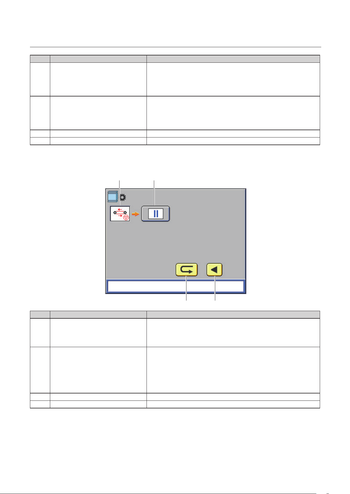
5-2. Screen menus
5-2-1. Top screen
The top screen is a screen displayed rst when you turn on the power.
Chapter 1 Before Operation
[1]
[2]
[3]
[4]
No. Name Function
Machine status Displays a current machine status. While the machine is in
[1]
Trimming mode Displays whether to perform trimming.
[2]
Finished length Displays a length of the fore-edge trimmed booklet.
[3]
Square spine display
[4]
*This is displayed when the ASM is
connected to the DBM-600T as a
downstream unit.
Processed number display Displays the number of booklets processed by the machine.
[5]
Ready
Trimming On
Fin Length
:2
operation, any of the following messages is displayed.
[Ejecting Paper] [Home Resetting] [Size Changing] [Processing] [In
Step Mode]
Displays how the Automatic SpineMaster (ASM) has been set.
: OFF: Bypass Mode
: 1: Single Pass
: 2: Double Pass (default)
To change the setting, when [Ready] is displayed as a machine
status, press the or key. When the power is turned o, the
display returns to [ : 2].
*The setting must be the same as that you made on the ASM. If the
setting is dierent between the DBM-600T and the ASM, a paper
jam or mechanical malfunction may occur.
Pressing the key for more than one second returns the count
to [0]. Once you turn o the power, the count returns to [0].
123.0
0
[5]
5-2-2. Menu list
The following menu items are provided with this machine.
Item Adjustable
range
Roller Gap -12 to +28 Adjusts roller gap by 0.5 mm/0.020 inch. You can adjust this during
operations.
*If the roller gap after adjustment is 0 mm/0 inches or less, adjustment is
not possible.
Fin Lengh -25 to +25 Adjusts nished length by 0.2 mm/0.008 inch. You can adjust this during
operations.
*If nished length is other than 75 to 307 mm/2.96 to 12.09 inches,
adjustment is not possible.
Details
1-37
Page 48

Chapter 1 Before Operation
5-2-3. How to use the menu screen
The basic operation on the menu screen is as follows.
The following steps shows how to adjust a nished length as an example.
1
Press the key when the top screen is
displayed or [Ready] or [Processing] is
displayed as a machine status.
The screen for adjusting a nished length will
be displayed.
2
Adjust a finished length using the or
key.
3
When the adjustment is complete, press
the key.
The screen returns to the top.
When other adjustment key is pressed in step
3, the adjustment screen of the pressed key is
displayed.
6. Stitching Width
Ready
Trimming On
Fin Length
Processing
Trimming On
or
123.0
0 0
Fin Length
Value
Fin Length
+0
123.0
Stitching width is the center to center distance between the two stitches. Although the stitching width has
been set to the standard position, you can change the setting if the stitch and print overlaps.
If the value you entered falls on the stitch prohibited area, the folding knife and a stitch coincide
and the folding position may slightly change. We recommend that you do not fine adjust a
stitching position and leave it as it is.
[a] Paper conveyance direction
[b] Stitching width
[c] Paper width
[a]
[b] [c]
1-38
Page 49

Chapter 1 Before Operation
• Saddle stitching and folding, saddle stitching, side stitching and folding, side stitching
Standard position = paper width/2
Example: When the paper width is 210
mm/8.27 inches
210/2 = 105 mm/4.13 inches
The available input range: 58.5 mm/2.31
inches to (paper width - 30 mm/1.18 inches)
The upper limit is 328 mm/12.91 inches.
The available input range for 2 stitches with
the 4 STITCH KIT attached: 58.5 mm/2.31
inches to (paper width - 30 mm/1.18 inches)
The upper limit is 223 mm/8.77 inches.
• Corner stitching
Standard position = 15 mm/0.59 inch (from
the lead edge of the paper to the center of the
stitch)
Example: When the paper width is 210
mm/8.27 inches
210 - 30 mm = 180 mm
/8.27 - 1.18 inches = 7.09 inches
The available input range varies depending on
the number of stitches.
4 head 4 stitches:
15 mm/0.59 inch to (paper width - 163.5
mm/6.44 inches)/2
[a] [b]
105 mm
/4.13 inches
15 mm
/0.59 inch
[a] [b]
180 mm
/7.09 inches
[c]
[c]
2 head 2 stitches:
15 mm/0.59 inch to (paper width - 58.5
mm/2.31 inches)/2
4 head 2 stitches:
If the paper width is long, stitching at 15
mm/0.59 inch from the edge of paper may
not be available. Depending on a paper
size, the minimum value changes.
1-39
Page 50

Chapter 1 Before Operation
Stitch prohibited area
The position at which the folding knife and a stitch coincide is called the stitch prohibited area. When ne
adjusting the stitching width, avoid the stitch prohibited area.
Stitch prohibited area
250 to 286 mm/9.84 to 11.26 inches
192 to 202 mm/7.56 to 7.95 inches
118 to 144 mm/4.65 to 5.67 inches
61 to 80 mm
/2.40 to 3.15 inches
Folding knife
Paper center line
Stitch prohibited area
7. Options
The items listed below are the parts for options, which a user need to attach or remove.
7-1. DBM-SSW
The DBM-SSW can be connected to both the DBM-600 and the DBM-600T.
[1] [2]
No. Name QTY Function
[1] Paper guide roller unit
(large)
[2] Paper guide roller unit
(small)
1 Holds paper conveyed to the stacker.
1 Holds paper conveyed to the stacker. Use this when a nished size of
the booklet is 121 mm/4.76 inches or less.
1-40
Page 51

Chapter 1 Before Operation
7-2. DBM-LSW
The DBM-LSW can be connected to the DBM-600T.
[1] [3][2]
No. Name QTY Function
[1] Paper guide roller unit
(large)
[2] Paper guide roller unit
(small)
[3] Paper receiving angle 2 Attach the angle to the both sides of the paper receiving tray. (magnet
1 Holds paper conveyed to the stacker.
1 Holds paper conveyed to the stacker. Use this when a nished size of
the booklet is 121 mm/4.76 inches or less.
type)
7-3. DKT-K
The DKT-K can be attached to the DBM-LSW. The DKT-K cannot be attached to the DBM-SSW.
[1] [2]
No. Name QTY Function
[1] Kicker support wheel unit 1 Attach this to the stacker.
[2] Stopper 1 Prevents the sorted booklet from being kicked too much.
(p.3-3)
(p.3-4)
1-41
Page 52

Chapter 1 Before Operation
8. Workflow
The owchart below illustrates the ow of basic operation. For details, refer to the text and relevant pages.
Turning on the power
Setting the control panel(*)
Preparing the DBM-600 and the DBM-
Preparing the upstream unit
Step mode(*)
Checking the nished booklet
Starting binding operations(*)
600T
(p.2-1)
(p.2-3)
(p.2-16)(p.2-19)
(p.2-20)
(p.2-20)
Adjusting each section
DBM-600
(p.2-25)
(p.2-48)
DBM-600T
(p.2-37)
(p.2-42)
Turning o the power
(p.2-2)
Step mode
(*) When using the PC CONTROLLER, refer to the PC CONTROLLER operation manual.
(p.2-20)
1-42
Page 53

Chapter 2 Basic Operation
1. Turning On/Off the Power
Make sure that the power plug is connected to the wall socket.
Do not touch the power switch
with wet hands.
Otherwise electric hazards may occur.
Chapter 2 Basic Operation
• When a upstream unit is connected to the DBM-600, you cannot touch the power switch. To
prevent a user from touching it, the power switch cover has been attached.
• You cannot touch the power switch of the DBM-600T. To prevent a user from touching it, the power
switch cover has been attached.
1-1. Turning on the power
Normally set the power switch to “ .”
When the power switch of the paper feeding machine (a collator or a sheet feeder) is set to “l,” the remote
function will work and turn on the power of the connected machines including this machine.
When the upstream unit is not connected to the DBM-600
1
Set the power switch of the DBM-600 to
“l.”
2-1
Page 54

Chapter 2 Basic Operation
When the upstream unit is connected to the DBM-600
1
2
Set the main power switch of the paper feeding machine to “l.”
Set the power switch of the paper feeding machine to “l.”
The remote function will work and turn on the powers of the connected machines including this
machine.
When connected to a collator, set only the power switch of the tower A to “l” and leave the power
switches of other towers “ .”
1-2. Turning off the power
When the upstream unit is not connected to the DBM-600
1
Set the power switch of the DBM-600 to
“ .”
When the upstream unit is connected to the DBM-600
1
2
Make sure that all the operations in the system are complete.
Set the power switch of the paper feeding machine to “ .”
The powers of the all the machines connected to the DBM-600 will be turned o.
Before turning on the power, wait for two seconds or more.
When connected to the collator, set the power switch of only the tower A to “ .”
When the upstream unit is connected to this machine, do not turn on/off the power using the
power switch of this machine. This may cause a malfunction. Make sure that you use the power
switch of the paper feeding machine.
2-2
Page 55

Chapter 2 Basic Operation
2. Setting the Control Panel
Make settings for a binding mode, paper size, trimming and others on the control panel. If you do not use
the default memory, select a memory number and make settings following the procedures below. All the
memories can be overwritten. It would be useful to register 20 types of settings you regularly use.
The default setting is as shown in the table below.
• When the machine is connected to the PC CONTROLLER, use the PC CONTROLLER to make settings.
You cannot make settings using this machine.
• You can make settings to prevent you from overwriting data.
• Information on memory No. 0
If you do not want to overwrite the default memory, you can save the setting you made in the
memory No. 0. The information saved in No. 0 is cleared once you turn o the power.
How to use No. 0
1) Select either one from the memories No. 1 to 20 and press the key.
2) Select the memory No. 0.
3) The detailed information on the memory you have selected in step 1) is displayed on the touch
panel.
4) Press the key.
5) Change the binding method.
6) Press the key again.
Memory
No.
1 420 x 297 16.54 x 11.69 A3 Saddle stitch Fold on
2 297 x 210 11.69 x 8.27 A4 Saddle stitch Fold on
3 210 x 297 8.27 x 11.69 A4 LEF Side stitch Fold o
4 210 x 148 8.27 x 5.83 A5 Saddle stitch Fold on
5 450 x 320 17.72 x 12.60 A3SR Saddle stitch Fold on
6 320 x 225 12.60 x 8.86 A4SR Saddle stitch Fold on
7 240 x 120 9.45 x 4.72 CD Saddle stitch Fold on
8 515 x 364 20.28 x 14.33 B3 Saddle stitch Fold on
9 364 x 257 14.33 x 10.12 B4 Saddle stitch Fold on
10 257 x 364 10.12 x 14.33 B4 LEF Side stitch Fold o
11 257 x 182 10.12 x 7.17 B5 Saddle stitch Fold on
12 182 x 257 7.17 x 10.12 B5 LEF Side stitch Fold o
13 431.8 x 279.4 17.00 x 11.00 LGR Saddle stitch Fold on
14 355.6 x 215.9 14.00 x 8.50 LGL Saddle stitch Fold on
15 215.9 x 355.6 8.50 x 14.00 LGL LEF Side stitch Fold o
16 279.4 x 215.9 11.00 x 8.50 LTR Saddle stitch Fold on
17 215.9 x 279.4 8.50 x 11.00 LTR LEF Side stitch Fold o
18 266.7 x 184.1 10.50 x 7.25 EXEC Saddle stitch Fold on
19 184.1 x 266.7 7.25 x 10.50 EXEC LEF Side stitch Fold o
20 215.9 x 139.7 8.50 x 5.50 STMT Saddle stitch Fold on
mm inch
Paper size
Standard
size
Stitch Fold
2-3
Page 56

Chapter 2 Basic Operation
2-1. Setting the standard size
Example)
Memory used: No.1
Paper size: A3 SEF (length x width 420 x 297 mm/16.54 x 11.69 inches)
Finished size: 207 x 291 mm/8.15 x 11.46 inches
Binding: saddle stitch
Folding: on
Trimming: fore-edge trimming 3 mm/0.12 inch, head/foot trimming 3 mm/0.12 inch each
1
2
3
4
Step1
Set the binding method
Press the [Main] tab.
The [Main] screen is displayed.
Select [01] using the or key.
Press the key.
The rst page of the setting screen is
displayed.
Press the saddle stitching key to set the
binding method to “saddle stitching.”
5
6
2-4
Press the folding key to set the folding
method to “folding on.”
Press the key.
Page 57

The second page of the setting screen is
displayed.
Chapter 2 Basic Operation
7
8
9
[4]
Press the fore-edge trimming key to
activate the fore-edge trimming.
Press the head/foot trimming key to
activate head/foot trimming.
Press the key.
The paper size entry screen is displayed.
Step2
Enter the paper size
[1][3]
[2]
1
2
3
Press the [1] box to enter a paper length.
The numeric entry screen is displayed.
Enter [4200] using the numeric keypad.
Press the key.
The value entered is conrmed and the paper size entry screen is displayed.
Stitching position
When a paper length is entered, the standard value from the lead edge of the paper to the stitching
position is displayed in the [3] box.
[210.0] (paper length/2) is displayed in this example.
To change the value, press the [3] box and enter a desired value using the numeric keypad.
Folding position
When a paper length is entered, the standard value from the lead edge of the paper to the folding
position is displayed in the [4] box.
[210.0] (paper length/2) is displayed in this example.
2-5
Page 58

Chapter 2 Basic Operation
To change the value, press the [4] box and enter a desired value using the numeric keypad.
4
5
6
7
Press the [2] box to enter a paper width.
The numeric entry screen is displayed.
Enter [2970] using the numeric keypad.
Press the key.
The value entered is conrmed and the paper size entry screen is displayed.
Press the key.
The nished size entry screen is displayed.
Step3
Once you enter a paper length and a paper width, the standard nished length is displayed in the [1] box
and the standard nished width in the [2] box.
Standard nished length: (nished length after folding/2) - 3 mm/0.12 inch
Standard nished width:
Enter the nished size
With head/foot trimming: (paper width - (3.0 mm/0.12 inch x 2))
Without head/foot trimming: paper width
[3]
[1] [2]
1
2
3
4
2-6
Press the [1] box to enter a finished length.
The numeric entry screen is displayed.
Enter [2070] using the numeric keypad.
Press the key.
The value entered is conrmed and the paper size entry screen is displayed.
Press the [2] box to enter a finished width.
The numeric entry screen is displayed.
Page 59

Chapter 2 Basic Operation
5
6
1
Enter [2910] using the numeric keypad.
Press the key.
The value entered is conrmed and the paper size entry screen is displayed.
Stitching width
When a nished length is entered, the standard stitching width (center to center distance between the
two stitches) is displayed in the [3] box.
[144.0] is displayed in this example.
To change the value, press the [3] box and enter a desired value using the numeric keypad.
If the value you entered falls on the stitch prohibited area, the folding knife and a stitch coincide
and the folding position may slightly change. We recommend that you do not fine adjust a
stitching position and leave it as it is.
”4-4-1. Stitch and fold setting screen” (p.1-19)
Step4
Conrm the setting
Press the key.
The information registered in the memory No.
is saved and the [Main] screen is displayed.
2
Press the key for more than one
second.
According to the settings, the guides will move.
2-2. Setting the custom size
Example)
Memory used: No.1
Paper size: length x width 500 x 297 mm/ 19.69 x 11.69 inches
Finished size: 248 x 297 mm/9.76 x 11.58 inches
Binding: saddle stitch, 4 stitches
Folding: on
Trimming: fore-edge trimming 2 mm/0.08 inch, head/foot trimming (head: 1 mm/0.04 inch, foot: 2
mm/0.08 inch)*
* You can specify oset trimming when the OFFSET TRIM KIT (option) has been attached.
2-7
Page 60

Chapter 2 Basic Operation
1
2
3
4
Step1
Set the binding method
Press the [Main] tab.
The [Main] screen is displayed.
Select [01] using the or key.
Press the key.
The rst page of the setting screen is
displayed.
Press the saddle stitching key to set the
binding method to “saddle stitching.”
5
6
7
8
9
10
Set the number of stitches to 4.
Press the folding key to set the folding
method to “folding on.”
Press the key.
The second page of the setting screen is
displayed.
Press the fore-edge trimming key to
activate the fore-edge trimming.
Press the head/foot trimming key to
activate head/foot trimming.
Press the offset trim key to activate
offset trimming.
Press the key.
11
The paper size entry screen is displayed.
2-8
Page 61

Chapter 2 Basic Operation
[4]
1
Step2
Enter the paper size
Paper size entry screen Numeric keypad
[1][3]
Press the [1] box to enter a paper length.
The numeric entry screen is displayed.
[2]
2
3
4
Enter [5000] using the numeric keypad.
Press the key.
The value entered is conrmed and the paper size entry screen is displayed.
Stitching position
When a paper length is entered, the standard value from the lead edge of the paper to the stitching
position is displayed in the [3] box.
[250.0] (paper length/2) is displayed in this example.
To change the value, press the [3] box and enter a desired value using the numeric keypad.
Folding position
When a paper length is entered, the standard value from the lead edge of the paper to the folding
position is displayed in the [4] box.
[250.0] (paper length/2) is displayed in this example.
To change the value, press the [4] box and enter a desired value using the numeric keypad.
Press the [2] box to enter a paper width.
The numeric entry screen is displayed.
5
6
7
Enter [2970] using the numeric keypad.
Press the key.
The value entered is conrmed and the paper size entry screen is displayed.
Press the key.
The nished size entry screen is displayed.
2-9
Page 62

Chapter 2 Basic Operation
Step3
Once you enter a paper length and a paper width, the standard nished length is displayed in the [1] box
and the standard nished width in the [2] box.
Standard nished length: (nished length after folding/2) - 3 mm/0.12 inch
Standard nished width:
Enter the nished size
With head/foot trimming: (paper width - (3.0 mm/0.12 inch x 2))
Without head/foot trimming: paper width
Finished size entry screen Numeric keypad
[1] [2][3]
1
2
3
4
5
6
7
8
Press the [1] box to enter a finished length.
The numeric entry screen is displayed.
Enter [2480] using the numeric keypad.
Press the key.
The value entered is conrmed and the paper size entry screen is displayed.
Press the [2] box to enter a finished width.
The numeric entry screen is displayed.
Enter [2940] using the numeric keypad.
Press the key.
The value entered is conrmed and the paper size entry screen is displayed.
To enter the head/foot trimming width, press the [3] box.
The numeric entry screen is displayed.
Enter [1].
9
2-10
Press the key.
The value entered is conrmed and the paper size entry screen is displayed.
Page 63

Chapter 2 Basic Operation
Stitching width
[1]
[2]
When the 4 STITCH KIT (option) has been installed, the stitching width is displayed in [1] and [2].
[1]: Stitching width for the two stitches on the operator’s side and the other two stitches on the
non-operator’s side
[2]: Stitching width for the two inside stitches
According to the paper size entered, a standard value is displayed in each box. You can also change the
value.
Setting range:
• 2 stitches: 58.5 to (paper width - 30) mm/2.31 to (paper width - 1.18) inches*
*The upper limit is 328 mm/12.91 inches.
• 4 head 2 stitches: 58.5 to (paper width - 30) mm/2.31 to (paper width - 1.18) inches*
Default: paper length/2
*The upper limit is 223 mm/8.77 inches
• 4 head 4 stitches (inside): 58.5 to (paper width - (stitching width outside x 2) - 30) mm
/2.07 to (paper width - (stitching width outside x 2) - 1.18 inches*
A default value varies depending on the paper size.
*The upper limit is 223 mm/8.77 inches when the stitching width outside is 52.5 mm/2.07 inches
• 4 head 4 stitches (outside): 52.5 to (paper width - 58.5 - 30)/2*
A default value varies depending on the paper size.
*The upper limit is 134.7 mm/5.30 inches when the stitching width inside is 58.5 mm/2.31 inches.
If the standard position falls on the stitch prohibited area, the value that avoids the stitch prohibited
area will be automatically set.
2-11
Page 64

Chapter 2 Basic Operation
Step4
1
2
””2-2-2. Adjusting the stitching side guides and the folding side guides (option)” (p.2-14)
Conrm the setting
Press the key.
The information registered in the memory No. is saved and the [Main] screen is displayed.
Press the key for more than one second.
The screen for the oset trim amount is displayed.
If you have not selected oset trimming when the OFFSET TRIM KIT is attached, move the stitching
side guides and the folding side guides of the DBM-600 inward.
[1]
[3]
[4]
[2]
[5]
No. Name Function
3
Oset adjustment value for head/foot
[1]
trimming (head)
Oset adjustment value for head/foot
[2]
trimming (foot)
DBM-600 oset adjustment value
[3]
(head)
DBM-600 oset adjustment value (foot) The oset adjustment value (foot) for the DBM-600 is displayed.
[4]
Message display [Adjust the head/foot guide position manually.] is displayed.
[5]
According to the value displayed in [1] to [4] on the screen, move the head/foot guides
The oset adjustment value (head) for the DKT-200 is displayed.
Setting range: 0 to 21
The oset adjustment value (foot) for the DKT-200 is displayed.
Setting range: 0 to 21
The oset adjustment value (head) for the DBM-600 is displayed.
Setting range: 0 to 21
Setting range: 0 to 21
of the DKT-200 and the stitching side guides and the folding side guides of the DBM-
600.
””2-2-1. Adjusting head/foot guide of the DKT-200” (p.2-13) ““2-2-2. Adjusting the stitching side guides and the folding side guides (option)”
(p.2-14)
4
2-12
After moving the guides, press the key for more than one second.
According to the settings, the guides will move.
Page 65

Chapter 2 Basic Operation
2-2-1. Adjusting head/foot guide of the DKT-200
Before following the procedures below, turn off the power switch of this machine referring
to the procedures in ”1-2. Turning off the power"
machine from the wall outlet.
(p.2-2)
and disconnect the power cords of this
1
2
3
Open the top cover of the DKT-200.
Insert the L-handle into the knob screw of the adjustment dial of the head/foot guide.
Knob screw
Head
Foot
Turn the L-handle counterclockwise to
loosen the knob screw.
If you turn the knob screw too much, it will
come off the machine.
Knob screw
4
5
6
7
Remove the L-handle from the knob screw.
Check the value shown in the screen of step 2 in“Step4 Confirm the setting” (p.2-7) and
move the adjustment dial to align the indicator with the value.
Moving one division changes the trimming width in 1 mm/0.04 inch increments. If you cannot see the
dial, close the top cover, and then press and hold the home resetting key of the DKT-200. The head/
foot guide returns to its original position.
If you did not remove the L-handle from the knob screw in step 4, the head/foot guide may hit
or touch the L-handle when the guide returns to its original position. Be sure to remove the
L-handle from the knob screw in step 4.
Turn the knob screw of the adjustment dial of the head/foot guide clockwise by hand to
tighten it temporarily.
Insert the L-handle into the knob screw of the adjustment dial.
2-13
Page 66

Chapter 2 Basic Operation
8
9
10
Turn the L-handle clockwise to fully tighten the knob screw.
Make sure that you use the L-handle to fully tighten the knob screw. If you tighten the knob
screw just by hand, the knob screw may not be tightened enough.
Remove the L-handle from the knob screw.
Once you change the trimming width on the PC CONTROLLER, repeat procedures described previously
to adjust the head/foot guide.
Close the top cover of the DKT-200.
When you do not perform offset trimming, return the adjustment dial to the “0” position.
2-2-2. Adjusting the stitching side guides and the folding side guides (option)
•
Do not disassemble the
product more than needs.
Fire, electrication, injury,
malfunction, or breakdown may
be caused by disassembling the
parts which are not specied in
this manual.
• Do not use the L-wrench for purposes other than instructed in this manual.
• Before following the procedures below, turn off the power switch of this machine referring
to the procedures in ”1-2. Turning off the power”
machine from the wall outlet.
If you wish to change the stitching width to other than the default, follow the procedures below
rst. When the paper is large and the stitching width is wide, it will be dicult for you to follow the
procedures.
1
2
3
Open the top cover of the DBM-600.
Insert the L-wrench to the fixing screw on each stitching side guide.
Turn the L-wrench counterclockwise to loosen the fixing screw.
Fixing screw for the side guide
(p.2-2)
and disconnect the power cords of this
Foot
Head
2-14
Page 67

Chapter 2 Basic Operation
4
5
6
7
Move the stitching side guides manually
to the position of the value displayed
on the control panel referring to the
scale label.
Each mark on the scale indicates a 1 mm/0.04
inch increment.
When moving the side guides, hold the area
marked with the green triangle.
If you move the guides holding the other
area, the guides may be deformed.
Insert the L-wrench to the fixing screw
on each stitching side guide.
Turn the L-wrench clockwise to tighten the fixing screw.
Loosen the fixing screw on each folding side guide.
8
9
Foot
Move the folding side guides manually
to the position of the value displayed
on the control panel referring to the
scale label.
Each mark on the scale indicates a 1 mm/0.04
inch increment.
When moving the side guides, hold the area
marked with the green triangle.
If you move the guides holding the other
area, the guides may be deformed.
Tighten the fixing screw on each folding side guide.
Head
When you not perform offset trimming, return the stitching side guides and the folding side
guides to the “0” position.
2-15
Page 68

Chapter 2 Basic Operation
3. Preparing the DBM-600 for Operation
3-1. Using the paper guide
Use the supplied paper guide for side stitching,
corner stitching, and side stitching/folding.
1
2
3
4
5
Loosen the knob screw of the paper
guide attached to the machine.
Remove the paper guide.
Attach the supplied paper guide.
Insert the two notches into the screws
as shown in the figure.
Tighten the knob screw of the paper
guide.
3-2. Attaching the parts for page insertion
3-2-1. Attaching the page insertion roller
When performing page insertion, replace the sidestitching ejection rollers with the supplied page
insertion rollers.
1
Loosen the knob screw of the sidestitching ejection roller completely.
2
3
4
5
2-16
Lift the folding stopper unit.
Pull the side-stitching ejection roller
toward you to remove it.
Align the notch of the page insertion
roller with the shaft.
Tighten the knob screw.
Once you nish the page insertion operations,
remove the page insertion rollers and attach
the side-stitching ejection rollers.
Page 69

3-2-2. Attaching the page insertion guide
Chapter 2 Basic Operation
1
2
Align the left notch on the page
insertion guide with the hole on the
machine.
Align the right notch on the page
insertion guide with the cutout on the
machine.
Once you nish the page insertion operations,
remove the page insertion guide.
3-3. Moving the stitch release levers (for corner stitching)
When performing corner stitching, follow the
procedure below.
• While lifting the stitch release lever of the
stitcher head that is not used for the corner
stitching, move it to the operator’s side.
• Set the wire feed detection for the side that
is not used for corner stitching to off.
(p.1-29)
3-4.
A stitched booklet is ejected to the paper receiver for side stitching and corner stitching. Move the paper
receiver stopper according to the paper size.
1
2
3
Adjusting the paper receiver stopper (for side stitching, corner stitching)
Loosen the paper receiver knob screw.
Move the stopper manually referring to
the scale label.
Tighten the paper receiver knob screw.
2-17
Page 70

Chapter 2 Basic Operation
3-5. Aligning the paper passage lines
After preparing this machine for binding operations,
check that the paper passage line is aligned to that
of the upstream unit.
When paper conveyed from the upstream unit is
sent to this machine, check that there is even space
between the left and right side guides and paper.
If not even, adjust the position to avoid paper jams
following the procedures below.
1
2
3
4
Press the [Adjust] tab.
The [Adjust] screen is displayed.
Press the base adjustment screen.
The base adjustment screen is displayed.
Adjust the position of this machine
using the or key to make even
space between the left and right side
guides and paper.
Press the return key.
The [Adjust] screen is displayed.
2-18
Page 71

Chapter 2 Basic Operation
4. Preparing the DBM-600T for Operation
If the trimming width is 25 mm/0.98 inch or longer, follow the procedures below before trimming.
1
2
3
1
Loosen the infeed roller unit knob
screw.
While lifting the infeed roller unit, move
the angle to the non-operator’s side to
place the infeed roller unit on the angle.
Tighten the infeed roller unit knob
screw.
When paper jams
After the infeed roller unit is raised, a paper jam may occur or a booklet may stop under the infeed roller
unit. In that case, widen the roller gap.
Press the key when [Ready] or
[Processing] is displayed as a machine
status.
The screen for adjusting a roller gap will be
displayed.
Ready
Trimming On
Fin Length
Processing
Trimming On
or
123.0
0 0
Fin Length
123.0
2
3
Narrow the roller gap using the key.
When the adjustment is complete, press
the key or key.
The screen returns to the top.
If the problem is not solved, follow the procedures below.
1) Remove the infeed roller unit.
””B. When you cannot remove a booklet” (p.5-9)
2) Loosen the support roller knob screw and
move it downward.
The support rollers will be lowered.
3) Tighten the support roller knob screw.
4) Put back the infeed roller unit to its original
place.
Roller Gap
Value
+0
2-19
Page 72

Chapter 2 Basic Operation
5. Making the Upstream Unit Ready
Prepare the upstream unit for starting operations, such as setting the control panel. For details, refer to the
instruction manual of the upstream unit.
6. Adjusting Each Section (Step Mode)
Before starting a binding operation, adjust each section in the step mode. The adjusted value in the step
mode is saved in the memory you are currently using.
• When fore-edge trimming or head/foot trimming has been set to on, you can specify whether to
trim paper in the step mode.
• The booklet made in the step mode is not counted as the number of sets processed.
• When using the PC CONTROLLER, you can perform the step mode using the PC CONTROLLER. For
details, refer to the PC CONTROLLER operation manual.
6-1. Starting the step mode
1
2
3
Press the [Adjust] tab.
When fore-edge trimming or head/foot
trimming has been set to on, press the
trimming on/off key to select whether
to activate trimming during the step
mode.
Each time you press the key, trimming is
switched between on and o.
O: the key is displayed in grey.
On: the key is displayed in green
When using the PC CONTROLLER , make setting on the PC CONTROLLER.
Press the step mode key.
The stitching section adjustment screen will
be displayed.
When the binding method has been set to
page insertion, the folding section adjustment
screen is displayed.
2-20
Page 73

Pressing the key of the upstream unit or the
DBM-600, a set of paper will be conveyed from the
upstream unit to the stitching section and stop
there.
Press the key to stop the step mode in the middle.
To remove paper left inside the machine, open the
top cover.
When the PC CONTROLLER is connected,
you can perform the step operations only
for the DBM-600 (separate step mode). For
details, refer to the PC CONTROLLER operation
manual.
On the other hand, when the PC CONTROLLER
is not connected, the step mode is performed
for the DBM-600 and its downstream units.
Chapter 2 Basic Operation
6-2. Adjusting the stitching section (when “stitching on” has been selected)
[12] [13] [14] [15]
[1] [2][3] [4]
[5]
[10]
[6]
[7]
[16]
[11]
No. Items Function
[1] Fine adjustment of stitching side
guides
[2] The stitching side guides move outward by about 1.0 mm/0.039 inch.
[3] The stitching side guides move inward by about 0.20 mm/0.008 inch.
[4] The stitching side guides move outward by about 0.20 mm/0.008
[5] Stitching side guide operations Activates the stitching side guides once.
The stitching side guides move inward by about 1.0 mm/0.039 inch.
inch.
[8] [9]
2-21
Page 74

Chapter 2 Basic Operation
No. Items Function
[6] Fine adjustment of stitching back
guide
[7] The stitching back guide moves forward by about 0.99 mm/0.039
[8] The stitching back guide moves backward by about 0.09 mm/0.004
[9] The stitching back guide moves forward by about 0.09 mm/0.004
[10] Stitching back guide operations Activates the stitching back guide once.
[11] Stitch key Stitches a set. The booklet is conveyed to the folding stopper and
[12] Stitching side guide ne adjustment
value (parameter)
[13] Stitching side guide ne adjustment
value (actual value)
[14] Stitching back guide ne adjustment
value (parameter)
[15] Stitching back guide ne adjustment
value (actual value)
[16] Message display Waiting: no message
The stitching back guide moves backward by about 0.99 mm/0.039
inch.
inch.
inch.
inch.
stops. When folding has been set to o, the booklet is ejected to the
paper receiver and the step mode ends.
Displays a parameter of the ne adjustment value for the stitching
side guide.
Adjustable range: -25 to 25
Displays an actual value of the ne adjustment value for the stitching
side guide.
Adjustable range: -5.0 to 5.0 mm/-0.197 to 0.197 inch
Displays a parameter of the ne adjustment value for the stitching
back guide.
Adjustable range: -55 to 55
Displays an actual value of the ne adjustment value for the stitching
back guide.
Adjustable range: -4.95 to 4.95 mm/-0.195 to 0.195 inch
Starting: [Starting]
In step mode: [Active]
Guides are moving: [Processing]
Adjust the positions of the stitching side guides
using the keys [1] to [4] and the stitching back guide
using the keys [6] to [9].
Perform jogging using keys [5] and [10].
Adjust so that the guides touch the booklet edges
lightly.
2-22
Page 75

Chapter 2 Basic Operation
After adjustment, press the key [11]. The paper is
stitched and goes to the folding stopper.
• When stitching has been set to o, the paper
goes to the folding stopper without being
stitched.
• When side stitching, corner stitching and
folding o have been selected, the paper is
ejected to the paper receiver.
Fine adjustments can be performed only within the range of ±5 mm/0.20 inch after size change.
If the paper size entered and that actually used differ by more than 5 mm/0.20 inch, you may
not be able to adjust precisely. Depending on the paper size, adjustment even within the range
of ±5 mm/0.20 inch may not be possible. In this case, enter the correct paper size again, and
perform the size change.
6-3.
Adjusting the folding section (when “folding on” has been selected)
[12] [13] [14] [15]
[1] [2][3] [4]
[5]
[10]
[6]
[7]
[16]
[11]
[8] [9]
Adjust the position of the folding side guides using keys [1] to [4] and the folding back guides using the keys [6]
to [9].
Perform jogging using keys [5] and [10].
Adjust so that the guides touch the booklet edges lightly.
After adjustment, press the key [11]. The paper is folded and ejected, and the step mode ends.
When trimming is set to on using the trimming on/o key before starting the step mode, a booklet is
trimmed and ejected.
No. Items Function
[1] Fine adjustment of folding side guide The folding side guides move inward by about 1.0 mm/0.039 inch.
[2] The folding side guides move outward by about 1.0 mm/0.039 inch.
[3] The folding side guides move inward by about 0.20 mm/0.008 inch.
[4] The folding side guides move outward by about 0.20 mm/0.008 inch.
[5] Folding side guides operations Activates the folding side guides once.
2-23
Page 76

Chapter 2 Basic Operation
No. Items Function
[6] Fine adjustment of folding back guide The folding back guide moves backward by about 0.90 mm/0.035
inch.
[7] The folding back guide moves forward by about 0.90 mm/0.035 inch.
[8] The folding back guide moves backward by about 0.18 mm/0.007
inch.
[9] The folding back guide moves forward by about 0.18 mm/0.007 inch.
[10] Folding back guide operations Activates the folding back guide once.
[11] Folding key A booklet is folded. After the booklet is ejected, the step mode ends
and the [Adjust] screen is displayed.
[12] Folding side guide ne adjustment
value (parameter)
[13] Folding side guide ne adjustment
value (actual value)
[14] Folding back guide ne adjustment
value (parameter)
[15] Folding back guide ne adjustment
value (actual value)
[16] Message display Ready: no message
Displays a parameter of the ne adjustment value for the folding side
guide.
Adjustable range: -25 to 25
Displays an actual value of the ne adjustment value for the folding
side guide.
Adjustable range: -5.0 to 5.0 mm/-0.197 to 0.197 inch
Displays a parameter of the ne adjustment value for the folding
back guide.
Adjustable range: -27 to 27
Displays an actual value of the ne adjustment value for the folding
back guide.
Adjustable range: -4.86 to 4.86 mm/-0.191 to 0.191 inch
Starting: [Starting]
In step mode: [Active]
Guides are moving: [Processing]
Fine adjustments can be performed only within the range of ±5 mm/0.20 inch after size change.
If the paper size entered and that actually used differ by more than 5 mm/0.20 inch, you may
not be able to adjust precisely. Depending on the paper size, adjustment even within the range
of ±5 mm/0.20 inch may not be possible. In this case, enter the correct paper size again, and
perform the size change.
2-24
Page 77

Chapter 2 Basic Operation
6-4. Adjusting the trimming section (when “trimming on” has been selected)
After the step mode is complete in the DBM-600, a booklet stops at the stopper of the DBM-600T. If
necessary, make the following adjustments.
1
Set the trimming for the step mode to on to adjust the trimming section
fore-edge trimming is not performed.
Check that the paper touches the
stopper.
If not, adjust the conveyance stop timing on
the control panel of the DBM-600
CONTROLLER.
(p.1-34)
or the PC
(p.2-20)
. When set to off,
2
3
Press the key.
The fore-edge of the booklet is trimmed and
sent to the stacker or the downstream unit.
Check the finished booklet.
””7. Checking Finished Booklets” (p.2-25)
Performing step mode only for the DBM-600T
To perform the step mode only for the DBM-600T, perform the separate step mode.
””5-1. Names of control panel” (p.1-36)
7. Checking Finished Booklets
Check the binding state of the booklets made using the step mode.
7-1. When paper does not align
When paper alignment is poor, adjust the stitching side guides, stitching back guide, folding side guides or
folding back guide and increase the number of jogs.
2-25
Page 78

Chapter 2 Basic Operation
7-1-1. Adjusting the guides position
The sheets of paper are not
aligned along the length.
It is necessary to adjust the
back guide.
The procedures below describe how to adjust the stitching side guides.
1
Press the stitching side guide
The sheets of paper are
not aligned along the side.
It is necessary to adjust the
side guides.
adjustment key on the [Adjust] screen.
The sheets of paper are not
aligned along the length and side.
It is necessary to adjust both the
back guide and the side guides.
2
The stitching side guide adjustment screen is
displayed.
Press any of the key between [3] and [6]
to adjust the stitching side guides.
[1] Current setting value is displayed as a
parameter.
Setting range: -25 to 25, default: 0
[2] The current stitching position is displayed
in mm/inch.
Setting range: -5.0 to 5.0 mm/-0.197 to
0.197 inch, default: 0
[3] The distance between the stitching side
guides becomes shorter by approx 1.0
mm/0.039 inch.
[4] The distance between the stitching side
guides becomes shorter by approx 0.2
mm/0.008 inch.
[5] The distance between the stitching side
guides becomes longer by approx. 0.2
mm/0.008 inch.
[6] The distance between the stitching side
[3]
[1]
[4] [5] [6] [7]
[2]
2-26
Page 79

guides becomes longer by approx. 1.0
mm/0.039 inch.
[7] Pressing this returns to the [Adjust] screen.
Adjust the stitching back guide, folding side
guides and folding back guide in the same
way.
7-1-2. Increasing the number of jogs
Chapter 2 Basic Operation
1
Display the third page (3/7) of the
[Function] screen.
2
Press the + key to increase the number
of jogs for the stitching section.
7-2. When stitching and folding positions do not align
Correct example
The folded line and stitched
position are aligned.
The folded line is
slightly deviated above
the stitched position.
The folded line is slightly
deviated below the stitched
position.
1
Paper ejection
direction
Fine adjust the stitching position
or folding position.
Press the stitching position adjustment
key on the [Adjust] screen.
Fine adjust the stitching position
or folding position.
2-27
Page 80

Chapter 2 Basic Operation
The stitching position adjustment screen is
displayed.
[1]
[2]
2
3
Press any of the key between [3] and [6]
to adjust the stitching position.
[1] Current setting value is displayed as a
parameter.
Setting range: -55 to 55, default: 0
[2] The current stitching position is displayed
in mm/inch.
Setting range: -4.95 to 4.95 mm/-0.195 to
0.195 inch, default: 0
[3] The stitching position moves forward by
approx. 0.99 mm/0.039 inch.
[4] The stitching position moves forward by
approx. 0.09 mm/0.004 inch.
[5] The stitching position moves backward by
approx. 0.09 mm/0.004 inch.
[6] The stitching position moves backward by
approx. 0.99 mm/0.039 inch.
[7] Pressing this returns to the [Adjust] screen.
Press the folding position adjustment
key on the [Adjust] screen.
[3]
[4] [5] [6] [7]
4
The folding position adjustment screen is
displayed.
Press any of the key between [3] and [6]
to adjust the folding position.
[1] Current setting value is displayed as a
parameter.
Setting range: -27 to 27, default: 0
[2] The current setting value is displayed in
mm/inch.
Setting range: -4.86 to 4.86 mm/-0.191 to
0.191 inch, default: 0
[3] The folding position moves forward by
approx. 0.90 mm/0.035 inch.
[4] The folding position moves forward by
approx. 0.18 mm/0.007 inch.
[5] The folding position moves backward by
approx. 0.18 mm/0.007 inch.
[6] The folding position moves backward by
approx. 0.90 mm/0.035 inch.
[7] Pressing this returns to the [Adjust] screen.
[3]
[1]
[4] [5] [6] [7]
[2]
2-28
Page 81

Chapter 2 Basic Operation
7-3. Adjusting stitching and folding positions simultaneously
Correct example
The stitched/folded line is at
the center of the paper.
1
Press the stitching and folding position
adjustment key on the [Adjust] screen.
The stitching and folding position adjustment
screen will be displayed.
Paper ejection
direction
The stitched/folded line is
out of position and the top
half of the paper is shorter.
Misalignment
The stitched/folded line is out
of position and the bottom
half of the paper is shorter.
Misalignment
[1]
[2]
2
Press any of the key between [3] and [6]
to adjust the folding position.
Refer to the following procedures for the
setting range.
Stitching position
step 2 in””7-2. When stitching and folding
positions do not align” (p.2-27)
Folding position
step 4 in””7-2. When stitching and folding
positions do not align” (p.2-27)
[3]
[4] [5] [6] [7]
2-29
Page 82

Chapter 2 Basic Operation
7-4. Adjusting the stitching width
Although the stitching width is automatically set to the standard position, you can change it if a stitch and
prints coincide.
””6. Stitching Width” (p.1-38)
1
2
Press the stitching width adjustment
key on the [Adjust] screen.
The stitching width adjustment screen is
displayed.
Press any of the key between [3] and [6]
to adjust the stitching width.
[1] Current setting value is displayed as a
parameter.
Setting range: -50 to 50, default: 0
[2] The current setting value is displayed in
mm/inch.
Setting range: -5.00 to 5.00 mm/-0.197 to
0.197 inch, default: 0
[3] The distance between the two stitches
becomes shorter by approx 1.0 mm/0.039
inch.
[4] The distance between the two stitches
becomes shorter by approx 0.1 mm/0.004
inch.
[5] The distance between the two stitches
becomes longer by approx. 0.1 mm/0.004
inch.
[6] The distance between the two stitches
becomes longer by approx. 1.0 mm/0.039
inch.
[7] Pressing this returns to the [Adjust] screen.
[3]
[1]
[4] [5] [6] [7]
[2]
For 4 stitches
When using the 4 STITCH KIT (option), adjust
[1] stitching width (inside), [2] stitching width
(outside), and [3] stitching width (inside and
outside) in the way previously described.
2-30
[1] [2] [3]
Page 83

Chapter 2 Basic Operation
7-5. When fold is skewed
When fold is skewed, adjust the angle of the folding side guides using the fold misalignment adjustment
1
2
3
Turn the fold misalignment adjustment
knob screw counterclockwise to loosen
it.
Adjust the angle of the stopper using
the folding stopper angle adjustment.
The condition of booklets
Turn the adjustment clockwise.
Turn the adjustment counterclockwise.
Turn the fold misalignment adjustment
knob screw clockwise to tighten it.
• If the stitching position is inside the stitching
prohibited area shown on the stitching
position label, folding misalignment may
occur. Change the stitching width using the
stitching width key on the [Adjust] screen and
adjust so that it is outside this area.
• Folding misalignment may also occur if the
folding side guides are set too narrow or wide.
Perform adjustments in the step mode again,
and check the position of the folding side
guides or the folding back guides.
• If the booklet rides onto the folding side
guide or jams, gradually increase the value
of “stitching side guide open timing” on the
[Function] screen. The standard value is 0.
However, paper may jam at the stitching
section if too many sheets of paper are fed.
2-31
Page 84

Chapter 2 Basic Operation
7-6. When the stitching position is not at right angle to paper
Do not disassemble the
product more than needs.
Fire, electrication, injury,
malfunction, or breakdown may
be caused by disassembling the
parts which are not specied in
this manual.
• Do not use the L-wrench for purposes other than instructed in this manual.
• Before following the procedures below, turn off the power switch of this machine referring
to the procedures in ”1-2. Turning off the power”
machine from the wall outlet.
If the stitches are not at right angle with paper, adjust the angle of the saddle-stitching stopper and the
stitching side guides.
(p.2-2)
and disconnect the power cords of this
1
2
3
Move the saddle-stitching stopper lock
plate to the operator’s side to release
the lock.
Turn the saddle-stitching stopper angle
adjustment according to the state of the
stitches.
For the condition shown in the gure A, turn
the adjustment counterclockwise.
For the condition shown in the gure B, turn
the adjustment clockwise.
A B
After adjustments, align the slits of
the saddle-stitching stopper angle
adjustment with the saddle-stitching
stopper lock plate as shown in the
figure.
After completing the angle adjustment of the
saddle-stitching stoppers, adjust angle of the
stitching side guides. Make adjustment while
checking the state of the paper in the step
mode.
2-32
Page 85

Chapter 2 Basic Operation
4
5
6
7
8
Loosen the stitching side guide knob
screws.
When the OFFSET TRIM KIT (option) is
attached, loosen the fixing screw on
each stitching side guide using the
L-wrench.
Turn the stitching side guide
adjustment to adjust the angle.
Tighten the stitching side guide knob
screws.
When the OFFSET TRIM KIT (option)
is attached, tighten the fixing screw
on each stitching side guide using the
L-wrench.
””2-2-2. Adjusting the stitching side guides and the folding side guides (option)” (p.2-14)
7-7. When paper does not align on the belt stacker
• Change the conveyance time of the belt stacker on the [Options] screen.
If there are too many sheets, or when paper is thick, make the conveyance time longer.
• If booklet alignment is still poor after adjusting the conveyance time, replace the paper guide roller with
the one for large size paper. However, this cannot be used for a booklet whose nished size is 121 mm/4.76
inches or less.
• If booklet alignment is still poor, loosen the knob screw and move the paper guide roller to the main body.
2-33
Page 86

Chapter 2 Basic Operation
7-8. When there is a scratch on a booklet
When there is a scratch on the surface of a booklet, attach the guide 1 unit, guide 2 unit, and guide 3 unit,
the angle F unit, and the angle B unit.
Step1
Attach the guide 1 unit, guide 2 unit, and guide 3 unit to the DBM-600.
1
2
Attaching the guide 1, 2 and 3 units
Align the notches of the guide 1 unit
with the holes in the folding section.
Align the notch of the guide 2 unit with
the hole in the folding section.
Paper conveyance direction
Guide 2 unit
Paper conveyance direction
Guide 1 unit
Guide 2 unit
Guide 2 unit
3
Align the notches of the guide 3 units
with the holes in the infeed section.
Guide 3 unit
Paper conveyance
direction
Guide 3 unit
Paper conveyance
direction
Guide 3 unit
2-34
Page 87

Chapter 2 Basic Operation
1
2
Step2
Attaching the angle F and B units
While releasing the Infeed conveyance
unit lock lever, lift the infeed
conveyance unit.
Remove the stitching ejection roller R
unit.
3
Attach the angle F and B units aligning
the holes with the screws on the
machine as shown in the figure.
When the paper size is small, specify the larger
size to make the guides open widely, which
will enable you to easily attach the units.
2-35
Page 88

Chapter 2 Basic Operation
7-9. Stripping occurs on the surface of a booklet
7-9-1. Adjusting the fold ejection roller gap adjustment lever
Adjust the position of the fold ejection roller gap adjustment lever. Set the lever to the same position on
either side. If the position is not the same, a folding misalignment may occur.
Standard position: right viewing from the operator’s side
1
2
3
Loosen the fold ejection roller gap knob
screw.
Move the lever to the left.
Move the lever to the left until it stops.
Tighten the fold ejection roller gap
knob screw.
7-9-2. Adjusting the press roller gap
When stripping occurs on the surface of a booklet, narrow the press roller gap. Set the lever to the same
position on either side. If the position is not the same, a folding misalignment may occur.
Standard position: [a]
1
2
3
4
5
2-36
Remove the pressure adjustment lever
from the pin.
Loosen the press roller gap fixing lever.
Move the press roller gap adjustment
lever to either [b] or [c].
Tighten the press roller gap fixing lever.
Attach the pressure adjustment lever to
the pin.
[a]
[b]
[c]
Page 89

Chapter 2 Basic Operation
8. Adjusting Each Part (DBM-600)
8-1. Adjusting the infeed paper holder
When paper is thin and the total number of sheets is small, paper may bend because it knocks against the
infeed paper holder. In this case, make the following adjustment.
1
2
3
Loosen the infeed paper holder knob
screws.
Move the bracket of the infeed paper
holder in the direction of the arrow
shown in the figure.
Checking the conveyance condition, move the
bracket little by little.
Tighten the infeed paper holder knob
screw.
8-2. Adjusting the stitching paper holder
If the gap between the stitching paper holder and the conveyance guide is not appropriate for the paper
thickness, paper jam or stitch misalignment may occur. In this case, make the following adjustment.
Standard position: [a] is set in the top hole as shown in the gure.
1
Loosen the stitching paper holder knob
screw.
2
3
Adjust the position of the stitching
paper holder.
When paper knocks against the stitching
paper holder, move the holder upward.
When paper sags in the gap between the
stitching paper holder and the guide plate:,
move the holder downward.
Tighten the stitching paper holder knob
screw.
[a]
2-37
Page 90

Chapter 2 Basic Operation
8-3. Adjusting the height of the stitch ejection roller R
When paper is large or the number of sheets is large, paper may not reach the folding section because it is
slowly conveyed to the folding section from the stitching section. Adjust the height of the stitch ejection
roller R.
Standard position: top
1
2
3
Loosen the stitch ejection roller R knob
screw.
Turn the stitch ejection roller R height
adjustment clockwise.
The roller goes down.
Tighten the stitch ejection roller R knob
screw.
8-4. Adjusting the folding roller gap
If a booklet jams in the folding section, the gap between the folding rollers (folding roller gap) may be too
wide for the paper thickness. Adjust the folding roller gap on the control panel.
1
Press the roller gap adjustment key on
the [Adjust] screen.
2
2-38
The folding roller gap adjustment screen is
displayed.
Press [4] or [5] to adjust the folding
roller gap.
[1] Current setting value is displayed as a
parameter.
Setting range: -45 to 45, default: 0
[2] The current value is displayed in mm/inch.
Setting range: -5.85 to 5.85 mm/-0.23 to
0.23 inch, default: 0
[3] The colored range on the bar shows the
proportion of the total setting value.
[4] The folding roller gap becomes narrower
by approx 0.13 mm/0.005 inch.
[5] The folding roller gap becomes wider by
approx 0.13 mm/0.005 inch.
[1]
[2]
[4]
[3]
[5]
[6]
Page 91

Chapter 2 Basic Operation
[6] Pressing this returns to the [Adjust] screen.
8-5. Adjusting the height of the insertion roller
When a sheet for page insertion does not reach the folding stopper or strike against it during page insertion
operations, adjust the height of the page insertion roller.
Standard position: Tuned fully counterclockwise
1
2
3
Loosen the page insertion roller knob
screw.
Turn the page insertion roller height
adjustment to adjust the height of the
roller.
When paper does not reach the folding
stopper: Turn it counterclockwise. The rollers
move downward.
When paper strikes against the folding
stopper: Turn it clockwise. The rollers move
upward.
For side stitching and corner stitching, set the
page insertion roller height adjustment to the
standard position.
Tighten the page insertion roller knob
screw.
8-6. Adjusting the pressure adjustment lever
When a booklet does not get caught in a press roller when folded or it is ejected skewed from the press
roller, set the levers to “3.” Set the lever to the same position on either side. If the position is not the same, a
folding misalignment may occur.
Standard position: 2
1
2
Remove the pressure adjustment lever
from the pin.
Change the position of the hole on the
pressure adjustment lever.
If the problem is not solved by setting the
lever to “3,” change it to “4.”
1
2
3
4
2-39
Page 92

Chapter 2 Basic Operation
8-7. Using the fold paper holder
When thin paper sags in the folding section, use the fold paper holder. Set the adjustment to the same
position on either side.
Standard position: [B]
1
2
Loosen the fold paper holder knob
screw.
Move the fold paper holder height
adjustment counterclockwise.
Standard position: [B]
Counterclockwise: The fold paper holder
moves downward and the gap becomes
narrower. [A]
Clockwise: The fold paper holder moves
upward and the gap becomes wider. [B]
[A] [B]
8-8. Adjusting the ejection pressure
When a booklet conveyed from the folding section is not ejected smoothly, change the position of the
ejection pressure adjustment lever. Set the lever to the same position on either side.
Standard position: lower
1
2
Remove the ejection pressure
adjustment lever from the pin.
Move the lever to the upper position.
2-40
Page 93

Chapter 2 Basic Operation
8-9. Using the paper receiving guides F and B
During side stitching operations, if the sides of paper do not align on the paper receiver, use the supplied
paper receiving guides F and B.
Place the paper receiving guides F and
B at 10 mm/0.39 inch from each side of
paper.
Place the paper receiving guide F on the
operator’s side and the paper receiving guide
B on the non-operator’s side.
10 mm/0.39 inch
10 mm/0.39 inch
8-10. Using the paper guide bracket
During side stitching operations, if paper is not neatly stacked on the paper receiver, use the supplied paper
guide bracket.
Place the paper guide bracket on the
right edge of the paper receiver when
viewing from the operator’s side.
Align the bent part of the guide with the
paper receiver.
2-41
Page 94

Chapter 2 Basic Operation
8-11. Adjusting the height of the paper receiver full loading sensor
In the following cases, move the paper receiver full
loading sensor height adjustment downward until it
stops.
- Corner stitching
- When the booklets ejected to the paper
receiver are not stacked straight
Standard position: top
8-12. Removing booklets from the paper receiver
When removing the booklets ejected to the paper
receiver, pull the handle toward you.
• After removing booklets from the paper
receiver, return the paper receiver to its
original position. Otherwise, paper jam will
occur.
• When returning the paper receiver to
its original position, do not slam it. The
machine may be damaged.
9. Adjusting Each Part (DBM-600T)
9-1. Adjusting the infeed rollers
If the cover sheet is wider than the inner sheets
after trimmed, the infeed rollers may hold down
the booklet too tightly. In this case, turn the infeed
roller adjustment clockwise to oat the infeed rollers
according to the thickness of the booklet.
If the problem is not solved after the above
adjustment, remove the spring of the roller unit.
””B. When you cannot remove a booklet” (p.5-9)
2-42
Page 95

Chapter 2 Basic Operation
9-2. Adjusting the stopper angle
When a booklet is trimmed skewed, adjust the conveyance stop timing on the control panel of the DBM-600
or the PC CONTROLLER.
””11-1. Adjusting conveyance stop timing” (p.2-47)
If a booklet is still trimmed skewed, stopper is not straight. Adjust the angle of the stopper.
1
2
3
Loosen the stopper angle fixing knobs (2
pieces).
Turn them counterclockwise by one to two
turns.
Adjust the angle of the stopper using
the stopper angle adjustment.
The angle of the stopper changes according to
the direction of rotation.
Tighten the stopper angle fixing knobs
(2 pieces).
9-3. Adjusting finished length
Although the nished length is automatically decided when a paper size is entered on the PC CONTROLLER,
you can adjust it using the control panel of this machine. The adjustable length is ±5.0 mm/0.20 inch.
”5-2-3. How to use the menu screen” (p.1-38)
2-43
Page 96

Chapter 2 Basic Operation
9-4. Adjusting the press angle unit
When saddle stitching a few sheets of paper, if a nished booklet is torn by a stitch, change the position of
the press angle unit. To loosen or tighten the screws of the press angle unit, use the supplied L-wrench.
Do not disassemble the
product more than needs.
Fire, electrication, injury,
malfunction, or breakdown may
be caused by disassembling the
parts which are not specied in
this manual.
• Do not use the L-wrench for purposes other than instructed in this manual.
• Before following the procedures below, turn off the power switch of this machine referring
to the procedures in ”1-2. Turning off the power”
machine from the wall outlet.
(p.2-2)
and disconnect the power cords of this
1
2
3
Depending on the stopper position, you may not be able to touch the screw. In that case, press and
hold the key when the power is on. The stopper will return to the home position.
Loosen the two screws on the press
angle unit.
Pull down the press angle unit until it
stops.
Tighten the two screws on the press
angle unit.
Use the press angle unit only when the
booklet is torn. Normally leave it in the
upper position.
2-44
Page 97

9-5. Adjusting the infeed sensor height
When a booklet is not detected, lower the infeed sensor.
Standard position: upper
Chapter 2 Basic Operation
1
2
3
Loosen the infeed sensor height
adjustment knob screw.
Lower the infeed sensor height
adjustment knob screw.
Tighten the infeed sensor height
adjustment.
9-6. Preparing for the loop stitching
Do not disassemble the
product more than needs.
Fire, electrication, injury,
malfunction, or breakdown may
be caused by disassembling the
parts which are not specied in
this manual.
• Do not use the L-wrench for purposes other than instructed in this manual.
• Before following the procedures below, turn off the power switch of this machine referring
to the procedures in ”1-2. Turning off the power”
machine from the wall outlet.
If you want to perform loop stitching, contact your dealer.
Before performing loop stitching, change the position of the slide stopper following the procedures below.
1
2
3
Loosen the fixing screws of the slide
stopper using the supplied L-wrench.
Move the fixing screws inward until
they stop.
The slide stoppers will close completely.
Tighten the fixing screws of the slide
stopper using the supplied L-wrench.
(p.2-2)
and disconnect the power cords of this
2-45
Page 98

Chapter 2 Basic Operation
When not performing loop stitching
Move the xing screws outward until they stop in step 2 on the previous page. The slide stoppers will open
completely.
10. Adjusting the Paper Guide Roller Unit
10-1. Adjusting the position of the paper guide roller unit
Although the paper guide roller moves automatically in accordance with the booklet length at the time of
size change, you can also manually adjust the position.
1
2
3
4
5
Loosen the knob screw of the paper
guide roller unit.
Move the paper guide roller to the edge
of the shaft.
Tighten the knob screw of the paper
guide roller unit.
Perform the size change.
Move the paper guide roller unit to the
reference position “Booklet length + 50
mm/1.97 inches.”
When the booklets do not stack in a row
with each booklet slightly overlapped on
the stacker, adjust the position as described
below.
When the booklet is long: move to the
position shorter than 50 mm/1.97 inches
When the booklet is short: move to the
position longer than 50 mm/1.97 inches
Booklet
Booklet length + 50 mm
/1.97 inches
Stacker
If “booklet length + 50 mm/1.97 inches” is
shorter than the length shown below, the
paper guide roller unit touches the damage
prevention switch and the machine stops.
When using the paper guide roller unit
(large): 120 mm/4.72 inches
When using the paper guide roller unit
(small): 85 mm/3.35 inches
2-46
Page 99

Chapter 2 Basic Operation
10-2. Replacing with the paper guide roller unit (small)
Use this when a nished size of the booklet is 121
mm/4.76 inches or less. replace the paper guide
roller unit with the supplied paper guide roller unit
(small).
11. Setting the Conveyance Belt Timing
You can adjust the timing and the operating time of the conveyance belt on the control panel of the DBM-
(p.1-32)
600
For details on how to use the PC CONTROLLER, refer to the PC CONTROLLER operation manual.
or the PC CONTROLLER.
11-1. Adjusting conveyance stop timing
When there is a scratch on a booklet or a booklet is trimmed skewed because the booklet is away from the
stopper, adjust the conveyance stop timing.
• When a booklet is scratched because it strikes against the stopper, make the conveyance stop timing
faster. If you set it to a negative value, the timing will be faster.
• When a booklet does not reach the stopper or it strikes against the stopper and bounces back, make
the conveyance stop timing slower. If you set it to a positive value, the timing will be slower.
11-2. Adjusting conveyance restart timing
When there is a scratch on a booklet or a booklet jams at the stopper because the booklet is thick, adjust the
conveyance restart timing.
• Make the conveyance restart timing slower so that a booklet is conveyed after the stopper goes up. If
you set it to a positive value, the timing will be slower.
11-3. Adjusting start timing and operating time of the stacker belt
According to a booklet size and thickness, adjust the start timing and operating time for the conveyance
belt of the stacker. The larger the number, the slower the start timing and the smaller the number, the faster
the start timing. On the other hand, the larger the number, the longer the conveyance time. The smaller the
number, the shorter the conveyance time.
How to adjust the start timing
• When a booklet is thick and does not go under the paper guide roller, faster the conveyance start
timing. If you set it to a negative value, the timing will be faster.
2-47
Page 100

Chapter 2 Basic Operation
• If the booklets do not stack in a row with each booklet slightly overlapped on the stacker because of
their thickness and short length, make the conveyance start timing slower. If you set it to a positive
value, the timing will be slower.
How to adjust the operating time
• When a booklet is thick and does not go under the paper guide roller, make the operating time longer.
If you set it to a positive value, the operating time will be longer.
12. Starting Binding Operations
Press the start key of the upstream unit to start binding operations.
When a upstream is not connected, press the key of the DBM-600.
When using the PC CONTROLLER, refer to the PC CONTROLLER operation manual.
2-48
 Loading...