

Page 1

radio control system
extended serie
DUPLEX Tx transmitter modules (along with DUPLEX Rx receceivers) constitute the base
of a complex system working in the 2.4GHz band, assigned to remote control of models.
These modules may be installed into transmitters which in a convenient way transmit
stick and control element positions. Recently most of available transmitters working with
PPM mode are suitable for this purpose.
The DUPLEX EX transmitter modules and receivers take advantage of modern hightech
technologies and offer thanks to precize production and test methods maximum safety
and reliability.
The DUPLEX EX is the successor of the recent DUPLEX system, but it comprises full
compatibility with it. On the other hand the series EX extends its capabilities especially in
the field of telemetric data transfer and offers thus an even better insight into the state of
the model. Full utilization of the new properties is supported by the JETIBOX PROFI
terminal, which offers improved imaging posibilities and user comfort. In connection
with the program package FlightMonitor it facilitates parameter setups of particular
system components, enables data processing and monitoring of telemetric data during
flight and delivers tools for exact after flight analyzis of data collected during flight. This
way it implements a new dimension into the management and utilization of the whole
system.
ENGLISH
Page 2

Duplex Transmitter modules
TX Modules of the DUPLEX system are offered as plug-in replacement modules DUPLEX TF and DUPLEX TG, as well as
internal assembly modules DUPLEX TA and DUPLEX TU2.
Installation of DUPLEX TF and DUPLEX TG Modules:
DUPLEX TF and TG modules are assigned to transmitters with exchangeable HF plug-in modules.
TF modules are compatible to corresponding exchangeable modules of Futaba and Hitec transmitters.
TG modules are assigned to Graupner and JR transmitters. Factual assignments see Table 2 at the end of
the instructions.
Remove the original HF module of your transmitter and plug-in with the correct orientation of the connector
the DUPLEX TF or TG in place of the original module. Screw the Tx-antenna delivered with the Tx module into
the module box.
Installation of the DUPLEX TU Module:
Place of destination of the DUPLEX TU2 transmitter modules are transmitters working in PPM mode, but
without having exchangeable HF module.
In this case connection of the module to the transmitter affords certain skill and experience with electronic
equipment. The skill necessary depends upon the type of transmitter and upon the manner you intend to connect it
up. On PPM transmitters with a „trainer“ connector the transmitter module can be connected to this connector. Other
transmitters require removal of the Tx back cover in order to assemble the module DUPLEX TU2 directly inside the
transmitter. For this kind of work we recommend to take advantage of the help of a service station. An acute list of
appropriate centers you may find on the home page of www.jetimodel.com.
Installation with the Aid of the Trainer Connector:
Find the connections of the trainer connector in the instruction manual of your transmitter, connections of several
transmitters are shown below. In order to insure correct operation of the DUPLEX TU2 module jou have to interconnect
Table 1 Basic Data of TX Modules
Transmitter modules
EN
Basic data
DUPLEX
TU2
DUPLEX
TF
DUPLEX
TG2/TGi/TGi2/TGs
DUPLEX
TMe
DUPLEX
TMp
DUPLEX
TA
Dimensions [mm]
55x26x11
59x37x20
60x44x21
64x28x11
43x22x16
52x33x18
Weight [g]
154050
172010
Antenna [ ]dBi
222
222
Acoustic signalling
of conditions
•••
•
•
•
Number of input PPM channels
161616
16
16
9
Operation temperature [ ]°C
-10 to +85
-10 to +85
-10 to +85
-10 to +85
-10 to +85
-10 to +85
Supply voltage [V]
3,5 – 16
3,5 – 16
3,5 – 16
3,5 – 16
3,5 – 16
3,5 – 16
Average current [mA]
383838
383838
Output power [ ]dBm
202020
20
20
20
Page 3
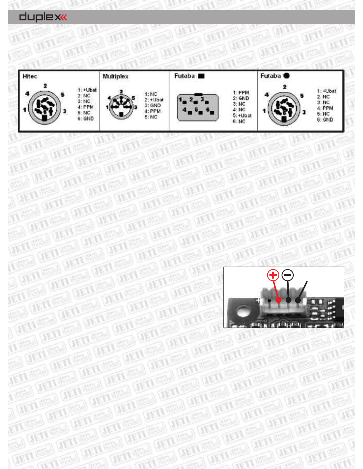
the corresponding pins GND, supply +Ubat and the PPM signal between the transmitter and the IN connector of the
module. Mechanically you may fix the module and the connector either to the transmitter case or the transmitter
tray.
Internal Installation:
Switch off the transmitter and place it on a soft pad in order to prevent mechanical damage. Remove the cover and
before proceeding remove batteries. Select an appropriate location in your transmitter for assembly, keeping
placement of the antenna connector in mind. Mechanical fixing of the module you may acomplish by means of
double sided tape, Velcro fastener or by small screws through holes provided in the module.
For installation of the antenna connector you may usually take advantage of one of the holes provided for additional
switches, the hole for the existing antenna 35/40 MHz, or you may drill a 6,5 mm dia. hole at an appropriate location.
In any case, the part of the connector protruding through the transmitter wall should be long enough (after screwing
the antenna in there must remain at least a small gap between transmitter case and antenna.
On the DUPLEX TU2 module there is a 4-pin connector which connects
the voltage supply and the PPM signal of the transmitter encoder to the
module (see Fig.).
Installation of theTU2 module:
1. Installation of one transmitter module Duplex 2,4GHz.
As far as transmitters of the Graupner MC line are concerned disconnect and remove the FM module and connect the
TU2 module directly to the transmitter encoder by means of the original cable. Some Graupner MC transmitters as
well as other transmitter types are not equipped with standard connectors. In that case you will have to apply the
cable which is contained in Duplex TU2 package or use a special cable as provided in the assembly kit of your actual
transmitter.
2. Installation of two transmitter modules Duplex 2,4GHz with the aid of the assembly kit SWTU-2.
In order to achieve a maximum increase of remote control system reliability you may take advantage of two Duplex
transmitter modules in line with two receiers. For this purpose you need the cable contained in the assembly kit
SWTU-2 which fits transmitters with standard connectors (for instance the Graupner MC line). This cable is also
applicable to other transmitters but it has to be adapted to the actual transmitter configuration or omitted altogether.
PPM
EN
Transmitter modules
Page 4

Connection of the external buzzer and earphones:
An earphone or an additional external buzzer may be connected to
the module TU2. Connection to the module TU2 is carried out by
means of the gold plated pins as shown in the picture (polarity is of no
significance). The module TU2 is able to recognize the connection of
earphones and automatically disables the buzzer for generation of
telemetric alerts. Alerts concerning loss of range, low receiver are
generated into earphones as well as into the buzzer.
Assembly kit: Voice-1
1. Jack 3,5mm -
2. Ext. buzzer - accessory
Earphone connecting accessory
1
2
SWTU2
JETIBOX
Earphones Buzzer
PPM
EN
Installation of the DUPLEX TA Module
The DUPLEX TA module is designated for installation into the Aurora 9 transmitter. The TA module is delivered without
antenna and case. For this purpose take advantage of the original antenna and case of the Hitec module which have
been delivered with the transmitter.
Assembly of the DUPLEX TA Module :
During installation of the module be sure that the transmitter is switched off!
1. From the back of the transmitter carefully remove the original transmitter module and simultaneously loosen by
slightly turning the transmitter antenna, which is connected by a cable to the transmitter module. Instructions for the
removal of the antenna and module you may find in the manual of the appropriate transmitter module.
2. Disassemble the original transmitter module case, held together by sidewise positioned screws, by unscrewing
and removing these screws.
Transmitter modules
Page 5
EN
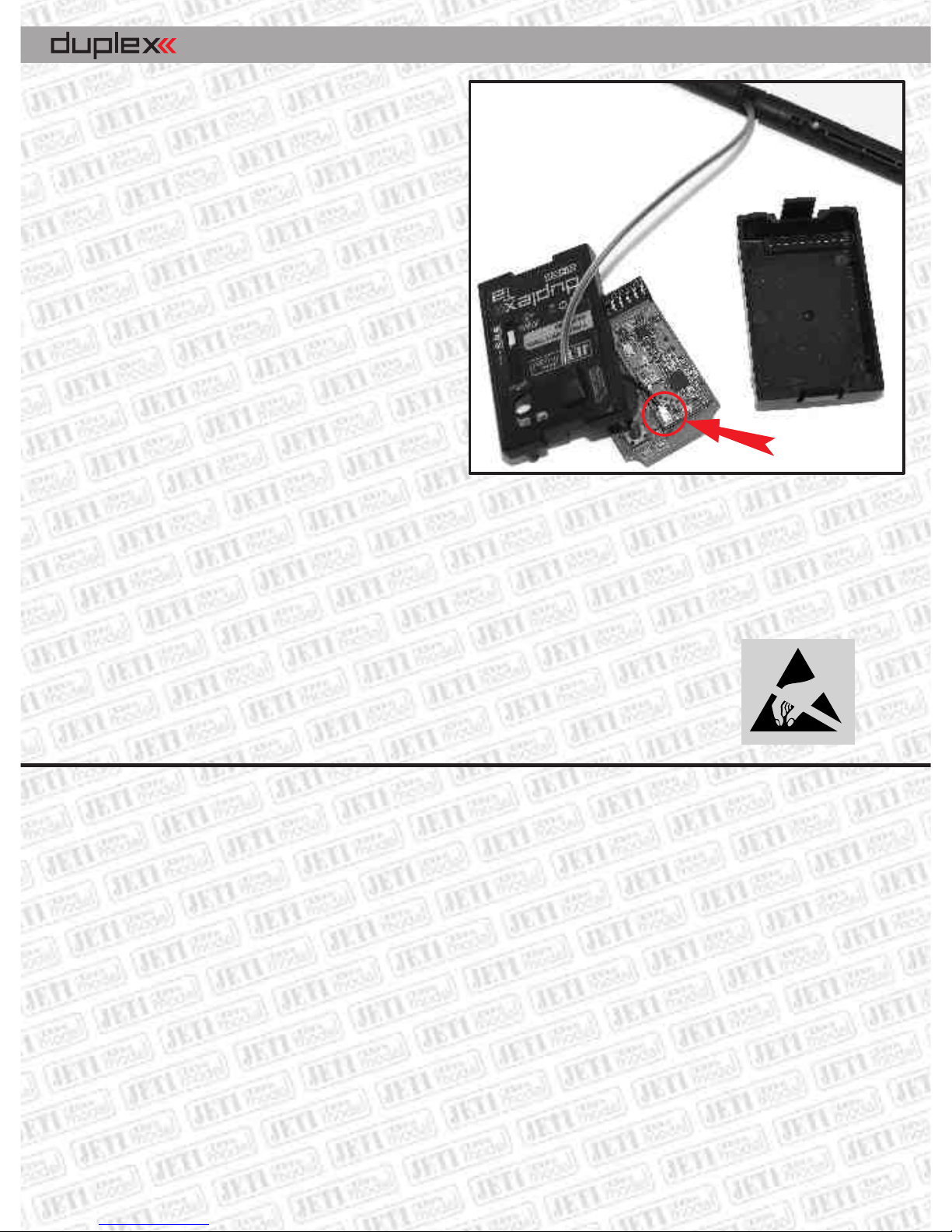
3. After removal of the case disconnect the antenna
cable from the connector of the original module
4. Open up the hole for the originally used push
button in the case to 6 mm dia.
5. Connect the antenna cable to the TA transmitter
module connector and put everything back into the
case.
6. Close the case again by means of the two screws,
shift the antenna in place and plug-in the module back
into the transmitter.
7. Place a new sticker DUPLEX EX, as delivered with
the TA module, over the original module sticker.
Now the module must be paired with the receiver, see
ELECTROSTATIC SENSITIVE DEVICE
OBSERVE HANDLING PRECAUTIONS
Putting into operation
Pairing with the receiver and performance verification
Any receiver and transmitter module takes advantage of digital transfer for communication purposes, in order to
enable direct address communication between the equipment it is necessary to apply the so called pairing between
them. The description of a transmitter module is given by its unique address which after pairing to the receiver
ensures, that the receiver will accept only data from this definite transmitter. There may be paired as many receivers as
you like with the transmitter module, but a receiver can be paired to one transmitter only.
Install the receiver into your model. If the equipment is switched on first time we explicitly recommend to ensure that
no detrimental effects on health or property may occur due to unexpected receiver output conditions (for instance
badly adjusted mixers, reversed outputs etc.).
Activate receiver pairing by means of the shorting plug (BIND PLUG), which is a part of the receiver.
below. Be careful when switching on the transmitter Aurora 9, the module is not switched on as long as the
transmitter is not in transmitting mode. You will recognize the switch-on state of the module when the red LED starts
blinking. The blinking red LED on the module indicates communication between module and transmitter. At the
transmitter working in Duplex mode moreover a green LED will turn on.
Disassembled module Aurora
UFL connector
Transmitter modules
Page 6

Plug-in the shorting plug into the connector "Ext." and switch on the receiver. Then switch on the
transmitter. If pairing was successful the transmitter will confirm this by a short beep (by a lower and then a higher
tone). If no confirmation of a successful pairing occurs, try to repeat the whole procedure or try to verify via the
JETIBOX whether the receiver is in „Normal Mode“ (a receiver in „Clone Mode“ is not allowed to transmit and hence
cannot confirm pairing). After pairing confirmation remove the BIND PLUG from the receiver connector.
Verify correct reactions of the model to transmitter commands (servo deflections have to follow corresponding stick
deflections). If not, check whether servos are plugged into correct positions and the receiver is correctly adjusted
(adjustment of mixers etc.). DUPLEX receivers can be reset to original state by the JETIBOX (connected to the receiver)
with the help of the menu Autoset-normal.
DUPLEX Tx modules are adapted to cooperate with transmitters working with PPM signals. If the transmitter is
switched to PCM mode or the installation has not been performed properly, the transmitter module will emit a
repeated allert tone (3x long beep).
Range test
Before initial utilization of the transmitter (or receiver) it is advisable to make a range test and thus verify correct
functions of the transmitter and receiver HF circuits. The transmitter can be switched to the test mode by the JETIBOX
or by the BIND PLUG.
After connection of the JETIBOX to the transmitter select the item "Range Test" and push the button U (upward
arrow). The transmitter will be switched to range test mode and the transmitted power will be decreased to less than
10%. This situation is reported acoustically by interrupted beeps (short and long tone). After pushing the button U
again (upward arrow) the transmitter returns to normal state, the output power increases to the normal value and
beeping ceases. Test mode activation by means of the BIND PLUG commences analogical to receiver pairing as shown
above. However, after the pairing procedure keep the shorting plug plugged in the receiver. As long as the shorting
plug remains plugged in, the transmitter will stay in range test mode. In this mode the transmitter behaves in the
same way as if range test would have been activated by the JETIBOX. In order to stop this mode remove the shorting
plug from the receiver.
Place the model and transmitter at least 80 cm high above ground. A correctly working transmitter and receiver in test
mode should have a range of at least 50 m. If not, first of all verify correct antenna installation (transmitter and
receiver). If the test still shows no success, do not use the equipment and contact your dealer or a service center.
Automatic Test
The TX module comprises an automatic test system as well. After switching on the receiver and transmitter a quality
evaluation of the transmission path including all antennas is being performed. The result is reported 1 second after
switching on of the transmitter by an acoustic signal of the TX module. No signal at all after lapse of this period
signifies a flawless transmision path. An impaired transmission quality is indicated by one to four tones of the TX
module. One single tone can already occur if the model is slightly further away of the transmitter, but the transmission
path is OK. If more tones are released check the TX antenna connection as well as positions of the RX
antennas and make a range check.
EN
Transmitter modules
Page 7

Connection of the JETIBOX
As already mentioned the JETIBOX terminal can be connected to DUPLEX Tx transmitters. With the help of this
terminal transmitter data and parameters as well as currently connected equipment (receivers, telemetric senzors
etc.) may be displayed and adjusted.
DUPLEX transmitter modules are equipped with a three pin connector (see marking) intended for connection of the
JETIBOX. Connection can be easily done by the interconnection cable delivered with the JETIBOX. When connecting
pay attention to correct orientation of the connectors. We recommend to connect or disconnect the JETIBOX only, if
the transmitter is switched off. When the transmitter has been switched on you will be able to skim through items of
the transmitter or other connected equipment with the help of the JETIBOX push buttons.
Parameter Adjustment with Help of the JETIBOX
When connecting the JETIBOX terminal to the transmitter you may select whether you want to display and adjust
transmitter parameters (Tx), connected receivers (Rx) or other equipment (Mx) which is able to communicate with
the JETIBOX. Communication with Rx and Mx is only possible if the transmitter module and receiver are paired and if
there exists a radio link. This situation is shown in the LCD display by a downward showing arrow beside the Mx and Rx
text.
After adjustment of the claimed item (Tx/Rx/Mx) push the button D (downward arrow). Afterwards you may skim
with help of pushbuttons through the menu of the selected equipment. When working with equipment Rx or Mx you
may get back to the transmitter module menu Tx by holding down button U (arrow upward) for a time longer than 2
seconds.
When scrolling positions Tx/Rx/Mx with the button R (arrow right) basic telemetric data can be shown. In the first line
of the JETIBOX display you will see the RX antenna voltage as well as the receiver supply voltage. The second line
shows values of the telemetry senzor, which is connected to the receiver input Ext. These Data are copied from the
second line of the actual data display of the connected senzor or from the Expander. If there is no gadget connected to
the receiver input Ext., the second line of this menu position will show now data.
Summary of Transmitter Items:
The introductory display shows the transmitter type. By pushing button R (right arrow) the identification numbers of the
transmitter module and of the actual paired receiver are displayed.
FW ver. 3.00 – Firmware-Version of the transmitter module. New versions are available on the internet pages of
www.jetimodel.com .
Diag – shows more detailed informations about the transmitter and paired receiver condition.
Identification of the active receiver antenna (A1/A2) and of the actual signal intensity rated from 0 to 9 (best).
On the right side according to condition the following indicators may be shown:
R - Range Test mode (range test)
EN
Transmitter modules
Page 8

P - after switching on the transmitter has not yet been paired (did for the moment not
yet find a paired receiver)
S - there are no receiver data available (bad signal)
T - low voltage of the transmitter battery
B - low voltage of the receiver battery
I - there are no PPM pulses from the transmitter accessible (installation error, PCM
mode etc.)
Most of the conditions shown are accompanied by acoustic signals.
By pushing button U (upward arrow) range test mode may be activated.
ImpDiag – shows the actual number of transmitter PPM channels (K2 till K16, depends on transmitter type).
Volt MIN/ACT/MAX - minimum, actual and maximum value of transmitter module supply voltage. Reset („zeroing“)
of the min. and max. values is always executed when the transmitter is switched on and after location of the paired
receiver. Alternatively the displayed values may be reset by simultaneously pushing buttons L and R (left and right
arrow).
Rx Signal Level – shows the actual signal intensities of individual RX antennas. The intensity is shown in steps from 0
till 9 and the highest rating of 9 indicates the best reception of a particular antenna. A dash (-) indicates that the TX
module is not receiving any informations about the reception quality of the particular antenna. Either the receiver is
not connected or backward transmission from the receiver to the transmitter is at the range limit.
Volt ACT/ALARM – shows the actual value of transmitter module supply voltage and the adjusted limit for an alert
signal "T" (see menu Diag). By buttons L and R (JETIBOX buttons -left or right) the alert start limit may be adjusted.
Alarm Level – setting of the level, at which the transmitter module will start signalling low reception level of
receiver antennas. The lower line shows the actual level of the individual receiver antennas. If the reception with the
better signal level will fall below the set level, an acoustic sound will point out to this fact (2x short high-pitched
tones). See: RX Signal Level.
Input Mode – setting of the type of transmitter PPM input pulses. Most transmitters are using standard PPM signals.
You should choose PPM v2 or v3 only, if your transmitters allows switching to a different PPM mode. In most cases this
is related to transmitters with the ability of trasmitting more than 8 channels in PPM mode, as for instance 12 channel
Transmitters.
Alarm Error PPM – permission / prohibition of acoustic signalling of an unconnected or erroneous transmitter PPM
signal. Switching-off this type of signals is only recommended, if the module is used for telemetric purposes only and
is not connected to a transmitter used for model control.
EN
Transmitter modules
Page 9

Mx Tone 1 - enables adjustment of warning tone frequency (Hz), which reveals alert conditions of the connected
equipment Mx (usually a telemetric senzor). A value of 0 indicates that the warning tone is switched off.
Mx Tone 2 - enables adjustment of information tone frequency (Hz), which informs about the alert condition of the
connected equipment Mx. This tone has Morse alphabet character and follows immediately after the warning tone. A
value of 0 indicates that the information tone is switched off.
Acoustical Condition Signalling
All types of transmitter modules are equipped with an acoustic output which is utilized for signalling of different
transmitter, receiver or attached telemetric senzor conditions. The following conditions are reported by acoustic
signals:
I ( _ _ _ ) 3x long low tone
PPM pulses of the transmitter are not accessible (installation error, PCM mode etc.)
P ( . -) short low tone and consecutive high tone -
a paired receiver has been found
B ( - ) long high beep
low receiver battery supply voltage
T ( * ) short high beep
low transmitter battery supply voltage
S ( * * ) 2x short high beep
there are no receiver data available (bad signal)
R ( . - . - ) alternating short and long tones
Range Test mode (range test)
M alert indication from attached telemetric senzor
first beep (revelation tone) corresponding to adjusted value Mx Tone 1
consecutively a Morse alphabet beep (information tone due to adjustment
Mx Tone 2)
Alert indication by Morse alphabet signal, character of signal is given by the type and adjustment of attached
equipment (receiver, telemetric senzor etc.).
For Tx modules we grant a warranty of 24 months from the day of purchase under the assumption that
they have been operated in conformity with these instructions at recommended voltages and that they
were not damaged mechanically. Warranty and post warranty service is provided by the manufacturer.
We wish you sucessful flying with the products of : JETI model s.r.o. Pribor, www.jetimodel.com
RF Output Power - - allows setting an output power of Tx module. (Maximal output power can differ in
different countries, according to local rules)
- transmitting in 2.4 GHz band with max. power 10mW
- transmitting in 2.4 GHz band with max. power 100mW (recommended setting)
- transmitting in 2.4 GHz band operates in combination of 10mW and 100mW max.
power
EN
Transmitter modules
Page 10
Tab. 2 - Assignment of Modules and Transmitters / Senderzuordnung zu den einzelnen Modultypen
Transmitter / Module
TU2
TF
TG2
TGi2
TGi
TGs
TMe
Tmp
TA
Futaba: 7U, 8U, 8J, 9C,9Z, FN, T10C, 3PK, 3PJ, F-16, FC-18+, FC-28
•
•
–
–
–
–
–
–
Futaba: FC-16, FC-18 JUNIOR, T6EXHP, T6EXA, 12FG, 12Z, FX-14, FX-18, FX-30,
FX-40, F-14
•
–
–
–
–
–
–
–
Hitec: Optic 6, Eclipse 7, Prism 7, Aggressor CRX/SRX
•
•
–
–
–
–
–
–
Hitec: Laser 4, Laser 6, Flash 5, Optic 6 sport
•
–––
–
–
–
–
Graupner/JR: X-347, X-388, X-9303, MX-22, X-3810 ADT, PCM-10S, PCM-10X
•
–•–
–
–
–
–
Graupner/JR: FM-6014, MC-17, MC-18, MC-20, MC-24
•
–
–
•
–
–
–
–
Graupner: MC-10, MC-12, MC-14, MC-15, MC-16, MC-19, MC-22, MC-16/20,
MX-12, MX-16s
•
–––
–
–
–
–
Graupner/JR: MX-24s
•
–
–
–
•
–
–
–
Multiplex: EVO 7,9,12
•
–––
–
•
–
–
Multiplex: Profi 3000, 4000
•
–––
–
–
•
–
Multiplex: Cockpit SX
•
–––
–
–
–
–
Hitec: Aurora 9
–
–––
–
–
–
•
Other Transmitters / Andere Sender
•
–––
–
–
–
–
Page 11

alarm tone 2
step 100Hz
minimal voltage
actual voltage
maximal voltage
alarm tone 1
step 100Hz
- no signal
0 bad signal
9 the best signal
antena activity state
reduced Tx power indicator
no. of Tx channels
actual voltage
alarm voltage
10mW (Reduced)
10/100mW (Fr)
100mW (max.)
Testing beeper
on each alarm
Button down
starts test
Rx Mx
Rx: 0000 0000
Tx: 0000 0000
Alarm Level
Ant1: 9 Ant2: 9
0 to 9
Input Mode
PPM standart
PPM standard
PPM v2 (2x)
PPM v3 (1.3)
Alarm Error PPM
On
ON
OFF
The menu structure of the transmitter module by the JETIBOX Diagram
Volt Min/ACT/MAX
10.0/10.0/11.5
Rx signal Level
Ant1: 9 Ant2: 9
Sound test
Rx Found
MeasureOrSetting
Main Setting
Volt ACT/ALARM
10.0V / 8.5V
Mx Tone1
3900 Hz
Mx Tone2
2000 Hz
RF Output Power
100mW (max.)
Diag A2 PS
RangeTest B
Transmitter Type
Duplex Tx
MeasureOrSetting
Measure
Duplex TX
EX FW ver. 3.00
ImpDiag
K7
Tx
Rx: Ant=9/9 5.0V
43.2A 21.4V
Page 12

Duplex Transmitter modules
Receivers
EN
Series DUPLEX EX receivers are designated to operate with series DUPLEX and DUPLEX EX transmitter modules in
the 2.4GHz band. Thanks to the full digital and bidirectional communication between transmitter and receiver they
offer new chances in the field of remote controlled models.
The DUPLEX EX transmitter modules and receivers take advantage of modern hightech technologies and offer thanks
to precize production and test methods maximum safety and reliability.
The DUPLEX EX is the successor of the recent DUPLEX system, but it comprises full compatibility with it. On the other
hand the series EX extends its capabilities especially in the field of telemetric data transfer and offers thus an even
better insight into the state of the model. Full utilization of the new properties is supported by the JETIBOX PROFI
terminal, which offers improved imaging posibilities and user comfort. In connection with the program package
FlightMonitor it facilitates parameter setups of particular system components, enables data processing and
monitoring of telemetric data during flight and delivers tools for exact after flight analyzis of data collected during
flight. This way it implements a new dimension into the management and utilization of the whole system.
An additional satellite receiver RSat complements the receivers R9, R10, R11, R12, R14 and R18. This receiver is a
full DUPLEX system receiver offering the complete functional spectrum of the system. Instead of classical servo pulses
the output of the RSat receiver offers a PPM signal only. This PPM signal is furtheron processed by the receivers R9,
R10, R11, R12, R14, R18 or by compatible RC equipment which requires a PPM signal at the input.
Current Supply:
The receiver current supply can be realized either by application of NiCd batteries, by stabilized voltage supplies
provided by controllers (electric flight) or by Li-xx cells via stabilizers like the MAX BEC. But it is of utmost importance
to keep always the allowed supply voltage range of the receiver and servos in mind. If all servo connectors are
engaged by servos an Y-cable can be used for current supply. The supply batteries of the BEC or the Y-cable can be
connected to any arbitrary receiver output, but do by no means use the output marked Ext. for receiver current supply
purposes.
The receivers EPC R11, R12, R14 and R18 are equipped with a separate MPX supply connector. We recommend to use
this connector for the receiver current supply and servos because of its high current load capability and reliability.
Operation:
Operation of the DUPLEX system is very similar to a FM system. We recommend switching on the transmitter first and
thereafter the receiver. The transmitter confirms the on state of the receiver by a short beep. When switching off the
system we recommend to switch off the receiver first and after that the transmitter.
Page 13

Installation:
Wrap the receiver with soft foam and position it as far as possible away of interference sources (servos, electric
motors). Place the active ends of the antennas with an angle of 90° inbetween and as far away as possible of each
other. The minimum bending radii of the antenna cables should not be smaller than 1 cm. The active parts of the
antenna must remain straight and should be kept as far off as possible of metal parts. If the model fuselage consists of
carbon fibre the active antenna parts should protrude through the fuselage wall to the outside.
Pairing:
Before using a new receiver or transmitter they must be first of all bilaterally paired. The information flow between
receiver and transmitter occurs on a full digital basis, therefore the equipment which is mutually communicating in a
common frequency band must be equipped with an address. Pairing (addressing of the equipment) is realized by
plugging in of the so called BIND PLUG into the connector for external equipment marked Ext. and by switching on the
receiver. After that the transmitter is switched on and confirms pairing with the receiver by a double beep. Remove the
bind plug from the receiver. The transmitter draws attention to the presence of a bind plug in the receiver by acoustic
signals.
It is also possible to perform pairing without BIND PLUG with aid of the JETIBOX. In that case the JETIBOX must be
connected directly to the receiver. Select at the JETIBOX the position (pairing) and push the key U (arrow up). The
receiver is waiting now for switching on of the transmitter with which pairing shall be carried out. The transmitter
reports pairing by a double beep and everything is ready for operation. Should pairing be unsuccessful, switch off
transmitter and receiver and repeat the whole procedure as described above.
It is possible to pair an arbitrary number of receivers to one transmitter. The receiver itself can be paired to one
transmitter only, that means that the receiver is paired to that transmitter to which it has been paired eventually.
Telemetric Data Transfer in Real Time:
Any receiver allows transfer of the actual on board system voltage, that means of the receiver voltage without
telemetric sensors.
It is possible to connect a telemetric sensor directly to the receiver connector marked (Ext.). If you wish to use several
sensors you may take advantage of the expander DUPLEX Ex which must in that case be connected to the receiver
connector (Ext.).
Alerting in Case of Bidirectional Signal Loss:
In case of loss of bidirectionel communication between transmitter and receiver the transmitter DUPLEX module
reports this event by acoustic signals. This situation means that at the given instant there are no data available of
telemetric sensors or equipment connected to the receiver input (Ext.). But the model can in this situation still be
controlled.
Description of JETIBOX you will find in page number 25.
We wish you sucessful flying with the products of: JETI model s.r.o. Pribor, www.jetimodel.com
EN
Receivers
Page 14

Table 1. - DUPLEX Rx ReceiversR4-R8:
Basic Data
R4
R4C
(R4Cmini)
R5
(R5
indoor)
R6
(R6 EPC*)
R6F indoor
R6G indoor
R7
(R7
indoor)
R8
(R8 EPC*)
Dimensions [mm]
35x 20x7
30x23x13
44x20x7
45x24x12
38x20x6
44x20x7
50x30x12
Weight [g]
4,8
8 (7)
5,2 (4,8)
11 (14)
3
5,5
15 (18)
Antenna Length [mm]
2x100
1x200
(internal)
2x100 (2x45)
2x100
30
2x100 (2x45)
2x200
# of Channel Outputs
4
4
566
7
8
Temperature Range °C[ ]
-10 to +85
-10 to +85
-10 to +85
-10 to +85
-10 to +85
-10 to +85
-10 to +85
Supply Voltage V [ ]
3.2 – 8.4
3.2 – 8.4
3.2 – 8.4
3.2 – 8.4
3.2 – 8.4
3.2 – 8.4
3.2 – 8.4
Average Current mA [ ]
40
40
40
45
404045
Real Time Transmission of Telemetric Data
YES
YES
YES
YES
YES
YES
YES
Programming
JETIBOX
JETIBOX
JETIBOX
JETIBOX
JETIBOX
JETIBOX
JETIBOX
Support Satellite Receiver Rsat
NO
NO
NO
NO
NO
NO
NO
Power Output dBm[ ]
6
6
6
20
6
6
20
Receiver Sensitivity dBm[ ]
-98
-98
-98
-100
-98
-98
-106
* xternal ower onnector E P C
Page 15

Table 1. - DUPLEX Rx Receivers: R9-R18
* xternal ower onnector E P C
Basic Data
R9
R10
R11 EPC*
R12 EPC*
R14*
R18*
Rsat2
(RMK2)
Dimensions [mm]
51x24x11
50x28x13
51x24x11
50x28x13
62x38x16
62x38x16
35x23x6
Weight [g]
13
17
15
22
30
30
12
Antenna Length [mm]
2x200
2x200
2x200
2x400
2x400
2x400
2x200
(2x75, 2x150)
# of Channel Outputs
9
10
11
12
14
18
PPM 4/16
Temperature Range °C[ ]
-10 to +85
-10 to +85
-10 to +85
-10 to +85
-10 to+85
-10 to +85
-10 to +85
Supply Voltage V [ ]
3.2 – 8.4
3.2 – 8.4
3.2 – 8.4
3.2 – 8.4
3.2 – 8.4
3.2 – 8.4
3.2 – 8.4
Average Current mA [ ]
30
30
30
30
40
40
30
Real Time Transmission of Telemetric Data
YES
YES
YES
YES
YES
YES
YES
Programming
JETIBOX
JETIBOX
JETIBOX
JETIBOX
JETIBOX
JETIBOX
JETIBOX
Support Satellite Receiver Rsat
YES
YES
YES
YES
YES
YES 1x Rsat2
contained in package
-
Power Output dBm[ ]
202020
20
20
20
20
Receiver Sensitivity dBm[ ]
-106
-106
-106
-106
-106
-106
-106
Page 16

Communication with the DUPLEX Receiver with aid of the JETIBOX
The JETIBOX can be connected to the receiver in two ways:
1. By direct connection JETIBOX <-> receiver
Plug the connector of the interconnecting cable (enclosed in the JETIBOX package) into the receptacle marked Impuls
+ - (positioned at the right side of the JETIBOX) and the other end into the receiver receptacle marked Ext. Connect the
current supply to the receiver (see current supply) or to the current supply receptacle of the JETIBOX.
2. By wireles connection JETIBOX <-> transmitter <-> receiver
In that case the JETIBOX must be connected to the transmitter. Switch on the transmitter and connect the current
supply of the receiver.
The display shows the text Tx and arrows to the right and down. You may enter the receiver menu by pushing the key R
(arrow right), the display shows the text Rx after that you enter the receiver menu by pushing key D (arrow down). The
display picture corresponds to the picture as shown in case of direct connection (see item 1).
Wireless connection with the receiver is possible in Normal mode only. If you would during wireless connection
change from Normal mode to Clone mode, the receiver would switch to monitoring mode and the JETIBOX would stop
to respond. In order to renew communication with the receiver the JETIBOX will have to be reconnected to the receiver
directly, see item 1. In case of using a receiver which has before been working in monitoring mode (Clone) in an other
model, do not forget to set it back to the original mode (Normal).
The JETIBOX can be disconnected only after the receiver has been also disconnected from its voltage supply. It is
anytime possible to follow up the condition of the receiver or to set up its parameters even during its operation in the
model, but this ought to be done very carefully. Setups should be carried out only if security of the model against
damage and of persons against injury is warranted. As an important safety measure an accidental motor start should
be prohibited by all means, removing the propeller from the model might be very helpful!
Communication with the Expander DUPLEX Ex by taking advantage of the JETIBOX (JB):
Plug the connector of the interconnecting cable (enclosed in the JETIBOX package) into the receptacle marked (Rx) at
the back of the expander and the other end into the receptacle of the receiver marked (Ext.). Connect the JETIBOX to
the transmitter module. Switch on the transmitter and connect the current supply to the receiver (see current supply).
In the JETIBOX display there appears the text Tx and by pushing key R (arrow right) twice you will select the item Mx.
By pushing key D (arrow down) will enter expander menu. The main menu (selection of the connected device Tx, Rx,
Mx) will be attained by holding down key U (arrow up) for a longer time).
Overview of Receiver Data Items
The introductory display shows the type of receiver. By pushing of key R (arrow down) more detailed data of receiver
and transmitter can be cued.
Pairing: by pushing the key U (arrow up) pairing of the receiver with the transmitter will be executed. Pairing of the
receiver should only be carried out when the JETIBOX is directly connected to the receiver.
EN
Receivers
Page 17

RX/TX: Item RX shows the unic production number of the receiver. Item TX shows the unic production number of the
transmitter, to which the receiver has eventually been paired.
Rx Diag: Item A1 or A2 shows which antenna the receiver is using at present. Item Kx informs about the number of
transferred channels (this number depends of the transmitter abilities).
By means of key D (arrow down) you arrive at the line of basic mode selections, where you may select read out of
measured values (Measure) or setup of the receiver (Main setting, Channel set, Out Pin Set, Auto Set).
Measure: enables read out of measured data of the maximum, minimum and actual receiver voltage.
-Volt Min / Act / Max : the receiver is checking the supply voltage and indicates limit values and extremes which
occurred during operation; at the same time it also shows the actual receiver voltage. Without switching on the paired
transmitter the values MAX and MIN will not change, only the value of the actual voltage ACT will be updated. In order
to delete values MAX and MIN, keys L (arrow left) and R (arrow right) must be pressed simultaneously.
Main setting: Basic setup, here you may adjust general properties of the receiver which are common to all output
channels.
- Signal Fault Delay: specifies the deadline after which the receiver outputs change due to signal loss to
preadjusted positions of the particular outputs or after which they become switched off (due to setup of Signal Fault
in the menu Out Pin Set).
- Volt act/alarm: the first item shows the actual receiver supply voltage, the second value serves for the setup of
the alert decision threshold. As soon as during operation the actual voltage decreases below the set threshold, the
transmitter will announce this situation by an acoustic tone.
- Output Period: setup of the output signal period (standard setup 20ms), analog servos respond faster with lower
values (shorter response time) and consume more current. If the value is set too low some servos may chatter. The
output period may also be synchronized with the transmitter - Output Period - By Transmitter.
-RX mode: this setup switches the receiver to monitoring mode (Clone). This mode should only be used in
applications with two or more receivers, working simultaneously in a model in connection with a single transmitter
module. One receiver should work as master receiver (Normal) and the others in monitoring mode (Clone). The mode
change (Normal / Clone) must be carried out only with the JETIBOX connected directly to the receiver.Telemetric
sensors can be operated with a receiver in Normal mode only.
-PPM Output mode (applicable to RSat receivers only) Setup of the satellite receiver mode
-Computed: the signals received from the transmitter can be processed furtheron in the receiver
and its menus Channel setand Out Pin Set(mixers, programmable channel outputs a.s.o.)
-Direct: signals received from the transmitter are notfurtheron processed in the receiver, they are
generated without any change at the output of the sallite receiver in form of PPM signals
-Number of PPM Output Pulses: (valid for RSat and RMK) Setup of PPM pulse number at the Rsat receiver. If there
are transmitted less channels than the set number of PPM pulses at the receiver, then the remaining pulses will be
replaced by one pulse with a length corresponding to the pulse length adjusted in the FailSafe menu of the given
channel. In the reverse case the number of output pulses will be reduced to the default setting number.
EN
Receivers
Page 18

-Signal fault:
- Individual set: the behaviour of the output in case of a signal loss will be conducted by the setup of particulat
channels in the menu Measurement/Setup – Setup of the output, where the behaviour of particular output channels
in case of signal loss may be set – to repeating of the last deviation or to FailSafe.
- Output switching off: in case of signal loss, after the elapse of the set time in the menu FailSafe Retard there
will exist no more PPM pulse generation at the receiver output.
- Menu display: allows menu setup in full or reduced shape. In the reduced menu display are for the sake of setup
simplification some of the selected items not shown. But all receiver setups are taken into account, even the given
item is not shown in the reduced menu.
Channel set: parameter setup of (received) individual input channels CH
-Set Input Channel: selection of the input channel which has to be set up, value A represents the actual throw of
the selected input channel.
-Set Center: neutral position setup of the input channel, this parameter is important for further processing of
mixers, reverse, gain etc.
-Mix CHa and CHb: makes mixing of the selected channel with another channel feasible.
-Mix Relation: setup of the mixing ratio, the mixed channel always features a ratio of
50 %. For instance, mixing of CHa and CHb with a ratio of 100% = 50% CHa and 50% CHb, a ratio of 50% = 50% CHa
and 25% CHb, a ratio of 200% = 50% CHa and 100% CHb.
-Mix Sign: the first sign of the mixed channel specifies whether the channels are subtracted or added
Out Pin Set: Relation of functions to individual output channels (pins) Y of the receiver.
-Set Output Pin: Selection of the output channel whose setup you want to show or change.
It is possible to add to a R10, R12, R14, R18 Duplex receiver two satellite receivers or further R10, R12, R14, R18
receivers. In case of the Duplex R18 (R12) receiver it is possible to switch output Y17 (Y12) to the function Sat2 and
output Y18 to Sat1. The output channel marked Sat 2 may be set to receiving mode or to generation of PPM signals.
This function is of use in case of a bidirectional connection of several receivers or satellite receivers. The output channel
marked Sat 1 can be set to PPM signal mode only.
-Set mode SAT: on the Duplex receivers R9,R10, R11EPC, R12EPC, R14, R18 the outputs SAT1 and SAT2 can be
affiliated with following functions
- PPM Off: the particular output is neither generating nor receiving a PPM signal
- PPM Input: the particular input is expecting a PPM signal of the connected receiver
- PPM Output: the receiver will generate PPM signals on output SAT2
-Set mode SAT: on the Duplex receivers R11, R12, R18 the outputs SAT1 and SAT2 can be affiliated with following
functions
- CH xx: the PPM signal on the particular output will neither be generated nor received. The output has the same
function like the outputs Y1-Y16.
- PPM Input: the particular input is expecting a PPM signal of the connected receiver
- PPM Output: the receiver will generate PPM signals on the output SAT2
(valid for RSat and RMK) behaviour setup of the satellite receiver in case of signal loss.
EN
Receivers
Page 19

- PPM Alarm Code:
reports absence of the connected signal. By means of loading a morsealphabet character tones are set, which
acoustically announce the absence of the PPM signal at the particular receiver input. These acoustic signals are
generated by the transmitter module.
-Set Input Channel: function affiliation to particular outputs, any input channel or its mixing product which
may be specified in the menu Channel Set can be set up.
-Reverse A: makes throw reverse at the output in the half plane A possible, the half planes are subdivided
according to the neutral position setup (Channel set - Set Center)
-Reverse B: makes throw reverse at the output in the half plane B possible
-Gain A: Amplification of the output throw in half plane A (100% - without changes)
-Gain B: Amplification of the output throw in half plane B (100% - without changes)
-Signal Fault: setup of the receiver behaviour in case of signal loss, repeat- repetition of the last valid throw
positions, out off – output switched off, FailSafe – transition to preset throw positions of individual outputs which
may be set up in the FailSafe menu.
-FailSafe: throw setup of a selected output in case of signal loss
-Delay: delay of servo speed (at the output) in case of a change at the input, the entry time corresponds with
the transit time within the output range between 1ms to 2ms which, for instance, may be suitable for
retracting a landing gear
-Curve: Setup of a channel output curve
-ATV High Limit: restriction (reduction) of the maximum throw of a particular output (half plane B)
-ATV Low Limit: restriction (reduction) of the maximum throw of a particular output (half plane A)
-Output Group: setup of a particular output for a selected group of output pulses, which are generated by the
receiver at the same time . See page 56.
Auto Set: complete receiver preset for predefined functions. After selection of the desired function the receiver
setup is executed by simultaneous pressing of the left and right JETIBOX keys for about 3 seconds.
-Normal: basic setup, mixers switched off, individual input channels are affiliated to corresponding outputs, i. e.
input CH1 is affiliated to output Y1 etc.
-MixCH1&CH2 Elevon: affiliates the mix of the received CH1 and CH2 to the output channels Y1 and Y2
-MixCH2&CH4 V-Tail: affiliates the mix of the received CH2 and CH4 to the output channels Y2 and Y4
if one of the outputs SAT1/2 is set to PPM input mode, an acoustic signal can be set up which
EN
Receivers
Receiver
R9
R10
R11EPC
R12EPC
R14
R18
SAT 1
PPM IN
•••••
•
PPM OUT
–––––
–
OUT Yx
–
–
Y11
–
–
Y18
SAT 2
PPM IN
–•–••
•
PPM OUT
–•–••
•
OUT Yx
–––
Y12–Y17
Page 20

Channel Set
SetInputChannel CHx
Set Center
Mix CHx and CHy
Mix Relation
Mix Sign
CH1
1,5ms
CH1 and CH1
100%
+
CH2
1,5ms
CH2 and CH2
100%+CH3
1,5ms
CH3 and CH3
100%+CH4
1,5ms
CH4 and CH4
100%
+
CH5
1,5ms
CH5 and CH5
100%
+
CH6
1,5ms
CH5 and CH6
100%
+
CH7
1,5ms
CH7 and CH7
100%+CH8
1,5ms
CH8 and CH8
100%
+
EN
Receivers
Out Pin Set
Set
Output
Pin
Set
In
Channel
Reverse
A
Reverse
B
Gain A
Gain B
Signal
Fault
Fail
Safe
Delay
Curve
ATV
High
Limit
ATV
Low
Limit
Output
trim
Output
group
Y1-Y18
CH1-CHx
off
off
100%
100%
Fail save
1,5ms
0s
linear
2,0ms
1,0ms
0,0ms
A
Samples of receiver setup:
(changes against default values are marked bold in the tables)
1. V-tail: models with combined tail planes, each plane is controlled by one servo on channels Y2 and Y4, mix
combines moves of rudder CH4 and elevator CH2. Motor on CH3. In case of reverse sense of the mix change the sign
in menu Mix Sign.
Transmitter
channel
Channel Set
SetInputChannel CHx
Set Center
Mix CHx and CHy
Mix Relation
Mix Sign
Elevator
CH2
1,5ms
CH2 and CH4
100%
-
Motor
CH3
1,5ms
CH3 and CH3
100%
+
Rudder
CH4
1,5ms
CH4 and CH2
100%
+
Function
Out Pin Set
Set Output
Pin
Set In
Channel
Reverse
A
Reverse
B
Gain
A
Gain
B
Fail Safe
Delay
Curve
ATV
HighLimit
ATV
LowLimit
Servo 1
Y2
Mix CH2
off
off
100%
100%
1,5ms
0s
linear
2,0ms
1,0ms
ESC
Y3
CH3
off
off
100%
100%
1,2ms
0s
linear
2,0ms
1,0ms
Servo 2
Y4
Mix CH4
off
off
100%
100%
1,5ms
0s
linear
2,0ms
1,0ms
Auto Set – Normal = default setup, all received channels CH will be transferred without change to corresponding
outputs Y, that means the receiver behaves lik a classical non programmable receiver.
Page 21

3. Combination of rudder CH4 and front gear direction control (with deflection reduced on 60% of rudder
deflection), rudder on output Y4 and front gear turn (direction) on output Y7. Gear retraction on output Y8 (realistic
retraction with set Delay, exact servo endstops set - ATV).
Function
Out Pin Set
Set Output
Pin
Set In
Channel
Reverse
A
Reverse
B
Gain
A
GainB Fail
Safe
Delay
Curve
ATV
HighLimit
ATV
LowLimit
Rudder
Y4
CH4
off
Off
100%
100%
1,5ms
0s
linear
2,0ms
1,0ms
Gear
Y7
CH4
off
Off
60%
60%
1,5ms
0s
linear
2,0ms
1,0ms
Gear
Y8
CH8
off
Off
100%
100%
1,82ms
5,0s
linear
1,82ms
1,26ms
2. Elevon: both ailerons are controlled by independent servos on channels Y1 and Y2, move like standard ailerons on
input CH1 (one up, second down) and at the same time like elevators on input CH2 (up/down simultaneously). In case
of reverse sense of the mix change the sign in menu Mix Sign.
EN
Function
Out Pin Set
Set Output
Pin
Set In
Channel
Reverse
A
Reverse
B
Gain
A
GainB Fail
Safe
Delay
Curve
ATV
HighLimit
ATV
LowLimit
Servo 1
Y2
Mix CH2
off
off
100%
100%
1,5ms
0s
linear
2,0ms
1,0ms
Servo 2
Y1
Mix CH1
off
off
100%
100%
1,5ms
0s
linear
2,0ms
1,0ms
Transmitter
channel
Channel Set
SetInputChannel CHx
Set Center
Mix CHx and CHy
Mix Relation
Mix Sign
Elevator
CH2
1,5ms
CH2 and CH1
100%
+
Ailerons
CH1
1,5ms
CH1 and CH2
100%
-
4. Mix of ailerons Y1 and rudder Y4 (Combi - mix): rudder CH4 moves together with ailerons CH1 (mix); rudder
can be still controlled in full range. Useful for scale models.
Transmitter
channel
Channel Set
SetInputChannel CHx
Set Center
Mix CHx and CHy
Mix Relation
Mix Sign
Rudder
CH4
1,5ms
CH4 and CH1
25%
+
Ailerons
CH1
1,5ms
CH1 and CH1
100%
+
Receivers
Function
Out Pin Set
Set Output
Pin
Set In
Channel
Reverse
A
Reverse
B
Gain
A
GainB Fail
Safe
Delay
Curve
ATV
HighLimit
ATV
LowLimit
Rudder
Y4
Mix CH4
off
off
200%
200%
1,5ms
0s
linear
2,0ms
1,0ms
Ailerons
Y1
CH1
off
off
100%
100%
1,5ms
0s
linear
2,0ms
1,0ms
Page 22

Transmitter
channel
Channel Set
SetInputChannel CHx
Set Center
Mix CHx and CHy
Mix Relation
Mix Sign
Flaps
CH6
1,5ms
CH6 and CH1
100%
+
Ailerons
CH1
1,5ms
CH1 and CH6
100%
-
Function
Out Pin Set
Set Output
Pin
Set In
Channel
Reverse
A
Reverse
B
Gain
A
GainB Fail
Safe
Delay
Curve
ATV
HighLimit
ATV
LowLimit
Servo 1
Y2
Mix CH6
off
off
100%
100%
1,5ms
0s
linear
2,0ms
1,0ms
Servo 2
Y1
Mix CH1
off
off
100%
100%
1,5ms
0s
linear
2,0ms
1,0ms
6. Flaperon: mixes aileron CH1 and flaps (or airbrakes) CH6. Each aileron is controlled by independent servo
Y1 and Y2, ailerons work normally depending on stick position. At the same time, ailerons may move up
(airbrakes) or down (flaps) – depending on flap control.
7. Mix flaps-elevator: elevator CH2 automatically balances diving moment caused by move of flaps CH6. At
the same time, there is a mix flaps-ailerons (ailerons act as flaps).
Transmitter
channel
Channel Set
SetInputChannel CHx
Set Center
Mix CHx and CHy
Mix Relation
Mix Sign
Ailerons
CH1
1,5ms
CH1 and CH6
100%
-
Elevator
CH2
1,5ms
CH2 and CH6
25%
+
Flaps
CH6
1,5ms
CH6 and CH1
100%
+
Function
Out Pin Set
Set Output
Pin
Set In
Channel
Reverse
A
Reverse
B
Gain
A
GainB Fail
Safe
Delay
Curve
ATV
HighLimit
ATV
LowLimit
Elevator
Y2
Mix CH2
off
off
200%
200%
1,5ms
0s
linear
2,0ms
1,0ms
Flaps
Y6
CH6
off
off
100%
100%
1,5ms
0s
linear
2,0ms
1,0ms
5. Mix of elevator CH2 and flaps CH6: when flaps Y6 move, also elevator Y2 moves in opposite direction.
DE
Transmitter
channel
Channel Set
SetInputChannel CHx
Set Center
Mix CHx and CHy
Mix Relation
Mix Sign
Flaps
CH6
1,5ms
CH6 and CH6
100%
+
Elevator
CH2
1,5ms
CH2 and CH6
25%
-
EN
Receivers
Function
Out Pin Set
Set Output
Pin
Set In
Channel
Reverse
A
Reverse
B
Gain
A
GainB Fail
Safe
Delay
Curve
ATV
HighLimit
ATV
LowLimit
Aileron 1
Y1
Mix CH1
off
off
100%
100%
1,5ms
0s
linear
2,0ms
1,0ms
Elevator
Y2
Mix CH2
off
off
200%
200%
1,5ms
0s
linear
2,0ms
1,0ms
Aileron 2
Y6
Mix CH6
off
off
100%
100%
1,5ms
0s
linear
2,0ms
1,0ms
Page 23

8. Mix ailerons-flaps: both flaps and ailerons are on the wings. CH1 controls ailerons (Y1 and Y5), CH6 controls flaps
(Y6 and Y7). Mixes ailerons so that they work also like flaps.
Transmitter
channel
Channel Set
SetInputChannel CHx
Set Center
Mix CHx and CHy
Mix Relation
Mix Sign
Ailerons
CH1
1,5ms
CH1 and CH6
100%
+
Flaps
CH6
1,5ms
CH6 and CH1
100%
-
EN
Function
Out Pin Set
Set Output
Pin
Set In
Channel
Reverse
A
Reverse
B
Gain A
Gain B
Fail
Safe
Delay
Curve
ATV
HighLimit
ATV
LowLimit
Aileron 1
Y1
Mix CH1
off
off
100%
100%
1,5ms
0s
linear
2,0ms
1,0ms
Aileron 2
Y5
Mix CH6
off
off
100%
100%
1,5ms
0s
linear
2,0ms
1,0ms
Flap 1
Y6
CH6
off
off
100%
100%
1,5ms
0s
linear
2,0ms
1,0ms
Flap 2
Y7
CH6
on
on
100%
100%
1,5ms
0s
linear
2,0ms
1,0ms
Receivers
Out Pin Set
Set
Output
Pin
Set
In
Channel
Reverse
A
Reverse
B
Gain
A
Gain
B
Signal
Fault
Fail
Safe
Delay
Curve
ATV
High
Limit
ATV
Low
Limit
Output
trim
Output
group
Y1
Ch1
off
off
100%
100%
Fail safe
1,5ms
0s
linear
2,0ms
1,0ms
0,0ms
A
Y2
Ch1
off
off
100%
100%
Fail safe
1,5ms
0s
linear
2,0ms
1,0ms
0,0ms
A
Y3
Ch1
off
off
100%
100%
Fail safe
1,5ms
0s
linear
2,0ms
1,0ms
0,0ms
A
9) The receiver outputs will be programmed in such a manner that outputs Y1, Y2 and Y3 will be affiliated with the
same transmitter function. Servos connected to these inputs will be steering the same control device (for instance the
elevator) and will be coupled mechanically. On the transmitter is this function affiliated with the first channel CH1.
All outputs are affiliated with the input channel CH1 of the transmitter. Setups of reverse, gain, FailSafe, delay, curves
and ATV Limits check with all channels. The output channels are as well set up for the same group of servo pulse
generation. The servos will be temporally synchronized and accordingly movements of all servos will be synchronized.
Before mechanical coupling of individual servos (it is advantageous to use servos of the same type) we recommend to
bring them all with the aid of function „Output Trim“ to the same neutral position in order to prevent reciprocal loads
of the servos. The setup of equal endpoint throws can be achieved by gain changes of the individual channels with the
aid of „Gain A/B“.
Page 24

EN
Receivers
ELECTROSTATIC SENSITIVE DEVICE
OBSERVE HANDLING PRECAUTIONS
10) Setup of different behaviour patterns of receiver outputs in case of transmitter signal loss. The throttle is affiliated
with the receiver output channel Y3 and the other servos are connected to the remaining receiver outputs. In case of a
signal loss we claim all servos to stop in their last positions and the motor must be switched off.
Out Pin Set
Set
Output
Pin
Set
In
Channel
Reverse
A
Reverse
B
Gain
A
Gain
B
Signal
Fault
Fail
Safe
Delay
Curve
ATV
High
Limit
ATV
Low
Limit
Output
trim
Output
group
Y1, Y2,
Y4, ...
Ch1, Ch2,
Ch4, ...
off
off
100%
100%
Repeat
-
0s
linear
2,0ms
1,0ms
0,0ms
A, B, ..
Y3
Ch3
off
off
100%
100%
Fail safe
1,2ms
0s
linear
2,0ms
1,0ms
0,0ms
C
Page 25

Button right
Button down
Button up
Button backlight
Button for switching input Ext./Tx
Button left
Button UP U
Button RIGHT R
Button DOWN D
Button LEFT L
Button UP
Button RIGHT
Button DOWN
Button LEFT
EN
JETI BOX mini
JETI BOX
JETI BOX profi
Receivers
Page 26

- PPM Output mode: Direct– setup of the satellite receiver to the mode of
direct PPM signal generation, i. e. without changes in the receiver. With this
setup the PPM signal is generated in the same configuration as it was loaded
by the encoder into the transmitter module. Any claims for signal changes in
the receiver are set up in the main receiver R18.
- Signal Fault: Out Off–if the satellite receiver will not receive any signals
from the transmitter, there will be no PPM output signal generated at the RSat
output and the transmitter module will report this situation by an acoustical
signal (if the alarm for PPM signal loss in the R18 receiver is activated)
Setup of the receiver R18:
Menu Out Pin Set – SetInChannel Y18– select item PPM input, in that case you will be furtheron able to set up the
alarm for PPM signal loss at the input of SAT1 – PPM Alarm Code A.
We wish you sucessful flying with the products of:
JETI model s.r.o. Příbor, www.jetimodel.com
For receivers we grant a warranty of 24 months from the day of purchase under the assumption
that they have been operated in conformity with these instructions at recommended voltages
and that they were not damaged mechanically. Warranty and post warranty service is provided
by the manufacturer.
Wiring Example of the receiver R18:
Connection of receiver RSat to the input SAT1 of the receiver R18
The receiver RSat gets its current supply from receiver R18 and is paired with the transmitter module Tx. We
recommend not to exceed a connection cable length of 2 meters between the receivers R18 and Rsat.
Setup of receiver Rsat:
Menu Main Setting:
- Rx mode: Clone– setup of the satellite receiver to monitoring mode
EN
Receivers
Page 27

radio control system
extended serie
Die DUPLEX Tx-Sendermodule bilden (gemeinsam mit den DUPLEX Rx- Empfän-gern) die
Basis eines komplexen Systems, welches im 2.4GHz-Band zur Fernsteuerung von
Modellen dient. Diese Module können in Sendern installiert werden und stellen dann auf
geeignete Weise die am Sender vorhandenen Stellungen von Steuerknüppeln und
weiterer Steuerelemente zur Verfügung. Es handelt sich hierbei um die meisten der z. Zt.
verfüg-barenes Sender, die im PPM-Verfahren arbeiten.
Sendermodule und Empfänger DUPLEX EX verwenden neueste Technologien und bieten
Dank präziser Fertigung und gründlicher Testmethoden maximale Sicherheit und
Zuverlässigkeit.
Die Serie DUPLEX EX ist der Nachfolger des bestehenden Systems DUPLEX, mit
welchem sie voll kompatibel ist. Außerdem bringt die Serie EX eine Erweiterung der
Möglichkeiten vor allem bei der Übertragung von telemetrischen Daten mit sich und
ermöglicht damit einen noch besseren Überblick über den Zustand des Modells. Eine volle
Nutzung der neuen Möglichkeiten wird durch das Terminal JETIBOX PROFI ergänzt,
welches noch bessere Abbildungsmöglichkeiten und Nutzerfreundlichkeit bietet. In
Verbindung mit dem Programmpaket FlightMonitor erleichtert es die Einstellung von
Parametern der einzelnen Systemkomponenten, ermöglicht überdies die Verarbeitung
und Abbildung von telemetrischen Daten während des Fluges und bietet auch nach dem
Flug Mittel zur gründlichen Analyse der während des Fluges gewonnenen Daten an.
Damit ergibt sich eine neue Dimension für die Verwaltung und Nutzung des gesamten
Systems.
DEUTSCH
Page 28

Basisparameter
DUPLEX
TU2
DUPLEX
TF
DUPLEX
TG2/TGi/TGi2/TGs
DUPLEX
TMe
DUPLEX
TMp
DUPLEX
TA
Abmessungen [mm]
55x26x11
59x37x20
60x44x21
64x28x11
43x22x16
52x33x18
Gewicht [g]
154050
17
20
10
Antenne [ ] dBi
22222
2
Akustische Signallisation
•••••
•
Anzahl der PPM Eingangskanäle
161616
16169
Betriebstemperatur [ ] °C
-10 bis +85
-10 bis +85
-10 bis +85
-10 bis +85
-10 bis +85
-10 bis +85
Betriebsspannung [V]
3,5 – 16
3,5 – 16
3,5 – 16
3,5 – 16
3,5 – 16
3,5 – 16
Mittlerer Strom [mA]
383838
38
38
38
Ausgangsleistung [ ] dBm
202020
20
20
20
Sendermodule des Systems DUPLEX werden als austauschbare Steckmodule DUPLEX TF, DUPLEX TG und als intern
einbaubare Module DUPLEX TA und DUPLEX TU2 angeboten.
Tab. 1 Basisparameter der Tx-Module
Sendermodule
DE
Installation der Module DUPLEX TF und DUPLEX TG
Die Module DUPLEX TF und TG sind für Sender bestimmt, die mit einem entsprechenden austauschbaren
(modularen) HF-Teil ausgestattet sind. TF-Module sind mit den entsprechenden austauschbaren Modulen der
Sender Futaba und Hitec kompatibel. Das Modul TG ist für Graupner- und JR-Sender bestimmt. Eine konkrete
Zuordnung zeigt Ta-belle 2.
Entfernen Sie das ursprüngliche HF-Modul aus Ihrem Sender und stecken Sie unter Beachtung der Steckeranordnung
das Modul DUPLEX TF oder TG anstatt des Original-moduls ein. In das Gehäuse des Moduls schrauben Sie die der
Packung Tx beiligende Senderantenne ein.
Installation des Moduls DUPLEX TU2
Das Modul DUPLEX TU st für Sender bestimmt, die kein HF-Steckmodul haben, die aber mit PPM-Modulation
arbeiten.
Das Anschließen dieses Moduls an den Sender erfordert etwas Geschicklichkeit und Erfahrung mit elektronischen
Geräten. Die notwendige Erfahrung hängt auch vom Sendertyp und von der Art und Weise ab, wie Sie das Modul
anschließen möchten. Bei Sendern, die mit einer „Lehrer/Schüler“-Buchse ausgestattet sind und bei denen das PPMSignal an dieser Buchse vorhanden ist, kann das Modul an diese Buchse angeschlossen werden. Bei den übrigen
Sendern muss der Senderdeckel abgenommen werden und das Modul DUPLEX TU2 muss direkt im Innenraum des
Senders installiert werden. Für diese Arbeiten empfehlen wir den Kundendienst oder eine Reparaturwerkstatt in
Anspruch zu nehmen. Ein aktuelles Verzeichnis dieser Werkstätten finden Sie auf den Internetseiten von
www.jetimodel.com.
Page 29

Installation mit Hilfe der Lehrer/Schüler-Anschlussbuchse
Finden Sie in Ihren Senderunterlagen die Anschlussbelegung der Lehrer/Schüler-Buchse, einige Belegungen sind im
Bild unten angeführt. Um die richtige Funktion des Sendermoduls DUPLEX TU2 zu gewährleisten, müssen Sie die
entsprechenden Pins von GND (Masse), Stromversorgung +Ubat und PPM-Signal der Lehrer/SchülerAnschlussbuchse mit der Buchse IN des Moduls verbinden. Mechanisch kann das Modul und der Antennenanschluss
am Sendergehäuse oder am Senderpult befestigt werden.
Interne Installation
Legen Sie den ausgeschalteten Sender auf eine weiche Unterlage, um einer mechanischen Beschädigung vorzubeugen.
Nehmen Sie den Senderdeckel ab und entfernen Sie unbedingt vor weiteren Eingriffen den Senderakku. Wählen Sie mit
Rücksicht auf die Anbringung des Antennenanschlusses in Ihrem Sender eine geeignete Stelle für die Montage. Die
mechanische Befestigung des Moduls können Sie mit doppelseitigem Klebeband, Klettband oder mit Schrauben durch die
dafür im Modul vorgesehenen Löcher durchführen.
DE
Sendermodule
Anschluss des Moduls TU2:
1.Bei Anschluss eines Sendermoduls Duplex 2,4GHz.
Im Falle eines Senders aus der Graupner MC-Familie unterbrechen Sie die
Verbindung zum FM-Modul und etfernen es aus dem Sender, mit Hilfe
des ursprünglichen Kabels verbinden Sie das Modul TU2 direkt mit dem
Senderkoder. Manche Sender Graupner MC, ggf. andere Sendertypen
weisen keinen Standardstecker auf und es muss ein Kabel verwendet
werden, welches sich im Lieferumfang des Moduls Duplex TU2 befindet,
oder es muss ein Spezialkabel aus dem Montagesatz des gegebenen
Senders zur Anwendung kommen.
SWTU2
Für die Installation des Antennensteckers kann üblicherweise eine für
Zusatzschalter bestimmte Öffnung verwendet werden, oder auch die
Öffnung der bestehenden Antenne 35/40 MHz, es ist aber auch möglich an
einer geeigneten Stelle ein Loch mit einem Durchmesser von 6,5 mm zu
bohren. Jedenfalls muss darauf geachtet werden, dass der aus dem Sender
herausragende Teil des Antennenverschraubung lang genug ist (nach dem
Einschrauben der Antenne muss zwischen dem Sendergehäuse und dem Antennefuß ein Spalt bleiben).
Am Modul DUPLEX TU2 befindet sich eine 4-Pin Buchse, siehe Abb., über welche die Stromversorgung und das PPM-Signal
vom Senderkoder zum Modul geleitet wird.
PPM
Page 30

2. Anschluss von zwei Sendermodulen Duplex 2,4GHz mit Hilfe des Montagesatzes SWTU-2.
Zur maximal möglichen Erhöhung der Zuverlässigkeit des gesamten Steuersystems ist es möglich, zwei Sendermodule
Duplex zusammen mit zwei Empfängern zu verwenden. Dazu muss man das Kabel aus dem Montagesatz SWTU-2
verwenden, welches für Sender mit Standardsteckern (z. B. aus der Reihe Graupner MC) geeignet ist. Bei anderen Sendern
kann dieses Kabel auch verwendet werden, es muss aber an die besonderen Belange des gegebenen Senders angepasst
oder ganz weggelassen werden.
Anschluss des externen Signalgebers und der
Kopfhörer:
An das Modul TU2 kann ein Kopfhörer oder ein
z us ä tz l ic h er ex te r ner S ig n algeber
angeschlossen werden. Der Anschluss an das
Modul TU2 erfolgt über vergoldete Pins, siehe
Abb., (es ist keine Polarität vorgeschrieben). Das
Modul TU2 erkennt den Anschluss von
Kopfhörern und schaltet automatisch den
S ig na l g eb e r z u r G e ne rie ru n g v on
telemetrischen Alarmen ab. Alarme, die einen
R e i c h w e i t e n v e r l u s t , e i n e n
Empfängerspannungs-Alarm, Signale beim
Anbinden usw. betreffen, werden immer im
Kopfhörern und auch am Signalgeber generiert.
JETIBOX
Kopfhörer
Signalgeber
PPM
DE
Sendermodule
1
2
Montagesatz: Voice-1
1. Jack 3,5mm Zubehör zum
Anschluss von
Kopfhörern
2. Ext. SignalgeberZubehör
Einbau des Moduls DUPLEX TA
Das Modul DUPLEX TA ist zum Einbau in den Sender Aurora 9 bestimmt. Das Modul TA wird ohne Antenne und Gehäuse
geliefert. Nutzen Sie die Originalantenne und Gehäuse des Moduls Hitec, welches mit dem Sender geliefert worden ist.
Montage des Moduls DUPLEX TA :
Beim Einbau des Moduls darauf achten, dass der Sender ausgeschaltet ist!
1. Von der Rückseite des Senders aus vorsichtig das ursprüngliche Sendermodul entnehmen und gleichzeitig unter leichter
Drehung die Senderantenne lösen, mit welcher das Sendermodul über ein Kabel verbunden ist. Die Anleitung zum
Entfernen der Antenne und des Moduls befindet sich im Handbuch des entsprechenden Sendermoduls.
2. Das ursprüngliche, durch zwei seitlich angeordnete Schrauben verschraubte Gehäuse des Sendermoduls, aufschrauben
und zerlegen.
Page 31

DE
Disassembled module Aurora
UFL connector
3. Nach Entfernen des Gehäuses das Antennenkabel vom Anschlussstecker des ursprünglichen Moduls lösen
4. Die für den ursprünglichen Taster bestimmte Öffnung im Gehäuse auf 6 mm aufbohren.
5. Das Antennenkabel mit dem Stecker des Sendermoduls TA verbinden und alles wieder ins Gehäuse legen.
6. Das Gehäuse verschrauben, die Antenne in den Sender einschieben und das Modul zurück in den Sender einstecken.
7. Den ursprünglichen Aufkleber des Moduls mit dem Aufkleber DUPLEX EX überkleben, der sich im Lieferumfang des
Moduls TA befindet.
ELECTROSTATIC SENSITIVE DEVICE
OBSERVE HANDLING PRECAUTIONS
Sendermodule
Das Modul muss nun mit dem Empfänger gebunden werden, siehe unten. Vorsicht beim Einschalten des Senders Aurora 9,
das Modul ist nicht eingeschaltet, solange der Sender sich nicht im Sendemodus befindet. Ob das Modul eingeschaltet ist
erkennt man an der blinkenden roten LED. Die blinkende rote LED am Modul zeigt an, dass das Modul mit dem Sender
kommuniziert. Beim Sender im Duplex-Modus leuchtet auch noch die grüne LED.
Page 32

Inbetriebnahme
Anbinden an den Empfänger und Funktionskontrolle
Jeder Empfänger und jedes Sendermodul nutzt zur gegenseitigen Kommunikation die Digitalübertragung. Damit die
Geräte mit Hilfe von Adressen miteinander kommunizieren können, muss eine Bindung der Geräte durchgeführt werden.
Die „Unterschrift“ des Sendermoduls ist durch seine unikate Adresse gegeben, die nach der Anbindung an den Empfänger
sicherstellt, dass der Empfänger nur Daten dieses konkreten Senders akzeptieren wird. An das Sendermodul kann eine
beliebige Anzahl von Empfängern angebunden werden, eine Empfänger kann jedoch nur an ein Sendermodul
angebunden werden.
Installieren Sie den Empfänger ins Modell. Falls es um das erste Einschalten der Anlage geht, empfehlen wir dringend
sicherzustellen, dass es zu keiner Bedrohung von Gesundheit oder Eigentum bei unerwarteten Zuständen am
Empfängerausgang kommt (z. B. durch falsch eingestellte Mixer, vertauschten Anschlüssen o. ähnl.).
Aktivieren Sie die Bindung des Empfängers mit Hilfe der Brücke (BIND PLUG), die Bestandteil des Empfängers ist. Stecken
Sie den Brückenstecker in die Buchse "Ext." und schalten Sie den Empfänger ein. Danach schalten Sie den
Sender ein. Eine erfolgreiche Anbindung bestätigt der Sender durch einen kurzen Ton (erst einen höheren, dann einen
tieferen Ton). Falls es zu keiner Bestätigung einer erfolgreichen Anbindung kommen sollte, versuchen Sie den ganzen
Vorgang zu wiederholen, überprüfen Sie ggf. mit Hilfe der JETIBOX, ob der Empfänger sich im Modus "Normal" befindet
(ein Empfänger im Modus "Clone" darf nicht senden und kann daher die ausgeführte Anbindung nicht bestätigen). Nach
Bestätigung der Anbindung entfernen Sie den Brückenstecker BIND PLUG aus der Empfängerbuchse.
Überprüfen Sie, ob das Modell auf die Senderbefehle richtig reagiert (ob die Servoausschläge den Stellungen der
zuständigen Steuerknüppel entsprechen). Wenn dem nicht so sein sollte, kontrollieren Sie die richtige Verdrahtung der
Servos und die Einstellung des Empfängers (Einstellung der Mixer o. ähnl.). DUPLEX Rx-Empfänger können mit Hilfe der an
den Empfänger angeschlossenen JETIBOX und dem Befehl Autoset-normal in den Ausgangszustand versetzt werden.
Sendermodule DUPLEX Tx sind für die Zusammenarbeit mit Sendern ausgelegt, die mit PPM-Signalen arbeiten. Falls ein
anderer Modus am Sender eingestellt ist (z. B. PCM) oder die Installation nicht richtig ausgeführt wurde, sendet das
Sendermodul wiederholte akustische Warntöne (3 x längere Töne).
Reichweitentest
Vor der ersten Inbetriebnahme des Senders (oder Empfängers) ist es ratsam einen Reichweitentest durchzuführen und so
die richtige Funktion des HF-Teils des Senders und Empfängers zu überprüfen. Den Sender kann man in den Testmodus mit
Hilfe der JETIBOX oder des Überbrückungssteckers BIND PLUG umschalten.
Nach Anschluss der JETIBOX an den Sender wählen Sie die Position "Range Test" und drücken Sie die Taste U (Pfeil nach
oben). Damit wird der Sender in den Reichweiten-Testmodus umgeschaltet und senkt die Sendeleistung bis unter 10% ab.
Dieser Zustand wird gleichzeitig durch einen unterbrochenen Ton indiziert (kurzer und langer Ton). Durch erneutes Drücken
der Taste U (Pfeil nach oben) geht der Sender in den Normalzustand über, die Ausgangsleistung erhöht sich auf den
ursprünglichen Wert und der Ton verstummt. Die Aktivierung des Testmodus mit Hilfe des Steckers BIND PLUG läuft ähnlich
ab, wie bei der oben beschriebenen Anbindung des Empfängers. Nach Durchführung der Bindung lassen Sie aber den
Stecker im Empfänger stecken. Während der Stecker eingesteckt ist, wird sich der Sender im Reichweiten-Testmodus
12
DE
Sendermodule
Page 33

befinden. Der Sender verhält sich in diesem Modus gleich, wie bei der Aktivierung des Reichweitentests über die JETIBOX.
Falls Sie diesen Modus beenden möchten, entfernen Sie den Bindungsstecker aus dem Empfänger.
Stellen Sie das Modell und auch den Sender in einer Höhe von etwa 80 cm über der Erde auf. Ein richtig arbeitender Sender
und Empfänger sollte im beschriebenen Testmodus das Modell bis zu einer Mindestreichweite von 50 m steuern können.
Bei weniger Reichweite kontrollieren Sie vor allem die Installation der Antennen (Sender und Empfänger). Wenn auch dann
der Test nicht erfolgreich ist, verwenden Sie die Anlage nicht und kontaktieren Sie den Händler oder den Kundendienst.
Automatischer Test
Das TX-Modul ist auch mit einem automatischen Testsystem ausgestattet. Nach Einschalten des Empfängers und Senders
wird die Qualität des Übertragungsweges einschließlich aller Antennen ausgewertet. Das Ergebnis wird durch ein
akustisches Signal des Tx-Modul mitgeteilt, welches 1 Sekunde nach Einschalten des Senders ertönt. Falls nach Ablauf
dieser Zeit kein Ton ertönt, ist der Übertragungsweg in Ordnung. Eine verschlechterte Übertra-gungsqualität wird durch
einen bis vier Töne des TX-Moduls indiziert. Ein Ton kann dann schon ertönen, wenn sich das Modell etwas weiter weg vom
Sender befindet, der Übertragungsweg aber in Ordnung ist. Falls mehrere als nur ein Ton ertönen , kontrollieren Sie den
Anschluss der Tx-Antenne sowie die Verlegung der RX-Antennen und führen Sie einen Reichweitentest durch.
Anschluss der JETIBOX
Wie schon oben erwähnt kann an den Sender DUPLEX Tx die JETIBOX angeschlossen werden. Mit ihrer Hilfe können Daten
sowie viele Parameter des Senders und der aktuell angeschlossenen Geräte (Empfänger, telemetrische Sensoren o. ähnl.)
dargestellt werden.
Aus den Tx-Modulen DUPLEX ist eine dreipolige Buchse herausgeführt (und auch bezeichnet), die zum Anschluss an die
JETIBOX dient. Der Anschluss wird einefach mit einem Verbindungskabel durchgeführt, welches mit der JETIBOX geliefert
wird. Beachten Sie beim Anschließen die richtige Polung der Stecker. Wir empfehlen das Anschließen und Abklemmen der
JETIBOX nur bei ausgeschaltetem Sender durchzuführen. Nach Einschalten des Senders kann mit Hilfe der Tasten der
JETIBOX durch die einzelnen Menüpunkte des Senders oder der weiteren angeschlossenen Geräte blättern.
Einstellung der Parameter mit Hilfe der JETIBOX
Nach Anschluss des JETIBOX-Terminals an den Sender kann man auswählen, ob die Parameter des Senders (Tx), des
angeschlossenen Empfängers (Rx) oder eines anderen Gerätes (Mx), welches mit der JETIBOX kommunizieren kann,
abgebildet und eingestellt werden sollen. Eine Kommunikation mit Rx und Mx ist nur dann möglich, wenn gerade eine
Verbindung zwischen Sendermodul und Empfänger besteht. Dieser Zustand wird auf dem LCD Bildschirm beim Text Mx und
Rx durch einen nach unten gerichteten Pfeil indiziert.
Nach Einstellung der gewünschten Position (Tx/Rx/Mx) drücken Sie die Taste D (Pfeil nach unten). Danach ist es möglich mit
Hilfe der Tasten das Menü des gewählten Gerätes durchzublättern. Bei Bearbeitung von Rx oder Mx kann man in das Menü
des Sendermoduls Tx zurückkehren, indem man die Taste U (Pfeil nach oben) für eine Zeit länger als 2 Sek. drückt. Mit der
Taste R (Pfeil nach rechts) können beim Durchblättern der Positionen Tx/Rx/Mx die grundlegenden telemetrischen Daten
abgebildet werden. In der ersten Zeile des JETIBOX-Displays sind dann die Werte der Empfängerantennen-Spannungen
und gleichzeitig die Empfänger-Versorgungsspannungen abgebildet. In der zweiten Zeile stehen die Werte des
Telemetriesensors, der an den Empfängereingang Ext. angeschlossen ist. Die Angaben werden aus der zweiten Zeile der
DE
Sendermodule
Page 34

aktuellen Abbildung des angeschlossenen Sensors, ggf. vom Expander übernommen. Falls keine Einrichtung am
Empfängereingang Ext. Angeschlossen ist, werden in der zweiten Zeile dieser Menüposition keine Angaben angezeigt.
Übersicht der Senderpositionen:
Der Einführungsbildschirm informiert über den Sendertyp. Durch Drücken der Taste R (Pfeil nach rechts) können die
Identifikationsnummern des Sendermoduls und des aktuell angebundenen Empfängers abgebildet werden.
FW ver. 3.00 – Firmware-Version des Sendermoduls. Neue Versionen stehen auf den Internetseiten www.jetimodel.de
zur Verfügung.
Diag – zeigt detailliertere Informationen über den Senderzustand und den angebundenen Empfänger an .
Identifizierung der aktiven Empfängerantenne (A1/A2) und die aktuelle Signalstärke von 0 bis 9 (Höchstwert).
In der rechten Seite des Feldes können je nach Zustand folgende Indikatoren angezeigt werden:
R - Modus Range Test (Reichweitentest)
P - der Sender wurde nach Einschalten noch nicht angebunden (hat vorläufig keinen
angebundenen Empfänger gefunden)
S - es stehen keine daten vom Empfänger zur Verfügung (schlechtes Signal)
T - niedrige Spannung des Senderakkus
B - niedrige Spannung des Empfängerakkus
I - es stehen keine PPM Impulse vom Sender zur Verfügung (fehlerhafter Einbau,
PCM-Modus o. ähnl.)
Die meisten der angezeigten Zustände wird akustisch signallisiert.
Durch Drücken der Taste U (Pfeil nach oben) kann der Modus für den Reichweitentest
aktiviert werden.
ImpDiag - zeigt die aktuelle Anzahl der PPM-Kanäle des Senders an (K2 bis K16, nach )
Volt MIN/ACT/MAX - minimaler, aktueller und maximaler Wert der Versorgungsspannung des Sendermoduls. Ein Reset
(„nullen“) des min.- und max.-Wertes erfolgt immer nach Einschalten des Senders und nach Auffindung des
angebundenen Empfängers. Alternativ können die angezeigten Werte durch gleichzeitiges Drücken der Tasten L und R
(Pfeil links und Rechts) auf Null gesetzt werden.
Rx Signal Level – zeigt die aktuelle Signalstärke einzelner Empfängerantennen. Diese Intensität wird in Schritten von 0
bis 9 angezeigt, wobei der Wert 9 den besten Empfang der gegebenen Antenne indiziert. Falls ein Minuszeichen (-)
abgebildet ist, besitzt das Tx-Modul keine Informationen über die Empfangsqualität dieser Antenne. Entweder ist der
Empfänger nicht angeschlossen oder die Rückübertragung vom Empfänger zum Sender befindet sich an der
Reichweitengrenze.
Volt ACT/ALARM - zeigt die aktuelle Größe der Versorgungsspannung des Sendermoduls und den eingestellten
DE
Sendermodule
Page 35

Grenzwert für die Alarmauslösung "T" an (siehe Menü Diag). Mit Hilfe der Tasten L und R (Tasten der JETIBOX - links oder
rechts) kann der Grenzwert für die Alarmauslösung verändert werden.
Alarm Level – Einstellung des Pegels, bei welchem das Sendermodul eine niedrige Empfangsqualität der
Empfängerantennen signalisieren wird. In der unteren Zeile wird der aktuelle Pegel einzelner Empfängerantennen
dargestellt. Falls der Signalpegel der Antenne mit dem besseren Empfangsignal unter den eingestellten Pegel sinkt, wird
dies akustisch durch einen Warnton signalisiert (2x kurzer, hoher Ton). Siehe: RX-Signalpegel.
Input Mode – Einstellung des Typs der PPM-Eingangsimpulse vom Sender. Bei den meisten Sendern wird das Standard
PPM-Signal verwendet. Die Wahl eines PPM v2- oder v3-Signals verwenden Sie nur dann, wenn Ihr Sender eine
Umschaltung zu einem anderen PPM-Modus unterstützt. Meistens handelt es sich hierbei um Sender, die 8 oder mehr
Kanäle im PPM-Modus senden können, wie z. B. 12-Kanalsender.
Alarm Error PPM – Zulassung / Verbot einer akustischen Signalisation von nicht angeschlossenen oder fehlerhaften PPMSendersignalen. Die Abschaltung dieser Signalisation empfehlen wir nur dann, wenn das Modul nur für telemetrische
Zwecke genutzt wird und nicht an einem Sender angeschlossen ist, der zur Steuerung eines Modells dient.
Mx Tone 1 - ermöglicht die Einstellung der Höhe des Ankündigungstons (in Hz), der den Alarmzustand an einem
angeschlossenen Gerät Mx (üblicherweise ein Telemetriesensor) indiziert. Bei Einstellung des Wertes 0 ist der
Ankündigungston ausgeschaltet.
Mx Tone 2 - ermöglicht die Einstellung der Höhe des Informationstons (in Hz), der über die Bedeutung des Alarmzustands
des angeschlossenen Geräts Mx informiert. Dieser Ton hat den Charakter eines Morsealphabets und erfolgt unmittelbar
nach dem Ankündigungston. Bei Einstellung des Wertes 0 ist der Informationston ausgeschaltet.
RF Output Power - ermöglicht die Einstellung der Sendeleistung (die max. erlaubte Sendeleistung kann in
verschiedenen Ländern unterschiedlich sein)
- 10mW im gesamten 2,4Ghz Sendebereich wird gesendet mit mit der maxLeistung von
10mW
- 100mW im gesamten 2,4Ghz Sendebereich wird gesendet mit mit der max. Leistung von
100mW (empfohlene Einstellung)
- 10mW/100mW im Teilen des 2,4Ghz Sendebereichs wird gesendet mit der max.
Sendeleistung von 10mW und 100mW (Frankreich)
DE
Sendermodule
Page 36

Akustische Zustandssignallisation
Alle Sendermodul-Typen verfügen über einen akustischen Ausgang, der zur Anzeige verschiedener Zustände von Sender,
Empfänger oder eines angeschlossenen Telemetrie-sensors dient. Akustisch werden folgende Zustände signallisiert:
I ( _ _ _ ) 3x langer, tiefer Ton
es stehen keine PPM Impulse aus dem Snder zur Verfügung
(Einbaufehler, PCM-Modus o. ähnl.)
P ( . -) kurzer, tiefer Ton und danach hoher Ton
Auffindung eines angebundenen Empfängers
B ( - ) langer hoher Ton
niedrige Spannung des Empfängerakkus
T ( * ) kurzer hoher Ton
niedrige Spannung des Senderakkus
S ( * * ) 2x kurzer hoher Ton
es stehen keine Daten aus dem Empfänger zur Verfügung (schlechtes
Signal)
R ( . - . - ) abwechselnd kurze und lange Töne
Modus Range Test (Rechweitentest)
M Indikation eines Alarms aus einem angeschlossenen Telemetriesensor
erster Ton (Ankündigungston) entspr. dem eingestellten Wert Mx Tone 1
dann folgt eine Morsealphabet-Tonfolge (Informationston entsprechend der
Einstellung Mx Tone 2)
Das Morsealphabet-Zeichen, mit welchem der Alarm indiziert wird, entspricht dem Typ und der Einstellung des
angeschlossenen Geräts (Empfänger, tele-metrischer Sensor o. ähnl.).
Für das TX-Modul wird eine Garantie von 24 Monaten nach Verkaufsdatum unter der Voraussetzung
gewährt, dass es in Übereinstimmung mit dieser Anleitung mit vorgeschriebenr Spannung betrieben
worden ist und dass es mechanisch nicht beschädigt ist. Der Kundendients im Garantiefall und danach wird
vom den Hersteller durchgeführt.
Angenehme Flugerfahrungen wünscht Ihnen : JETI model s.r.o. Příbor, www.jetimodel.de
DE
Sendermodule
Page 37

Tab. 2 - Assignment of Modules and Transmitters / Senderzuordnung zu den einzelnen Modultypen
Transmitter / Module
TU2
TF
TG2
TGi2
TGi
TGs
TMe
Tmp
TA
Futaba: 7U, 8U, 8J, 9C,9Z, FN, T10C, 3PK, 3PJ, F-16, FC-18+, FC-28
•
•
–
–
–
–
–
–
Futaba: FC-16, FC-18 JUNIOR, T6EXHP, T6EXA, 12FG, 12Z, FX-14, FX-18, FX-30,
FX-40, F-14
•
–
–
–
–
–
–
–
Hitec: Optic 6, Eclipse 7, Prism 7, Aggressor CRX/SRX
•
•
–
–
–
–
–
–
Hitec: Laser 4, Laser 6, Flash 5, Optic 6 sport
•
–––
–
–
–
–
Graupner/JR: X-347, X-388, X-9303, MX-22, X-3810 ADT, PCM-10S, PCM-10X
•
–•–
–
–
–
–
Graupner/JR: FM-6014, MC-17, MC-18, MC-20, MC-24
•
–
–
•
–
–
–
–
Graupner: MC-10, MC-12, MC-14, MC-15, MC-16, MC-19, MC-22, MC-16/20,
MX-12, MX-16s
•
–––
–
–
–
–
Graupner/JR: MX-24s
•
–
–
–
•
–
–
–
Multiplex: EVO 7,9,12
•
–––
–
•
–
–
Multiplex: Profi 3000, 4000
•
–––
–
–
•
–
Multiplex: Cockpit SX
•
–––
–
–
–
–
Hitec: Aurora 9
–
–––
–
–
–
•
Other Transmitters / Andere Sender
•
–––
–
–
–
–
Page 38

alarm tone 2
step 100Hz
minimal voltage
actual voltage
maximal voltage
alarm tone 1
step 100Hz
- no signal
0 bad signal
9 the best signal
antena activity state
reduced Tx power indicator
no. of Tx channels
actual voltage
alarm voltage
10mW (Reduced)
10/100mW (Fr)
100mW (max.)
Rx Mx
Rx: 0000 0000
Tx: 0000 0000
Alarm Level
Ant1: 9 Ant2: 9
0 to 9
Input Mode
PPM standart
PPM standard
PPM v2 (2x)
PPM v3 (1.3)
Alarm Error PPM
On
ON
OFF
The menu structure of the transmitter module by the JETIBOX Diagram
Volt Min/ACT/MAX
10.0/10.0/11.5
Rx signal Level
Ant1: 9 Ant2: 9
Sound test
Rx Found
MeasureOrSetting
Main Setting
Volt ACT/ALARM
10.0V / 8.5V
Mx Tone1
3900 Hz
Mx Tone2
2000 Hz
RF Output Power
100mW (max.)
Diag A2 PS
RangeTest B
Transmitter Type
Duplex Tx
MeasureOrSetting
Measure
Duplex TX
EX FW ver. 3.00
Rx: Ant=9/9 5.0V
43.2A 21.4V
ImpDiag
K7
Tx
Testing beeper
on each alarm
Button down
starts test
Page 39

Empfänger der Serie DUPLEX EX sind für den Betrieb mit Sendermodulen der Serien DUPLEX und DUPLEX EX
bestimmt, die im 2.4GHz-Band arbeiten.
Dank der digitalen und bidirektionalen Kommunikation zwischen Sender und Empfänger eröffnen sie neue
Möglichkeiten auf dem Gebiet der Modellfernsteuerung.
Sendermodule und Empfänger DUPLEX EX verwenden neueste Technologien und bieten Dank präziser Fertigung
und gründlicher Testmethoden maximale Sicherheit und Zuverlässigkeit.
Die Serie DUPLEX EX ist der Nachfolger des bestehenden Systems DUPLEX, mit welchem sie voll kompatibel ist.
Außerdem bringt die Serie EX eine Erweiterung der Möglichkeiten vor allem bei der Übertragung von telemetrischen
Daten mit sich und ermöglicht damit einen noch besseren Überblick über den Zustand des Modells. Eine volle
Nutzung der neuen Möglichkeiten wird durch das Terminal JETIBOX PROFI ergänzt, welches noch bessere
Abbildungsmöglichkeiten und Nutzerfreundlichkeit bietet. In Verbindung mit dem Programmpaket FlightMonitor
erleichtert es die Einstellung von Parametern der einzelnen Systemkomponenten, ermöglicht überdies die
Verarbeitung und Abbildung von telemetrischen Daten während des Fluges und bietet auch nach dem Flug Mittel zur
gründlichen Analyse der während des Fluges gewonnenen Daten an. Damit ergibt sich eine neue Dimension für die
Verwaltung und Nutzung des gesamten Systems.
Ein zusätzlicher Satellitempfänger RSat ergänzt die Empfänger R9, R10,R11EPC, R12EPC,R14 und R18. Es handelt sich
um einen vollwertigen DUPLEX-Systemempfänger mit sämtlichen Funktionen, die dieses System bietet. Der
Ausgang aus dem RSat-Empfänger liefert keinen klassischen Servoimpuls, sondern nur ein PPM-Signal. Das PPMSignal kann von den Empfängern R9, R10,R11EPC, R12EPC, R14, R18 oder durch kompatible RC-Einrichtungen, die
am Eingang ein PPM-Signal verlangen, weiterverarbeitet werden
DE
Empfänger
Stromversorgung:
Zur Stromversorgung der Empfänger können NiCd-Akkus, stabilisierte Spannungen von Drehzahlstellern (in
Elektroflugmodellen) oder Li-xx–Zellen in Verbindung mit Stabilisatoren, wie z. B. MAX BEC, verwendet werden. Man
muss allerdings immer auf den empfohlenen Bereich der Versorgungsspannung des Empfängers und der
verwendeten Servos achten. Bei Belegung aller Servoanschlüsse kann die Versorgung über ein Y-kabel erfolgen. Die
Versorgungsakkus des BEC, ggf. das Y-kabel, kann an jeden beliebigen Empfängerausgang angeschlossen werden.
Verwenden Sie nicht den mit Ext. markierten Ausgang zur Strom-versorgung des Empfängers.
Die Empfänger R11EPC, R12EPC, R14 und R18 sind mit einem selbstständigen Versorgungsanschluss MPX
ausgestattet. Wir empfehlen für die Versorgung des Empfängers und der Servos diesen Anschluss zu nutzen, da der
MPX-Stecker eine hohe Strombelastung zulässt und sehr zuverlässig ist.
Betrieb:
Das DUPLEX-System wird auf ähnliche Weise betrieben, wie ein FM-System. Wir empfehlen erst den Sender
einzuschalten, danach den Empfänger. Der Sender bestätigt das Einschalten des Empfängers durch einen kurzen
Piepston. Beim Ausschalten des Systems empfehlen wir zuerst den Empfänger auszuschalten, danach den Sender.
Page 40

DE
Empfänger
Einbau:
Wickeln Sie den Empfänger in weichen Schaumstoff und ordnen ihn möglichst weit von Sörquellen an (Servos,
Antriebsmotor). Die Empfängerantennen verlegen Sie so, dass ihre aktiven Enden in einem Winkel von 90°
zueinender liegen und möglichst weit voneinander entfernt sind. Achten Sie darauf, dass der minimale Biegeradius
der Antennenkabel nicht unter 1 cm liegt. Die aktiven Antennenteile müssen gerade bleiben und möglichst weit von
Metallteilen entfernt sein. Falls das Modell einen Kohlefaserrumpf hat, sollten die aktiven Enden der Antennen
außerhalb des Rumpfes liegen.
Bindung:
Falls ein neuer Empänger oder Sender verwendet wird, muss eine sog. gegenseitige Bindung durchgeführt werden.
Der Informationsfluss zwischen Empfänger und Sender erfolgt auf voll digitalem Wege, deswegen müssen Geräte,
die miteinander im gemeinsamen Frequenzband kommunizieren, eine Adresse erhalten. Die Bindung (Adressierung
der Geräte) erfolgt durch Einstecken des mit (BIND PLUG) bezeichneten Bindesteckers in die mit Ext. bezeichnete
Buchse für externe Einrichtungen und durch Einschalten des Empfängers. Danach wird der Sender eingeschaltet, der
durch einen zweifachen Piepston die Bindung mit dem Empfänger bestätigt. Entfernen Sie den Bindestecker aus dem
Empfänger. Der Sender signalisiert akustisch die Anwesenheit des Bindesteckers im Empfänger.
Die Bindung kann auch ohne den Bindestecker (BIND PLUG) durchgeführt werden, und zwar mit Hilfe der JETIBOX.
Die JETIBOX muss in diesem Fall direkt an den Empfänger angeschlossen werden. An der JETIBOX wählen Sie die
Position (pairing) und drücken die Taste U (Pfeil nach oben). Der Empfänger wartet nun auf das Einschalten des
Senders, an welchen er gebunden werden soll. Der Sender meldet mit einem zweifachen Piepston die Bindung und
alles ist zum Betrieb bereit. Falls die Bindung nicht gelingen sollte, schalten Sie den Sender und Empfänger aus und
wiederholen Sie den beschriebenen Vorgang.
An einen Sender können beliebig viele Empfänger angebunden werden. Der Empfänger selbst kann nur an einen
Sender gebunden werden, d. h. dass der Empfänger nur an den Sender gebunden ist, an welchen er zuletzt
angebunden worden ist.
Die Übertragung von telemetrischen Daten in Realzeit:
Jeder Empfänger ermöglicht die Übertragung der aktuellen Spannung des Bordsystems, d. h. der Spannung am
Empfänger ohne telemetrische Sensoren.
Am Empfänger kann ein telemetrischer Sensor direkt an der Empfängerbuchse mit der Bezeichnung (Ext.)
angeschlossen werden. Falls mehrere Sensoren verwendet werden sollen, kann der Expander DUPLEX Ex verwendet
werden, der dann an die Buchse (Ext.) des Empfängers angeschlossen wird.
Signalisation eines beidseitigen Kommunikationsverlustes:
Im Falle eines Verlusts der beidseitigen Kommunikation zwischen Sender und Empfänger meldet das DUPLEXModul des Senders diesen Zustand durch akustische Signale. Dieser Zustand bedeutet, dass im gegebenen
Augenblick keine Daten von telemetrischen Sensoren oder Geräten, die am Empfängereingang (Ext.) angeschlossen
sind, zur Verfügung stehen. Das Modell kann jedoch in dieser Situation weiterhin gesteuert werden.
Angenehme Flugerfahrungen wünscht Ihnen : JETI model s.r.o. Příbor, www.jetimodel.com
Page 41

Table 1. - DUPLEX Rx :Empfänger R4-R8
Basisparameter
R4
R4C
(R4Cmini)
R5
(R5
indoor)
R6
(R6 EPC*)
R6F indoor
R6G indoor
R7
(R7
indoor)
R8
(R8 EPC*)
Abmessungen [mm]
35x 20x7
30x23x13
44x20x7
45x24x12
38x20x6
44x20x7
50x30x12
Gewicht [g]
4,8
8 (7)
5,2 (4,8)
11 (14)
3
5,5
15 (18)
Antennenlänge [mm]
2x100
1x200
(interne)
2x100 (2x45)
2x100
30
2x100 (2x45)
2x200
Zahl der Ausgangskanäle
4
4
5
6
678
Betriebstemperatur [ ] °C
-10 bis +85
-10 bis +85
-10 bis +85
-10 bis +85
-10 bis +85
-10 bis +85
-10 bis +85
Versorgungsspannung [ ]V
3.2 – 8.4
3.2 – 8.4
3.2 – 8.4
3.2 – 8.4
3.2 – 8.4
3.2 – 8.4
3.2 – 8.4
mittlererer Strom [ ]mA
40
40
40
45
404045
Übertragung der Tele-metriedaten in Realzeit
ja
ja
ja
ja
jajaja
Programmierung
JETIBOX
JETIBOX
JETIBOX
JETIBOX
JETIBOX
JETIBOX
JETIBOX
Satelliten-Receiver Unterstützung
NEIN
NEIN
NEIN
NEIN
NEIN
NEIN
NEIN
Ausgangsleistung [ ]dBm
6
6
6
20
6
6
20
Empfindlichkeit [ ]dBm
-98
-98
-98
-100
-98
-98
-106
* xternal ower onnector E P C
Page 42

Basisparameter
R9
R10
R11 EPC*
R12 EPC*
R14*
R18*
Rsat2
(RMK2)
Abmessungen [mm]
51x24x11
50x28x13
51x24x11
50x28x13
62x38x16
62x38x16
35x23x6
Gewicht [g]
13
171522
30
30
12
Antennenlänge [mm]
2x200
2x200
2x200
2x400
2x400
2x400
2x200
(2x75, 2x150)
Zahl der Ausgangskanäle
9
10
11
12
14
18
PPM 8/16
Betriebstemperatur [ ] °C
-10 bis +85
-10 bis +85
-10 bis +85
-10 bis +85
-10 bis +85
-10 bis +85
-10 bis +85
Versorgungsspannung [ ]V
3.2 – 8.4
3.2 – 8.4
3.2 – 8.4
3.2 – 8.4
3.2 – 8.4
3.2 – 8.4
3.2 – 8.4
mittlererer Strom [ ]mA
30
30
303040
40
30
Übertragung der Tele-metriedaten in Realzeit
ja
ja
jajaja
ja
ja
Programmierung
JETIBOX
JETIBOX
JETIBOX
JETIBOX
JETIBOX
JETIBOX
JETIBOX
Satelliten-Receiver Unterstützung
jajaja
ja
ja
SAT in einer
Packung
-
Ausgangsleistung [ ]dBm
20
20
20
20
202020
Empfindlichkeit [ ]dBm
-106
-106
-106
-106
-106
-106
-106
* xternal ower onnector E P C
Table 1. - DUPLEX Rx :Empfänger R9-R18
Page 43

Es gibt zwei Möglichkeiten die JETIBOX an den Empfänger anzuschließen:
1. Durch direkte Verbindung JETIBOX <-> Empfänger
Stecken Sie den Stecker des Verbindungskabels (im Lieferumfang der JETIBOX) in die Buchse mit der Bezeichnung
Impuls + - (diese liegt an der rechten Seite der JETIBOX) und in die Empfängerbuchse mit der Bezeichnung Ext.
Schließen Sie die Stromversorgung an den Empfänger (siehe Stromversorgung) oder an die Stromversorgugsbuchse
der JETIBOX an.
2. Drahtlose Verbindung JETIBOX <-> Sender <-> Empfänger
Verbinden Sie in diesem Fall die JETIBOX mit dem Sender. Schalten Sie den Sender ein und schließen die
Stromversorgung des Empfängers an.
Auf dem Display erscheint der Text Tx und ein Pfeil nach rechts und nach unten. Das Empfängermenü erreichen Sie
durch Drücken der Taste R (Pfeil nach rechts), auf dem Bildschirm erscheint der Text Rx darauffolgend erreichen Sie
durch Drücken der Taste D (Pfeil nach unten) das Empfängermenü, welches das gleiche Erscheiningsbild aufweist, wie
bei der Direktverbindung (siehe Punkt 1).
Die drahtlose Verbindung mit dem Empfänger ist nur im Normalmodus möglich. Falls Sie bei der drahtlosen
Verbindung den Normalmodus auf Clonemodus ändern, geht der Emfänger in den Mithörmodus über und die
JETIBOX hört auf zu reagieren. Um die Kommunikation mit dem Empfänger wieder herzustellen, ist es notwendig die
JETIBOX wieder direkt an den Empfänger anzuschließen, siehe Punkt 1. Vergessen Sie im Falle der Verwendung eines
Empfängers, der in einem anderen Modell im Mithörmodus (Clone) betrieben wurde, diesen wieder auf den
ursprünglichen Modus (Normal) umzustellen.
Die JETIBOX kann erst nach Lösen des Empfängers von der Versorgungsspannung ebenfalls abgezogen werden. Den
Zustand des Empfängers zu verfolgen oder seine Parameter einzustellen kann jederzeit auch während seines
Betriebes im Modell geschehen, dies muss jedoch sehr Aufmerksam durchgeführt werden. Führen Sie Einstellungen
nur dann durch, wennn sichergestellt ist, dass es zu keinen Beschädigungen des Modells oder Verletzungen von
Personen kommen kann. Verhindern Sie aus Sicherheitsgründen das Anlaufen des Motors, entfernen Sie ggf. die
Luftschraube vom Modell!
Kommunikation mit dem Expander DUPLEX Ex mit Hilfe der JETIBOX (JB):
Stecken Sie den Stecker des Verbindungskabels (im Lieferumfang der JETIBOX) in die Buchse (Rx.) an der Hinterseite
des Expanders und das andere Ende in die mit (Ext.) bezeichnete Buchse des Empfängers. Verbinden Sie die JETIBOX
mit dem Sendermodul. Schalten Sie den Sender ein und schließen die Stromversorgung des Empfängers an (siehe
Stromversorgung). Im Display der JETIBOX erscheint der Text Tx und durch zweimaliges Drücken der Taste R (Pfeil nach
rechts) wählen Sie den Posten Mx. Durch Drücken der Taste D (Pfeil nach unten) Sie in das Expandermenü. In das
Hauptmenü (Auswahl des angeschlossenen Geräts Tx, Rx, Mx) gelangen Sie durch langes Drücken der Taste U (Pfeil
nach oben).
Kommunikation mit dem Empfänger DUPLEX mit Hilfe der JETIBOX:
DE
Empfänger
Page 44

Übersicht der Empfängerdatenfelder
Der Einführungsbildschirm zeigt den Empfängertyp an. Durch Drücken der Taste R (Pfeil nach rechts) können
detailliertere Informationen über Empfänger und Sender abgerufen werden.
Bindung: durch Drücken der Taste U (Pfeil nach oben) wird die Bindung des Empfängers an den Sender
durchgeführt. Führen Sie die Bindung des Empfängers nur bei direkt an den Empfänger angeschlossener JETIBOX
durch.
RX/TX: Position RX zeigt die einmalige Produktionsnummer des Empfängers. Position TX zeigt die einmalige
Produktionsnummer des Senders, mit welchem der Empfänger zuletzt gebunden war.
Rx Diag: Position A1 oder A2 zeigt an, mit welcher Antenne der Empfänger z. Zt. arbeitet. Position Kx informiert
über die Anzahl der übertragenen Kanäle (diese Anzahl hängt von den Möglichkeiten des Senders ab).
Mit Taste D (Pfeil nach unten) erreichen Sie die Auswahlzeile der Grundmoden, wo Sie entweder das Auslesen von
gemessenen Werten auswählen können (Measure) oder auch die Einstellungen des Empfängers (Main setting,
Channel set, Out Pin Set, Auto Set).
Measure: ermöglicht das Auslesen von Messwerten der maximalen, minimalen und aktuellen
Empfängerspannung.
-Volt Min / Act / Max : der Empfänger kontrolliert die Versorgungsspannung und bildet die Grenzwerte und Extreme
ab, die während des Betriebs aufgetreten sind; gleichzeitig zeigt er auch die aktuelle Empfängerspannung an. Ohne
Einschaltung des angebundenen Senders ändern sich die Werte MAX und MIN nicht, es wird nur der Wert der
aktuellen Spannung ACT aktualisiert. Um die Werte MAX und MIN zu löschen, müssen gleichzeitig die tasten L (Pfeil
nach links) und R (Pfeil nach rechts) gedrückt werden.
Main setting: Grundeinstellung, hier können die allgemeinen Eigenschaften des Empfängers eingestellt werden,
die für alle Ausgangskanäle gemeinsam sind.
-Signal Fault Delay: (gilt nur für Empfänger R10,R12,R14 und R18) gibt die Zeit an, nach deren Ablauf die
Empfängerausgänge bei Signalverlust in die voreingestellten Ausschläge der einzelnen Ausgänge übergehen oder
wann die Ausgänge abgeschaltet werden (lt. Einstellung Signal Fault im Menü Out Pin Set).
-Volt act/alarm: der erste Posten zeigt die aktuelle Versorgunsspannung des Empfängers, der zweite Wert dient
zur Einstellung der Entscheidungsschwelle für den Alarm. Sobald während des Betriebs die aktuelle Spannung unter
die eingestellte Schwelle absinkt, meldet der Sender diesen Zustand durch einen akustischen Ton.
-Output Period: Einstellung der Periode der Ausgangssignale (Standardeinstellung 20ms), bei niedrigeren Werten
reagieren Analogservos schneller (kürzere Ansprechzeiten) und ziehen höheren Strom. Falls ein zu niedriger Wert
eingestellt wird, können manche Servos ins Schwingen geraten. Die Ausgangsperiode kann auch synchron zum
Sender eingestellt werden - Output Period - By Transmitter.
DE
Empfänger
Page 45

diese Einstellung schaltet den Empfänger in den Mithörmodus (Clone). Verwenden Sie diesen Modus nur
dann, wenn Sie im Modell zwei oder mehrere Empfänger gleichzeitig mit einem Sendermodul betreiben möchten.
Verwenden Sie einen Empfänger als Hauptempfänger (Normal) und die anderen im Mithörmodus (Clone). Die
Änderung des Modus (Normal / Clone) führen Sie nur mit der direkt am Empfänger angeschlossenen JETIBOX
durch.Telemetrische Sensoren können nur mit einem Empfänger im Normalmodus betrieben werden.
-PPM Output mode (gilt nur für den Empfänger RSat) Moduseinstellung des Satellitempfängers
-Computed: das vom Sender empfangene Signal kann im Empfänger in den Menüs Channel setund Out Pin
Setweiterverarbeitet werden (Mixer, programmierbare Kanal-ausgänge usw.)
-Direct: die vom Sender empfangenen Signale werden im Empfänger nichtweiterverarbeitet und werden ohne
Änderungen in Form von PPM-Signalen am Ausgang des Satellitempfängers generiert
-Number of PPM Output Pulses: (gültig für RSat und RMK) Einstellung der Anzahl der PPM-Impulse am Empfänger
RSat. Falls weniger Kanäle gesendet werden, als PPM-Impulse am Empfänger eingestellt sind, werden die
übrigbleibenden durch einen Impuls mit einer Länge ersetzt, die im FailSafe-Menü des gegebenen Kanals eingestellt
ist. Im umgekehrten Fall ist die Anzahl der Ausgangsimpulse auf die vorgegebene Anzahl reduziert.
-Signal fault: (gilt für RSat und RMK) Einstellung der Verhaltensweise des Empfängersatellits im Fall eines
Signalverlustes.
- Individual set: Verhaltensweise des Ausganges bei Signalverlust wird sich nach der Einstellung einzelner
Kanäle im Menü Messen/Einstellung – Einstellung des Ausganges richten, wo bei einzelnen Ausgangskanälen die
Verhaltensweise bei Signalverlust - Wiederholung des letzten Ausschlages oder FailSafe eingestellt werden kann.
- Output off: im Fall von Signalverlust, nach Ablauf der eingestellten Zeit im Menü Verzögerung FailSafe, werden
am Empfängerausgang keine PPM-Impulse generiert.
- Menu display: ermöglicht die Einstellung des Menüs in voller oder reduzierter Darstellung. In der verkürzten
Manüdarstellung werden zur Vereinfachung der Einstellung einige ausgewählte Posten nicht dargestellt. Alle
Empfängereinstellungen werden jedoch respektiert, auch wenn der gegebene Posten im verkürzten Menü nicht
dargestellt ist.
Channel set: Einstellung der Parameter einzelner (empfangener) Eingangskanäle CH
-Set Input Channel: Auswahl des Eingangskanals, der eingestellt werden soll, der Wert A gibt den aktuellen Weg des
ausgewählten Eingangskanals an.
-Set Center: Einstellung der Neutralstellung des Eingangskanals, dieser Parameter ist wichtig für die
Weiterverarbeitung im Falle von Mixern, Revers, Verstärkung u. s. w.
-Mix CHa and CHb: ermöglicht die Mischung des ausgewählten Eingangskanals mit einem anderen.
-Mix Relation: Einstellung des Mischerverhältnisses, der gemixte Kanal ist immer im Verhältnis von 50%. Z. B. die
Mischung von CHa und CHb im Verhältnis 100% = 50% CHa und 50% CHb, ein Verhältnis von 50% = 50% CHa und
25% CHb, ein Verhältnis von 200% = 50% CHa und 100% CHb.
-Mix Sign: das Vorzeichen der gemixten Kanäle gibt an, ob die Kanäle subtrahiert oder addiert werden
Out Pin Set: Zuordnung von Funktionen zu den einzelnen Ausganskanälen (Pins) Y des Empfängers.
-RX mode:
DE
Empfänger
Page 46

Auswahl des Ausgangskanals, dessen Einstellung Sie abbilden oder ändern möchten.
An einen Empfänger Duplex R10,R12,R14,R18 können zwei Satellitempfänger oder weitere Empfänger
R10,R12,R14,R18 angeschlossen werden. Im Falle des Empfängers Duplex R18 (R12) ist es möglich, den Ausgang Y17
(Y12) auf die Funktion Sat2 und den Ausgang Y18 auf Sat1 umzuschalten. Der mit Sat 2 bezeichnete Ausgangskanal
kann auf Empfangsmodus oder auf die Generierung von PPM-Signalen eingestellt werden. Diese Funktion wird
genutzt im Falle einer gegenseitigen Verbindung mehrerer Empfänger oder Satellitempfänger. Der mit Sat 1
bezeichnete Ausgangskanal kann nur auf den PPM-Signalmodus eingestellt werden.
-Set mode SAT: beim Empfänger Duplex R9, R10,R11EPC, R12EPC, R14, R18 können den einzelnen Ausgängen SAT1
und SAT2 folgende Funktionen zugeordnet werden
- PPM Off: am jeweiligen Ausgang wird weder ein PPM-Signal generiert noch empfangen
- PPM Input: am jeweiligen Eingang wird ein PPM-Signal vom angeschlossenen Empfänger erwartet
- PPM Output: der Empfänger wird PPM-Signale am Ausgang von SAT2 generieren
-Set mode SAT: beim Empfänger Duplex R11EPC, R12EPC, R18 können den einzelnen Ausgängen SAT1 und SAT2
folgende Funktionen zugeordnet werden
- CH xx: das PPM-Signal am jeweiligen Ausgang wird weder generiert noch empfangen. Der Ausgang hat d i e
gleiche Funktion wie die Ausgänge Y1-Y16.
- PPM Input: am jeweiligen Eingang wird das PPM-Signal des angeschlossenen Empfängers erwartet
- PPM Output: der Empfänger wird PPM-Signale am Ausgang SAT2 generieren
- PPM Alarm Code: falls einer der Ausgänge SAT1/2 auf PPM-Eingangsmodus eingestellt ist, kann ein
akustisches Signal eingestellt werden, welches die Abwesenheit des angeschlossenen Signals meldet.
Durch Eingabe eines Morsealphabet-Buchstabens werden Töne eingestellt, die die Abwesenheit des PPMSignals am jeweiligen Empfängereingang akustisch signalisieren. Diese akustischen Signale werden vom
Sendermodul generiert.
-Set Input Channel: Funktionszuordnung zum jeweiligen Ausgang, es kann jeder Eingangskanal oder sein
Mischprodukt eingestellt werden, welches im Menü Channel Set spezifiziert werden kann.
-Reverse A: ermöglicht die Richtungsumkehr des Weges am Ausgang in der Halbebene A,
die Halbebenen sind gemäß der Einstellung der Neutralstellung unterteilt (Channel set - Set Center)
-Reverse B: ermöglicht die Richtungsumkehr des Weges am Ausgang in der Halbebene B
-Gain A: Verstärkung des Ausgangsweges in der Halbebene A (100% - ohne Abänderungen)
-Gain B: Verstärkung des Ausgangsweges in der Halbebene B (100% - ohne Abänderungen)
-Signal Fault: Einstellung des Verhaltens des Empfängers im Falle eines Signalverlusts, repeat- Wiederholung der
letzten gültigen Ausschläge, out off – Abschaltung des Ausgangs, FailSafe – Übergang auf voreingestellte
Ausschläge einzelner Ausgänge, die im Menü FailSafe eingestellt werden können.
-FailSafe: Wegeinstellung des ausgewählten Ausgangs für den Fall eines Signalverlusts
-Delay: Verzögerung der Servogeschwindigkeit (am Ausgang) bei einer Änderung am Eingang, die eingegebene Zeit
entspricht der Übergangszeit des Ausgangs im Bereich von 1ms bis 2ms, die z. B. zum Einziehen eines Fahrweks
geeignet ist
-Set Output Pin:
DE
Empfänger
Page 47

Channel Set
SetInputChannel CHx
Set Center
Mix CHx and CHy
Mix Relation
Mix Sign
CH1
1,5ms
CH1 and CH1
100%
+
CH2
1,5ms
CH2 and CH2
100%
+
CH3
1,5ms
CH3 and CH3
100%
+
CH4
1,5ms
CH4 and CH4
100%+CH5
1,5ms
CH5 and CH5
100%
+
CH6
1,5ms
CH5 and CH6
100%
+
CH7
1,5ms
CH7 and CH7
100%
+
CH8
1,5ms
CH8 and CH8
100%
+
Out Pin
set
Set
Output
Pin
Set
In
Channel
Reverse
A
Reverse
B
Gain
A
Gain
B
Signal
Fault
Fail
Safe
Delay
Curve
ATV
High
Limit
ATV
Low
Limit
Output
trim
Output
group
Y1-Y18
CH1-CHx
off
off
100%
100%
Fail save
1,5ms
0s
linear
2,0ms
1,0ms
0,0ms
A
Einstellung der Ausgangskurve eines Kanals
-ATV High Limit: Einschränkung (Reduktion) des Maximalweges des jeweiligen Ausgangs (Halbebene B)
-ATV Low Limit: Einschränkung (Reduktion) des Maximalweges des jeweiligen Ausgangs (Halbebene A)
-Output Group: Einstellung des jeweiligen Ausgangs für eine ausgewählte Gruppe von Ausgangsimpulsen, die der
Empfänger zu gleicher Zeit generiert . Siehe Seite 56.
Auto Set: die gesamte Voreinstellung des Empfängers für die vordefinierten Funktionen. Nach Auswahl der
gewünschten Funktion wird die Empfängereinstellung durch gleichzeitiges Drücken der linken und rechten taste der
JETIBOX für eine Zeit von 3 Sekunden durchgeführt.
-Normal: Grundeinstellung, ausgeschaltete Mixer, einzelne Eingangskanäle sind den entsprechenden Ausgängen
zugeordnet, d.h. Eingang CH1 ist Ausgang Y1 zugeordnet usw.
-MixCH1&CH2 Elevon: ordnet den Ausgangskanälen Y1 und Y2 den Mix der empfangenen CH1 und CH2 zu
-MixCH2&CH4 V-Tail: ordnet den Ausgangskanälen Y2 und Y4 den Mix der empfangenen CH2 und CH4 zu
-Curve:
DE
Empfänger
Empfänger
R9
R10
R11EPC
R12EPC
R14
R18
SAT 1
PPM IN
•••••
•
PPM OUT
–––––
–
OUT Yx
–
–
Y11
–
–
Y18
SAT 2
PPM IN
–•–••
•
PPM OUT
–•–••
•
OUT Yx
–––
Y12–Y17
Auto Set – Normal = Einstellung ab Werk, alle empfangenen Kanäle CH werden ohne Abänderungen an die
entsprechenden Ausgänge Y übergeben, d. h. der Empfänger verhält sich wie ein klassischer, nicht
programmierbarer Empfänger.
Page 48

Transmitter
channel
Channel Set
SetInputChannel CHx
Set Center
Mix CHx and CHy
Mix Relation
Mix Sign
Elevator
CH2
1,5ms
CH2 and CH1
100%
+
Ailerons
CH1
1,5ms
CH1 and CH2
100%
-
Function
Out Pin Set
Set Output
Pin
Set In
Channel
Reverse
A
Reverse
B
Gain A
Gain B
Fail Safe
Delay
Curve
ATV
HighLimit
ATV
LowLimit
Servo 1
Y2
Mix CH2
off
off
100%
100%
1,5ms
0s
linear
2,0ms
1,0ms
Servo 2
Y1
Mix CH1
off
off
100%
100%
1,5ms
0s
linear
2,0ms
1,0ms
3. Verbindung der Seitenruderfunktion CH4 und der Bugradsteuerung mit begrenztem Ausschlag auf 60%
des Seitenruders, an den Ausgängen Y4 – Seitenruder und Y7 – Drehung des Bugradservos (Richtungssteuerung).
Einziehen des Fahrwerks auf Y8, realistisches Einziehen (Verzögerung – Delay), genaue Endanschläge des Servos
sind im ATV begrenzt.
DE
Empfänger
Transmitter
channel
Channel Set
SetInputChannel CHx
Set Center
Mix CHx and CHy
Mix Relation
Mix Sign
Elevator
CH2
1,5ms
CH2 and CH4
100%
-
Motor
CH3
1,5ms
CH3 and CH3
100%
+
Rudder
CH4
1,5ms
CH4 and CH2
100%
+
Function
Out Pin Set
Set Output
Pin
Set In
Channel
Reverse
A
Reverse
B
Gain A
Gain
B
Fail Safe
Delay
Curve
ATV
HighLimit
ATV
LowLimit
Servo 1
Y2
Mix CH2
off
off
100%
100%
1,5ms
0s
linear
2,0ms
1,0ms
ESCY3Ch3
off
off
100%
100%
1,2ms
0s
linear
2,0ms
1,0ms
Servo 2
Y4
Mix CH4
off
off
100%
100%
1,5ms
0s
linear
2,0ms
1,0ms
2. Nurflügel (Elevon): jedes Querruder wird durch ein selbstständiges Servo auf den Kanälen Y1 und Y2 gesteuert,
es bewegt sich wie ein normales Querruder über den Eingang CH1 (eins nach oben, das zweite nach unten) und
gleichzeitig wie ein Höhenruder über den Eingang CH2 (beide Flächen gleichzeitig nach oben oder nach unten). Im
Falle eines umgekehrten Sinnes des Mixens vertauschen Sie die Vorzeichen (Mix Sign).
1. V-Höhenleitwerk (V-tail): kombiniertes Höhenleitwerk, jede Fläche wird durch je ein Servo auf den Kanälen
Y2 und Y4 gesteuert, der Mixer kombiniert die Bewegungen des Seitenruders CH4 und des Höhenruders CH2. Der
Motor ist auf Kanal CH3. Im Falle eines umgekehrten Sinnes des Mixens vertauschen Sie die Vorzeichen (Mix
Sign).
Page 49

DE
Transmitter
channel
Channel Set
SetInputChannel CHx
Set Center
Mix CHx and CHy
Mix Relation
Mix Sign
Flaps
CH6
1,5ms
CH6 and CH6
100%
+
Elevator
CH2
1,5ms
CH2 and CH6
25%
-
Function
Out Pin Set
Set Output
Pin
Set In
Channel
Reverse
A
Reverse
B
Gain A
Gain B
Fail Safe
Delay
Curve
ATV
HighLimit
ATV
LowLimit
Elevator
Y2
Mix CH2
off
off
200%
200%
1,5ms
0s
linear
2,0ms
1,0ms
Flaps
Y6
CH6
off
off
100%
100%
1,5ms
0s
linear
2,0ms
1,0ms
5. Mixen des Höhenruders CH2 und der Klappe CH6: beim Ausschlag der Klappen Y6 schlägt im
umgekehrten Sinne auf Y2 auch das Höhenruder aus.
6. Flaperons: Mischt die Querruderbewegungen CH1 und die Bewegungen der Klappen oder Bremsen CH6. Jedes
Querruder wird von je einem separaten Servo Y1 und Y2 gesteuert, die Querruder führen die normale Funktionen in
Abhängigkeit von der Position des Gebers aus. Gleichzeitig können mit dem für die Klappen zuständigen Geber die
Querruder nach oben (Bremse) oder nach unten (Wölbklappen) gestellt werden.
Function
Out Pin Set
Set Output
Pin
Set In
Channel
Reverse
A
Reverse
B
Gain A
Gain B
Fail Safe
Delay
Curve
ATV
HighLimit
ATV
LowLimit
Rudder
Y4
Mix CH4
off
off
200%
200%
1,5ms
0s
linear
2,0ms
1,0ms
Ailerons
Y1
CH1
off
off
100%
100%
1,5ms
0s
linear
2,0ms
1,0ms
Transmitter
channel
Channel Set
SetInputChannel CHx
Set Center
Mix CHx and CHy
Mix Relation
Mix Sign
Rudder
CH4
1,5ms
CH4 and CH1
25%
+
Ailerons
CH1
1,5ms
CH1 and CH1
100%
+
4. Mixen des Querruders Y1 und des Seitenruders Y4 (Combi - mix): durch den Mixer wird beim Ausschlag des
Querruderservos CH1 auch das Seitenruder CH4 mitgenommen, wobei das Seitenleitwerk im vollen Bereich
gesteuert werden kann. Für Scale-Flugmodelle.
DE
Empfänger
Function
Out Pin Set
Set Output
Pin
Set In
Channel
Reverse
A
Reverse
B
Gain A
Gain B
Fail Safe
Delay
Curve
ATV
HighLimit
ATV
LowLimit
Rudder
Y4
CH4
off
Off
100%
100%
1,5ms
0s
linear
2,0ms
1,0ms
Gear
Y7
CH4
off
Off
60%
60%
1,5ms
0s
linear
2,0ms
1,0ms
Gear
Y8
CH8
off
Off
100%
100%
1,82ms
5,0s
linear
1,82ms
1,26ms
Page 50

8. Querruder-Klappen-Mischung: der Flügel hat Klappen und Querruder. Mit dem Kanal CH1 steuern wir die
Querruder (Y1 und Y5) und mit dem Kanal CH6 werden die Klappen (Y6 und Y7) gesteuert. Die Querruder werden so
gemixt, damit sie gleichzeitig als Klappen arbeiten.
Transmitter
channel
Channel Set
SetInputChannel CHx
Set Center
Mix CHx and CHy
Mix Relation
Mix Sign
Ailerons
CH1
1,5ms
CH1 and CH6
100%
+
Flaps
CH6
1,5ms
CH6 and CH1
100%
-
Function
Out Pin Set
Set Output
Pin
Set In
Channel
Reverse
A
Reverse
B
Gain A
Gain B
Fail Safe
Delay
Curve
ATV
HighLimit
ATV
LowLimit
Aileron 1
Y1
Mix CH1
off
off
100%
100%
1,5ms
0s
linear
2,0ms
1,0ms
Elevator
Y2
Mix CH2
off
off
200%
200%
1,5ms
0s
linear
2,0ms
1,0ms
Aileron 2
Y6
Mix CH6
off
off
100%
100%
1,5ms
0s
linear
2,0ms
1,0ms
DE
Empfänger
Function
Out Pin Set
Set Output
Pin
Set In
Channel
Reverse
A
Reverse
B
Gain A
Gain B
Fail Safe
Delay
Curve
ATV
HighLimit
ATV
LowLimit
Servo 1
Y2
Mix CH6
off
off
100%
100%
1,5ms
0s
linear
2,0ms
1,0ms
Servo 2
Y1
Mix CH1
off
off
100%
100%
1,5ms
0s
linear
2,0ms
1,0ms
7. Klappen-Höhenruder-Mischung: das Höhenruder CH2 gleicht automatisch das durch die Klappen CH6
verursachte Kippmoment aus. Gleichzeitig werden Klappen mit Querrudern gemischt, wobei die Klappen durch die
Querruder gebildet werden.
Transmitter
channel
Channel Set
SetInputChannel CHx
Set Center
Mix CHx and CHy
Mix Relation
Mix Sign
Ailerons
CH1
1,5ms
CH1 and CH6
100%
-
Elevator
CH2
1,5ms
CH2 and CH6
25%
+
Flaps
CH6
1,5ms
CH6 and CH1
100%
+
Transmitter
channel
Channel Set
SetInputChannel CHx
Set Center
Mix CHx and CHy
Mix Relation
Mix Sign
Flaps
CH6
1,5ms
CH6 and CH1
100%
+
Ailerons
CH1
1,5ms
Ch1 and CH6
100%
-
Page 51

10) Einstellung der unterschiedlichen Verhaltensweisen der Empfängerausgänge bei Verlust des Sendersignals. Am
Empfänger-Ausgangskanal Y3 ist die Motordrossel herausgeführt und an den übrigen Empfängerausgängen sind die
Servos angeschlossen. Wir verlangen, dass im Fall eines Signalverlustes alle Servos in der letzten Ausschlagsposition
stehen bleiben und der Motor abgeschaltet wird.
Allen Ausgängen ist der Eingangskanal des Senders CH1 zugeordnet. Die Einstellungen für Reverse, Verstärkung,
FailSafe, Verzögerung, Kurven und ATV Limits sind für alle Kanäle übereinstimmend eingestellt. Die Ausgangskanäle
sind ebenso für die gleiche Gruppe der Generierung von Servoimpulsen eingestellt. Demzufolge werden die Servos
zeitlich synchronisiert sein und das Ergebnis werden übereinstimmende Bewegungen aller Servos sein.
Bevor die einzelnen Servos mechanisch gekoppelt werden (es ist vorteilhaft Servos gleichen Typs zu benutzen)
empfehlen wir mit Hilfe der Funktion „Output Trim“ alle Servos in die gleiche Neutralposition zu bringen, damit es zu
keiner gegenseitigen Belastung der Servos kommt. Die Einstellung gleicher Ausschläge in den Endpunkten kann
durch Änderung der Verstärkungen der einzelnen Kanäle mit „Gain A/B“ durchgeführt werden.
DE
Empfänger
Out Pin
Set
Set
Output
Pin
Set
In
Channel
Reverse
A
Reverse
B
Gain
A
Gain
B
Signal
Fault
Fail
Safe
Delay
Curve
ATV
High
Limit
ATV
Low
Limit
Output
trim
Output
group
Y1
Ch1
off
off
100%
100%
Fail safe
1,5ms
0s
linear
2,0ms
1,0ms
0,0ms
A
Y2
Ch1
off
off
100%
100%
Fail safe
1,5ms
0s
linear
2,0ms
1,0ms
0,0ms
A
Y3
Ch1
off
off
100%
100%
Fail safe
1,5ms
0s
linear
2,0ms
1,0ms
0,0ms
A
9) Die Empfängerausgänge werden so eingestellt, dass den Ausgängen Y1, Y2 und Y3 die gleiche Senderfunktion
zugeordnet wird. Die an diese Eingänge angeschlossenen Servos werden eine gemeinsame Fläche steuern (z. B.
das Höhenruder) und werden mechanisch gekoppelt sein. Dem Sender ist diese Funktion am ersten Kanal CH1
zugeordnet.
Function
Out Pin Set
Set Output
Pin
Set In
Channel
Reverse
A
Reverse
B
Gain A
Gain B
Fail
Safe
Delay
Curve
ATV
HighLimit
ATV
LowLimit
Aileron 1
Y1
Mix CH1
off
off
100%
100%
1,5ms
0s
linear
2,0ms
1,0ms
Aileron 2
Y5
Mix CH6
off
off
100%
100%
1,5ms
0s
linear
2,0ms
1,0ms
Flap 1
Y6
CH6
off
off
100%
100%
1,5ms
0s
linear
2,0ms
1,0ms
Flap 2
Y7
CH6onon
100%
100%
1,5ms
0s
linear
2,0ms
1,0ms
Page 52

Einstellung des Empfängers R18:
Menü Out Pin Set – SetInChannel Y18– wählen Sie den Posten PPM inputund Sie können dann weiterhin den Alarm
für PPM-Signalverlust am Eingang von SAT1 einstellen – PPM Alarm Code A.
Für den Empfänger wird eine Garantie von 24 Monaten nach
Verkaufsdatum unter der Voraussetzung gewährt, dass er in
Übereinstimmung mit dieser Anleitung mit vorgeschriebener
Spannung betrieben worden ist und dass er mechanisch nicht
beschädigt ist. Der Kundendienst im Garantiefall und danach
wird vom den Hersteller durchgeführt.
DE
Empfänger
Anschlussbeispiel des Empfängers R18:
Anschluss des Empfängers RSat an den Eingang SAT1 des Empfängers R18
Der Empfänger RSat erhält die Stromversorgung vom Empfänger R18 und ist mit dem Sendermodul Tx gebunden. Wir
empfehlen die Länge der Kabelverbindung zwischen den Empfängern R18 und RSat nicht mehr als 2 Meter zu
verlängern.
Einstellung des Empfängers RSat:
Menu Main Setting:
- Rx mode: Clone– Einstellung des Satellitempfängers auf Mithörmodus
- PPM Output mode: Direct– Einstellung des Satellitempfängers auf den Modus der direkten Generierung des PPM-
Signals, d. h. ohne Abänderungen im Empfänger. Bei dieser Einstellung wird das PPM Signal in der Form generiert, in
welcher es im Sendermodul vom Tx-Encoder eingelesen worden ist. Falls im Empfänger Signaländerungen gefordert
werden, wird diese Einstellung im Hauptempfänger R18 durchgeführt.
- Signal Fault: Out Off– falls der Satellitempfänger keine Signale vom
Sender empfangen wird, wird am RSat-Ausgang kein PPM-Ausgangssignal generiert und das Sendermodul wird
diesen Zustand akustisch melden (falls der Alarm für PPM-Signalverlust im Empfänger R18 aktiviert ist)
Out Pin
Set
Set
Output
Pin
Set
In
Channel
Reverse
A
Reverse
B
Gain
A
Gain
B
Signal
Fault
Fail
Safe
Delay
Curve
ATV
High
Limit
ATV
Low
Limit
Output
trim
Output
group
Y1, Y2, Y4,
...
Ch1, Ch2,
Ch4, ...
off
off
100%
100%
Repeat
-
0s
linear
2,0ms
1,0ms
0,0ms
A, B, ..
Y3
Ch3
off
off
100%
100%
Fail safe
1,2ms
0s
linear
2,0ms
1,0ms
0,0ms
C
Page 53

DE
JETI BOX mini
JETI BOX
JETI BOX profi
Receivers
Button rechts
Button-Down
Button oben
Button Hintergrundbeleuchtung
Button für Schalteingang Ext./Tx
Button links
Button oben
Button rechts
Button-Down
Button links
Button oben
Button rechts
Button-Down
Button links
Page 54

Samples of output channels depending on inputs and receiver setup:
Beispiele der Abhängigkeit der Ausgangskanäle vom Eingang und von der
Empfängereinstellung:
EN / DE
Receiver / Empfänger
Page 55

ELECTROSTATIC SENSITIVE DEVICE
OBSERVE HANDLING PRECAUTIONS
EN / DE
Receiver / Empfänger
Page 56

1
EN / DE
Receiver / Empfänger
Default setup of the
R14(1) and R18(2)
r e c ei v e r O u t p u t
Groups (Production
Setup)
E i n s t e l l u n g d e r
Ausgangsgruppen des
Empfängers R14(1)
und R18(2) ab Werk
2
Page 57

Page 58

 Loading...