

Page 1

computer radio control system
DS-12
2.4GHz & 900MHz NG
Dual Band System
EN
CZECH REPUBLIC
ENFW 5.00
Page 2

computer radio control system
EN
Page 3

computer radio control system
EN
1. Introduction ........................................................................................... 09
1.1 DS-12 ................................................................................................ 09
1.2 Activation method for software modules of JETI model ......... 09
1.3 Features ............................................................................................. 11
1.4 Manual Navigation ........................................................................ 12
1.5 Technical Support ............................................................... 12
1.6 DS-12 Package Contents ............................................................... 13
2. System Specifications .......................................................................... 13
3. Help mode ................................................................................................ 14
4. Description of Transmitter DS-12 .................................................... 15
4.1 Control Identification ................................................................... 15
4.2 Assembly Identification ................................................................ 16
4.3 Control Stick Assembly .................................................................. 17
4.3.1 Control Stick Length Adjustment ...................................... 17
4.3.2 Control Stick Angle Adjustment ........................................ 17
4.3.3 Control Stick Tension Adjustment ..................................... 17
4.3.4 Ratchet Tension Adjustment .............................................. 18
4.3.5 Throttle stick travel adjustment ....................................... 19
4.3.6 Changing the transmitter mode ........................................ 19
4.4 Swappable and Assignable Switches ........................................ 21
4.4.1 Switch Removal Procedure ................................................. 21
4.4.2 Assembly Procedure ............................................................. 22
4.5 Digital Trims .................................................................................... 23
4.6 Transmitter Battery Pack ............................................................... 23
4.6.1 Charging ............................................................................... 23
4.6.2 Battery Replacement ........................................................... 24
4.7 PPM Output Connector ................................................................ 24
4.8 Handling .......................................................................................... 25
4.9 Change SD Card .............................................................................. 25
5. RF Transmitter Modules ..................................................................... 26
ver. 1.0 - 2019-05, FW ver. 5.00
3
Page 4

computer radio control system
EN
6. Transmitter Powering ON/OFF .......................................................... 28
6.1 Transmitter, Powering-ON ........................................................... 28
6.2 Transmitter Turning-OFF ............................................................... 28
6.3 Transmitter Restart ...................................................................... 28
7. Initial switching-on ............................................................................... 29
7.1 Main display ..................................................................................... 29
7.2 Navigation in the Menu ................................................................. 30
7.2.1 Navigation ............................................................................. 30
7.2.2 Browsing through the Menu ................................................ 31
7.2.3 Basic Menu Structure ........................................................ 31
7.3 Model Set-up Guide ....................................................................... 32
7.3.1 Airplane .................................................................................. 32
7.3.2 Helicopter ................................................................................ 34
7.3.3 Multicopter ............................................................................. 36
7.3.4 General .................................................................................... 38
7.3.5 Set up of Receiver Outputs .................................................. 41
8. Duplex Receivers .................................................................................... 42
8.1 Description ....................................................................................... 42
8.2 Installation ....................................................................................... 42
8.3 Binding .............................................................................................. 42
8.3.1 Standard pairing procedure .............................................. 42
8.3 .2 Alt er na ti ve pai ri ng proc ed ure thr ou gh the
t ransmi tter menu ......... .... ....... ....... .... ....... ...... 43
8.4 Range test ......................................................................................... 43
8.5 Fail safe .............................................................................................. 43
8.6 Using Device Explorer To Configure the Receiver ...................... 45
8.6.1 Support of remote commands for EX Bus devices ........... 48
8.7 RC-Switch ........................................................................................ 50
The following chapters are only included in the electronic version of the
manual. The complete manual is available on the SD card of your
transmitter or on site www.jetimodel.com.
9. Main menu ............................................................................................... 52
9 .0 .1 Pa ss wo rd p ro te c t io n ag ai n st a cc id en ta l
configuration changes .................................................................. 53
9.1 Model ................................................................................................. 54
4
Page 5

computer radio control system
EN
9.1.1 Model Selection ..................................................................... 54
9.1.2 New Model .............................................................................. 55
9.1.3 Basic configuration- AIRPLANE ......................................... 56
9.1.4 Basic Configuration - HELICOPTER .................................... 57
9.1.5 Swash mix ............................................................................... 59
9.1.6 Basic Configuration – Multicopter ..................................... 59
9.1.7 Basic Configuration-GENERAL ........................................... 60
9.1.8 Model Image & Colors ...................................................... 60
9.1.9 Assignment of functions ...................................................... 60
9.1.10 Servo Servo Assignment ................................................... 62
9.1.11 Servo Setup ........................................................................... 63
9.1.12 Servo balancer ................................................................... 64
9.2 Fine Tuning ....................................................................................... 66
9.2.1 Flight Modes ......................................................................... 66
9.2.2 Digital trim .............................................................................. 69
9.2.3 Flight Mode Trims .................................................................. 71
9.2.4 Dual Rate/Exponential ........................................................ 72
9.2.5 Programmable Function Curves ....................................... 74
9.2.6 Aileron Differential ................................................................ 76
9.2.7 Ailevator Function ............................................................... 76
9.2.8 V-Tail Mix ................................................................................. 77
9.2.9 Delta/Elevon Mix ................................................................... 78
9.2.10 Butterfly Mix ......................................................................... 78
9.2.11 Free Mixes ............................................................................. 80
9.2.12 Governor/Gyro ..................................................................... 83
9.2.13 Throttle Limiter .................................................................... 84
9.2.14 Snap Roll .............................................................................. 84
9.3 Advanced Properties .................................................................... 85
9.3.1 Other Model Options .......................................................... 85
9.3.2 Sticks / Switches Setup ..................................................... 86
9.3.3 Wireless Modes/Trainer .................................................... 88
9.3.4 Logical Switches ................................................................. 93
9.3.5 Sounds on Event (Sound Assignments) .......................... 95
9.3.6 Sequencer ............................................................................. 96
9.3.7 Accelerometer ........................................................................ 97
9.3.8 Telemetry Controls .............................................................. 98
9.3.9 Sound of Proportional Controls ....................................... 99
5
Page 6

computer radio control system
EN
9.3.10 Voice Commands ........................................................... 100
9.4 Timers/Sensors .............................................................................. 103
9.4.1 Timer ...................................................................................... 103
9.4.2 Alarms ................................................................................... 105
9.4.3 Vario ....................................................................................... 107
9.4.4 Voice Output ........................................................................ 107
9.4.5 Sensors/Logging Setup .................................................... 109
9.4.6 Displayed Telemetry ........................................................... 110
9.4.7 Main Screen ......................................................................... 113
9.5 Applications ................................................................................... 114
9.5.1 Data Analyzer ...................................................................... 114
9.5.2 Audio Player ........................................................................ 115
9.5.3 JETIBOX ................................................................................. 116
9.5.4 Games ................................................................................... 116
9.5.5 Image Slideshow ................................................................. 116
9.5.6 Microphone .......................................................................... 116
9.5.7 User Applications ................................................................ 117
9.6 System ............................................................................................ 118
9.6.1 Configuration ..................................................................... 118
9.6.2 Servo & Range Test ............................................................. 121
9.6.3 View Inputs ........................................................................... 121
9.6.4 Receiver Output (Servo Monitor) .................................... 122
9.6.5 System sound ....................................................................... 123
9.6.6 Sound Volume ..................................................................... 123
9.6.7 Installed Modules ............................................................... 124
9.6.8 Limitations in copying models between transmitters . 124
9.6.9 USB ......................................................................................... 124
9.6.10 Info ....................................................................................... 125
9.7 Throttle Lock .................................................................................. 126
9.8 Select Input control ..................................................................... 126
9.9 Trim Menu ..................................................................................... 130
9.10 How Transmitter Output Functions are Processed .............. 130
10. Transmitter to PC Connection ....................................................... 131
10.1 Memory & System Files ............................................................. 131
10.2 Update Firmware ....................................................................... 131
6
Page 7

computer radio control system
EN
10.3 Sounds, Alarms & Acoustic Updates ....................................... 131
10.4 System Backup ............................................................................ 132
10.5 PC Joystick ..................................................................................... 132
10.6 Telemetry Data Logging ............................................................. 132
10.7 Copying models between the transmitters ............................. 132
11. Battery Safety Handling Rules ........................................................ 133
11.1 Transmitter Battery Pack .......................................................... 133
11.2 General Safety Rules ..................................................................... 133
11.3 Flight Safety Check ..................................................................... 134
11.4 Application ..................................................................................... 134
11.5 FCC /IC Information ....................................................................... 134
12. Model Menu – Airplane/Sailplane .............................................. 136
12.1 Butterfly Mix (Crow Mix) .............................................................. 136
12.2 Aileron Differential ....................................................................... 136
12.3 Ailevator ....................................................................................... 137
12.4 V-Tail Mix ..................................................................................... 137
12.5 Delta/Elevon Mix .......................................................................... 138
12.6 Spoilers to Elevator Mix ............................................................. 138
12.7 Ailerons to Rudder Mix ................................................................ 139
12.8 Rudder to Ailerons Mix ................................................................. 140
12.9 Butterfly (Crow) Mix ..................................................................... 141
12.10 Rudder to Elevator Mix ............................................................. 142
12.11 Aileron to Flap Mix ..................................................................... 143
12.12 Aileron to Flap Mix (Brake Variation) ................................... 144
12.13 Elevator to Flap Mix ................................................................... 144
12.14 Flaps Mix – Camber Control .................................................... 145
12.15 Throttle Cut (Kill Switch) ........................................................... 146
12.16 Throttle Idle ................................................................................. 146
7
Page 8

computer radio control system
EN
8
Page 9
computer radio control system
EN
1 Introduction
1.1 DS-12
The DS-12 transmitter was developed and produced with the
cooperation of professional engineers and world champion pilots.
The design goals were maximum utility, durability, and reliablity of
their mechanical parts along with simple handling. The
straightforward case shape makes servicing easy. The plastic, ball
bearing equipped, control gimbals with their magnetic Hall sensors
are another revolutionary design concept used to make the DS-12
among the world’s most advanced R/C systems.
Purposefully placed at the top of the transmitter, the 3.5" sunlight
readable color LCD with its wide viewing angle offers nearly perfect
visibility in just about any lighting condition. Thanks to its high
resolution display and use of a relatively large number of graphic
images it was possible to create a simple and intuitive setup
procedure for displaying telemetric data.
The DUPLEX EX family of products have been equipped with an
improved real-time telemetry system which can be viewed on the
LCD transmitter display. The transmitter allows the setup of voice
notifications, both preinstalled and user created, which can be
related to telemetric values, user set alarms, or signals which have
been assigned to conditions of various control elements.
The DS-12 offers concept of individual feature setup based upon the
requirements of each customer. The transmitter is available in a basic
configuration that will meet the needs of most users for most model
types. For individual setting of the transmitter there is a configurator
available at swshop.jetimodel.com. After the simple registration of
your transmitter it is possible to select additional features based
upon your individual demands.
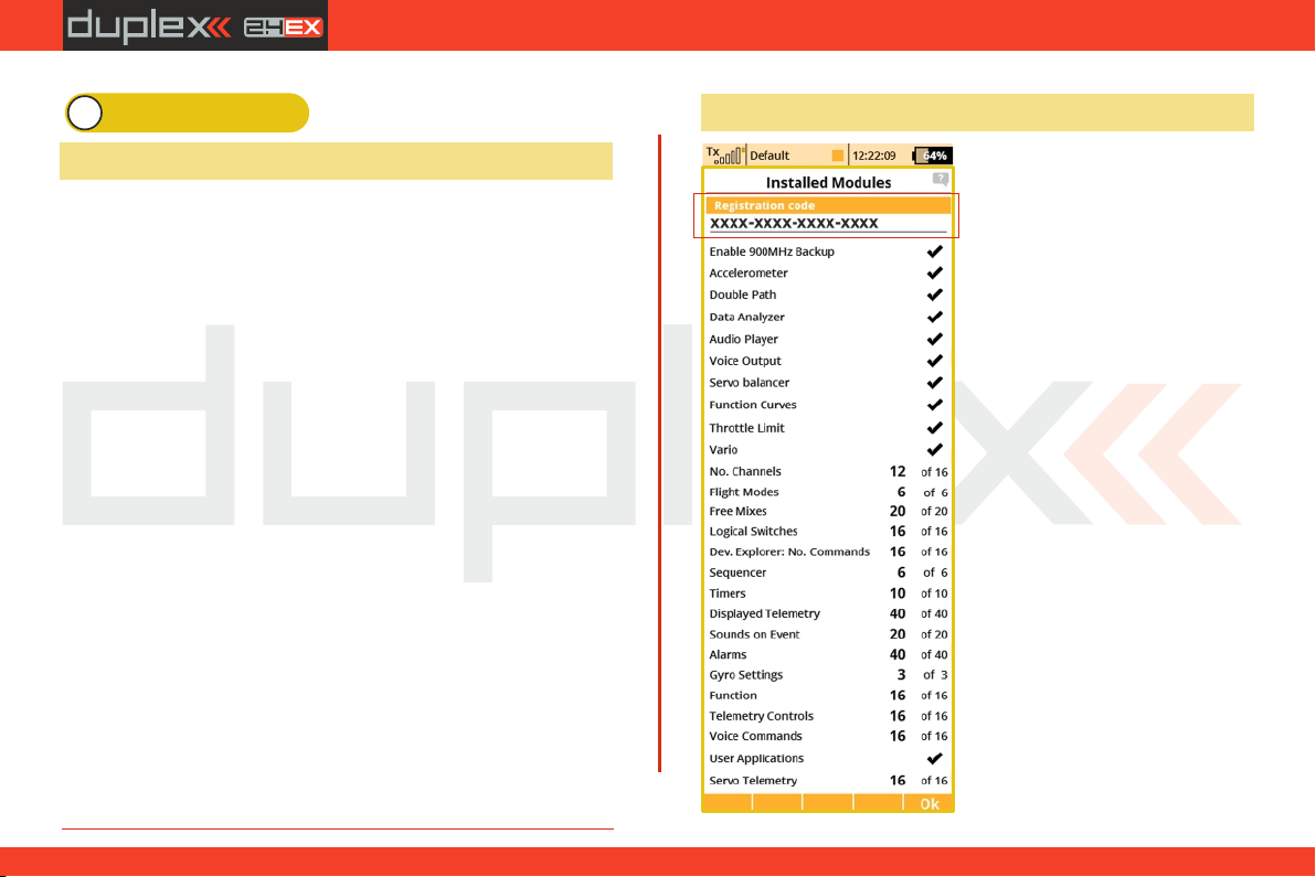
1.2 Activation method for software modules of JETI model
1. Make sure you have the most
current firmware version in your
transmitter.
2 . R e g i s t e r o n t h e s i t e
swshop.jetimodel.com.
3. After clicking on the „Register
new product“ button you will be
redirected to a form where you
enter a product type (DS-14),
followed by the „serial number”
(SN: xxxxxxxxx) (to be found on
the back of the transmitter behind
the screen) and then enter the „16
digit registration code” (xxxxxxxx-xxxx-xxxx) (see the menu
„System -> Installed Modules”
highlighted by the frame). After
registering your transmitter, you
can select individual function
module s that you wan t to
activate.
4. Mark selected modules and
proceed to checkout.
5. Then you will be asked to pay
9
1.1.
Page 10
computer radio control system
the relevant amount. After payment, a unique nontransferable file
named “Activation.bin” will be generated. It will then be sent to
your e-mail.
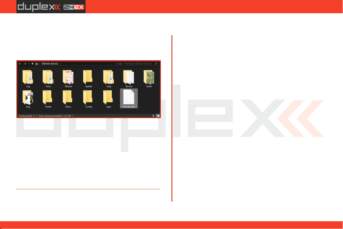
6. Connect the DS-14 to your computer and enable USB mode.
7. Copy the “Activation.bin” file to the transmitter SD card into the
root folder. The contents of the transmitter SD card can then look like
this:
8. Disconnect the transmitter from the computer (Do not forget to
confirm the safe hardware removal). Then confirm in your
transmitter that you want to update and restart it.
If the activation is successful, an informative table with a list of
modules appears immediately after switching on. Then it is
possible to operate the transmitter as usual.
EN
10
Page 11

computer radio control system
EN
1.3 Features
Duplex 2.4GHz – the DS-12 transmitters feature the Duplex 2.4GHz,
frequency hopping, digital, data stream system, originally
developed by JETI model in the Czech Republic. This system has
been reliably used for many years.
Duplex 900MHz NG (Next Generation) - the DS-12 transmitters
feature a backup wireless system for unmatched data transmission
safety and reliability.
Built-in Telemetry – from the start, the DS-12 transmitters were
designed and built with many attractive features and include the full
integration of all Duplex telemetry sensors.
Transmitters - the DS-12 designs use premium quality materials and
emphasize state-of-the-art appearance and user comfort.
Precise Gimbals – the transmitter gimbals are equipped with Hall
sensors and ball bearings for precision movement with an almost
unlimited lifespan.
Haptic feedback - the transmitter are equipped with shaking
vibration motor that can be used for alarm notifications, timers etc.
LCD Display – color 3.5" TFT LCD display with 320 x 240 resolution
which is highly visable under any light conditions.
Li-Ion Battery – provides a proven and reliable energy source with a
high capacity (6200mAh) and a long service life.
Easy Charging – simply connect the wall power supply, optional car
charger, or any 12V DC power supply to the transmitters charge port.
The DS-12 may also be charged through the USB to PC interface. The
charging progress is shown on the DS-12 display.
Integrated Antenna – the antennas are located behind fully
integrated cover in the DS-12 case for protection against mechanical
damage.
Large Memory – Internal SD card for storing models, sounds, and
telemetry data.
USB Connector – convenient connection to your PC. Fast firmware &
sound upgrades, telemetry data downloads.
Fast Navigation – 3D wheel-style interface combined with function
keys allow for speedy navigation within the DS-12 menu.
Digital Trims – fully programmable trims and a revolutionary
automatic trimming function.
Swappable and Assignable Switches – all of the switches on the DS12 transmitters (2 or 3-position) can be easily moved and assigned to
create a custom configuration that works best for your application.
Programming – the logical and intuitive transmitter firmware is
designed to be simple to use. Just follow the step-by-step screens.
The creation of a new model can be accomplished with just a few
easy steps.
Sounds/Alarms – the DS -12 transmitters are equipped with audible
alarms and also allows the use of user-recordable alarms and sounds
to keep you fully informed while also keeping distractions to a
minimum.
Integrated microphone with voice recognition capability - using
the integrated microphone you can easily prepare your own audio
files. Furthermore, you can teach the transmitter to respond to
several voice commands.
11
1.1.
Page 12
computer radio control system
EN
1.4 Manual Navigation
To make navigation faster, the DS-12 transmitter Instruction Manual
has been divided into 5 basic groups:
1. Introduction and product support.
2. Basic description and mechanical adjustments.
3. First time switch-on. Basic helicopter and airplane set up.
4. Advanced programming. Detailed descriptions.
5. PC upgrade/upload, safety information, and special mixes.
Important parts of the instructions are separated from the text
andhighlighted according to importance.
Advice Note Warning
Advanced modelers may want to begin with group 3 where you will
get all of the basic information for model setup. This is the quickest
way to understand the basic ideas of the DS-12 transmitter
programming and with this basic information you can begin to
create your own model. More advanced programming functions are
found in group 4. This is where you can find detailed descriptions of
all of the DS-12 functions. The last section provides detailed
description of firmware upgrades, downloads, and special mixes.
1.5 Technical Support
If you feel uncertain about how to set up particular transmitter
functions, do not hesitate to take advantage of our technical support:
1. Web Site
Either the JETI model (manufacturer) or your local distributor’s web sites
offer a wide range of support for the DS-12 transmitters. You will find
advice, tips or frequently asked questions (FAQ) which, in most cases,
contain the answers to your questions.
2. Distributor, Manufacturer
You may also find support at your local hobby shop, distributor, or
directly with the manufacturer JETI model s.r.o.
3. Service and Warranty Coverage
JETI model CZ exclusively warranties that the products purchased will
be free from defects in materials and workmanship for a period of 24
months from the date of purchase by the customer. This warranty
covers only those products purchased from an authorized JETI model
CZ distributor or dealer. Third party transactions are not covered by this
warranty. Proof of purchase is required for warranty claims. Repair or
replacement decisions are at the sole discretion of JETI model CZ or an
authorized service provider. This warranty does not cover cosmetic
damage or damage due to an accident, misuse, abuse, negligence,
commercial or research use, or modification of or to any part of the
product. This warranty does not cover damage due to improper
installation, operation, maintenance, or attempted repair by anyone
other than JETI model CZ or an authorized service provider.
JETI model CZ reserves the right to change or modify this warranty
without notice and disclaims all other warranties, expressed or
implied.
12
1.1.
Page 13
computer radio control system
Basic technical parameter
DS-12
RF module 900MHz
(863-870 MHz - EU)
(902-928 MHz - EU)
m
Stick material Multimode
Plastic
Resolution of sticks
4096
Sticks HALL sensors
l
Internal memory, SD cart
8 GB
RF modul 2.4 GHz
1
Number of antennas
3
LCD
3,5" 320x240px
color high contrast
Weight [kg]
0.7
Dimensions [mm]
194x215x55
Battery pack [mAh]
Power Ion
6200
EN
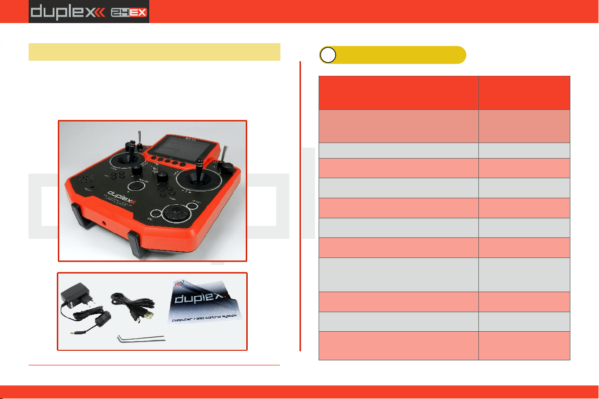
1.6 DS-12 Package Contents
1. 2. 3. 4. JETI DS-12 Transmitter, Wall Power Supply, USB PC Cable,
Installation Key Set , Cleaning Cloth, Instruction (HEX 1,5; TORX 10) 5.
Manuals,
1
2
3
5
4
2 System Specifications
1. 2.
m Extension l Contains
13
Page 14
computer radio control system
EN
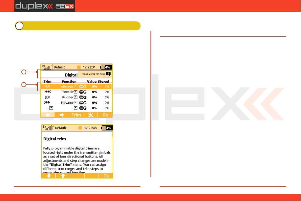
3 Help mode
It is possible to call up the help mode for each item where a "question
mark" icon appears in the upper right corner of the screen . If you see (1)
this icon, you can press the "menu" button briefly to call up the help
mode for the current item you have highlighted in the respective
transmitter menu .(1)
1
2
This help mode is available in FW min. v5.00. We recommend update
your transmitter by Jeti Studio.
14
2.2.
Page 15
computer radio control system
EN
4 Description of Transmitter DS-12
10
7
2
8
25
19
16
3
21
11
24
10
22
20
4
23
12
17
18
5
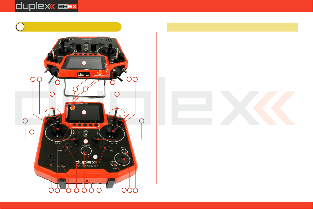
4.1 Control Identification DS-12
1. Right Stick 1, 2 – the DS-12 Transmitter Supports Modes 1-4, see Control
Sticks -> mode change
2. Left Stick 3, 4 the DS-12 Transmitter Supports Modes 1-4, see Control
Sticks -> mode change
3. Swappable and Assignable Switches: Sa, Sb, Sc, Sd, Se, Sf
4. Digital Trims for the Left Stick T3, T4
5. Digital Trims for the Right Stick T1, T2
6. Right Rotary Control Knob 5
6
1
3
9
15
14
13
7. Left Rotary Control Knob 6
8. Rotary Control Knob 7
9. Rotary Control Knob 8
10. LCD Display
11. Function Buttons F1 – F5
12. Transmitter On/Off Power Switch
13. 3D Control Selector
14. Menu Button
15. ESC Button
16. Shows the 2.4GHz Antenna but NOT the handle.
Add the handle and assign it a number and pointer in the photo.
17. Charge Jack
18. USB PC Interface
19. PPM Input/Output
20. ON/OFF & Charging LED Indicators
21. Speaker
22. Neckstrap Hook
23. Earphone Jack
24. 900 MHz Antenna
25. Microphone
15
2.2.
Page 16
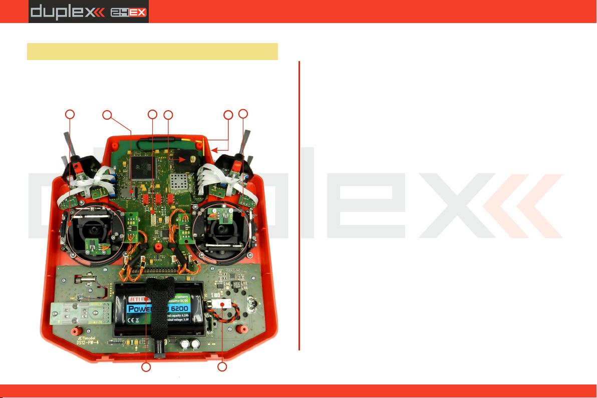
4.2 Assembly Identification
26. Battery Connector
27. Transmitter Battery Pack
28. PPM Output Connector
29. Left Gimbal Assembly
30. Right Gimbal Assembly
29
31
computer radio control system
31. Micro SD Card
32. 2.4GHz Antennas
33. 900 MHz Antenna
28
33
30
32
EN
27
26
16
2.2.
Page 17
computer radio control system
EN
4.3 Control Stick Assembly
Note:
Warning:
4.3.1 Control Stick Length Adjustment
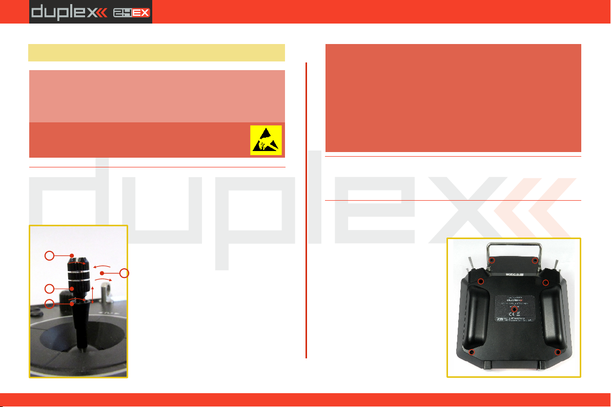
The stick length is adjustable to suit your flying style. The stick end
separates into two parts.
When handling with back cover removed always
switch off the transmitter and disconnect the
battery (unplug the connector). Also do not connect
the charging adapter or the USB cable.
Restrict your contact with the printed circuit
boards to a minimum. You can damage your
radio by electrostatic discharge!
1. Hold the top part of the
1
2
3
stick and firmly and unscrew (turn it
anticlockwise).
2.Turn the stick end clockwise to
4
sh o r ten or coun tercl o ckwise to
lengthen the overall stick length.
3. Adjust the lower part to support
the top part of the stick end.
4. Finally secure by tightening both
parts to each other.
Warning:
If you have installed optional sticks with switch or
button ends; make sure that while adjusting the stick
length you observe the wires that pass through the
stick shaft and through the gimbal opening in order
to prevent damaging the connecting cables. The
safest method is to remove the small set-screw from
the side of the stick housing to allow the switch or
knob internals to remain stationary while you rotate
the stick housing for height adjustment. (4.3.7)
4.3.2 Control Stick Angle Adjustment
It isn't possible to adjust the angle of rotation of control stick in the
DS-12 transmitter.
4.3.3 Control Stick Tension Adjustment
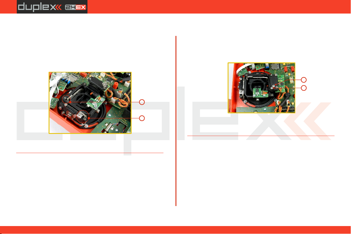
The stick gimbal tension is fully adjustable for each axis. This allows
you to fully customize your
radio‘s control feel. Simply
adjust each gimbal‘s spring to
your desired tension.
1. Switch off the transmitter
and remove the 7 screws
t h a t s e c u r e
the radio back cover. Next,
remove the radio back
cover.
Be sure to disconnect
the transmitter battery
pack connector.
17
2.2.
Page 18
computer radio control system
EN
2. Use indicated machine adjustment screws to change the
desired spring tension. By turning the screw countercloc
kwise, you will loosen spring tension. As a result the moving
resistance of the control stick will decrease.
By turning the screw clockwise, you will tighten spring tension. As
a result the moving resistance of the control stick will increase.
2
2
3. Reconnect transmitter battery pack and reinstall radio back
cover and cover screws.
4.3.4 Ratchet Tension Adjustment
Whether you prefer smooth throttle feel or ratchet throttle feel, you
can adjust the DS-12 transmitter either way you like allowing you to
fully customize your radio‘s feel. Each tension is set by a different
machine screw.
1. Switch off the transmitter and remove the 7 screws that secure
the radio back cover. Next, remove the radio back cover. Be sure
to disconnect the transmitter battery pack connector.
2. For ratchet tension adjustment use the machine screw . “A”
Turn slowly (counter-clockwise) until you achieve the desired
ratchet tension. For smooth tension adjustment, use the
machine screw Turn slowly (clockwise) until you achieve “B”.
the desired smooth tension.
A
B
3. Reconnect transmitter battery pack and reinstall radio back
cover and cover screws.
18
2.2.
Page 19
computer radio control system
EN
4.3.5 Throttle stick travel adjustment
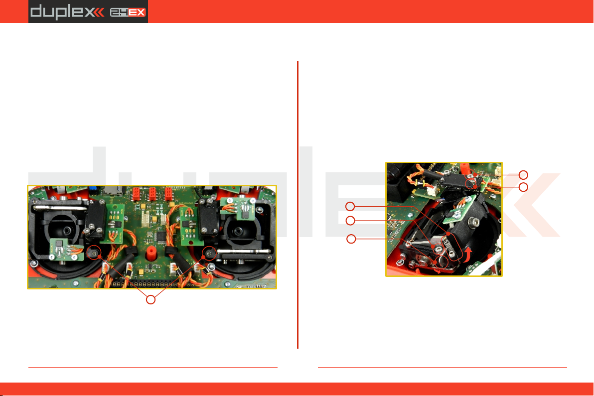
The throttle stick travel is adjustable to suit your flying style.
1. Switch off the transmitter and remove the 8 screws that secure the
radio back cover. Next, remove the radio back cover. Be sure to
disconnect the transmitter battery pack connector.
2. Use indicated machine adjustment screws to limit the throttle
stick travel. By turning the screw clockwise, you will shorten the
throttle stick travel.
3. Reconnect transmitter battery pack and reinstall radio back cover
and cover screws.
2
After making a limit change to the throttle stick travel you must
recalibrate the transmitter stick in the software menu, see section
9.6.3 –Calibration of Proportional Controls.
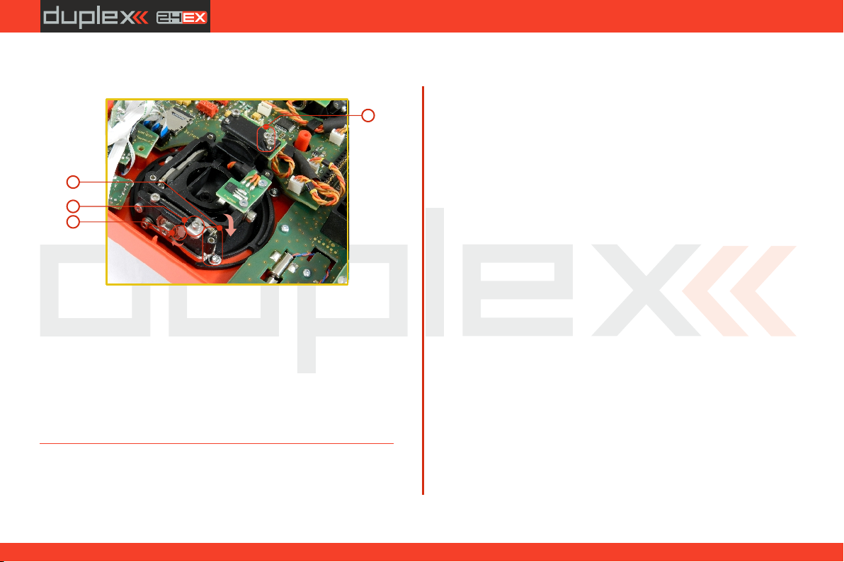
4.3.6 Changing the transmitter mode
The transmitter is equiped with universal multimode gimbals. Both
gimbals are identical and can be adjusted mechanically for modes 1-
5. After mechanical adjustment it is necessary to set a specific
transmitter mode in the menu System – Configuration – Stick mode
1-4.
To change the quad sticks settings, unscrew the back cover of the
transmitter and disconnect the battery connector.
A. Setting the multi-mode gimbal into the mode without
locking the middle position - gas
E
D
2
1
3
A
B
5
5
C
1. A.Loosen the screw
2. C. Lift the lever B so as it is possible to arrest the lock
3. C Turn the lock 90° in the direction of the arrow and arrest the
lever in the upper position. B
4. A. Tighten the screw
5. D E Tightening the the screws and sets the desired tension with
steps and smooth brake.
19
2.2.
Page 20
computer radio control system
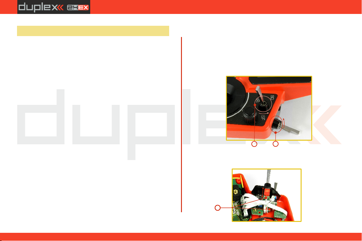
B. Setting the multi-mode gimbal into the mode with locking
the middle position - elevator
5
E
D
2
EN
1
3
1. A.Loosen the screw
2. B. Slightly lift the lever
3. C B Turn the lock in the direction of the arrow and arrest the lever
in the upper position.
4. C Move the lever in the direction of the arrow to release the lever
B.
5. A. Tighten the screw
6. Loosen the screws E and D in a position so that tension is removed
from the stick.
A
C
B
20
2.2.
Page 21
computer radio control system
EN
4.4 Swappable and Assignable Switches
One of the most important features of a JETI transmitter is the switch
function assignment flexibility. The exact type of switch can be set in
„menu->advanced->properties->sticks-switches->setup”. There
are many switches available to suit different needs. See your Jeti
retailer for switch availability.
You may either swap the existing switches around or take advantage
of the optional accessories and create your own custom
configuration.
Factory Switch Configuration for the DS-12 Transmitter
Sa - 3 - position short switch
Sb - 2 - position long switch
Sc - 2 - position long switch
Sd - 2 - position long switch
Se - 3 - position long switch
Sf - 2 - position short switch
4.4.1 Switch Removal Procedure
1. Switch off the transmitter and remove the 7 screws that secure
the radio back cover. Next, remove the radio back cover.
Be sure to disconnect the transmitter battery pack
connector.
2. With the specialized wrench (not included) carefully loosen and
remove the switch installation nut.
2
3. Hold the switch from the back side of the transmitter and pull it
towards you, so that the switch is released from the body of
transmitter.
2
21
3
2.2.
Page 22
computer radio control system
EN
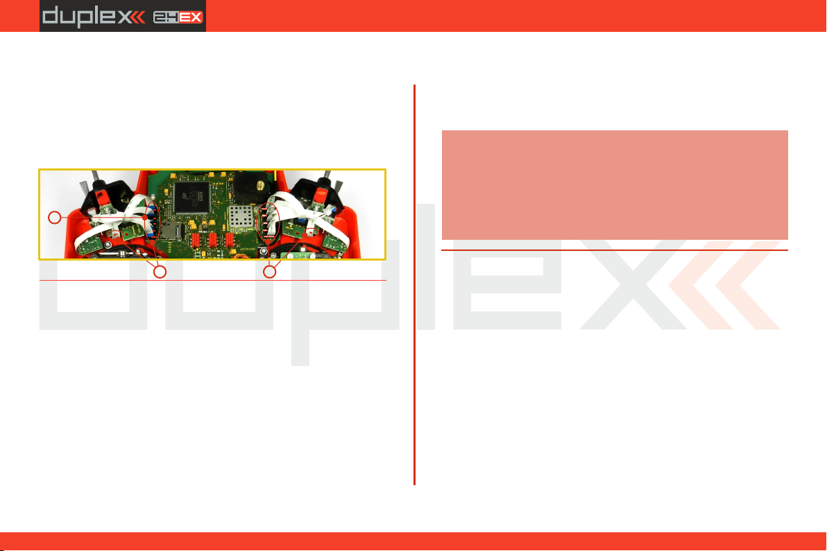
4. Disconnect the flat flexible cable from its connector on the
main board.
The flat flexible cables that link the main printed circuit board
with the switches are oriented as shown in the picture (4a).
The wire is always color coded on one side of both ends (4b).
The markings must be oriented as shown below.
4a
4b
4b
4.4.2 Assembly Procedure
1. Insert the flat flexible cable to the switch connector of the
switch. See the orientation above.
2. Push the switch into its spot in the transmitter housing.
3. Tighten the switch installation nut from the front of the
transmitter. Use the specialized wrench (not included).
4. Connect the flat flexible cable to the main printed circuit board
of the transmitter. See the orientation above. The cable has to
be inserted to the connector that matches the position on the front
panel where the switch is installed.
5. Reconnect transmitter battery pack and reinstall radio back
cover and cover screws.
After you turn on the transmitter for the first time after any switches
have been modified, you will notice that the configuration for a
selected model no longer matches.
Note:
When replacing the switch it is also necessary to Sb
remove the switches and from the transmitter Sa Sc
body.
When replacing the switch it is also necessary to Se
remove the switches and from the transmitter Sd Sf
body.
22
2.2.
Page 23
computer radio control system
EN
4.5 Digital Trims
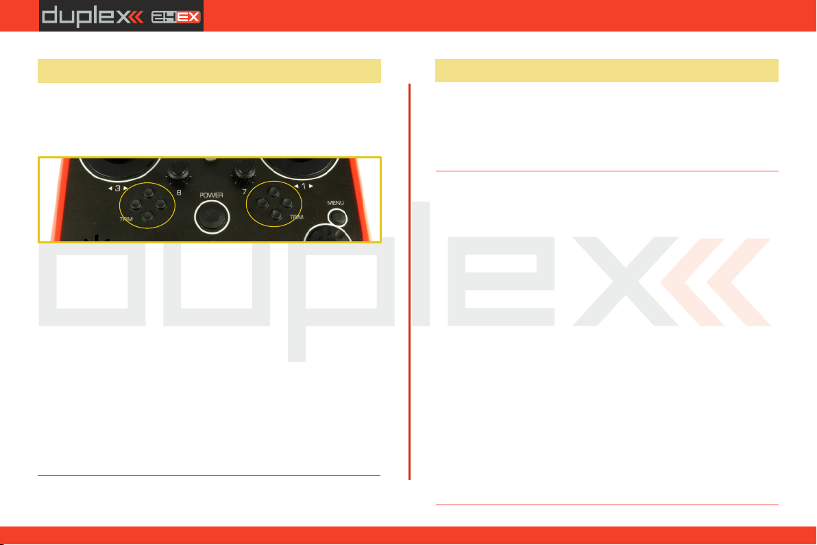
Transmitter gimbals are used for controlling the basic flight
functions like throttle, roll(aileron), pitch(elevator), and yaw(rudder).
Immediately under the transmitter gimbal sticks you can see four
push-buttons which are the programmable, digital trim buttons.
The digital trims are used for fine trimming of the flying model. When
the transmitter is turned off, the trim values are stored in memory
and are recalled when the system is turned back on.
Every model has its own trim setup. Also all flight modes may be
configured to use different trim configurations. By pressing one of
the buttons, the screen will automatically change to display the
graphic position of that trim. The transmitter trims feature an
acoustic step and center beep alarm.
4.6 Transmitter Battery Pack
The DS-12 transmitter is powered by a Li-Ion type battery pack and
comes equipped with its own built-in advanced batter y
management and charging circuit. In switched-on position, the
transmitter LCD display shows the status and condition of the
battery pack. The Li-Ion battery is factory installed.
4.6.1 Charging
The DS-12 transmitter can be charged with the included wall power
supply, optional car charger, or through the built-in USB port. For fast
charging use the included wall power supply. Charging time is
around 3 hours. During the charging process the transmitter can be
in switched-on or off position. The charging status is clearly shown
by lit green LED. If the transmitter is switched on during the charging
process you can see the charging progress directly on the LCD
display.
Transmitter Charging:
1. Plug-in the included power supply to a wall outlet.
2. Plug the main charging connector into the transmitter. If the
green LED goes out, the transmitter is not fully charged. The
red LED indicates the battery charging status.
• Discharged battery – red LED is slow blinking, the green LED
is OFF
Close to full charge – red LED is permanently ON, the green •
LED is OFF
Fully charged battery – the green LEDs are ON•
23
2.2.
Page 24
computer radio control system
EN
4.6.2 Battery Replacement
Should you decide to replace the transmitter battery, please follow
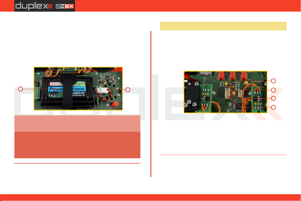
these steps:
1. Switch off the transmitter and remove the 7 screws that
secure the radio back cover. Next, remove the radio back cover.
2. Disconnect the transmitter battery connector.
3. Loosen the battery fastening strap and remove the battery.
3
If the transmitter battery has been disconnected for
Note:
longer than 1 minute, the time and date will be deleted.
Warning:
DS-12 transmitters should only be operated only
with original or manufacturer approved battery
packs. The use of other battery packs will void the
warranty.
2
4.7 PPM Input/Output Connector
The PPM output is accessible via connector labeled "B“. This
connector features the non-stabilized battery voltage output in the
range of 3.2V - 4.2V (max. 1A) which can be used as power supply for
the connected HF module as well as for the PPM signal output. The
transmitter output functions are in the form of a standard PPM
signal.
4
3
2
1
1. PPM input (3V logics)
2. Positive (+) pin
3. Negative (-) pin
4. PPM signal output (3V logics, configurable in
„System->Configuration”)
24
2.2.
Page 25
computer radio control system
EN
4.8 Handling
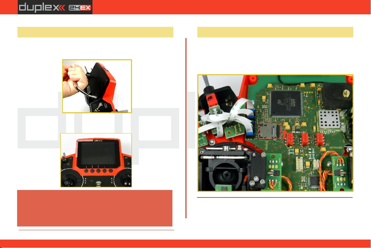
The DS-12 is equipped with a handle for practical manipulation as
shown in the picture.
The transmitter 2.4GHz antenna locations are shown in the picture
below.
Warning:
Before each flying session, and especially with a
new model, it's important to perform a range
check. If you are operating a model with a DS-12
transmitter do not shield and avoid contact of the
transmitter antennas (see Photo)with your body.
4.9 Change SD Card
Disconnect the battery plug .
To open the SD card holder, use a fingernail to push the metal frame
to the right and then lift it carefully . The micro SD card can now be
removed . For installation, proceed in the reverse order .
[
25
2.2.
Page 26

computer radio control system
EN
5 RF Transmitter Modules
In order to achieve the highest transmission quality and reliability of
the DS-12 transmitters, we have decided to equip the radio with two
independent transmitter modules (DUPLEX 2.4GHz and 900MHz
NG). The transmitter modules have separate antennas. From the
point of transmission they are fully independent from each other.
The RF modules of the transmitter can operate in following modes:
• "Default“mode – the 2.4GHz Duplex module communicates
with the receiver using its two independent antennas. This
improves safety and helps to cover dead angles as well.
• "Double Path“m ode – the trans mit t er RF mod ule
communicate independently with two different receivers. The
receivers can be interconnected via an intelligent synthesizer,
for instance the JETI Enlink, or the basic control functions can
be divided between two independent receivers. In this mode
the 2.4GHz Duplex module communicates independently
with two receivers. This greatly improves safety and reliability
since both receivers communicate independently with the RF
module.
• „Student“mode – the 2.4GHz Duplex module is assigned to
commu nica te wit h the instructo r tran smitter o nly.
Communication with the model takes place via instructor’s
transmitter only. If you operate two of the DS-12 transmitters,
one of them in the "Instructor“ mode and the other one in the
"Student“ mode, the transmitters communicate between each
other via cable connection.
• Back-up Transmitter Module
The DS-12 are equipped with a wireless backup system . This
works on the 868MHz ( EU ) or 915MHz ( US, AU, JP ) band . This
backup system can optionally be used to the "standard" and
"2-way RF" modes. So it is not designed as a single transmission
path and provides additional redundancy in addition to the
2.4GHz system .
26
2.2.
Page 27
computer radio control system
EN
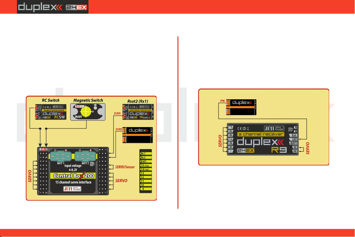
Recommended connection for Rsat900 NG as a backup receiver
with a Central Box
• Always connect the RSat2 or R3/RSW as the primary receiver in the
“RX1” slot of the Central Box.
• The RSat900 NG is connected to the " Rx2 " slot of the Central Box
• Both receivers are set to EX Bus output.
Rsat 900 NG (Rx2)
E
1
SATELLITE RECEIVER
I
/
R 900 NGsat
0
Connecting the RSat 900 NG directly to a Primary receiver :
• The RSat900 receiver is plugged into the “Sat1” slot of the primary
receiver.
• The RSat900 NG receiver is set to PPM output and the primary
receivers “Sat1” slot is set to PPM input.
Rsat 900 NG (Rx2)
E
1
SATELLITE RECEIVER
I
/
R 900 NGsat
0
27
3.3.
Page 28
computer radio control system
EN
6 Transmitter Powering ON/OFF
6.1 Transmitter Powering-ON
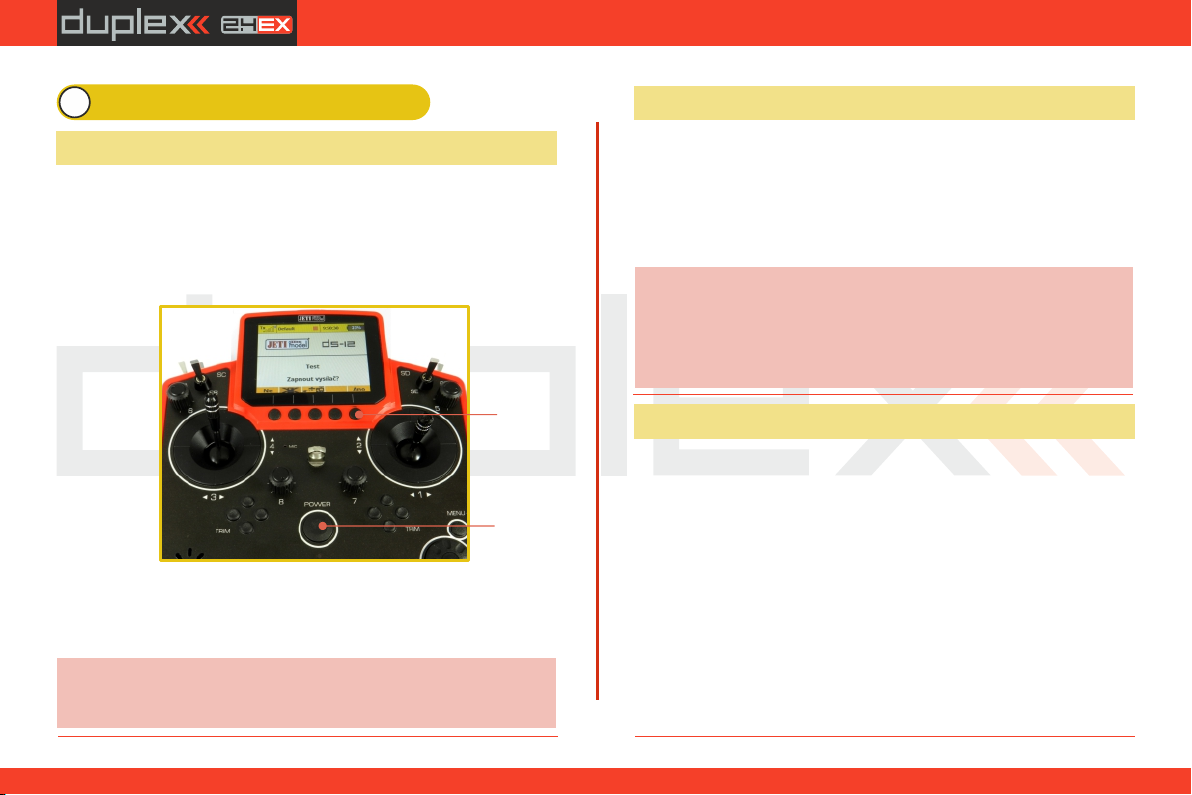
Switching-on is achieved by pressing and holding the "Power“
button . The green LED turns ON and the initial screen appears on (1)
the LCD display. At this point transmitter is waiting for final
confirmation – press the F5 (Yes) button . After confirmation, the (2)
main screen is displayed and the transmitter is ready. The power-on
status of the DS-12 transmitter is indicated by the lit green LED.
(2)
(1)
* If you do not confirm powering-on witinin a certain time limit, the
transmitter will turn off automatically. In the DS-12 transmitter setup
you may disable the confirmation by changing in the setup menu
"Main menu->System-> Configuration->Fast switch-on“.
We recommend that you leave the transmitter with the switch-
Advice:
on confirmation enabled, as this function prevents accidental
turning-on and discharging of the transmitter battery.
6.2 Transmitter Turning-OFF
The transmitter is switched-off by pressing the "Power“ main
button. Before complete power-down is achieved you will be asked
for additional confirmation. In case of an emergency, a fast turn-off
can be achieved by simultaneously pressing and holding the
"Power“ and "esc“ buttons. NEVER use this alternative during
normal working conditions.
Advice:
If you want to find out the battery status on a switched-off
transmitter just push the button "Power“ and the initial screen
with the battery status will appear. If you do not confirm
turning-on, the transmitter will shut down automatically.
During the charging process this function is always activated.
6.3 Transmitter Restart
In case of erratic behavior we recommend that you restart the DS-12
to reboot the operation system.
1. Standard switch-OFF and ON with main „Power“ button.
2. If necessary, use the Emergency Switch-OFF by simultaneously
pressing and holding the „Power“ and „esc“ buttons.
3. Disconnect and reconnect the transmitter battery connector.
[ Remove the screws that secure the radio back cover. Next, remove a)
the radio back cover, Disconnect the transmitter battery connector, b) c)
Press the "Power“ button to discharge the internal capacitors, d)
Reconnect the transmitter battery, Reconnect transmitter battery e)
pack and reinstall radio back cover and cover screws, Restart the f)
system. ]
28
2.2.
Page 29
computer radio control system
EN
7 Initial switching-on
Turn the transmitter on by pressing and holding the „Power“ button
for a couple of seconds and then press the "F5 (Yes)" button to
confirm, see chapter 6.1. The display shows the Main screen and
displays the currently loaded model aircraft.
You can also immediately select a different model after the
transmitter starts by pressing the "F3" button.
By pressing the "F2" button you are able to disable the logging
feature for a current session. If you are just making adjustments to
the model configuration, press the "F2" button and confirm. The
logging will be disabled until restart of the transmitter.
To make the start-up screen visible, in the Configuration Menu, you
have to select "No" for the "Disable startup question" option.
7.1 Main display
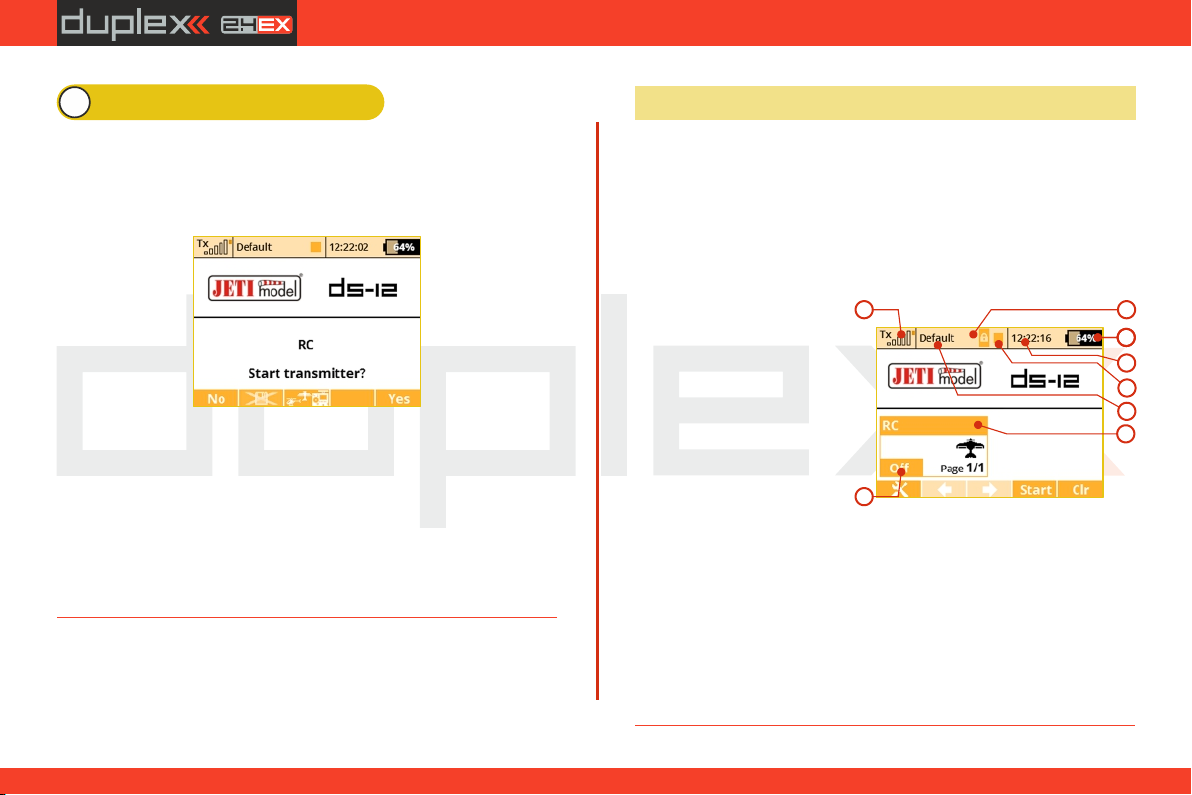
The main screen displays basic information about operation of your
transmitter, such as the battery level, time, flight mode, etc. This
screen will also display the user defined information you want to
monitor, for example: stopwatch, telemetry values, etc. The main
screen consists of three main sections: the status bar, the desktop
and the lower bar.
The status bar at the top of the main display displays the following
information:
1. Signal strength
2. Battery status
3. Time
4. Telemetry recording icon
5. Model Name
6. Name of actua l flight
mode
7. Throttle Lock
8. Motor cut-off indication, idle
The Desktop is the largest part of the screen. This is where you can
see your telemetry data and where any programmed alarms are
displayed. The Desktop displays your user-defined information
through the use of multiple pages. As you add or remove telemetry
items or alarms, the number of available pages will automatically
increase or decrease as needed.
1
8
7
2
3
4
6
5
29
3.3.
Page 30
computer radio control system
EN
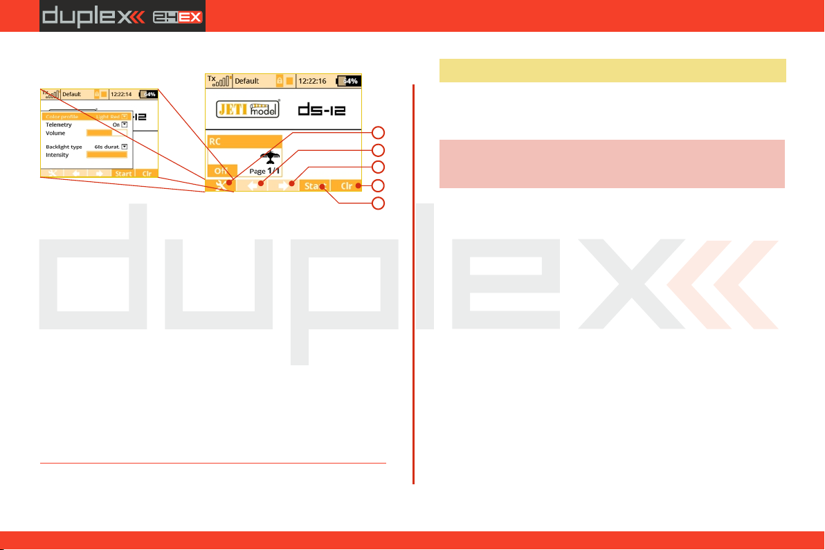
The lower bar is found at the bottom of the main display.
The lower bar shows:
1
2
3
4
5
1. Tools - fast transmitter setup: Color profile, Telemetry,
Volume, Backlight duration, brightness
2. Left Arrow-move left within the desktop pages.
3. Right Arrow-move right within the desktop pages.
4. Clr-resets the timers or opens the Data Analyzer application in
the main desktop window.
5. Stop/Start-begin and end flight timer, triggering timers or
telemetry recording.
Use the corresponding F1-F5 buttons to select these options
From the main display you may access the main menu by pressing
the "menu“ button. To return from the main menu press either the
"menu“ or "esc“ button.
From the main display, when you push any of the trim buttons or the
3D button the "Trim menu” will be displayed.
7.2 Navigation in the Menu
7.2.1 Navigation
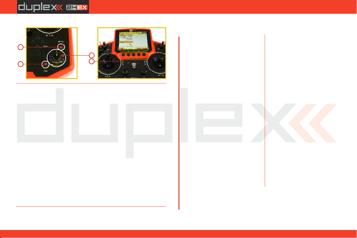
1. The „menu“ button allows you to switch between the main
display and the transmitter‘s main menu.
Also, If you push this button while turning the 3D Control
Advice:
Selector to edit values, the values can be changed faster. With
the menu button pressed, 10 more values are changed per turn.
2. The "esc“ button allows you to move one level back within the
menu. If you push this button while you are editing a value you
will return one menu level and the edited value will NOT be
stored.
3. 3D Control Selector
3a - by turning the selector counter-clockwise you will move
up in the menu. Turning the selector this direction will
also decrease any value you are editing.
- by turning the selector clockwise you will move down in 3b
the menu. Turning the selector this direction will also
increase any value you are editing.
- by pressing the selector you will confirm your 3c
choice/enter the selected menu.
4. The „F1 - F5“ functions buttons located below the display are
used to select various options based upon the current display.
30
3.3.
Page 31
computer radio control system
1
2
7.2.2 Browsing through the Menu
The current selection within the menu (cursor) is designated by
reversed text/shaded graphics. By turning the 3D control selector
left/right you will move through the lines of a menu.
To select an item, first highlight the line and then press the "3D
button“, to select the line. Rotate the 3D control selector to
highlight your selected item within the line, then press the "3D
button“ to select the item. Rotate the 3D control selector either left
or right to change the value of your chosen item. By pressing the "3D
button“ again you will confirm the storage of your selected value
and go back to your previously selected menu item. If you want to go
back to select another line within the previous menu press the "esc“
button.
Note: For each press of the "esc“ button, you are taken back one
menu level.
3c
3a
3b
3
4
7.2.3 Basic Menu Structure
* Model
- Select Model
- New Model
- Basic Properties
- Model Image & Colors
- Functions Assignment
- Servo Assignment
- Servo Setup
- Device Explorer
* Fine Tuning
- Flight Modes
- Digital Trim
- Flight Mode Trim
- Dual Rate/Expo
- Function Curves
- Aileron Differential
- Gyro Settings (Heli)
- Throttle Limiter (Heli)
- V-Tail, Delta Mix, Ailevator Mix
(Aero)
- Butterfly (Aero)
- Snap Roll
- Free Mixes
* Advanced Properties
- Other Model Options
- Sticks/Switches Setup
- Wireless Modes/Trainer
- Logical Switches
- Sound on Event
- Sound of Prop. Controls
EN
- Telemetry Controls
- Voice Commands
- Sequencer
- Accelerometer
* Timers/Sensors
- Timers
- Alarms
- Vario
- Voice Output
- Sensors/Logging Setup
- Displayed Telemetry
- Main Screen
* Applications
- Data Analyzer
- Audio Player
- JETIBOX
- Games (Snake, Tetris, Chess...)
-Image Slideshow
-Microphone
-User Applications
* System
- Configuration
- Servo & Range Test
- View Inputs
- Receiver Output
- System Sound
- Sound Volume
- USB
- Info
31
3.3.
Page 32
computer radio control system
EN
7.3 Model Set-up Guide
In this section we will guide you, step by step, through the process of
creating a new model airplane and helicopter. Each step of the guide
will be complete with associated transmitter menu photos. If you
follow the step by step guide you should become familiar with how
to create a model profile. You may even use these concepts and the
"General“ model type to create your own, user-defined model
profile.
7.3.1 Airplane
Let’s create a simple model airplane. Our example will be a motor
glider with ailerons controlled by two servos, an elevator and a
rudder each controlled by one servo.
Servo assignment:
1. Throttle
2. Aileron 1
3. Aileron 2
4. Elevator
5. Rudder
Before you begin creating a model, make sure that you have set up
the correct transmitter mode in "Main menu -> System ->
Configuration -> MODE 1-4“. The basic, standardized, assignment
of transmitter inputs to flight controls are based upon this selection.
First it is necessary to create a model in the transmitter and then bind
the DS-12 transmitter with the receiver which will control the given
model. See chapter 8.3: „Receiver->Binding”.
32
Warning:
For safety reasons we recommend first removing the propeller.
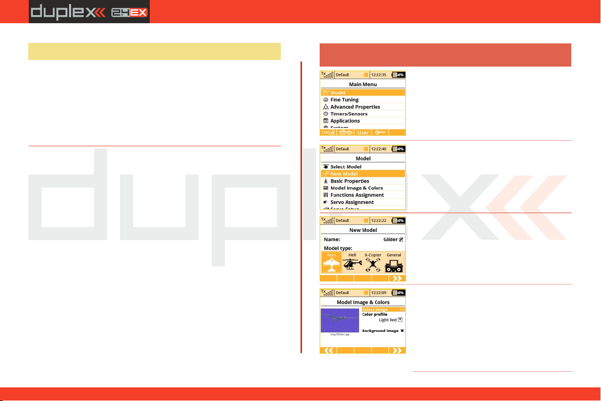
1. Switch-on the transmitter. In the main
display push the key „menu“. Select the
item „Model“ and push the „3D button“.
2. Select the item „New model“ and push
the „3D button“.
3. Enter the name of your model and press
„F5(OK)“ (Note: you must enter a model
name to proceed.) Then select the model
type „AERO“. Confirm by pushing the
„F5(Next)“ button.
4. Choose an optional model image and
color profile according to your personal
preferences. The images must be loaded to
the internal SD card before you use
them.You can skip this step by pressing "F5
(Next)" button.
3.3.
Page 33
computer radio control system
EN
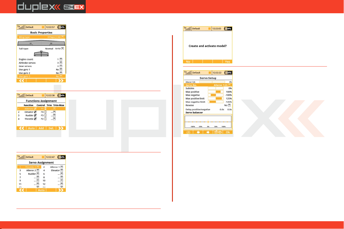
5. Select your wing type. Because this
example has 2 aileron servos, select „Wing
type“ 0FLP/2WING. Do not change any
other setup items like tail assembly,
number of motors, number of spoilers or
number of landing gear servos. Continue
by pushing the „F5(Next)“ button.
6. This page displays the flight control
functions and their transmitter switch
assignments. Here you can verify that your
flight control functions are correctly assigned
to the transmitter switches/sticks. If they are
not, check and make sure that you have
selected the proper transmitter mode.
Confirm the assignments by pushing the
"F5(Next)“ button.
7. This page displays the assignment of
functions to your receiver outputs (servos).
You may change the assignments by editing
the output assignment for each receiver
channel. Otherw ays co nfi rm w ith the
"F5(Next)“ button.
8. The screen will now display a request which
asks if you really want to create and activate
the new model. Confirm with the "F5(Yes)“
button.
9. The Servo Setup menu is where you set the
servo neutral positions, servo output travel
limits, servo reversing, delay etc. You will
come back to this menu after binding the
receiver with your transmitter. Press the
"F5(OK)“ button and you are taken to the
main screen where your new model is
displayed in a desktop page.
Bind transmitter with the receiver, see
chapter 8.4 Receiver->Binding.
Once your transmitter has been bound with the receiver and you have
re-applied power to the receiver, the last setup phase is the tuning of
your servo output functions, see chapter 7.3.5 Setup of receiver
outputs.
With this type of wing configuration there is usually a mixer used to also
raise the ailerons as spoilers (spoilerons). Follow the steps below the set
up this mixer. In this example we will use the "right side control
lever(5)“ for the proportional control of the spoilerons.
33
3. 3.
Page 34
computer radio control system
EN
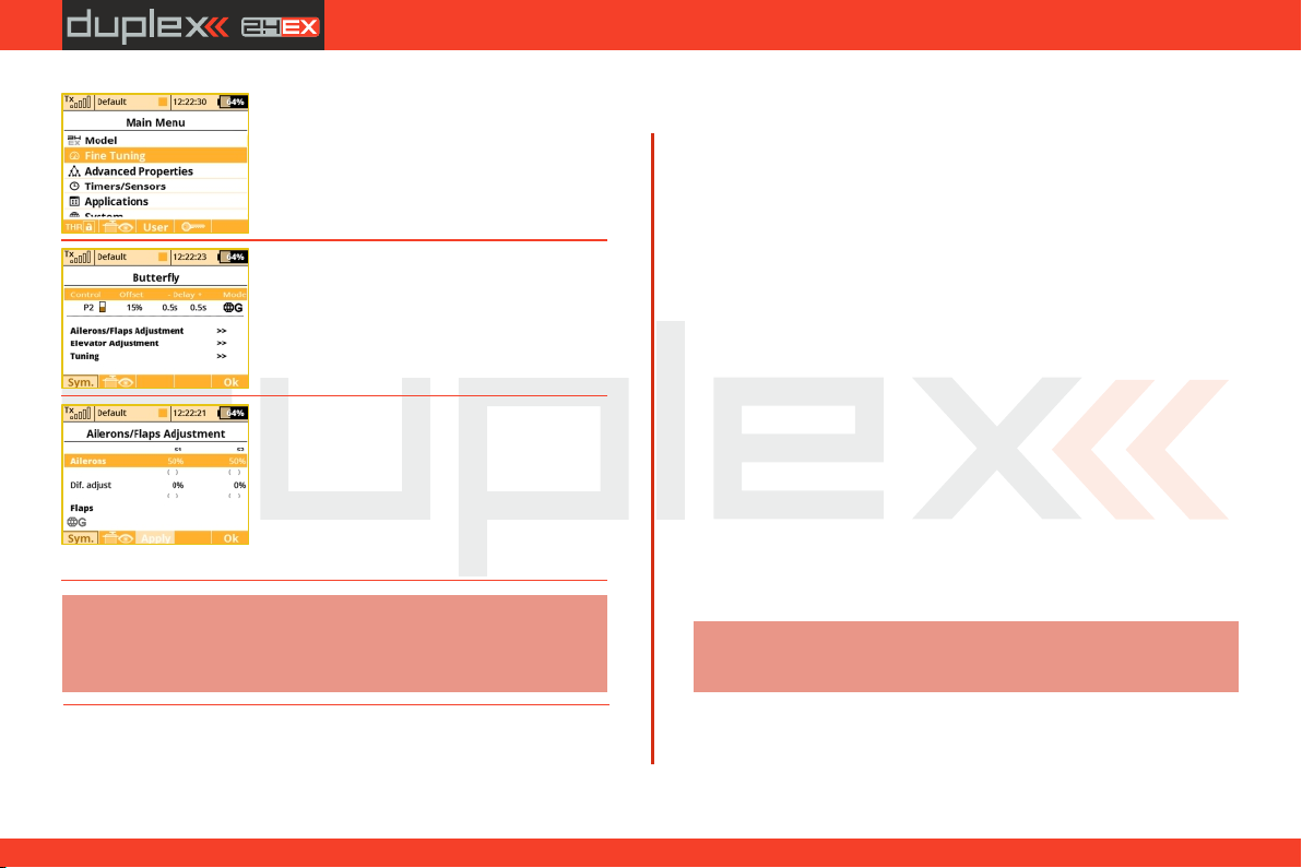
a. From the main screen, push the „menu“
button. Select „Fine tuning“ and push the
„3D button“.
b. Next, select „Butterfly“ and push the „3D
button”.
c. In the first menu line push the "3D button“
,select 'Switch“ and push the "3D button“
again. Next, move the "right side control
lever(5)“. Confirm with the "F5(OK)” button.
The last step in this menu is to set the amount
of travel that your ailerons will move as
spoilerons (or flaperons) and to set any
desired elevator compensation.
Note:
When setting up your spoilerons be sure that the ailerons still
have enough travel to control your airplane when the spoilerons
are deployed. In this menu the "(Sym) F1“ button will link or
unlink the spoilerons if you need to set them independently
7.3.2 Helicopter
Let’s create a simple model helicopter. In this example, the
helicopter is controlled by a swash plate with three servos at 120°
orientation and the motor has no governor.
Servo assignment for the receiver channels:
1. Throttle
2. Elevator (Swash 1F)
3. Collective (Swash 2L)
4. Aileron (Swash 3R)
5. Rudder (Yaw)
6. Gyro(Gyro sens.)
Before you begin creating a model, make sure that you have setup
the correct transmitter mode in "Main menu -> System ->
Configuration -> MODE 1-4“. The basic, standardized, assignment
of transmitter inputs to flight controls are based upon this selection.
First it is necessary to create a model in the transmitter and then bind
the DS-12 transmitter with the receiver which will control the given
model. See chapter 8.3: „Receiver->Binding”.
Notice:
For safety reasons we strongly recommend removing the
main/tail blades or disconnecting the motor when working
with an electric helicopter.
34
3. 3.
Page 35
computer radio control system
EN
1. Switch on the transmitter. In the main
display push the key "menu“. Select the
item "Model“ and push the "3D button“.
2. Select the item „New model“ and push
the „3D button“.
3. Enter the name of your model and press
"F5(OK)“ (Note: you must enter a model
name to proceed.) Then select the model
type "Heli“. Confirm by pushing the
"F5(Next)“ button.
4. Choose an optional model image and
color profile according to your personal
preferences. The images must be loaded to
the internal SD card before you use
them.You can skip this step by pressing "F5
(Next)" button.
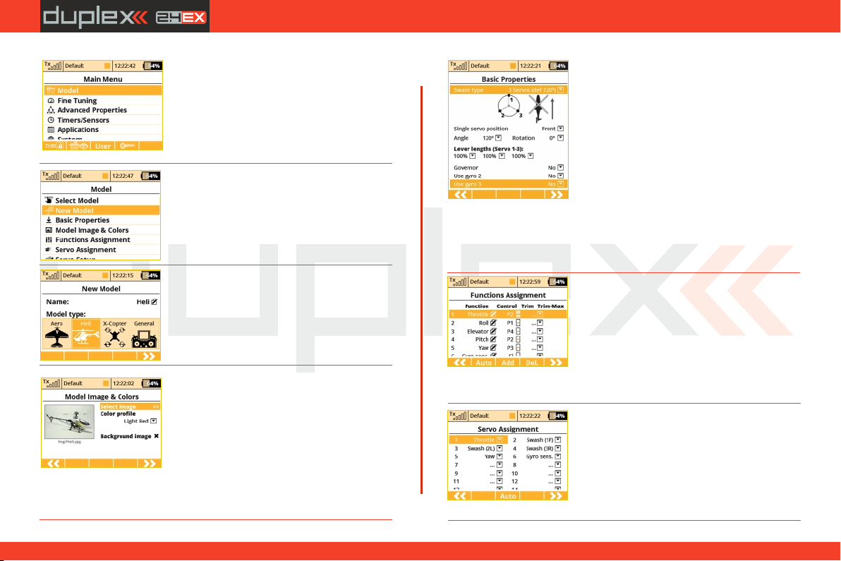
5. Select the helicopter swash plate type"3
servos (def 120°)“. Change the second
menu item "Position of front servo“ to
"Rear“ – the swash plate servo orientation
will be turned 180°. Confirm the change by
pressing the "F5(Next)” button.
button. When you create a new helicopter
model, you are required to define the
swash plate configuration for the model.
Please refer to your helicopter’s instructions and verify that you have
the correct swash plate configuation. If you find that you need to
change your swash plate configuration, you can always go to the
"Model -> Basic Properties“ menu to make the change.
6. The"Functions Assignment“ menu lists
the flight functions and their control
switch/stick assignments. If you want to
change any of the switch/stick assignments,
select the "Control“ item for your flight
function and then select your desired
switch/stick for that flight function. Press
"F5(Next)“ to confirm.
7. The „Servo assignment“ menu displays
the receiver channels and their transmitter
output assignments. If you want to change
any of the output assignments, select the
channel you want to edit and reassign its
output. Otherways press „F5(Next)“ to
confirm.
35
3.3.
Page 36
computer radio control system
EN
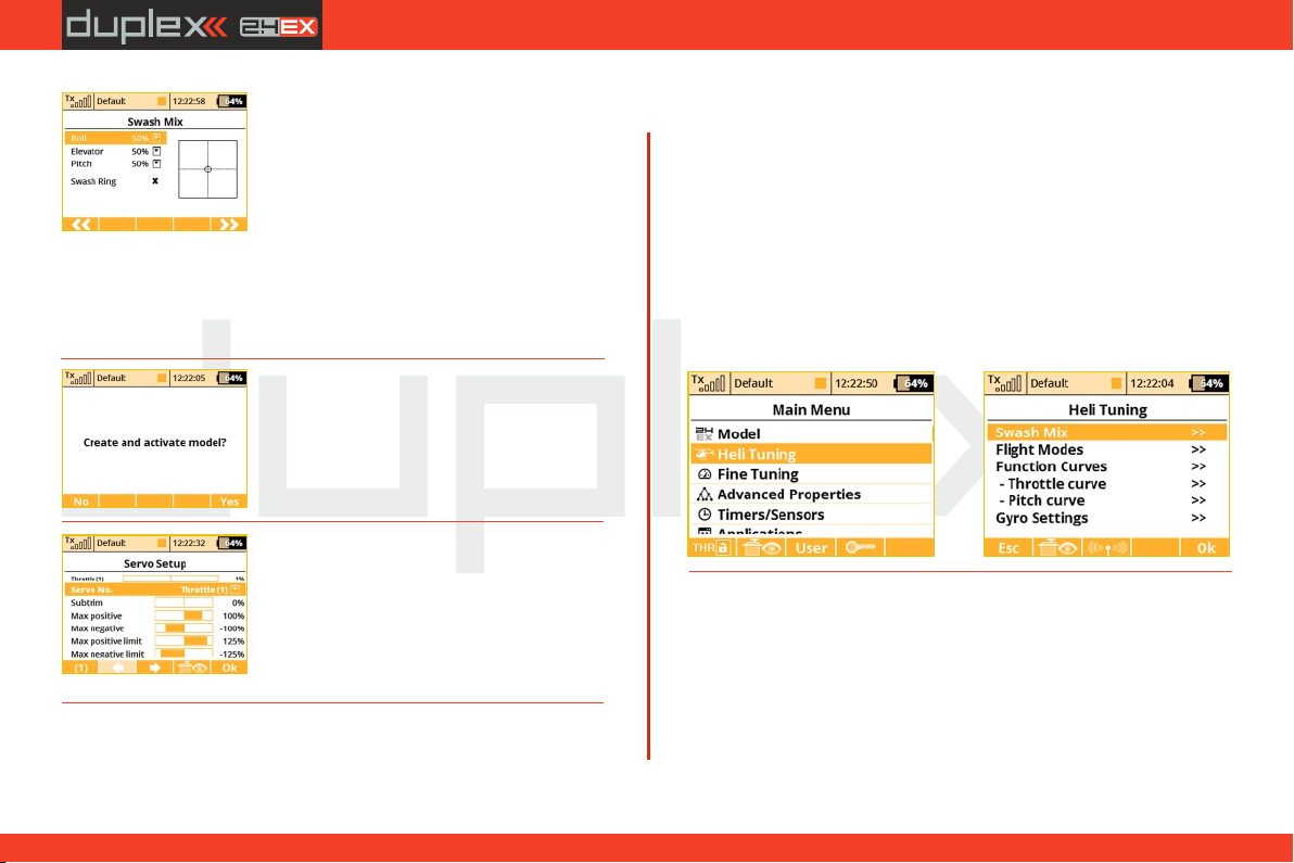
8. The "Swash Mix“ menu displays the travel
range of each particular helicopter flight
function for the swash plate for flybarred
helicopters. The travel range is displayed as a
percentage. You can use these travel range
adjustments to prevent linkage binding and
to tune the helicopter to suit your flying
style. You can also activate a cyclic reduction of the rotor head travels
(Swash Ring) so the servos cannot be damaged by large simultaneous
movements of the sticks.(Refer to your helicopter’s instruction
manual.) Press the "F5(Next)“ button to confirm.
9. The screen will display a question which
asks if you really want to create and activate
the new model. Press the"F5(Yes)“ button
to confirm.
10. The "Servo Setup“ menu is where you
can set all of your servo neutral positions,
servo output throw limits, servo reversing,
delay etc. You should return to this menu
after you have bound your receiver and
transmitter. See chapter 8.3: Receiver-
>Binding.
11. Once your transmitter has been bound with a receiver and has
been connected to its power supply, the last step consists of tuning
the servo output functions, see chapter 7.3.5: Setup of receiver
outputs.
In the "Fine tuning -> Flight modes“ menu you will setup these
advanced model control functions for your helicopter:
Collective pitch curve, see: Fine tuning -> Flight Modes->Function
Curves
Throttle curve, see: Fine tuning -> Flight Modes->Function Curves
Dual rates, see: Fine tuning -> Dual Rate/Expo
Autorotation, see: Fine tuning -> Flight Modes
Gyro/Governor see: Fine tuning -> Gyro/Governor
For convenience, a quick link to all of these function settings has been
made through the Heli Tuning menu.
7.3.3 Multicopter
The DS-12 transmitters allow you to simply create a multicopter
model equipped with gear and camera gimbal. By default, after the
creation of a multicopter model, the digital trims are disabled.
36
3.3.
Page 37
computer radio control system
EN
Servo assignment to receiver channels:
1. Throttle
2. Roll (ailerons)
3. Pitch (elevator)
4. Yaw (rudder)
5. Mode (multicopter mode channel)
Before you begin creating a model, make sure that you have setup
the correct transmitter mode in „Main menu -> System ->
Configuration -> MODE 1-4“. The basic, standardized, assignment
of transmitter inputs to flight controls are based upon this selection.
First it is necessary to create a model in the transmitter and then bind
the DS-12 transmitter with the receiver which will control the given
model. See chapter 8.3: „Receiver->Binding”
Note:
For safety reasons we strongly recommend removing the
propellers when working with a multicopter model.
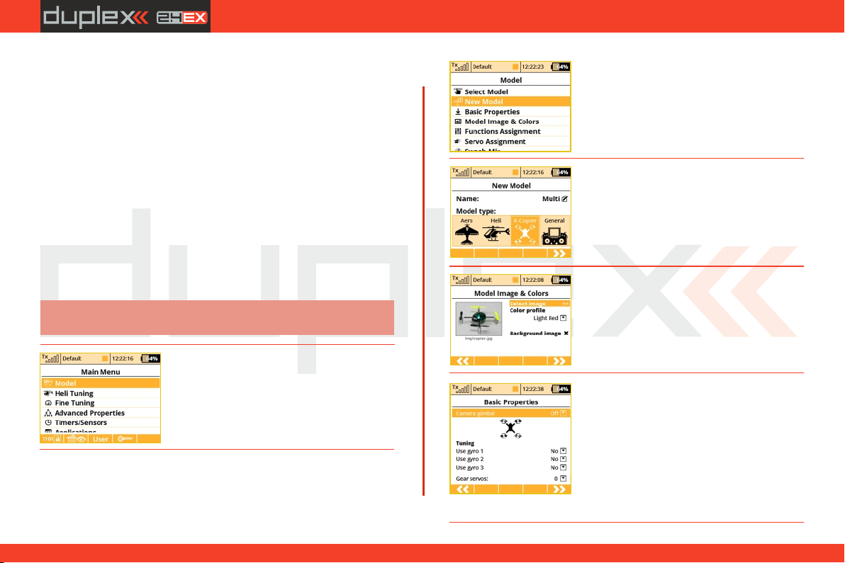
1. Switch-on the transmitter. In the main
display push the key „menu“. Select the
item „Model“ and push the „3D button“.
2. Select the item „New model“ and push
the „3D button“.
3. Enter the name of your model and press
„F5(OK)“ (Note: you must enter a model
name to proceed.) Then select the model
type „X-Copter“. Confirm by pushing the
„F5(Next)“ button.
4. Choose an optional model image and
color profile according to your personal
preferences. The images must be loaded to
the internal SD card before you use them.
You can skip this step by pressing „F5
(Next)“ button.
5. Select the basic properties of your
multicopter, i.e. type of camera gimbal (off,
two axes or three axes), number of gyro
tuning functions and gear servos.
37
3.3.
Page 38
computer radio control system
EN
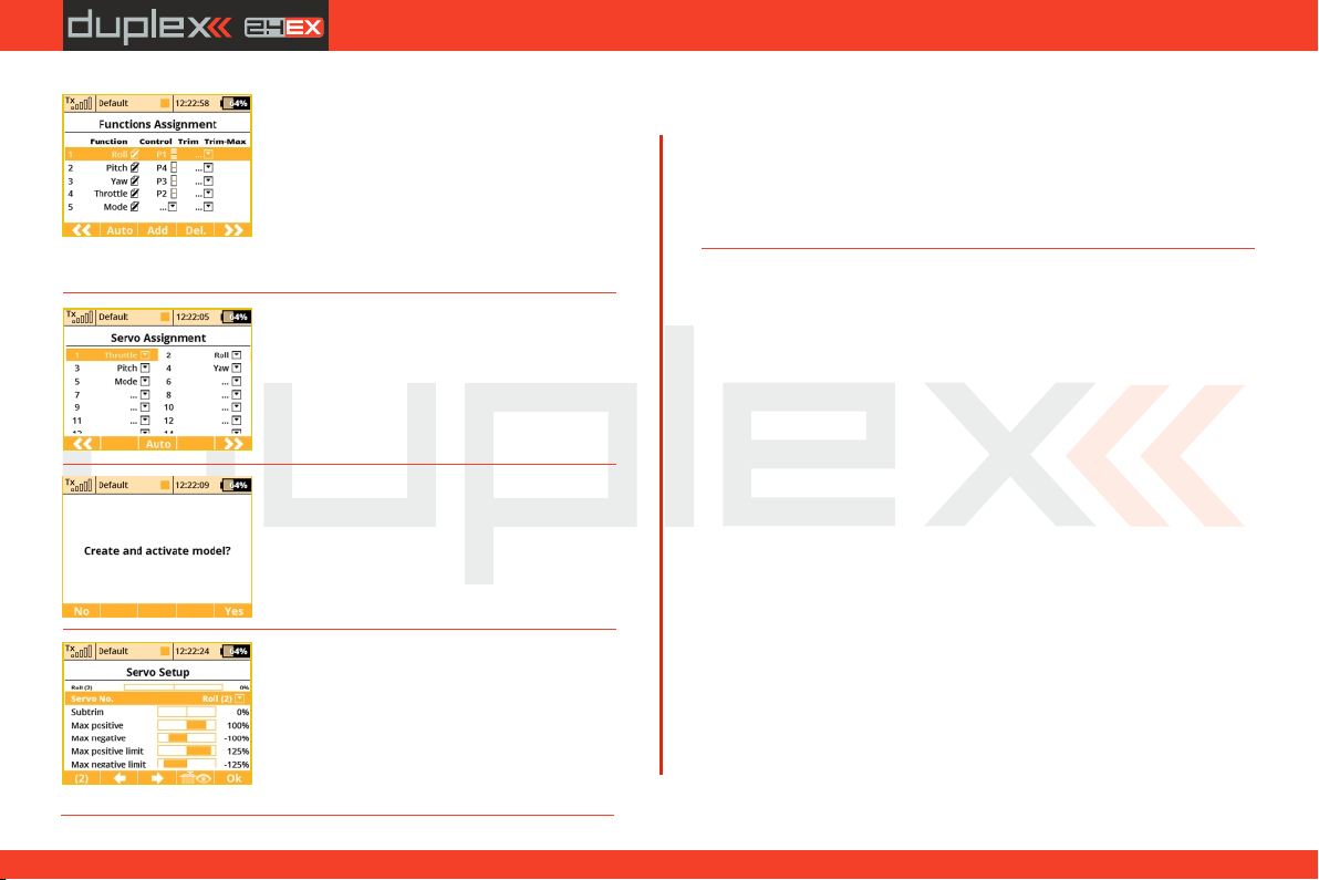
6. This page displays the flight control
functions and their transmitter switch
assignments. Here you can verify that your
flight control functions are correctly
assigned to the transmitter switches/sticks.
If they are not, check and make sure that
you have selected the proper transmitter mode. Confirm the
assignments by pushing the „F5(Next)“ button.
7. This page displays the assignment of
functions to your receiver outputs (servos).
You may change the assignments by
editing the output assignment for each
receiver channel. Otherways confirm with
the „F5(Next)“ button.
8. The screen will now display a request
which asks if you really want to create and
activate the new model. Confirm with the
„F5(Yes)“ button.
9. The Servo Setup menu is where you set
the servo neutral positions, servo output
travel limits, servo reversing, delay etc. You
will come back to this menu after binding
the receiver with your transmitter. Press the
„F5(OK)“ button and you are taken to the
main screen where your new model is displayed in a desktop page.
10. Bind transmitter with the receiver, see chapter 8.3 Receiver-
>Binding. Once your transmitter has been bound with the receiver
and you have re-applied power to the receiver, the last setup phase is
the tuning of your flight controller channels, see chapter 7.3.5
Setup of receiver outputs. Set the correct subtrims and endpoints,
so that the flight controller unit recognizes the channels as valid.
7.3.4 General
The DS-12 transmitters are not only equipped with the assistants for
airplanes or helicopters, but they also have a „General“ assistant
which can be used to create just about any other type of model. If
your model cannot be assigned to the category of an airplane or
helicopter, select the general model. The following setup describes
the creation of a boat model. This process could also be used to
create a profile for any other land/water/air model craft. In this
example, the model is controlled by basic functions like throttle and
rudder as well as by extended functions like a motor sound
generator, lighting system, siren, and a smoke generator. The first
three above mentioned functions are controlled proportionally and
the rest are non proportional.
Servo assignment to receiver channels:
1. Motor
2. Rudder
3. Motor Sound Module
4. Lighting System
5. Siren Sound Module
6. Smoke Module
38
3.3.
Page 39
computer radio control system
EN
Before creating a model, make sure that you have setup the correct
transmitter mode in "Main menu -> System -> Configuration ->
MODE 1-4“. The basic, standardized, assignment of transmitter
inputs to flight controls are based upon this selection. First it is
necessary to create a model in the transmitter and then bind the DS12 transmitter with the receiver which will control the given model,
see chapter 8.3: “Receiver->Binding”.
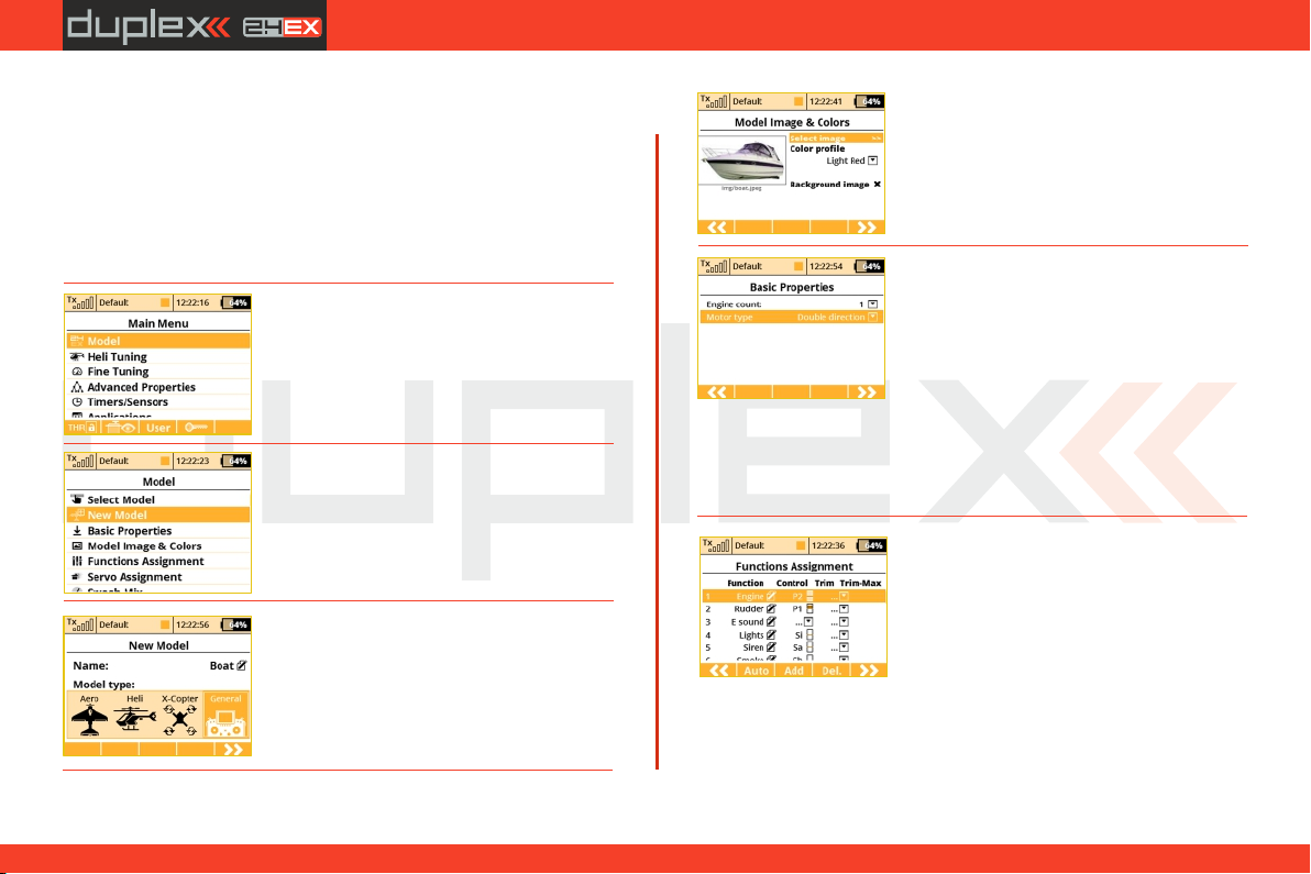
1. Switch-on the transmitter. In the main
display push the key „menu“. Select the
item „Model“ and push the „3D button“.
2. Select the item „New model“ and push
the „3D button“.
3. Enter the name of your model and press
„F5(OK)“ (Note: you must enter a model
name to proceed.) Then select the model
type „General“. Confirm by pushing the
„F5(Next)“ button.
4. Choose an optional model image and
color profile according to your personal
preferences. The images must be loaded to
the internal SD card before you use
them.You can skip this step by pressing "F5
(Next)" button.
5. The first item in the "Basic Properties“
menu is the number of motors in the
model. In this example, this item will not be
edited and we will proceed to the second
item, which is how the motor needs to be
controlled – i.e. whether the motor turns
only one direction (Single) or both
directions (Double). Edit the item "Motor
type“ by selecting "Double direction“.
Press the "F5(Next)“ button to confirm.
6. In the "Function Assignment“ menu
use the "F3(Add)“ button to create all of
your desired functions. Then you can assign
transmitter control switches/sticks to the
functions by editing each function’s
"Control“ item, see chapter: "Select
control input“. The only exception is the motor sound module
function, which you cannot simply assign to a control switch/stick,
because it wil be controlled by a mixer. The mixer will allow the
motor sound will be played proportionally to the motor speed. For
the siren function you may take advantage of the switch "Sa“
39
3.3.
Page 40
computer radio control system
EN
(spring-loaded switch). After you create all of your desired functions,
press the „F5(Next)“ button to confirm.
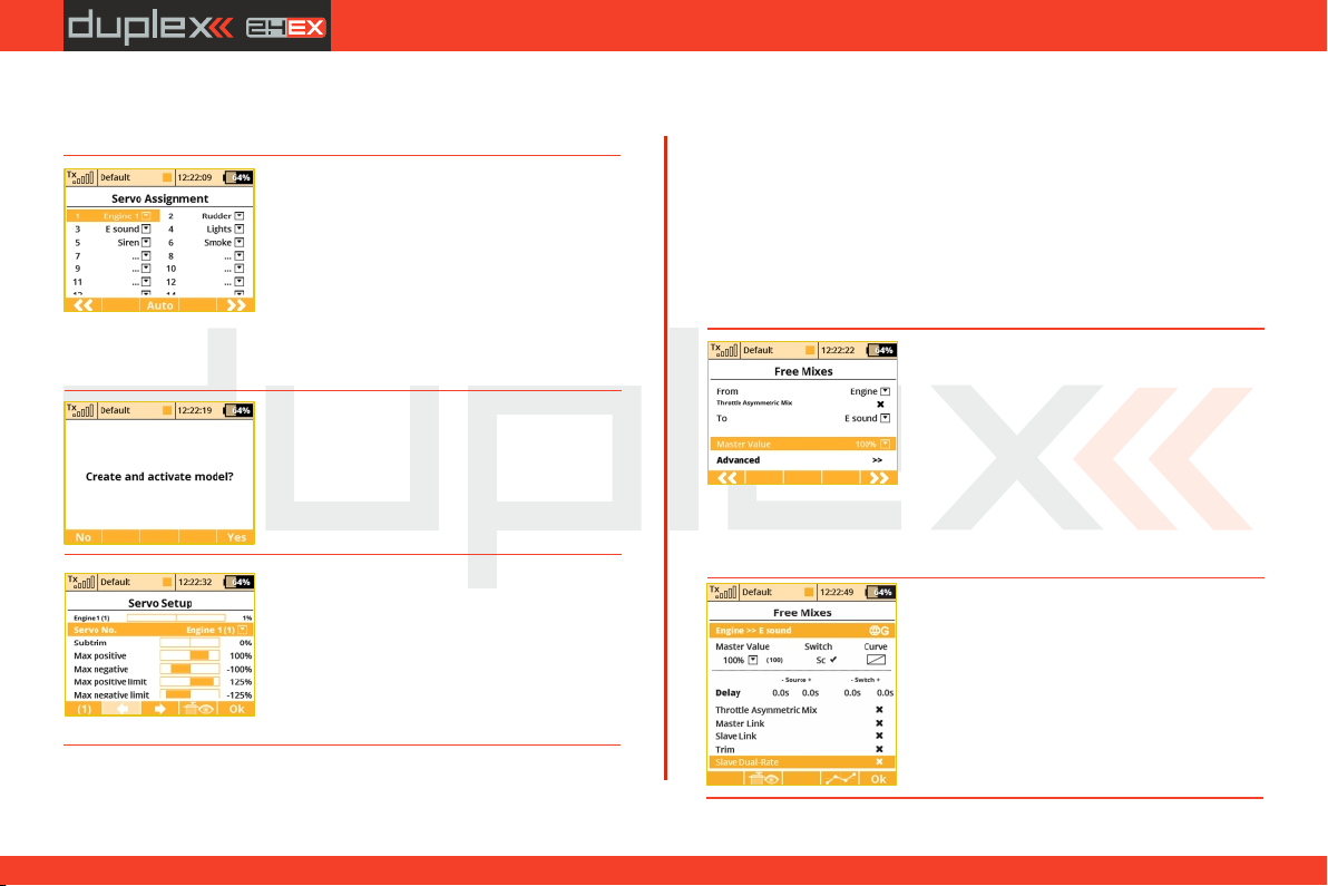
7. The "Servo assignment“ menu displays
the receiver channels and their transmitter
output assignments. The channels are
assigned in the order that you created the
functions in the previous menu. If you want
to change any of the output assignments,
select the channel you want to edit and
reassign its output. Otherways press
"F5(Next)“ to confirm.
8. The screen will display a question which
asks if you really want to create and activate
the new model. Press the „F5(Yes)“ button
to confirm.
9. The "Servo Setup“ menu is where you
can set all of your servo neutral positions,
servo output throw limits, servo reversing,
delay etc. You should return to this menu
after you have bound your receiver and
transmitter. See the chapter 8.3: Receiver-
>Binding.
Once your transmitter has been bound with a receiver and has been
connected to its power supply, the last step consists of tuning the
servo output functions, see chapter 7.3.5: Setup of receiver
outputs.
To complete this model we just need to configure a free mixer from
the throttle function to the motor sound module. In this example we
will set a switch to enable/disable the mixer so that when the switch
is "on“, the motor sound module is controlled with the throttle
(motor speed). Go to the "Fine tuning->Free mixers“ menu.
a. Use the „F2(Add)“ button to create a
new mixer. Select „Engine“ in the „From“
item. Then select „Sound M“ (the name of
the sound function) in the „To“ item. The
item „Master Value“ represents the
amount of mixing from the input function
to the output function for this mixer. With the „F5(Next)“ button you
will create the mixer and the display will change to show the
overview of your programmed free mixers.
b. To assign a switch for the activation and
deactivation of the free mixer, press the
"F4(Edit)“ button. Select and edit the
"Switch“ item to assign a switch/stick to
enable/disable the mixer.
40
3.3.
Page 41
computer radio control system
EN
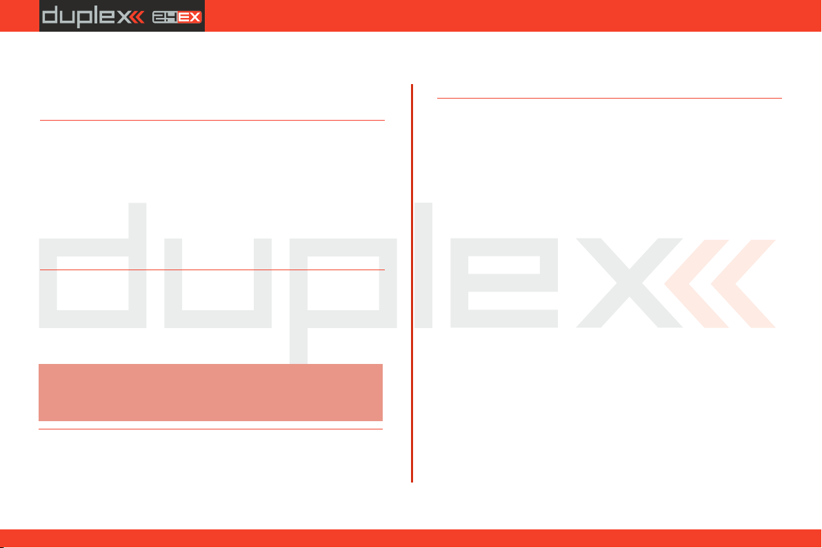
7.3.5 setup of Receiver Outputs
Go to the "Model->Servo Setup“ menu. Use the "F2“ and "F3“
buttons to brows through the receiver outputs (channels).
You can scrol through the following servo adjustment items for each
channel:
„Servo reversing“ – reverses the servo throw direction.
Move the stick for your selected channel and observe the direction
of the servo movement. If the servo moves in the opposite of your
desired direction, change the direction by editing the „Reverse“ item
for that particular servo. Continue with each channel until all of
theservos travel in the required directions.
„Center (Subtrim)“- adjusts the center position of each servo’s
output.
With your sticks in their neutral positions, scroll through each servo’s
page and use the "Center (Subtrim)“ item to correctly set all of your
servo‘s center or neutral positions.
Note:
You should mechanically adjust all of your servo arms and servo
linkages to be as close to neutral or center as possible so that you
will need as little subtrim as possible. Using large amounts of
subtrim can limit the overall throw of your servo.
„Max/Min. limit“ – sets the absolute maximum servo output throw
their full travel. You should use the dual rate function to set your
model’s useable control throws.
Use these to limit the maximum range of servo throw in order to
keep your servos from exceeding their mechanical limits or to keep
your servos from binding when moving their arms or linkages to
41
3.3.
Page 42
computer radio control system
EN
8 Receiver
8.1 Description
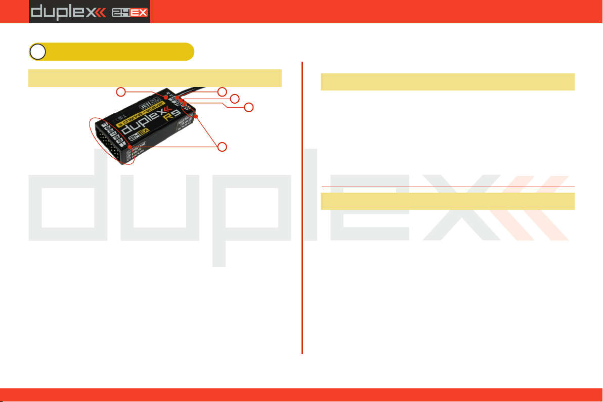
5 4
1. JETI Duplex receivers use the universal or „JR Type“ servo
connectors.
2. Bat - receiver and servo power supply input. Whenever
possible, always supply power to your receiver using more than one
of these inputs. You can either supply power through the use of a
Ycable or through any unused receiver channel connection. To
power the receiver you may use NiCd packs, the BEC from your ESC or
Li-xx cells used with a voltage regulator, such as the JETI MAXBEC or
similar.
3. SAT - auxillary input/output for PPM signals. This input allows
you to connect an additional JETI DUPLEX Rsat2 satellite receiver or
an additional US version Duplex receiver.This allows you to increase
the number of receiver antennas in your system for increased
reliabilty in installations with shielded or badly oriented antennas.
4. EXT - input for telemetry sensors. If you want to connect more
than one telemetry sensor then use the JETI EXPANDER E4. You can
„daisy-chain“ several of the E4 Expanders to support many, many
sensors.
3
2
1
5. A1/A2 - receiver antennas. The antennas should be installed
so that the wires form a 90° angle relative to each other.
8.2 Installation
Whenever possible, you should wrap the receiver in foam and place
it as far as possible from sources of interference (servos, electric
motors). Arrange the receiver antennas so that their active ends
forem a 90° angle and try to put them as far as possible away from
each other. Take care not to bend them with a radius smaller than 1
cm. The active part of the antenna should not be placed close to
metal parts. If your model has a carbon fuselage it is very important
to place the active antenna ends outside the fuselage.
8.3 Binding
In order to achieve communication between transmitter and
receiver you must bind them. During this process the transmitter
learns the receiver address and will automatically find it again when
switched back on. Communication begins with this receiver
automatically if the transmitter is not already communicating with
another receiver. The binding process needs only to be done once
for each receiver.
8.3.1 Standard pairing procedure
1. Switch off the transmitter and receiver.
2. Plug the „BIND PLUG“ into the EXT receiver input.
3. Connect receiver power supply.
4. Switch on the transmitter. The receiver will bind with the
primary transmitter module.
42
3.3.
Page 43
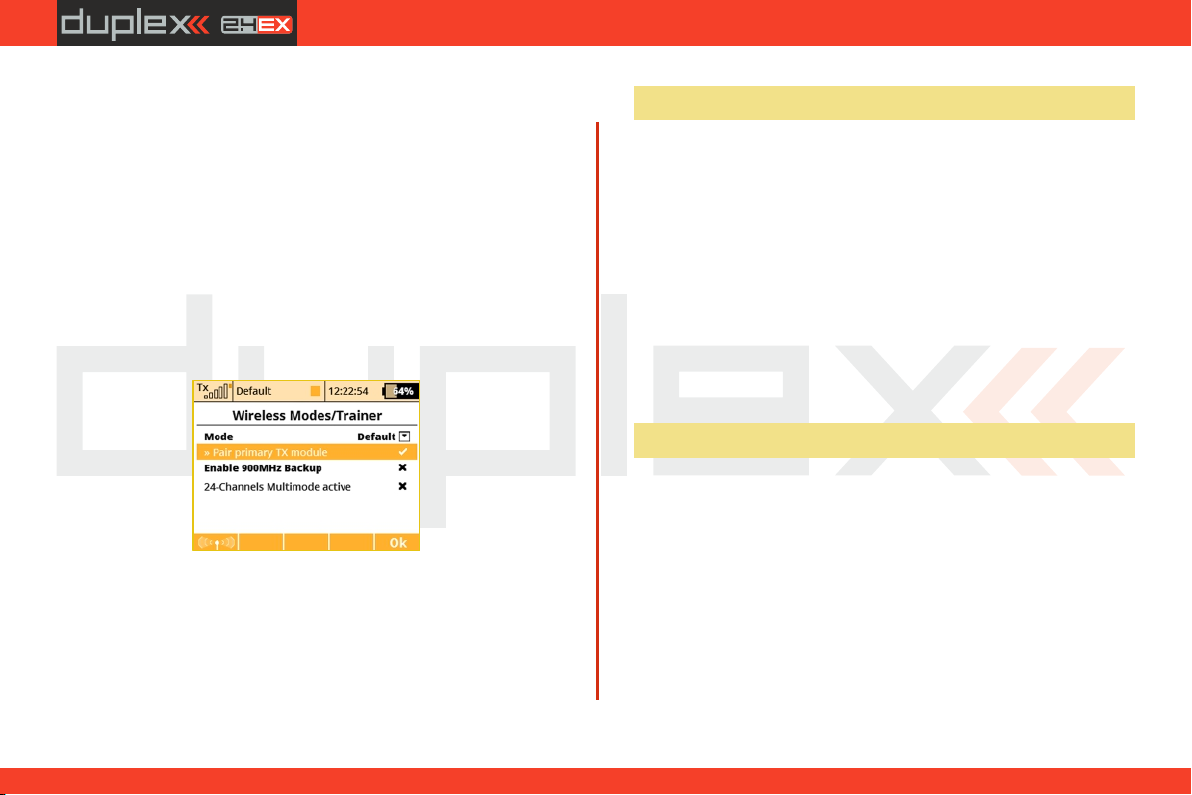
computer radio control system
EN
8.3.2 Alternative pairing procedure through the
transmitter menu
1. Turn off the receiver. Keep the transmitter turned on.
2. Plug the "BIND PLUG" into the EXT receiver input.
3. Connect receiver power supply.
4. Locate the transmitter menu „Advanced Properties -> Wireless
Modes/Trainer”
5. Highlight "Pair primary TX module" and press the „3D button”.
6. The receiver will bind with the transmitter. Confirm the registered
device.
8.4 Range Test
The range test will verify that the transmitter and receiver are
functioning properly.
Before the first flight of each flying session or if have any doubts
about the transmitter or receiver function, you should always check
the range. During the range test the transmitter’s output power is
decreased to 10%.
When performing a range test, both the model and the transmitter
should be at a minimum height of 80 cm (31.5“) above the ground. A
correctly functioning transmitter and receiver in range test mode
should safely control a model to a minimum distance of 50m (164‘). If
not, check your model’s antenna installation first. If the test is still not
successful, don´t fly the equipment and contact your retail shop or
one of the JETI authorized service centers.
8.5 Fail safe
All Duplex 2.4GHz system receivers are equipped with "fail safe“, a
function which reacts to control signal transmission interruptions.
When your receiver for any reason does not receive transmitter
information, it changes, after a pre-set time period, to one of the
following modes.
„Repeat“ – This mode holds the last valid control throw signal ( this is
the default mode for all receivers)
„Out off“ – There is no output signal provided by the receiver, i. e.
servos do not keep their positions
„Failsafe“ – receiver outputs change to preset positions
43
3.3.
Page 44

computer radio control system
Each receiver channel can be configured to one of the modes
described above. We recommend that you setup "fail safe“ positions
for every output, which enables your model to stay in a stable
condition. For instance, the elevator and rudder in neutral positions,
electric motor switched-off, gas engine idling, spoilers extended.
Configuration Method of the receiver failsafe function.
1. Bind receiver with transmitter. See chapter: 8.3 Binding. Leave
receiver and transmitter in switched-on condition.
2. In the transmitter, go to the menu „Applications -> Jetibox“
and proceed according to picture. Use the F1-F4 function buttons
to move within the menu.
3. In the „Set Output Pin“ menu select the receiver output which
you want to configure (use the left/right buttons) and proceed (by
using the down-button).
4. In the "Signal Fault Yn“ menu where n denotes the channel
number which has to be configured, use the right-button to edit the
output function showing a signal failure (setup "fail safe“). You have
now activated the "fail safe“ function on receiver channel output n.
5. The "fail safe“ is adjusted by pressing the down-button and
changing to the „fail safe“ menu. With the left/right buttons edit the
"fail safe“ value in a range of 0.8ms to 2.2 ms. Adjust all of the
connected receiver outputs by repeating steps 3-5.
The last parameter to be set up is the elapsed time after signal failure
when the "fail safe“ or other actions after signal failure will be
initiated. In the "SignalFault Delay“ menu you can define the length
of time after a signal fault occurrs in which the preset throws are
applied. The values in this menu are changed by pressing the
left/right buttons.
EN
44
3.3.
Page 45
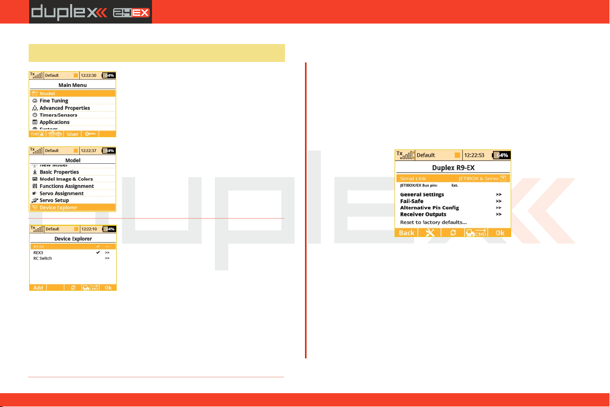
computer radio control system
EN
8.6 Using Device Explorer To Configure the Receiver
The Device Explorer utilizes the latest
data/ command E X Bus protocol to
wirelessly configure remote devices such as
receivers, sensors and other EX Bus
compatible devices. You can check the
label of your device to see if it supports the
EX Bus protocol.
Basically, the Device Explorer (located in
the Model menu) replaces the integrated
JETIBOX emulation and brings additional,
more intelligent ways to communicate
with your remote devices. The main Device
Explorer window shows a list of available
devices. The recognized devices are labeled with their registered
name, others are not displayed or only displayed as a device ID. The
check mark tells you that the device is ready and that you can
configure it. By using the "F3" Refresh button you can reset the
displayed devices, this forces the auto-detection function to explore
all attached devices. The remote sensor and device detection
process is always running in the background.
In the picture above, two receivers have been detected and are
recognized. When you press the rotary button, you are able to
configure them in detail. Here is the example how to use the Device
Explorer to configure an "R9 EX"receiver:
First, the transmitter downloads all settings from the receiver. After
that operation is completed you should be able to see the basic
configuration of the receiver as shown in the picture . Every a)
modification that you make is automatically uploaded back to the
receiver, so that you can immediately see results of the steps you are
a)
doing and there is no need to continuously "save" your changes. For
your convenience, there is a "Refresh" button "F3", which causes all
of the data to be downloaded from the receiver once again. This is
beneficial mainly if you are modifying the configuration by using a
JETIBOX device and the Device Explorer simultaneously.
The "F2" Tools button is used to enter a special dialog where you can
import and export settings of the particular device. If you want to
export the configuration of your (for example) receiver, just enter the
"Export settings" menu item, set the file name and confirm.
Similarly you can import this configuration to the device. All the
exported files are stored in the "Export" folder on the SD card.
45
3.3.
Page 46
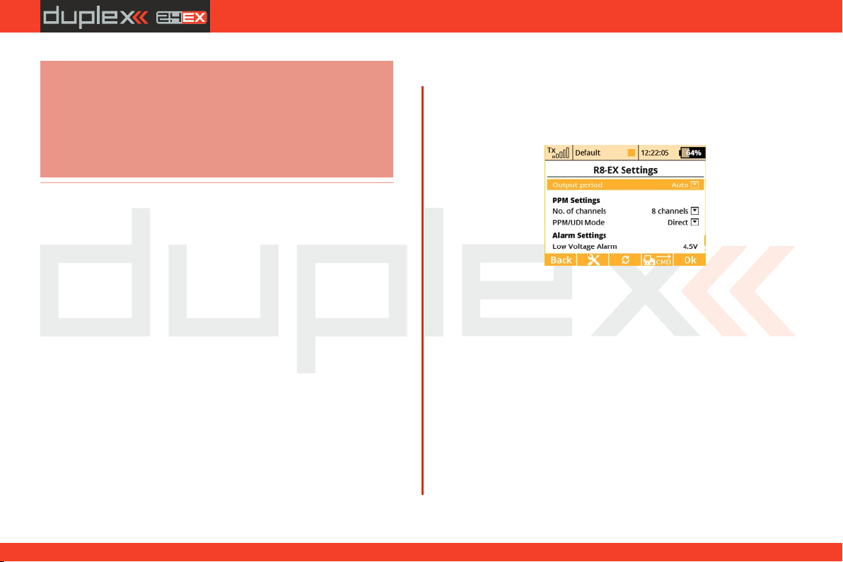
computer radio control system
EN
Note:
Before a device can be recognized, a special predefined
configuration scheme must be present on the SD card in the
/Devices folder. If the scheme doesn't match or doesn't exist, an
error message "Unknown device" is displayed. If such an error
occurs, please download the latest software for your DS-12
which, by default, has all the definitions included, or contact your
dealer for assistance. This text describes properties introduced in
receiver version 3.20.
The picture shows the following adjustable parameters:a)
- Serial Link – This determines the operational mode of the
receiver. You can choose from these options:
• JETIBOX & Servo– The standard mode for directservo control.
• PPM Positive, PPM negative – the servo signal is summed into
a standard or inversed PPM signal. This option is for devices
which can use single line servo output data. Direct connection of
servos in this mode is supported as well.
• EX Bus – Tells the receiver that it should send all data onto a fast
digital serial link for further processing. This is the recommended
option if you are connecting the receiver to the Central Box or
another EX Bus intelligent device.
• UDI - Universal Data Interface. - This is a unidirectional digital
serial protocol that can transmit up to 12 channels on a single
wire. The UDI is compatible with several stabilization systems for
helicopters and airplanes.
-General Settings - redirects you to screen b)
- Fail-Safe - redirects you to screen c)
- Alternative Pin Config - redirects you to screen d)
- Receiver Outputs - redirects you to screen e)
- Reset to factory defaults... – After confirmation, the receiver's
configuration will be restored to its factory settings.
The next page (General Settings) shows basic properties of the
receiver (picture . b)
b)
- Output Period – Determines how often the servo signal will
be repeated to the outputs of the receiver. You can select periods
from 5ms to 30ms (in 5ms steps). Recommended option:
„Auto”.
PPM Settings
- Number of channels – if the output mode selected is either
positive or negative PPM, you can set how many channels will show
on the output.
- SAT1/SAT2 - Some types of receivers support input of backup PPM
signal. This signal can be captured via SAT1 or SAT2 ports. Here you
can define the mode of operation for the particular ports. The PPM
input can be accepted only in standard servo mode and EX Bus
mode. Additionally, the SAT2 port can be configured as a PPM
output. In this case the SAT2 outputs all 16 channels if not specified
otherwise.
46
3.3.
Page 47
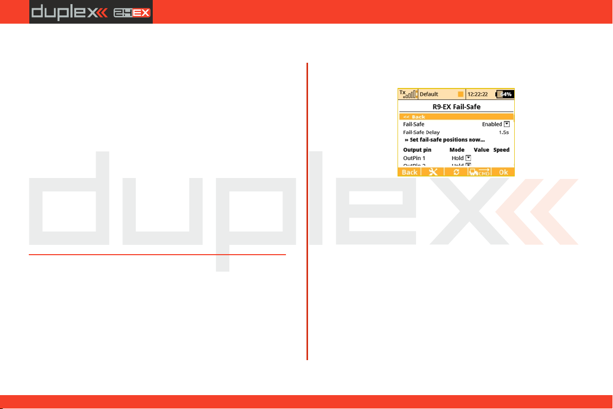
computer radio control system
EN
- PPM/UDI Mode - determines processing and additional logic
applied to the PPM and UDI protocols.
- Direct - signals received from the transmitter are not further on
processed in the receiver, they are generated without any change at
the output of the receiver in form of PPM/digital signals. If a signal
loss occurs, no PPM/digital data will be generated by the receiver.
- Computed - the signals received from the transmitter can be
processed further on in the receiver and its menus "Channel set" and
"Out Pin Set" programmable channel outputs, gains etc.)
Alarm Settings
- Low Voltage Alarm - the value serves for the setup of the alert
decision threshold. As soon as during operation the actual voltage
decreases below the set threshold, the receiver will generate an
alarm. The transmitter may announce this situation by an acoustic
tone (this depends on transmitter alarm settings, please refer to
chapter describing "Timers/Sensors -> Alarms”).
On the next page (picture ) shows the fail-safe function c)
parameters.
- Fail-Safe – This parameter tells the receiver how to react when a
signal loss event occurs. If you set “Enabled" then you will be able to
set the behavior of every channel independently. The “Disabled"
option says that if no signal is being received from the transmitter, no
driving signal for the servos (or PPM) will be present.
- Fail-Safe Delay – The number of seconds that must elapse from the
moment of losing signal until the fail-safe is activated. This option is
available only if the Individual mode is selected.
- Each output position of the receiver has three adjustable
parameters:
c)
Mode (Hold, Out OFF or Fail-Safe) – Dictates, how the specific •
output behaves if a signal loss occurs. Using the Hold mode, the
latest known servo position will be held. Out Off option means that
there will be no signal to the particular servo channel. The last
option, Fail-Safe, will set the servo to (user) predefined position (set
in the "Value" column).
Value – The position of the servo after a signal loss occurs. This is •
available only when the Fail-Safe mode is selected. For convenience,
you can press the "F4 Apply” button while you are editing this
column. The selected value will then appear directly on the servo
output without the need to turn off the RF modules which would
eventually activate the fail-safe and show the set position. The
“Apply” function makes it faster to set your fail- safe positions.
Slope – This slows down the speed of servo movement while the •
output is moving from the normal position to the fail-safe
position.
47
3.3.
Page 48
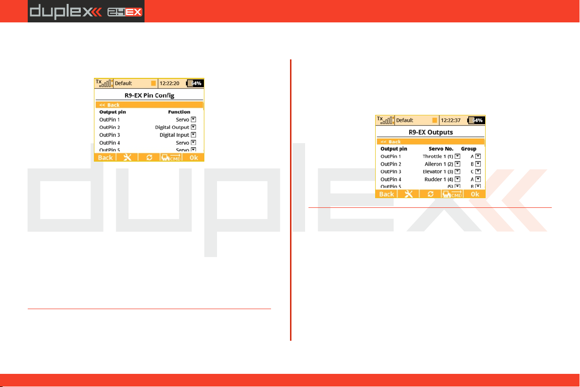
computer radio control system
EN
The screen , "Alternative Pin Config", allows you to modify the d)
modes of receiver output pins. The servo outputs can be configured
into Digital input and Digital output modes.
d)
- Digital input mode: a logical value of a given signal pin (0 or 1 as a
result) is transmitted to the DS-12 in form of EX telemetry so that it
can be further on processed (displayed and stored to the SD card).
The receiver pins are equipped with internal pull-up resistors. To
detect logical value of a given pin it is enough to connect the signal
pin with the ground.
- Digital output mode: The channel value of a given output pin is
discretized into two values. If the channel value is greater than
1.5ms, the pin output will be log.1. Otherwise the signal pin will stay
at logical 0. Using this way you can simply control for example lights
consisting of several LEDs. The fail-safe configuration is applied in
this mode as well as in servo mode.
The page Receiver Outputs (picture )) allows you to redirect your e
transmitter’s channels to any output of the receiver. For convenience
the transmitter’s channel numbers are displayed together with the
appropriate function names, making it easier to adjust. In addition,
you can also set the servo group for each channel. For more
information please refer to your receiver manual.
e)
8.6.1 Support of remote commands for EX Bus devices
The DS-12 transmitters support up to 16 universal commands for
wirelessly connected devices supporting EX Bus. To view the list of
active commands, press the "F4” CMD button when in the "Model ->
Device Explorer” menu. However, the command must be detected
before it can be activated. As an example of the use of wireless
commands, the Central Box can be used and its command that resets
the minimum, maximum values and battery capacity (Clear MIN /
MAX values).
48
3.3.
Page 49
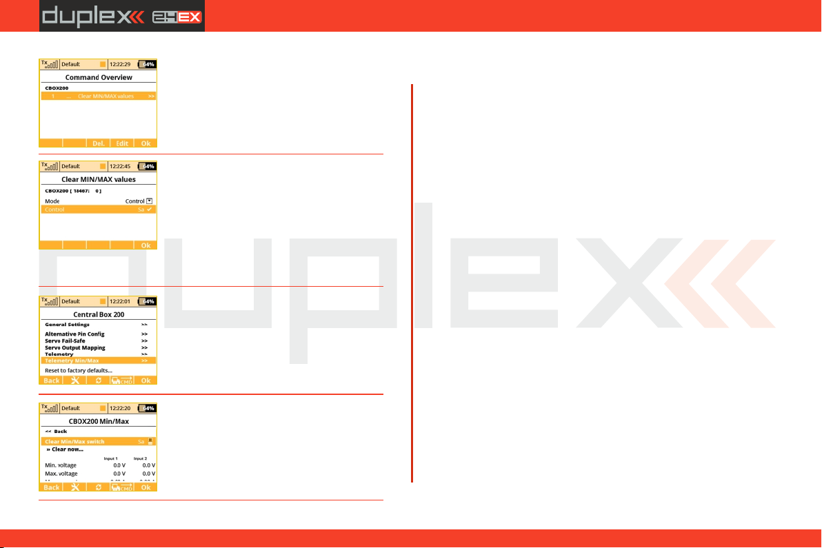
computer radio control system
EN
1. The list of active commands.
2. Sa s w i t c h i s a s s i g n e d t o reset
minimums, maximums, and the measured
capacity. For the reset command only the
Control mode is available (the position of
the control/switch is taken as an input),
other devices may accept a proportional
value specified as a constant or as the
channel number on the transmitter.
3. Scroll to view minimums and maximums.
4. Pushing the „3D” button enables you to
add the command into the list of active
commands and it is possible to assign a
transmitter control to it.
On the main screen of the Central Box settings scroll down to display
the maximum telemetry values (Telemetry Min/Max). Here you will
find a choice to assign a switch to the command for deleting
measured minimums and maximums (Clear Min/Max switch).
Pushing the "3D” button on this item you are moved to the list of
active commands where this command is already listed and is
inversely highlighted with a cursor.
Pushing the "3D” button moves you to the choice to assign the
control/switch that will further on take care of the command for
resetting. Here we have chosen the Sa switch.
Further operation of the command will look like this:
- Moving the Sa switch into the ON position makes the transmitter
detect that it should send the command for resetting telemetry
minimums and maximums to the model. However, before the
command is applied, it is necessary to confirm the choice by the pilot
to avoid unwanted resetting of the data.
- The transmitter displays a dialog asking if you want to execute the
command for resetting the telemetry. If you press NO or you do not
manage to respond in time, the dialog closes and the command is
not executed.
- Conversely, if you press YES, the command is sent to the model
where it is processed by the Central Box which resets its telemetry.
The result of this command can be displayed on the main screen of
the transmitter in the telemetry window – the item Capacity of the
Central Box will now be set to zero.
49
3.3.
Page 50
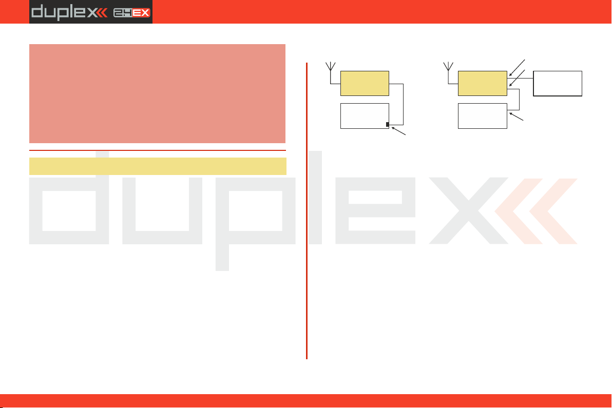
computer radio control system
EN
Note:
This text describes receiver properties introduced in DS12 V3.0 and receivers version 3.25. Earlier versions of the
firmware might offer different properties, or the
described configuration might be entirely inaccessible.
Receiver software is updated through a PC with the aid of
the JETI USBa adapter. For more details refer to the USBa
adapter manual.
8.7 R C-Switch
The RC Switch is a special wireless device that allows you to remotely
connect or disconnect the receiver power supply of your model.
There are currently two variants of the device: RC Switch and RC
Power Switch. The difference is noticeable in the picture below. The
simple RC Switch is suitable for applications where a Central Box,
Max Bec 2D plus, SBEC 40 or other intelligent electronic device is
being used. It offers a single output pin that might be wirelessly
driven high or low according to the situation.
When connected in place of a magnetic key, the RC Switch can turn
the electronics in the model on and off.
The second variant, the RC Power Switch, can fully replace a standard
physical switch. It can directly drive servos and electronics since it
includes a couple of low-resistant MOSFETS. Just plug the RC Power
Switch between the battery and the receiver, configure the
switchrelated settings in your transmitter and bind it as a standard
receiver.
Variant of the RC Switch
RC Switch
Central Box
Max Bec 2Dplus
SBEC 40, etc.
Magnetic key plug
RC Power Switch
Standard receiver
Power In
Power Out
Receiver battery
Battery plug
The switch-related settings are located in Model-> Device Explorer > RC-Switch. First, you have to enable the switch by pushing the
rotary button on your transmitter with the first row of the transmitter
display highlighted.
Then you should bind the RC Switch:
• Put the bind plug into RC Switch and then turn it on.
• Push the rotary button with the "Pair RC Switch" row
highlighted on your transmitter display.
• The ID of the switch is automatically saved.
The Transmitter control switch function is a source of events:
If you want to turn the model on, then flip the assigned control
switch and confirm the question that appears. If you want to turn the
model off, just flip the switch back and also confirm the question.
You can invert polarity of the switch (if high logical level doesn’t turn
the device on) and also set the audible signals that will be activated
every time the status of RC Switch is changed (turned on or off ).
50
3.3.
Page 51
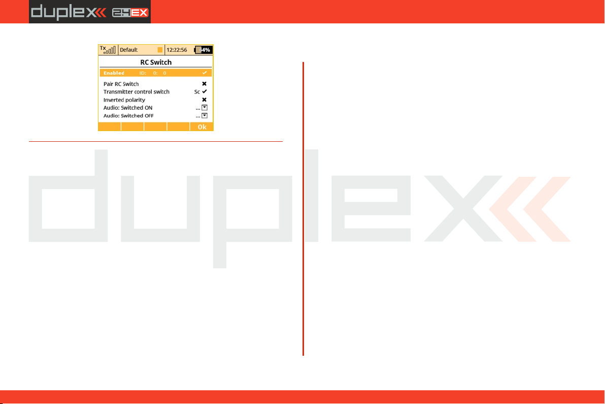
computer radio control system
EN
51
3.3.
Page 52
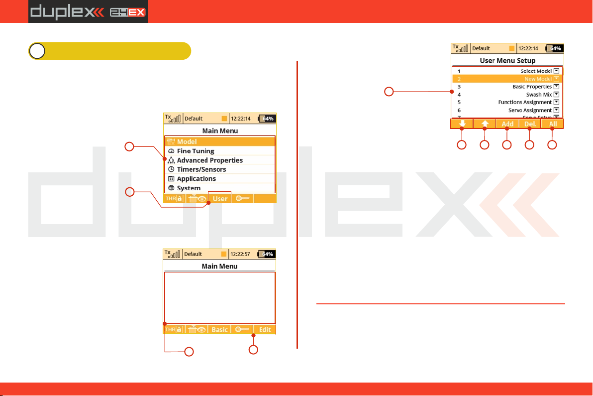
computer radio control system
EN
9 Main menu
You reach the basic menu from the main display by pressing the
„menu“ key.
1. The main menu is divided into a basic and a user section. In
the basic menu, the menu items are divided into sub-menus.
• Model
• Heli Tuning
(only for model helis)
• Fine Tuning
• Advanced Properties
• Timers/sensors
• Applications
• System
2. You enter into the user section of the main menu by pressing
the „F3(User)” button. In this section you may create a custom,
user defined menu according to your needs.
3. In t h e b a sic setup the
menu contains no items.
4. By pressing the „F5(Edit)“
button you will enter into the User
Menu Setup section.
1
2
5. The numbers on the left side
of the display shows the sequence
of the menu items.
5
7
66
6. With the „F1“ and „F2“ buttons you may change the sequence
of the selected menu items.
7. With the "F3(Add)“ you will create a new item in the user
section of the main menu. By pressing the "3D button“ when the
menu item is selected, you will change to the selection menu of that
item.
8. With the „F4(Delete)“ button you will delete the selected
menu item.
9. With the "F5(All)“ button you will insert all of the possible
submenu items into the user menu.
In both sections there are functions like throttle lock and servo
monitor which are accessible by using the "F1(THR)“ and
"F2(Receiver output)“ buttons.
98
3
4
52
4. 4.
Page 53
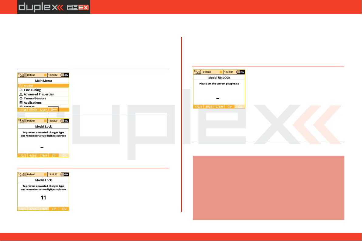
computer radio control system
EN
9.0.1 Pas sw o rd pro te ct io n a ga in st acc id en ta l
configuration changes
If you lend the transmitter to another person and you want to ensure
that no changes in the model configuration that could influence the
function of the transmitter or the model can be done, you can take
advantage of the Model Lock function.
1. In the main menu, push the „F4" button
to display the dialog for entering the onetime password.
2. Here, enter the two-digit code using the
"F1" 1/2/3, "F2" 4/5/6 and "F3" 7/8/9. This
code appears on the display and will later
be used to unlock the transmitter.
Pushing "F4” Clear enables you to delete
the specified number and you can start up
again.
3. Remember the code and push „F5" OK.
Now confirm the safety prompt “Apply
changes?”.
From now on the transmitter will be
locked against:
- changes in configuration
- selection of the model
- creating a new model
- calibration of controls
- logging telemetry
- USB connection
- switching off
All the work with the SD card therefore takes place in read-only
mode.
4. Unlocking the model is possible via the
"F4" button in the Main Menu. Now you
need to enter the same code as when
locking the model. Confirm with "OK”
button.
Now you are asked whether you want to save the changes to the
configuration of the model or not.
Pushing "F1" NO button makes all the changes discarded and all the
data from the SD card will be reloaded.
Note:
This function cannot in any case be used to increase
safety, eg. against the theft of the transmitter. The
transmitter is locked against configuration changes
from t he m oment you enter the code until the
transmitter is subsequently switched off or the code is
reentered. As soon as the transmitter is switched off, (eg.
pushing the combination of POWER+ESC or removing
the power supply), the transmitter is automatically
unlocked.
53
4. 4.
Page 54
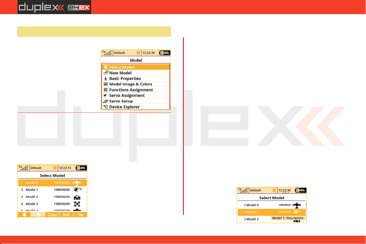
computer radio control system
EN
9.1 Model
The „Model“ menu contains basic functions for working with your
model, like:
• Select Model
• New Model
• Basic Properties
• Mosel Image & Color
• Functions Assignments
• Servo Assignment
• Servo Setup
• Device Explorer
9.1.1 Model Selection
The menu displays a list of your models stored in the memory with
their names, setup dates and model types. The currently selected
model is marked by a check mark. In the menu you may select a
model and manage all of your models. You can copy models, delete
models (except for the currently selected model) and change the
storage sequence of your models.
1. Model selection
In the list of models, select the
required model and confirm it by
pressing the "3D b utton “ or
"F1(Ok)“ button. You will be
prompted to confirm loading of the
selected model.
The DS-12 transmitters offer a
"Model checking“ function, which compares the series number of
the receiver in the model profile with the series number of the
receiver with which it is starting to communicate. If the two series
numbers do not match, the transmitter displays a warning that a
different receiver has been detected for the model. In this situation,
you the user will decide whether to:
• Confirm the change – this assigns the new receiver to the model.
• Reject the change – the transmitter will not communicate with the
newly detected receiver and model will not be switched on.
ź Select another model from the transmitter register. The
information about receiver discrepancies will also be displayed
after the creation of a new model and binding or establishing
communication with the receiver.
Through the use of this function, if you choose, the new receiver will
be assigned to the given model for future checks.
2. Model description
Model description (a "label" parameter) has been added to the
Model – Basic Properties menu. The label is then shown while you
browse the model list withinthe Model Selection menu. The label
has an informative meaning and should be used to distinguish
between similar models.
54
4. 4.
Page 55
computer radio control system
EN
3. Copying a model
The complete setup information of a model can be copied and used
to create a new model with the same programming. Select the
model from the model list that you want to copy and then create the
copy by pressing the "F3(Copy)“ button. You will need to edit the
name of your copied model before it can be saved. Once you edit
thename, press the "F5(Ok)“ button to continue. Your model copy
will appear at the end of your model list.
Note:
If you would like to make set-up changes in an existing
model, you should first make a copy of the original setup.
This will help you if you would like to return to the
original model setup.
If you would like to copy a model from one transmitter to
Note:
another you should notice that the transmitters may not
have the same software equipment, so the configuration
of activated modules may not match each other. In this
case it is necessary to check the individual functions of
the model, since an attempt to load the model file by
another transmitter may end up with an error message
(see System -> Installed Modules).
4. Deleting a Model
A model can be removed from the memory by selecting the model
you want to delete and pressing the "F5(Delete)“ button. It is
impossible to delete the currently selected model.
5. Choice of model sequence
The sequence of models can be changed by using the "F1“ button to
move the selected model one position downwards or by using the
"F2“ button to move the model one position upwards. The
transmitter allows storing of many models in the memory.
Note:
Try to arrange your most frequently used models at the
beginning of the model list in order to avoid having to
browse the whole list when selecting a model.
9.1.2 New Model
Selecting this menu item starts the new model creation assistant.
The assistant begins creating a new model profile as soon as you
select "New model“. However, the new model will only be created
after the confirmation in the last assistant menu, "Ser vo
Assignment“. Until you make the final confirmation, the new model
is NOT created or stored in the memory.
The setup possibilities of the DS-12 transmitters are very extensive.
For simplicity, some of the possible adjustments are accessible only
for certain combinations of wing and tail arrangements,
aerodynamic brakes, landing gears, and number of motors or
engines.
Note:
For safety, start creating a model with the receiver in the model
switched off. Be careful when handling electric models or servo
binding, where an improper linkage connection may cause
damage when power is applied. When handling electric models
it is safer to remove the propeller or disconnect the motor during
model creation and tuning.
55
4. 4.
Page 56
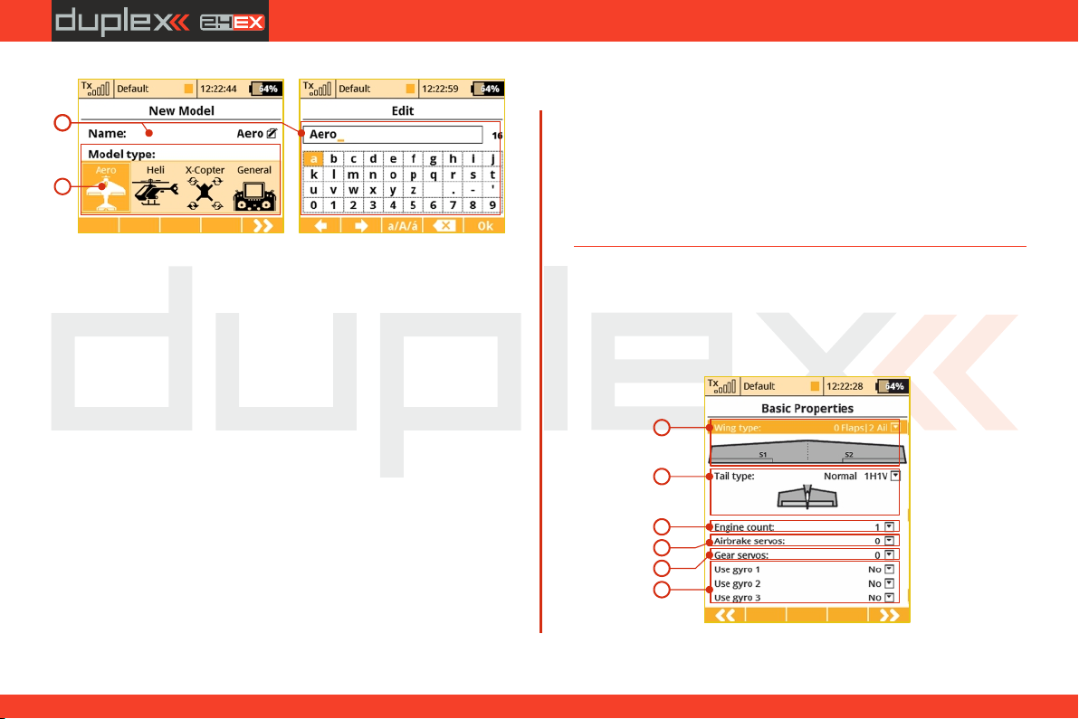
computer radio control system
1
2
1. Model name
Use the „3D Control Selector“ to select the model name menu. You
will enter the model name that you want the transmitter to use when
the model is stored in the transmitter‘s memory.
When you select the "Name“ item, the screen will change into the
"Edit“ menu, where you can use the "3D button“ to enter a name for
your model. Use the "F1“ and "F2“buttons to move the cursor, if
needed, within the name box.
Use the "F3(ABC)“ button to change between lower case letters and
capital letters.
Use the "F4“ button to delete the character at the current cursor
position.
When you finished editing your model’s name, use the "F5(OK)“
button to confirm the name and return to the "New model“ menu.
The model name can be changed even after the model is stored by
going to: "Main menu->Model->Basic configuration“ and
selecting the model name.
2. Model type
The model type selection makes the setup of your model more
EN
efficient by populating the menus with many of the popular options
for each type of model. The possible choices are: Aero, Heli, X-Copter
and General. Once your model is stored it is not possible to change
that model’s type.
Once your model’s name is entered and the type is selected, press
the "F5(Next)“ button to go to the next menu assistant step: "Basic
Properties“. The software will only allow this step if both the model
name and type have been set up.
9.1.3 Basic configuration - AIRPLANE
In this menu you will setup the wing configuration, tail type, number
of motor/engines, number of spoilers, and number of landing gear
servos. Your model’s flight control functions are generated
according to your configuration choices in this menu and the
necessary fixed mixers become accessible.
1
2
3
4
5
6
1. Wing Type
The following wing type options are available:
56
4. 4.
Page 57
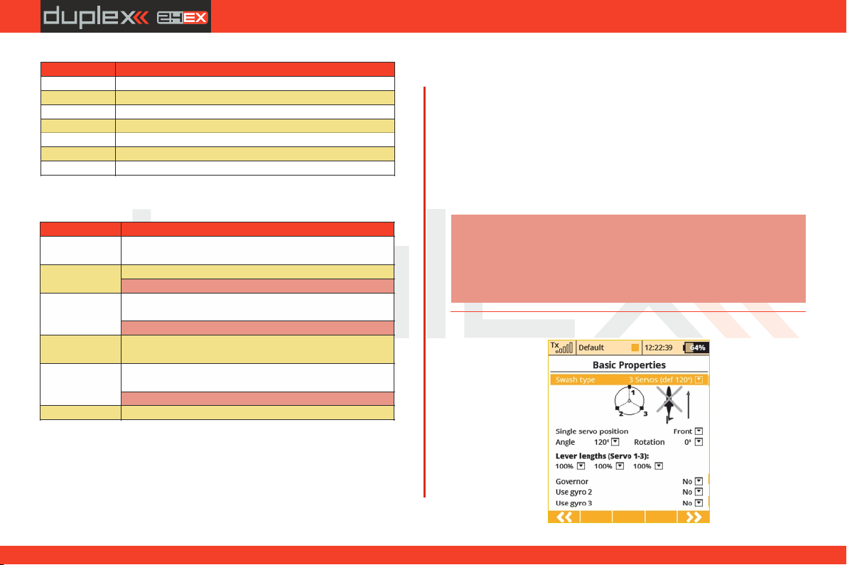
computer radio control system
Type
Description
Standard 1H1V
Standard tail assembly with one horizontal control
(elevator) and one vertical control (rudder)
V-tail 2H
Traditional V-tail
Note: The V-Tail Mix is automatically enabled.
Ailevator 2H1V
Tail assembly with two elevator servos and one rudder
servo
Note: The Ailevator Mix is automatically enabled.
Standard 2H2V
Tail assembly with two elevator servos and two rudder
servos
None –
Elevon/Delta
The model is controlled by the combined control of the
wing surfaces
Note: The Delta/Elevon Mix is automatically enabled.
None
Model without a tail assembly
Type
Description
0FLAP.|1AIL
Only one aileron servo
0FLAP.|2AIL
Two aileron servos
1FLAP.|2AIL
One flap servo, two aileron servos
2FLAP.|2AIL
Two flap servos, two aileron servos
2FLAP.|4AIL
Two flap servos, four aileron servos
4FLAP.|2AIL
Four flap servos, two aileron servos
4FLAP.|4AIL
Four flap servos, four aileron servos
EN
5. Number of Landing Gear Servos in the model
You can select up to 4 landing gear servos. You can then assign the
control of each landing gear servo to a different receiver channel if
needed.
6. Use gyro (1 - 3)
It is possible to create up to three independent functions for
controlling gyro gain. The detailed configuration of individual gyro
gains is then available in "Fine Tuning -> Gyro Setting”.
2. Tail Assembly
The following tail option are available:
Press the "F5(Next)“ button proceed to the next step of the menu
assistant: "Functions Assignment“.
Note:
If you activate the additional function of the gyro in the
active model, after leaving the Basic Properties menu it
is necessary to carry out the control assignment
(Functions Assignment) and then select the appropriate
output channel (Servo Assignment).
9.1.4 Basic Configuration - HELICOPTER
3. Number of Engines/Motors in the model
You can select the number of engines/motors in the model. You can
select up to 4 engines/motors. You can then assign the control of
each throttle to a different receiver channel if needed.
4. Number of Spoiler Servos in the model
You can select up to 2 spoilers servos. You can then assign the control
of each spoiler to a different receiver channel if needed.
4. 4.
57
Page 58

computer radio control system
EN
Swash Plate Type
Enter the type of swash plate your helicopter is using. Refer to your
helicopter’s manual if necessary.
• „3 servos (default 120°)“ – the swash plate controls the
elevator, aileron and collective pitch functions by coordinating three
servos. In the swash plate configuration, the servo control points can
be shifted closer to or farther away from each other around the main
shaft axis using a parameter "Lever length". In case your heli requires
a swash plate configuration of 3 servos (140°) or 3 servos (90°) you
can use the parameter angle with 1° increments.
Within this menu you can also change the effective swash plate
servo „lever lengths“ to compensate for any nonlinear servo arm
travel.
· „ 4 servos (90°) - the swash plate controls the elevator, roll
and collective pitch functions by coodinating four servos in 90°
orientation. You can make the same changes to this type as with the
swash plate described above.
• „Mechanical“ - this swash plate type uses a single servo for
each flight function. This is the swash plate type to select if you are
using a flybarless controller.
Reverse swash plate orientation by 180°
The "Front servo position“ item is accessible only for the swash
plate type "3 servos (default 120°)“. If your helicopter requires, it is
possible with a single button to turn the swash plate configuration in
the setup by 180°.
Swash plate angle
The "Angle“ item is only accessible in the "3 servos (default 120°)“
swash plate type. The angle formed by swash plate points 1 - 2 and 1
– 3 can be configured by the user in 1° increments. This allows you to
fine tune your swash plate configuration as needed.
Rotation
The "Rotation“ Item is only accessible in the "3 servos (default
120°)“ and "4 servos (default 90°)“ swash plate types. This item
allows you to rotate the entire swash plate by a defined angle. This
allows you to add fine tune your swash plate as required by some
scale models.
Servo arm lengths (servo 1 – 4)
This item allows you move your swash plate control points either
closer to or farther away from the axis of rotation. This allows you to
compensate for any nonlinear servo movements.
Governor
In some helicopter setups a governor function is used for motor
control – this allows the motor to run at a constant speed
independently from any collective pitch. If your model helicopter
setup includes a governor which can be controlled through the
receiver then switch on this function. Once you enable this function,
the governor configuration becomes accessible in the „ "Fine Tuning
-> Governor Setting” menu.
Use gyro (2 - 3)
It is possible to create up to three independent functions for
controlling gyro gain. By default, gyro No. 1 is always active.
Theothers are activated in the "Model -> Basic Properties” menu
together with the Governor function.
58
4. 4.
Page 59
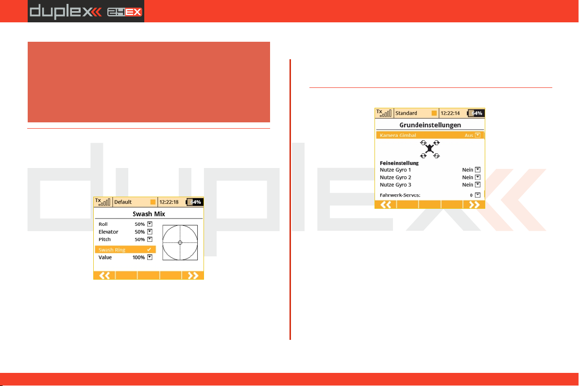
computer radio control system
EN
Note:
If you activate the additional function of the gyro in the
active model, after leaving the Basic Properties menu it
is necessary to carry out the control assignment
(Functions Assignment) and then select the appropriate
output channel (Servo Assignment). Setting the gyro
gain itself is carried out in the "Fine Tuning-> Gyro
Setting menu”.
Editing an item "Value" affects the diameter of the displayed circle,
ie. size of the maximum allowed deflection. The setting is global for
the whole model.
9.1.6 Basic Configuration – Multicopter
9.1.5 Swash mix
Here is where you set up the swashplate CCPM (=Cyclic/collective
pitch mixing) throws for Aileron, Elevator and Pitch. You can fine
tune each of these functions by changing their percentages. If
needed, you can reverse the throws by setting a negative
percentage.
Camera Gimbal
Here you can select the type of camera gimbal used. You can select:
"Off" -> no Gimbal, "base" -> 2 axis gimbal (roll, pitch) or "full" 3 Axis
Gimbal (roll, pitch, yaw).
Use Gyro (1-3)
The user can select up to three independent settings for the flight
Swash Ring
It is possible to activate the function of the cyclic limitation for a
helicopter rotor head. Activating this function causes the restriction
of servo travel in the combined full deflection of the roll and pitch
controls so that the total size of the deflection is always within the
inner area of the displayed circle. Outside the circle there is a kind of a
dead zone of the flight controls.
control system. This allows you to adjust the sensitivity of each axis of
the flight controller while in flight.
Number of chassis / landing gear servos
Here, up to 4 servo functions for the chassis / landing gear servos can
be selected, allowing each servo to be connected to a separate
receiver slot.
59
4. 4.
Page 60
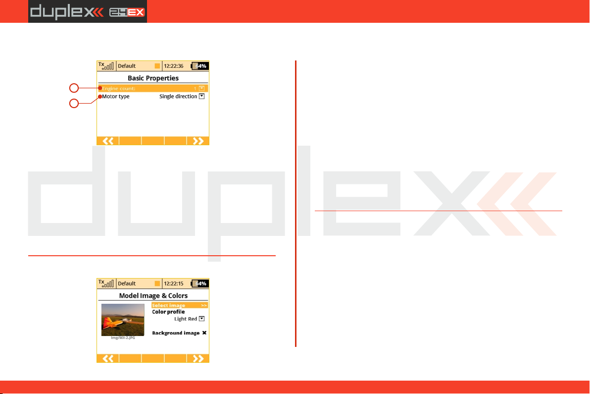
computer radio control system
EN
9.1.7 Basic Configuration-GENERAL
1
2
1. Number of Motors in the Model
This is where you select the number of motors in your model. It is
possible to select 0-4 motors. The number of transmitter control
outputs used to control the motors are automatically increased or
decreased according to number of motors that you select.
2. Motor Type
Do the motors in your model only turn in one direction or are they
able to rotate in both directions?
9.1.8 Model Image & Colors
Model / Wallpapers
You can display two types of model images. A smaller model image
and a larger model image on all screens where the telemetry values
are displayed (Menu - Timers / S e n s o rs - telemetry display).
Background image.
The background image is always visible (behind the telemetry
values). The transparency of the image can also be set, where the full
visibility is specified. Supported image formats: PNG (up to 320x240)
and JPG baseline (up to 1024x768). Please note that large image files
can easily delay the loading of a model memory.
color profiles
There are a wide range of different color profiles for the display.
These color profiles are model-specific and can be selected for each
model separately to your own taste.
9.1.9 Assignment of functions
Based on your selected configuration a list of all flight functions will
be created with basic transmitter channel assignments.
The menu allows you to rename flight functions, assign a flight
function to any arbitratry transmitter stick, switch, knob or slider and
also allows you to set up additional flight function trims.
You can allow the software to automatically assign your flight
functions by pressing the "F2(Auto)“ button and then press the
"F5(Yes)“ button.
60
4. 4.
Page 61
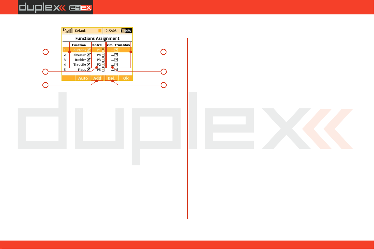
computer radio control system
1
2
5 6
1. Flight function Renaming
By editing each "Function“ item you can rename a flight function
from its original name to any name that you choose.
2. Assignment of a Control Element to a Flight Function
By editing each "Control“ item you can assign any arbitrary stick,
switch, knob or slider to a given flight function. The proportional
channels 1 – 8 are marked P1–P8. The markings Sa-Sf designate
switches with the same designation as on the transmitter front
panel.
When you select one of these items, you will enter the menu: "Select
control input“, see chapter 9.7. The assignments can easily be
verified by the graphic found beside the control element description
in the "Control “ section, which shows the actual setup of the
assigned control element.
3. Choice of an Additional Trim
The transmitter allows you to also create a trim function for any
arbitrary flight function. By editing one of the „Trim“ items you can
assign an arbitrary control element (stick, switch, knob or slider) to
control the trim of the selected flight function. When you select one
4
3
EN
of these items, you will enter the menu: "Select control input“, see
chapter 9.7. The assignments can easily be verified by the graphic
found beside the control element description in the " Trim “ section,
which shows the actual setup of the assigned control element.
The trim functions for the gimbal sticks P1-P4 are automatically
assigned to the quad push-buttons located below the gimbals.
It is not necessary to assign them manually.
4. Range of Additional Trim
If you set up a trim function, you can use the "Trim-Max“ to set the
maximum trim influence on the given flight function. The default
value is 50%. If you set the value to 0%, the trim control element will
not have any effect on the flight function at all. If you set a value of
100%, the trim control element will control the flight function to its
full travel.
5. Adding a Function
With the „F3(New)“ button you can create (add) your own flight
function.
6. Deleting a Function
With the „F4(Delete)“ button you may delete the selected flight
function.
Make sure that you have assigned all of your flight functions to the
correct transmitter control elements (stick, switch, knob or slider)
and make sure that the trims are assigned and functioning as you
wish. By pressing the "F5(Next)“ button you will enter the next
assistant step, the "Servo assignment “ menu.
61
4. 4.
Page 62
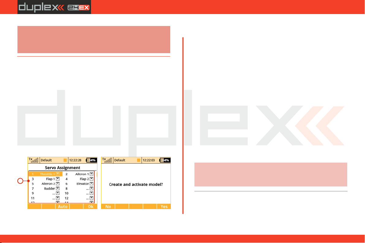
computer radio control system
EN
Note:
The initial assignment is carried out in accordance with your
selected transmitter mode. If the initial assignment is incorrect,
check the transmitter mode setup in the "Main menu->System>Configuration- >MODE 1-4 menu.
9.1. 10 Servo Assignment
This menu shows the assignment of transmitter output functions to
the receiver channels. This assignment can be changed as you wish.
The order number at the beginning of the column shows the
channel number and the assigned transmitter output function is
next to it. In this menu you can rearrange your output functions as
needed, i. e. any transmitter function can be assigned to any of the
receiver channels. The only restriction is the number of channels
which the transmitter can control (16 channels). The transmitter can
automatically set up your servo configuration based on your
previous model setup. If you want the transmitter to automatically
assign the servos in the default order, press the "F3(Auto)“ button
and then press the "F5(Yes)“ button.
a)
1
1. Assignment of Transmitter Output Functions to Receiver
Channels
Select the required receiver channel and press the "3D button“.
Now you can choose which function you want assigned to the
selected receiver channel.
With the "F5(Next)“ button you will enter the next step of the
assistant which creates and stores the model into transmitter
memory.
a) The assistant asks you to confirm the creation of the model by
displaying the question "Create and select a model?“. If you answer
by pressing the "F1(No)“ button, the model will not be saved and
you will return to the assistant to continue with further
configuration of your model.
If you press the "F5(Yes)“ button, the model will be stored in the
memory and at the same time will be activated. After that, you are
automatically taken to the "Servo Setup“ menu. Your stored model
can, of course, at any time be configured by selecting the "Main
menu->Model“> "Servo Setup“ menu.
Advice:
Once your model is created and activated, you should
bind your receiver with the transmitter and then
proceed with "Servo Setup“.
62
4. 4.
Page 63
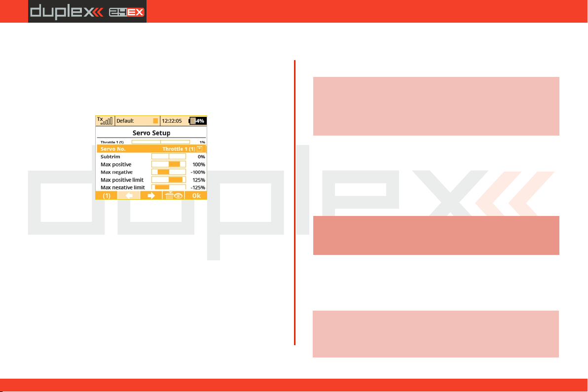
computer radio control system
9.1.11 Servo Setup
This menu is for the additional tuning of output functions of the
transmitter->receiver channels->servos. The assignment of a
transmitter output function to a receiver channel is shown in the
upper part of the menu (first item below the menu description).
1. Display of a Receiver Channel Throw
In the upper part of the menu the actual throw of the selected
channel is displayed using a live graphic. If you make a change to
your setup in this menu, you will immediately see how the output
will be influenced by the change.
2. Selection of Receiver Channel
In the first position F1 in the lower bar you see the actual selected
channel. With the F2() or F3()buttons or by editing the item "Servo
#“ you will select the receiver channel which you intend to
configure.
EN
3. Center (Subtrim)With this item you can adjust the servo
neutral position of the selected receiver channel.
Advice:
When building a model try to mechanically adjust the
neutral positions as perfectly as possible. If you are
going to use a high "Center (Subtrim)“ value in order to
set up a servo neutral, the resulting servo throw will be
restricted.
4. Max Positive/Max Negative Throw
This item sets the useable end points of the transmitter output
function, i.e. how far the transmitter control element can move each
surface. This functon is used to set your maximum control throws for
flight and to limit any potential binding of a linkage or surface. This
limit can be exceeded by the use of mixes or combined functions.
Note:
The size of the maximum throw can influence trim
settings, dual rate throws and other proportional
setups.
5. Max Positive/Max Negative Limit
These restrict the absolute throw of the receiver channel output.
This limit can never be exceeded by any combination of functions or
mixes.
Advice:
You can adjust the throw limit to prevent a surface or
linkage from hitting a mechanical stop or to prevent the
servo from over-driving its mechanical throw range.
This allows you to prevent mechanical servo damage.
63
4. 4.
Page 64
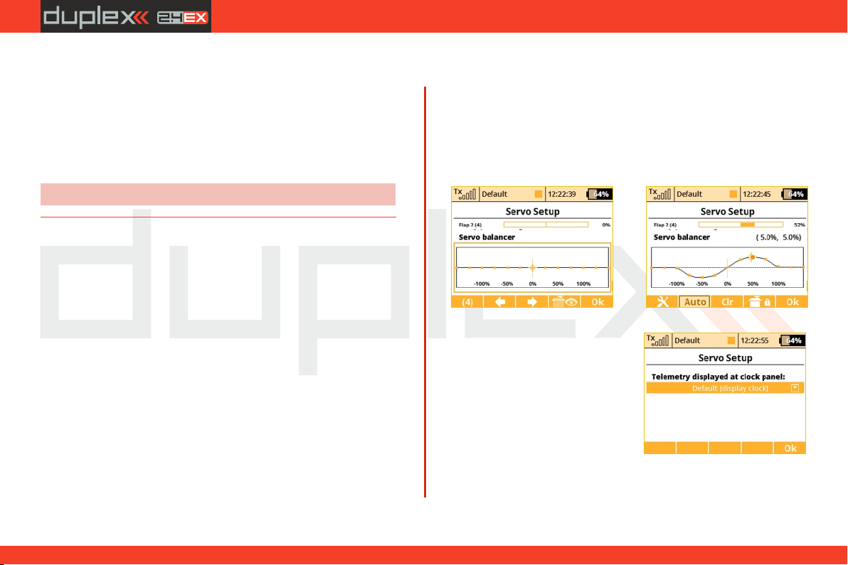
computer radio control system
EN
6. Servo Reversing
Use this item to reverse the direction of a servo’s travel.
7. Delay of positive/negative
This item allows you to delay the servo channel‘s travel time
between both end points. This can be defined for the positive and for
the negative value (each travel direction). For instance, the opening
of a landing gear can be slower than when it retracts.
Advice:
This function is great for timing retract gear servos.
9.1.12 Servo balancer
The function of the servo balancer is designed for large models that
have control surfaces driven by mechanically linked servos. Since
each servo can be preset from the factory in a different way and
mounting servos into the model is not always accurate, it is now
possible to set servo travel algorithmically to ensure minimum
mechanical stress during the movement of the controls.
Thus it is possible to assign a separate curve to each output channel,
which is applied as the last operation before sending the deflections
to the model. Because it is applied last, the curve is ultimately
applied to trims, mixes, dual rates, etc., so that servos of the same
control surface always move together equally. The Servo balancer
can alter the curve of the servo by a maximum of ±10% with a
resolution of 0.1%.
1. After you highlight the graph of the servo balancer, push the "3D
button”. This enables editing of the servo curve. Now, always one
control point is highlighted according to current servo deflection. If
the current servo position is -30%, the nearest highlighted control
(*depends on equipment)
point is located in -25%. It is then possible to move the point
upwards or downwards by turning the „3D button” to the right, or
respectively to the left. In "Auto" mode (the „F2 button” is
highlighted) simultaneous shifting of neighboring control points
occurs, so that the resulting curve is precisely smoothed. Then you
can select another control point by moving the servo control and
alter this point until the mutual mechanical stress of servos during
the movement is minimal.
2. After pushing the "F1 button”
wh en the servo balancer is
highlighted, the speed dial is
displayed. Here is where you can
select one telemetry parameter,
which will appear at location of the
digital clock on the top bar of the
screen. This way you can select, for
example, displaying the instant
current draw from the batteries,
wh ich is ver y h elp ful wh e n
balancing different servo travels.
64
4. 4.
Page 65
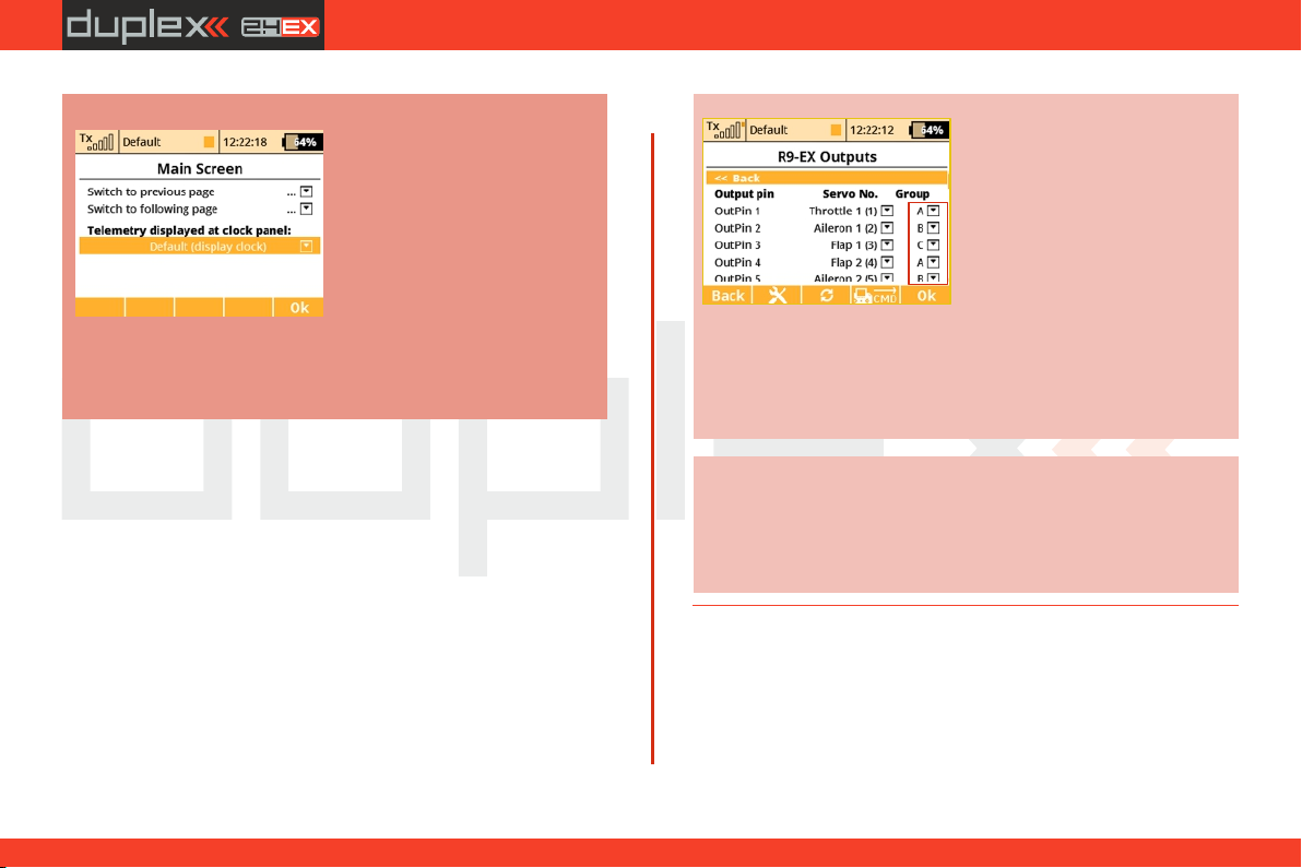
computer radio control system
EN
Note:
3. The "F2 Auto” button enables switching between automatic and
manual selection of control points in the servo balancer edit mode.
When selecting control points manually, push the "3D button” to
move to the next point; pushing the "ESC” button activates the
previous check point. When editing in the manual mode, you move
(as opposed to the automatic mode) only one control point, the
others remain unchanged.
If the "F3 Clear” button is pushed for a short time, it quickly clears a
control point (which must be highlighted). If the "F3 Clear” button is
pushed and held for longer time, the whole curve is cleared to a
default state.
4. By pressing the F(4) button you can lock the function movement.
So that you don't have to hold the stick at the exact position while
editing the balancer curve.
Setting the d isplay of th e
tel emetry data on the top
menu bar of the screen is saved
a s a p a rt o f t h e m o de l
configuration and iti s isplayed
again when the transmitter is
switched on. Alternatively, it is
p o s si b l e t o a d j u s t t h e
displayed data in the "Timers /
Sensors - > Ma in Screen” menu.
It is possible to select any
simple numerical value, except
GPS coordinates.
Advice:
Advice:
To optimize the servo travels via servo balancer, we
recommend that you use an ampermeter (or eg. the
current measurement from the MUI sensor displayed in
the telemetry window) and always try to make sure that
the current running through servos as low as possible.
If you use several mechanically
linked servos to control a single
wing surface in the model as
shown in this example, we
recomm end setting all the
se rv os b el on gi ng t o t hi s
surface into one output group
(Group A-C). In the picture this
is done via the Device Explorer
application. In this way the
servos w ill r ecei ve contro l
pulses at the same time and
their movement will thus be
synchronous.
65
4. 4.
Page 66
computer radio control system
EN
9.2. Fine Tuning
9.2 Fine Tuning
- Extended program functions for fine tuning your models
• Flight Modes
• Digital Trims
• Flight Mode Trims
• Dual Rate/Expo
• Function Curves
• Aileron Differential (This menu is only accessible in the wing configuration
0FLAP│2AIL and higher)
• Free Mixers
• V-Tail (This menu is only accessible in the „V-tail“ tail configuration.)
• Butterfly (This menu is only accessible in wing configuration 2FLAP│2AIL and
higher)
• Ailevator (This menu is only accessible in the „Ailevator“ tail configuration)
• Delta/Elevon ( This menu is only accessible in wing configuration „None-
Elevon/Delta“)
• Gyro/Governor
• Throttle Limiter(Helicopters only)
• Snap Roll
9.2.1 Flight Modes
The purpose of programming Flight Modes is to provide the ability
to activate a group of settings that will optimize your flight control of
your model. Flight Modes can just as easily represent settings for
Take Off, Soaring, Landing and much more. They can be used in any
particular situation where different settings of basic flight
parameters is desirable. The DS-12 gives you the advantage of a wide
variety of programing options.
Up to 10 different flight modes (depends on activated transmitter
equipment) are available for every single model. Each one of these
flight modes can be named differently for instant recognition. Only
one of the flight modes can be active at any given time. With a little
practice you will discover that creating your flight modes in logical
order can prevent confusion in a critical situation. Flight mode
control can be assigned to any of the switches, sticks, or knobs of the
transmitter.
Flight Mode Configuration
• Some of the configuration settings come in two options. G-
global (globe symbol) and S-Separate. Switching from G to S, system
let you set up each flight mode individually.
Warning:
When you switch from Global to Separate settings, all
values will be copied directly to existing flight modes.
• If the flight mode configuration is set to S, each flight mode’s
values can be set independently from the other flight modes. When
you switch to different flight modes, the pre-set position of an
output (a control surface, for example) can be changed to optimize
the control system of your model.
• Also, if the flight mode configuration is set to S, different
variables for each function can be assigned to each flight mode. The
assigned control switch can control multiple values within each
flight mode.
• After creating a flight mode, this will become system wide
settings for all future models.
66
4. 4.
Page 67
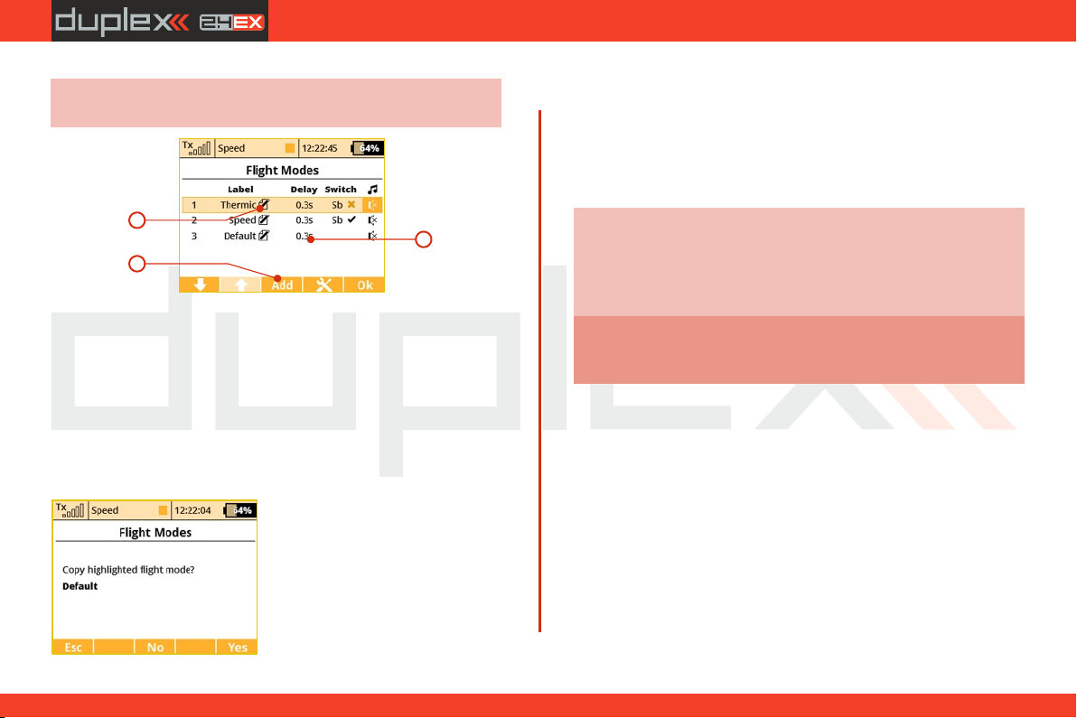
computer radio control system
EN
Advice:
If no flight mode is required, do not change the pre-set
configuration.
2
3
1
Adding Flight Modes1.
Pressing the “F3 (Add)” button creates a new flight mode. Simply
highlight existing mode and press “F3 (New)” button. A copy
confirmation menu appears on the screen, use the function keys to
continue.
Press the “F5 (Yes)” button to create copy of the existing flight mode.
Press the“F3 (No)” button to create a new flight mode.
Press the“F1 (Esc)” button to be taken to main flight mode menu
screen.
Naming Flight Modes 2.
We recommend naming flight
modes according to their function,
for example: Take Off, Soaring,
Autorotation….
Flight mode names/labels can be
easily edited at any time.
3. Flight Mode Delays
The time delay function can help smooth the transition from one
flight control state to another. Sudden changes in the positions of
your control surfaces can negatively affect performance or even
create a critical situation. The Time delay can help you avoid this
situation.
Advice:
If the desired result is not already tested or fully known
(maiden flight), always make sure that you have set
enough time delay for all of the changes to be
implemented and that you have plenty of time to
respond properly.
Warning:
4. Flight Mode Activation
A f light mode can be ac tivated by any control de vice
(Switch/Knob/Stick). When you select a switch and by editing its
desired assignment you can activate and pick the position at which
this Switch/Knob/Stick or Logical Switch will turn flight mode ON or
OFF (see chapter 9.7). You can use the visual indicator in the switch
column to help you determinate the ON or OFF switch position
foreach flight mode.
Throttle hold is not affected by the time delay. This
function will always be performed instantly.
• Check Mark – ON Position
• X Mark – OFF Position
When the flight mode is activated, the flight mode name can be seen
at the top of the desktop screen.
67
4. 4.
Page 68
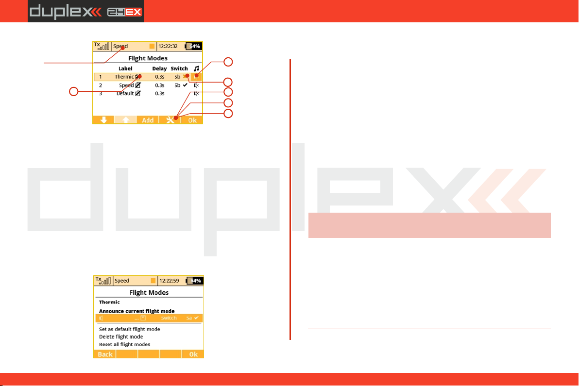
computer radio control system
EN
Name of the
current flight mode.
5
Flight Mode Activation Priorities5.
If you have created multiple flight modes that can match a given
flight condition but that vary in their specific details (Landing in
strong or light wind). You can create the order in which those modes
can be turned on. The Numeric order will determine your priorities.
A lower number equals a higher mode priority. The initial flight
mode has always the lowest priority.
6. Flight Mode Default and Reset
Any of the created flight modes can be pre-set as a future default.
Simply highlight your choice and press the “F4 (Opt.)” button to see
confirmation menu. Pick the, “Set as a Default Flight Mode” option
and the flight mode is now set as your new default.
9
4
6
7
8
7. Deleting a Flight Mode
To delete a flight mode:
Highlight the desired flight mode and press the “F4 (Opt.)” a)
button to see the options menu.
Scroll and select the “Delete flight mode” option and press the b)
“F5 (OK)” button to make the final confirmation.
The initial flight mode is set as a default and can not be deleted.
8. Flight Mode Reset
All of the flight modes can be reset to basic settings at the same time.
Simply highlight any flight mode and press the “F4 (Opt.)” button
then use the “Reset all flight modes” option to reset all flight modes
to their basic settings. All previous changes will be deleted and the
flight modes will be reset to the G (Global) setting.
This is useful when you are setting up a new model from a copied
model and you want different flight modes.
Advice:
After you make a configuration change or perform a
reset, always check all flight modes.
9. Announcement of the current flight mode
It is possible to assign a WAV file to each flight mode, which is played
at the moment when the selected mode is activated.
10. Flight mode announcement after flipping a switch
It is possible to assign an arbitrary switch to the flight mode voice
announcement. After switching on, the actual flight mode will be
announced (the selected WAV file will be played back).
68
4. 4.
Page 69
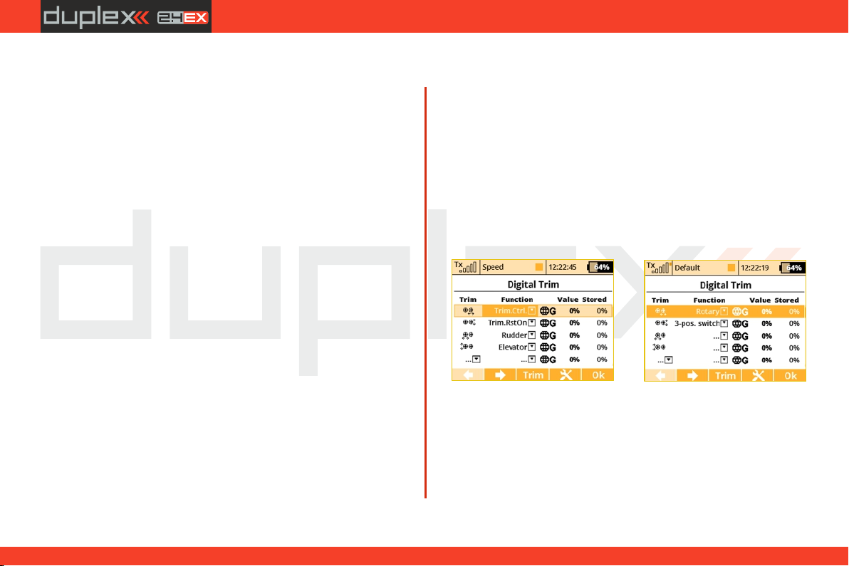
computer radio control system
EN
9.2.2 Digital trim
Fully programmable digital trims are located right under the
transmitter gimbals as a set of four directional buttons. All
adjustments and step changes are made in the “Digital Trim” menu.
You can assign different trim ranges and trim steps to every trim
control function.
The trim dialogue has been divided into two . You screens, a) and b)
can switch between each of them by using the "F1 Left" and "F2
Right" buttons. The “F3 (Trim)” button switches your desktop
display to the main trim screen where you can instantly observe your
setup changes.
As you can see from the screen , you can assign any function that a)
will be influenced by that particular trim. It is also possible to
deactivate the trim so that it doesn’t influence any function (simply
unselect the assigned function). This is mostly important for pilots of
various multicopters or helicopters equipped with advanced
stabilization electronics.
Special trim functions
Digital trims can be used independently as controls for any function.
It is possible to assign the special functions "Trim.Ctrl" or
"Trim.RstOn" (Trim – Automatic reset) to any digital trim.
- Trim.Ctrl (Trim control) – enables using a specific trim
independently from model functions. The transmitter remembers
the trim value after shutdown. After pressing the trim button no
superior functions are trimmed, only internal state of trim is
incremented.
- Trim.RstOn (trim control with automatic reset) – enables using
the specific trim independently from model functions. The
transmitter does not remember the value of trim after shutdown.
After loading the model, the trim value is always 0%. In combination
with the logical switches this option is suitable for a sequential
switching between flight modes or playing sound sequences.-
–the up/down positions 3-Position momentary switch emulation
are active only as long as you hold the corresponding trim button.
Default value is otherwise 0%.
- Rotary function –Every time you press the trim button the value is
increased or decreased according to trim step. This creates an
arbitrary number of predefined positions of the trim control which is
useful for example for switching flight modes of stabilization
systems. Default value is -100%.
The operational modes of the trims have also been extended (see
picture ). There are currently these options:c)
Global – the specified trim will have equal settings for all flight
modes.
Separate – ever y flight mode has its own independent
configuration of the trim.
69
4. 4.
Page 70
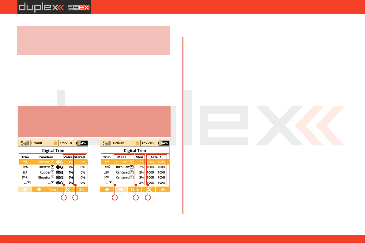
computer radio control system
EN
Advice:
For the maiden flight we recommend using larger trim
steps. After familiarizing yourself with your model’s
behavior you can switch to smaller steps for finer
trimming.
Flight-Mode Group (A/B) – if you are using several flight modes and
you want to share trim settings among a few of them just set one
of the groups FA or FB for the particular trim. Each group has its
own settings which are then shared. Note: If you change from
Global to any Flight-Mode Group, the trim mode in other flight
modes than the current one will become Separate.
The rest of the parameters are described below:
Note:
If you change a flight mode from Global to either of the
Flight-Mode groups the trim mode for the rest of the
flight modes (except for the one you are currently
editing) will change to Separate.
a)
1. Value – shows the actual trim rate.
2. Stored – shows the stored value of trim memory function.
3. Mode – here you can specify a basic behavior of the trim:
1 2 3 4 5
b)
• Centered mode – by default, the trim affects only the servo
center, the endpoints remain untouched.
•Linear – shifts the whole servo travel, including endpoints.
• Thro-Low – affects the servo low endpoint and the entire
curve, except for the high endpoint.
• Thr-L50% – affects the servo low endpoint and curve below
.50%. This does not affect the curve above 50%
• Thro-High – affects the servo high endpoint and the entire
curve, except for the low endpoint.
4. Step – indicates, how much the value of trim changes each time
the trim button is pressed.
5. Rate (+,-) – determines maximum limits used for the trim.
In the picture below you can see how various trim modes influence
the servo output (trimmed to ca 50% of range). However, you
cannot use any trim mode at any time:
V-Tail configuration - You can specify the trim mode only for the
elevator function, not for rudder since these functions are linked
together.
Delta/Elevon configuration - You can specify the mode only for
ailerons, not for elevator.
Helicopter using CCPM mix - You can specify the mode only for
pitch function, not for elevator nor roll function.
If you use two or more trims to adjust a single function, the resulting
trim rate equals to a sum of all rates that are participating on this
function. However, the transmitter uses always only a mode defined
for the first trim.
70
4. 4.
Page 71
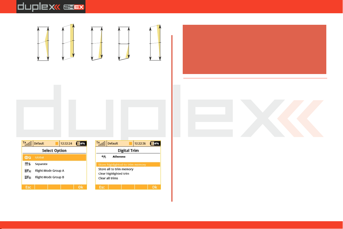
computer radio control system
EN
High Endpoint
Center
Low Endpoint
Centered mode Linear mode Throttle Low Throttle Lower 50% Throttle High
Center
Center
Center
Center
Press the "F4 button" to display additional trim options. See picture
Warning:
The Autotrim feature, when active, always influences the
model functions currently assigned to the particular trim
buttons (except for throttle function which is never affected by
this feature). The Autotrim function does not take effect on the
auxiliary incremental trims. Please be very careful if you
assign trim buttons to any function that is not controlled by a
spring centered stick. It is advised to disable the Autotrim
completely in such a case.
d). You can store the currently highlighted trim (for example Ailerons
in the picture) to trim memory, or you can apply the trim memory
function to all trims.
How it works: The actual rate of the highlighted trim (or all trims,
respectively) is copied into a special register. (See the last colum of
picture )Once the rate is stored, the trim rate column value will be a)
9.2.3 Flight Mode Trims
This menu allows you to set the function output position (if needed)
for each flight mode individually. For example: if your elevator needs
to be raised in one of your flight modes but not the others. Each
function output can be set either globally or separately.
cleared. This applies always to all flight modes. The trim memory
function is beneficial if you want your trims zeroed although some
offsets have been set. When processing, the transmitter sums the
actual trim rate and its stored value.
1. Servo Position
A transmitter output channel can be assigned to more than one
receiver output channel if needed. Adjusting the values in the
individual columns marked “S1-S4” will change the position of the
servo (surface) for each output function. The servo position is
displayed as a percentage of the total servo travel.
Pressing the “F3 (Clr)” button resets the highlighted line’s travel
values to 0%.
Pressing the “F1 (Sym.)” turns ON/OFF the lock which allows each
c)
In the picture there are two more options available: Clear highlighted trim and Clear all d),
trims. After confirmation, this option clears the actual trim value (or all trim values,
respectively) and similarly zeroes the previously stored values (trim memor y). This always
applies to all flight modes.
d)
output to be adjusted either together (symmetrically), or
independantly.
71
4. 4.
Page 72
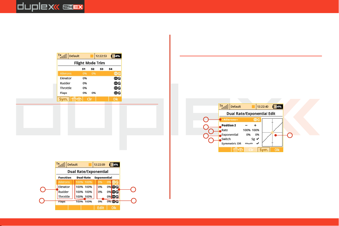
computer radio control system
EN
2. Trim Travel Global or Separate Setting
The servo trim position for each function output can be set either
collectively for all flight modes by selecting the “G-(global)” or
individually for each separate flight mode by selecting “S-
(Separate)”.
9.2.4 Dual Rate/Exponential
This menu allows you to set up dual or triple rates for any of your
created output functions. Any of the channels can be set with
dual/triple rates and custom exponential settings. Exponential
settings can significantly increase your control precision by making
your stick movements (around center point) yield less control
movement. At the same time, the end points of the control surface
throw can be set to its extremes.
a
b
d
c
Channel namea)
Dual/Triple rate travel settingb)
Exponential settingc)
Global or separate flight mode settingd)
By highlighting one of the channels and either pressing the “F4
(Edit)” button or by pressing the “3D Control” button you will
access the individual control‘s settings page.
Fine Tuning – Dual Rate/Exponential menuand check the "Prop."
option. If you assign any proportional control as a DR switch, you will
be able to set the DR/Expo values moreprecisely.
a
b
c
d
e
f
Channel name and global/separate settinga)
Current switch positionb)
Percentage of travelc)
Exponential rate settingd)
Assignable switch optione)
Graphic interfacef)
g) Symmetric Dual-Rate checkbox
72
4. 4.
Page 73
computer radio control system
EN
1. Expo Global or Separate Setting
Expo configuration for all channels can be set collectively for all
flight modes by selecting the “G-Global ” symbol or you can allow
individual expo settings in each separate flight mode by sellecting
the “S-Separate” symbol.
2. Expo/Dual Rates Switch Assignment
By selecting “Switch Option” you will access the“Select Input (e)
Control” screen where you can select the control element that you
wish to control the dual rate and/or expo for the selected function.
For simple dual rates, a 2-position switch is sufficient. For more
complex triple-rates, any 3-position switch or one of the fully
proportional channels can be selected. Then your selected switch is
assigned. While the “Select Input Control” screen is still visible you
can change the switch travel by using “F2 (Prop.)” button to select
the proportional setting. The correct function can be verified in the
“Dual Rate Edit” screen by activating the switch and observing the
position number change to “Position 1-2” for a two position switch
or, if 3-position switch is used, to “Position 1-2-3”. For a 3-position
switch you will also need to use the "F1 (Centr)“ button before all
three positions are correctly displayed.
Expo/Dual Rates Travel Setting 3.
Every switch position can define a different function and (b)
exponential value. Any change made to the settings can be directly
observed on graphic interface . (f)
Dual/Triple rate setting is defined by percentage of the travel . A (c)
higher number increases travel, a lower number decreases travel.
Expo rate is defined by percentage of the function curve . Zero (d)
rate represents linear function. As expo rate increases linear travel
changes to exponential “curve” travel.
Exponential and Dual rate settings combined with flight modes
create virtually unlimited customizability.
4. Symmetric/asymmetric rates
The DS-12 transmitters offer possibility of asymmetric rates for
rudder and ailerons. After highlighting and unchecking "Symmetric
DR", then pushing the F4 (Sym.) button it will be possible to adjust
the aileron rates to the right and left independently.
Advice:
For smooth, precise flight we highly recommend setting
up exponential and dual rates.
73
4. 4.
Page 74
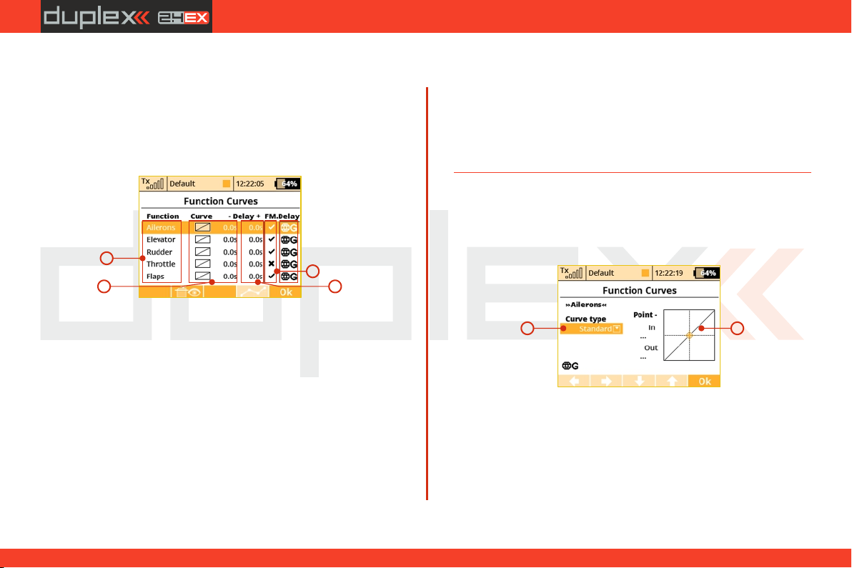
computer radio control system
EN
9.2.5 Programmable Function Curves
Function curves define the relationship between the actual position
of your stick/switch/knob and the position of the servo. This screen
displays the menu of all assigned functions , graphic interfaces (a)
(b) (c), and programmable time delays . All adjustments can be
visually inspected right away in the servo monitor page by pressing
the “F2 (Servo)” button.
a
b
a) Function name.
Graphic interfaces.b)
Time delay.c)
Global or Separate setting.d)
e) Flight Mode Delay Enable
Flight Mode Delay Enable
In the menu "Fine Tuning->Function Curves”, it is possible to
activate/deactivate a delay for a specific function while switching
between flight modes. Specifically, in the picture, it is the 5th column
(FM. Delay) that allows this. The activation of a delay also might be
flight-mode specific (i.e.: in the first flight mode the activated and in
the second mode it is disabled). There are some specific conditions
where setting this option for one function has an effect in another
function.
(*depends on equipment)
e
c
• If V-Tail is selected, the option influences both rudder and
elevator.
• If Delta wing is selected, the option influences both elevator
and aileron.
• If electronic heli swash mix is selected, the option influences all
functions of the swash plate (roll, pitch, and elevator).
1. Programming Function Curves
The Function Curves programming screen can be accessed by
highlighting “Curve” window and pressing “3D Control” button or
directly accessed by simply pressing “F4” button. Either way, you will
be taken to the highlighted function’s curve option screen.
a
a) Function curve type.
b) Graphic interface.
The function curve can be selected from the existing list or from
custom, previously modified options.
Available Options:
74
b
4. 4.
Page 75
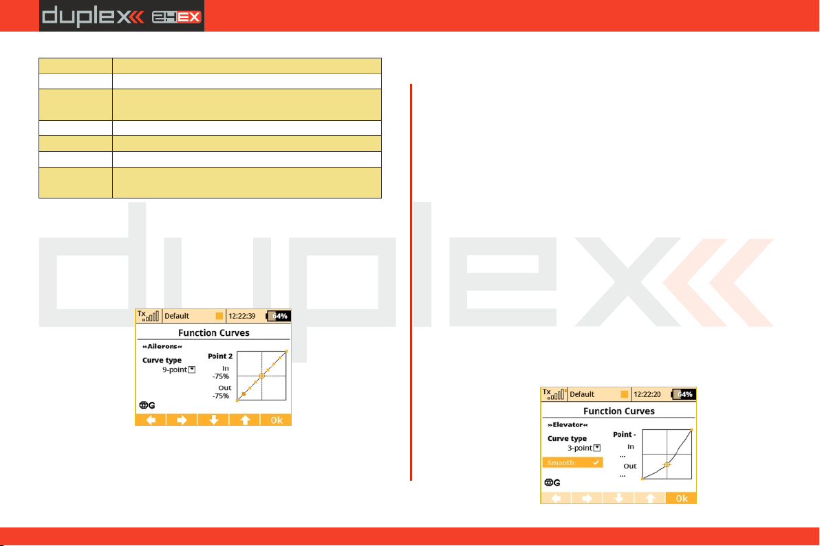
computer radio control system
Standard
Linear values, set In/Out point
Constant
Constant value, set point
3-Point, x>0,
x<0, |x|
3-Point curve, set value for 3 points
5-Point
5-Point curve, set value for 5 points
7-Point
7-Point curve, set value for 7 points
9-Point
9-Point curve, set value for 9 points
+Pos, - neg,
+-Symmetrical
4-Point end to end curve, set value for 4 points
2. Function Curve Setting
You can select the function curve which best fits your application.
You can choose one of the pre-programmed 3-9 point ones or select
any of custom symmetrical curves.
You can edit a function curve from inside the graphic interface by
moving the displayed control points.
EN
By pressing the “3D Control” button you can switch between the
individual curve points. Pressing the “Esc” function will return you
to the previous control point. On the left side of the graphic interface
you will see the percentage representation of your selected control
point’s position. “In” and “Out” percentage numbers represent
actual input and output position of a given control point.
3. Function Curve Delay
The time delay function can help smooth the transition from one
state to another. The function of the “Delay” is to slow down the
movement of a control surface in relationship to the position of the
stick. Example: a negative number “-” slows movement of the rudder
from moving right to left, a positive “+” number slows rudder
movement from left to right.
4. Global or Separate Function Curve Setting
The function curve configuration for all channels can be set
collectively for all flight modes by selecting the “G-Global” symbol
or you can set individual function curve settings in each separate
flight mode by sellecting the “S-Separate” symbol.
5. Smoothed function curves
(see Fine Tuning –>Function Curves, Fine Tuning –>Free Mixes, Fine
Tuning –>Butterfly)
All of the points can be moved in both horizontal and vertical
directions. Using the “3D Control” or the “F3” and “F4” buttons you
can move the curve points in a vertical direction and in a horizontal
direction by using the “F1” and “F2” buttons.
4. 4.
75
Page 76
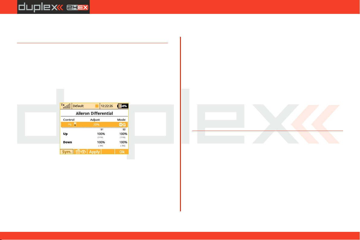
computer radio control system
EN
Using the SMOOTH function, you can completely smooth out your
curve between the selected points.
9.2.6 Aileron Differential
The aileron differential function reduces the downward travel of the
aileron(s) to help eleminate any adverse yaw tendencies in rolling
maneuvers. Semi-Symmetrical airfoils with an aileron in the down
position induce higher drag than when the aileron is in the up
position. Therefore, the aileron travel up and down has to be set
differently. The number of aileron servos displayed depends upon
the selected wing type of your airplane; the maximum number is
four “S1-S4”.
1. Aileron Differential Global or Separate Setting
The aileron differential for all channels can be set collectively for all
flight modes by selecting the “G-Global” symbol or you can allow
individual aileron differential settings in each separate flight mode
by sellecting the “S-Separate” symbol.
2. Aileron Differential Setting
All of the ailerons can have different travel ranges. The different
adjustments are displayed in columns marked "S1-S4”. The number
of servos in use is equal to the number of displayed setup columns.
The travel range for each servo can be set. Scroll and highlight either
the “Up” or “Down” menu line with “3D Control” button. Press the
"3D Control“ button to access and edit the settings for each servo. If
the servos need to be adjusted independantly, use the “F1 (Sym.)”
button to unlock the servo travel for adjusting the individual values
in the selected menu line.
3. Tuning of Aileron Differential
You can now assign a proportional control and the adjustment rate.
When moving the control, the differential rates are updated
accordingly: up-rate is increased and the down-rate is decreased
depending on the adjustment rate and position of the control. In the
picture the real differential rates are enclosed in parenthesis.
The "F(3) Apply” button clears the adjustment rate and stores the
real differential values into the editable fields so that the control no
longer has any influence.
9.2.7 Ailevator Function
The ailevator function uses two servos for the elevator channel. Both
sides can be programmed to be controlled independently. With
ailevator function both servos can be mixed together with ailerons
and work in sync for better roll control. The Ailevator mix has to be
activated by choosing the “Ailevator2H1V” tail setting. Unless you
have previously chosen a different percentage for one of the tail
mixes, the initial settings for “Ailevator” function are 100% of the
elevator travel and 0% of the aileron travel.
76
4. 4.
Page 77
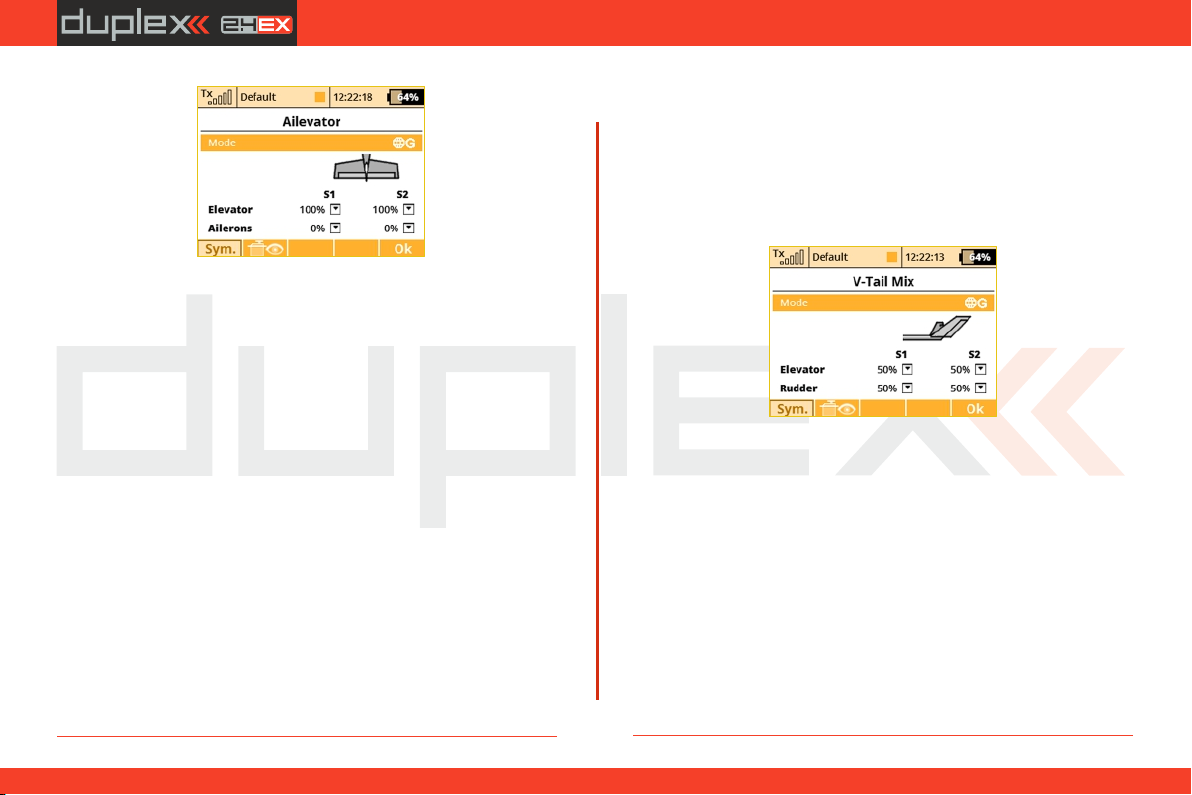
computer radio control system
1. Ailevator Global or Separate Setting
The Ailevator configuration for both channels can be set collectively
for all flight modes by selecting the “G -Global” symbol or you can
set individual Ailevator settings in each separate flight mode by
sellecting the “S-Separate” symbol.
2. Ailevator Setting
Ailevator configuration has four different adjustable parameters.
The lines marked “Elevator” and “Aileron” contain two columns
“S1” and “S2” which represent the elevator and aileron surface
throws as a percentage. Scroll and highlight the lines marked as
“Elevator” or “Aileron” with the “3D Control” button and press the
“3D Control” button to access the individual setting of each servo. If
the servos need to be adjusted independantly, use the “F1 (Sym.)”
button to unlock the servo travel for adjusting the individual values
in the selected menu line.
EN
9.2.8 V-Tail Mix
If your model is equipped with a V-Tail, The two basic tail functions
(rudder and elevator) are mixed to control the tail of the airplane. The
V-Tail mix has to be activated by choosing the “V-Tail 2H” tail setting.
Unless you have previously chosen a different percentage for one of
the tail mixes, the initial settings for “V-Tail” function are 50% of the
rudder and elevator travels.
1. V-Tail Global or Separate Setting
The V-Tail configuration for both channels can be set collectively for all
flight modes by selecting the “G-Global” symbol or you can set
individual V-Tail settings in each separate flight mode by sellecting the
“S-Separate” symbol.
2. V-Tail Setting
The V-Tail configuration has four different adjustable parameters. The
lines marked “Elevator” and “Rudder” contain two columns “S1” and
“S2” which represent the elevator and aileron surface throws as a
percentage. Scroll and highlight the lines marked as “Elevator” or
“Rudder” with the “3D Control” button and press the “3D Control”
button to access the individual setting of each servo. If the servos need
to be adjusted independently, use the “F1 (Sym.)” button to unlock the
servo travel for adjusting the individual values in the selected menu line.
77
4. 4.
Page 78
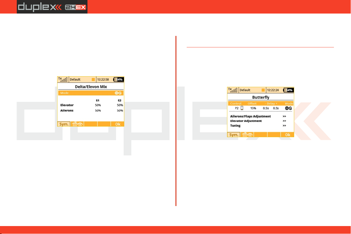
computer radio control system
EN
9.2.9 Delta/Elevon Mix
The Delta/Elevon Mix uses two servos for the control of both the
elevator and aileron functions. This mix is most commonly used for
Delta type aircraft. The elevon mix has to be activated by choosing
the “None – Elevon/Delta” tail setting. Unless you have previously
chosen a different percentage for one of the tail mixes, the default
settings for the “Delta/Elevon” function are 50% of the aileron and
elevator travels.
1. Delta/Elevon Global or Separate Setting
The Delta/Elevon configuration for both channels can be set
collectively for all flight modes by selecting the “G-Global” symbol
or you can set individual Delta/Elevon settings in each separate
flight mode by sellecting the “S-Separate” symbol.
2. Delta/Elevon Setting
Delt a/Elevon configurati on has four diffe rent adjustabl e
parameters. The lines marked “Elevator” and “Aileron” contain two
columns “S1” and “S2” which represent the elevator and aileron
surface throws as a percentage. Scroll and highlight the lines
marked as “Elevator” or “Aileron” with the “3D Control” button and
press the “3D Control” button to access the individual setting of
each servo. If the servos need to be adjusted independantly, use the
“F1 (Sym.)” button to unlock the servo travel for adjusting the
individual values in the selected menu line.
9.2.10 Butterfly Mix (Crow Mix)
The basic configuration of the butterfly mix (also known as crow) is
created by using ailerons, flaps, and elevator flying surfaces. The
Butterfly/Crow mix is helpful for maintaining speed during fast
descends and creating controlled drag for spot landings.
1. Butterfly/Crow Activation
The Butterfly mix can be activated by any control element
(Switch/Knob/Stick). By selecting the switch and by editing the
desired assignment you can activate and select the position at which
this Switch/Knob/Stick or Logical Switch will turn the Butterfly mix
ON or OFF. This menu line includes a visual graphic to show the ON or
OFF position of your selected switch.
2. Butterfly/Crow Delay
The time delay function can help smooth the transition from one
state to another. Function of the “Delay” is to slow down the
78
4. 4.
Page 79
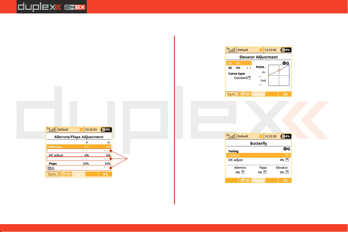
computer radio control system
EN
movement of the control surfaces during the change. Increasing the
number on the positive side “+” slows the deployment while
increasing the number on the negative side “-” slows return of the
surfaces to their original positions.
3. Butterfly/Crow Global or Separate Setting
The Butterfly/Crow mix configuration settings can be set collectively
for all flight modes by selecting the “G-global” symbol or you can
allow individual aileron differential settings in each separate flight
mode by sellecting the “S-Separate” symbol.
4. Butterfly/Offset
You can set an offset to the butterfly control so that there will be a
specified dead zone at the beginning of the control stick’s travel.
Actual values of
airbrake rates.
T h e v a l u e s
shown depend
on adjustments
m a d e i n
Butterfly Tuning
m e n u ( see
below).
a. Ailerons/Flaps Adjustment
In the Ailerons/Flaps Adjustment menu you can set all the travel
needed for butterfly braking (for the flaps and ailerons). Also, you
can set a parameter called Diff. adjust which influences the aileron
differential. Positive values increase the upper travel of the aileron
servos, negative values increase the lower travel of the aileron
servos.
b. Elevator compensation
The butterfly mixing is always from zero to the full stick position so
the curve is a little bit modified to control the whole travel range. You
can choose between a standard curve, constant and X-point curve
types.
c. Butterfly Tuning menu
Screen of the Butterfly menu allows you to fine tune all braking
travels through one proportional control (stick, knob or switch). The
values you set in this screen are added/subtracted to the
79
4. 4.
Page 80
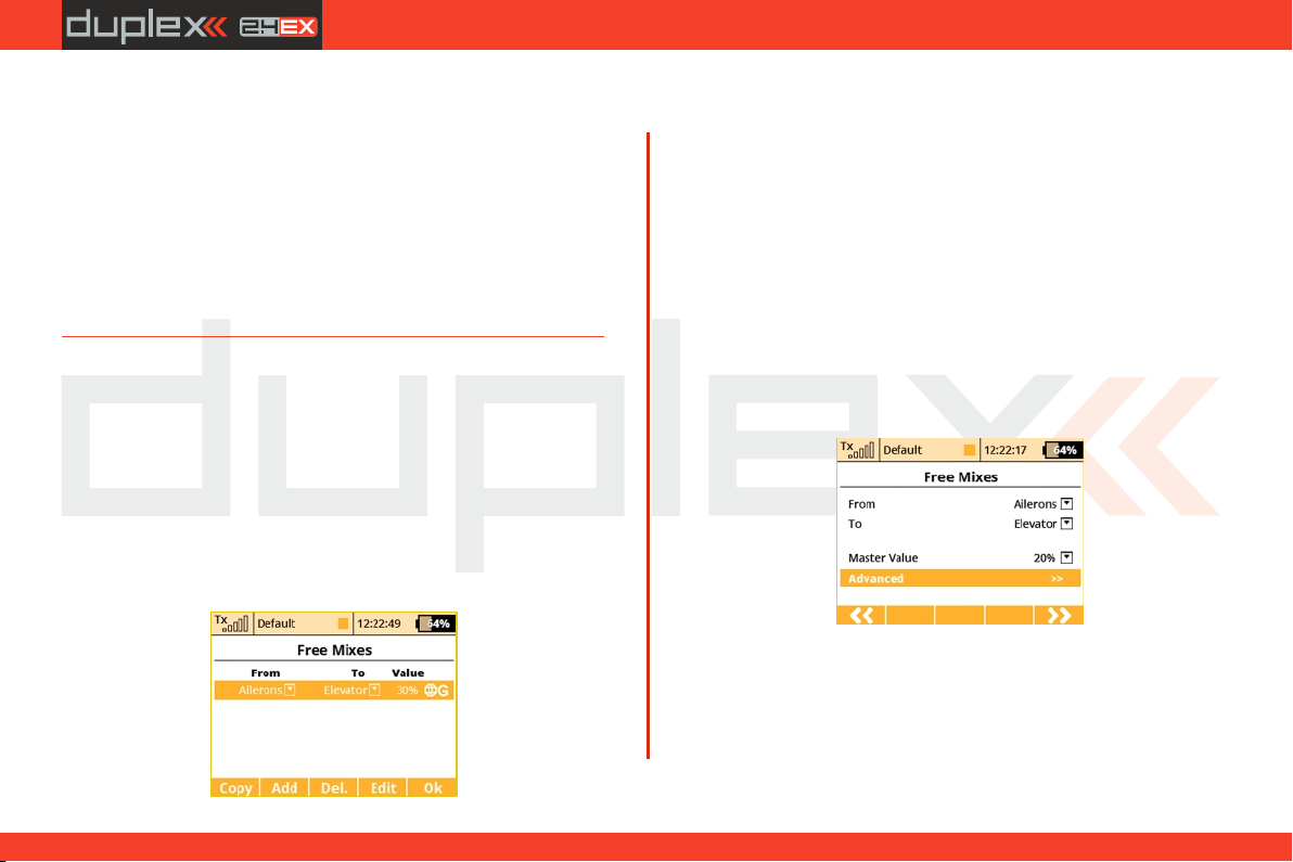
computer radio control system
EN
appropriate butterfly travels. The way these values influence servo
deflections depends on the position of the butterfly's control stick
and the position of the butterfly's Tuning control.
The "F3Apply” button operates similarly as in the Aileron
Differential menu. If you press this button, the values set in the
"Butterfly Tuning” menu are copied into the appropriate travels in
the "Butterfly Ailerons/Flaps/Elevator Adjustment” menu. After
that, all values in the Butterfly Tuning menu are initially set to zero (so
that the tuning control no longer has an effect).
9.2.11 Free Mixes
The Free (programmable) mixes are used to make a second or „slave“
channel react as a result of the original channel’s input or by moving
any Switch, Knob or Stick. Any of the channels can be (Freely) mixed
with any other function, assignment or logical switch. Up to 30 free
mixes can be programmed for any given model. The primary
channel (“Master/From”) specifies the control or input function,
while the channel that reacts to the Master is called the “Slave/To”
channel. The “Master Value” represents the percentage of "slave“
channel travel output performed when the "Master“ channel
function is used.
1. Copying a Free Mix
Highlight an existing free mix and use the “F1 (Copy)” button to
create a copy of the existing mix.
2. Creating a Free Mix
Use the “F2 (Add)” button to create a new free mix. The Primary
channel called “Master/From” specifies the input function, while
the channel that reacts to the Master is called the “Slave/To”
channel. The last variable on the screen is the “Master Value” which
represents the percentage of the slave channel’s mix/travel. After
your model‘s basic configuration is finished, use the “F5 (Next)”
button to exit the free mix screen. If you need to make any changes
simply highlight the desired free mix and press the “F4 (Edit)”
button to reach the advanced settings menu for that free mix.
a). Free Mix Setting
The free mix configuration settings can be set collectively for all
flight modes by selecting the “G-Global” symbol or you can allow
individual free mix settings in each separate flight mode by
sellecting the “S-Separate” symbol.
80
4. 4.
Page 81
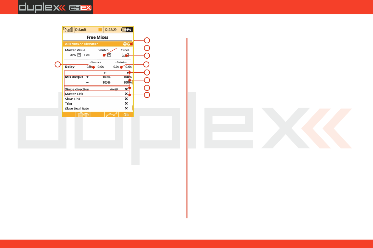
computer radio control system
EN
d) Free Mix Deployment Delay
a
b
c
d
e
g
h
i
j
The time delay function can help smooth the transition from one
state to another. Values adjusted in the “Source” item will slow down
full mix deployment when the mix is ON (switched ON or always ON)
and the master channel changes its value. In this item, when you add
a delay to only one side (- or +), the mix deployment will be slow in
one direction only (-100% to 100%) or (100% to - 100%). When you
add a delay to both the negative (-) and the positive (+) sides, then
your mix will be slowed in both throw directions.
e) Free Mix Activation/Deactivation Delay
The "Switch“ values can only be when you have assigned a switch to
turn the mix ON and OFF. This delay operates independently from
the "Source“ values. The positive side of a delay is applied if the mix is
activated using Activation Switch. The negative side is used if the mix
b) Free Mix Activation
A free mix can be activated by any Switch/Knob/Stick. By selecting
“Switch” and by editing the desired assignment you can activate
and choose the position at which this Switch/Knob/Stick or Logical
Switch will turn the mix ON or OFF or even control its throw
proportionally. This menu line includes a visual graphic to show the
ON or OFF position of your selected switch. If you do not select any
switch, then the mix is always ON.
c) Free Mix Curve Programming
This programming screen can be accessed by highlighting the
“Curve” item and by either using the “3D Control” button or by
pressing the “F4 (Curve)” button. By accessing the “Mixer Curve”
function screen you can select the mix curve which best fits your
application.
is deactivated and both slow down any fast reactions while turning
the mix ON and OFF.
f) Free Mix Multiple Servo Settings
If the mix uses more than one output function as the slave, then the
“Output Mix” menu will appear. This menu allows you to edit the
settings for the individual slave servos (S1-S4).
g) Free Mix Directional Positive/Negative Movements
Once the free mix function is created you can edit the advanced
settings menu so that the mix will either add to or reduce a slave
function‘s movement. To do this, you can set the mix value as a
positive percentage or a negative percentage.
h) Using Another Free Mix to control a Free Mix
A free mix can be controlled by just a control input function (Master)
or it can also be controlled by another free mix’s control function
81
4. 4.
Page 82

computer radio control system
EN
(Slave). Here is how to create a free mix whose input is controlled by
an existing free mixer output:
• To allow a free mix to control another free mix you must enable
the “Slave Link” option. This allows the free mix to act as input for
other free mixes. Use the “3D button” to highlight and select this
option. You will see a check mark if the option is enabled and an X if it
is disabled. You will also use the (+) or (-) to determine the mix
direction.
• To allow a free mix to be controlled by another mix you must
enable the “Master Link” option. This allows the free mix to accept
the input from other free mixes. Use the “3D button” to highlight
and select this option. You will see a check mark if the option is
enabled and an X if it is disabled. You will also use the (+) or (-) to
determine the mix direction.
i) Free Mix Trim Settings
This item allows you to enable or disable whether trim functions will
influence the free mix or not.
j) Free Mix Control by Dual Rates
With this item you can activate or deactivate the “Slave Dual-Rate”
function for the free mix. This settings allows the slave output to be
affected by dual rate inputs. All adjustments can be visually
inspected right away in the servo monitor page by pressing the “F2
(Servo)” button. Pressing the “F5 (Ok)” button returns you back to
free mix screen.
k) Aileron Differential
This option is displayed only after you create a mix from any function
to Ailerons. When this option is activated, the output of the mix will
be influenced by the aileron differential settings. If this option is
deactivated, the output of the mix is transmitted directly to the servo
without any modifications. Uncheck this option if you want to use
aileron differential fine tuning without affecting throws of the mixes
applied on ailerons.
3. Deleting a Free Mix
Press the “F3 (Del)” button to delete the highlighted free mix.
4. Configuration & Setting
A free mix programming screen can be accessed by highlighting the
selected mix and then pressing the “F4 (Edit)” button.
82
4. 4.
Page 83
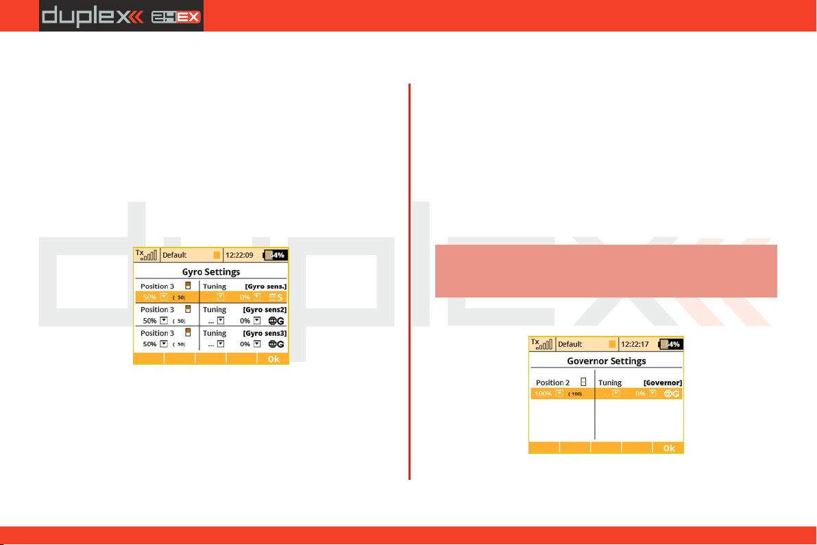
computer radio control system
EN
9.2.12 Governor/Gyro
Typically, a gyro is used to stablize a model helicopter along its
vertical axis (rudder). One channel is reserved so that you may adjust
the gyro sensitivity (gain) from the transmitter. Also, a separate
channel can be reserved for the control of a throttle governor. The
governor can be enabled when you create the model or later from
the "Model >Basic Properties“ menu. This menu allows you to
adjust the settings for both of these output channels. The
Governor/Gyro settings can be set collectively for all flight modes by
selecting the “G-Global” symbol or you can allow individual
Governor/Gyro settings in each separate flight mode by sellecting
the “S-Separate” symbol.
1. Gyro Settings
By default, the gyro sensitivity is assigned to the three position "Si“
switch. This allows you to have three different settings (Position 1,
Position 2, Position 3) for the gyro sensitivity. You can always assign
this function to a different transmitter control element (knob, slider,
switch) in the "Model, >Function Assignment“ menu. The Gyro
settings can be set collectively for all flight modes by selecting the
“G-Global” symbol or you can allow individual Gyro settings in each
separate flight mode by sellecting the “S-Separate” symbol.
In the Gyro settings menu it is possible to edit up to three main
values for each gyro function in all flight modes separately according
to the position of the main control/switch.
Moving the switch to the selected position causes an automatic
update of the depicted values in the appropriate line. Set the main
value of the gyro gain to the needed value (highlighted in the
picture), eventually also assign an appropriate control for fine tuning
– here it is necessary to set also the percentage range of the control
influence. For each position of the main control it is possible to
individually assign an independent control for fine tuning of the
gyro gain. The resulting applied gain value is displayed in
parentheses (-50% in this case).
Note:
Negative values of gyro gain indicate the gain in
"Normal" mode, positive values indicate the gain in the
"Heading-lock" mode.
2. Governor Settings
If you have the governor function enabled, by default, the governor
sensitivity is assigned to the three position switch. This allows you to
83
4. 4.
Page 84
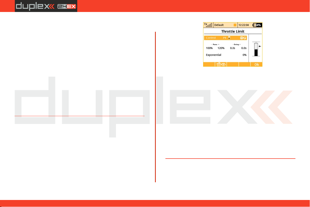
computer radio control system
have three different settings (Position 1, Position 2, Position 3) for the
governor sensitivity. You can always assign this function to a
different transmitter control element (knob, slider, switch) in the
„Model, >Function Assignment“ menu. The governor settings can
be set collectively for all flight modes by selecting the “G-(globe)”
symbol or you can allow individual governor settings in each
separate flight mode by sellecting the “S-Separate” symbol.
Like in Gyro gain settings, it is also possible to select up to three main
values for governor RPM control in the Governor settings menu (0%
means zero RPM, 100% means full throttle). It is also possible to
assign a specific control to each governor position (switch, stick or
knob), which can precisely tune required RPM – in this case it is
necessary also to specify the range of the influence of the tuning
control to the RPM. The resulting applied value of the Governor
function is displayed in the parentheses. The setting can be global
for all flight modes or separate for each mode.
9.2.13 Throttle Limiter
If you have several flight modes and all of them have specific throttle
curves, the Throttle Limiter might help you to get the motor's RPM
safely from the lowest to the maximum RPM that is controlled
byyour throttle curve.
You are free to choose any control device (proportional or a switch)
that will operate as a speed limiter. It doesn't allow the throttle to go
any higher than the position that this control shows. The limiter
(*depends on equipment)
EN
operates within a specified range (negative and positive rate, “- Rate
+”). Using the “-” rate you can set the lowest motor RPM you want to
use. This is the point where the limiter begins its operation. The “+”
rate represents the maximum possible output of your throttle
channel. If your application needs full throttle, you should set the “+”
rate to a value higher than 100% so that the full throttle output is not
limited.
It is possible to set some delay for this control (if it is assigned to a
switch) so that the motor goes smoothly from low to high RPM (and
vice versa). Finally, the Exponential parameter enables you to
finetune the output at lower RPM and the whole acceleration curve.
The throttle limiter also influences mixes where the throttle acts as
the source. The trim function is not influenced by the throttle limiter.
If a control device is not assigned, the throttle limiter function is
disabled.
9.2.14 Snap Roll
The snap roll function is intended for aerobatic pilots who want an
instant stunt controlled by a single switch. There are two modes of
the snap roll function:
84
4. 4.
Page 85
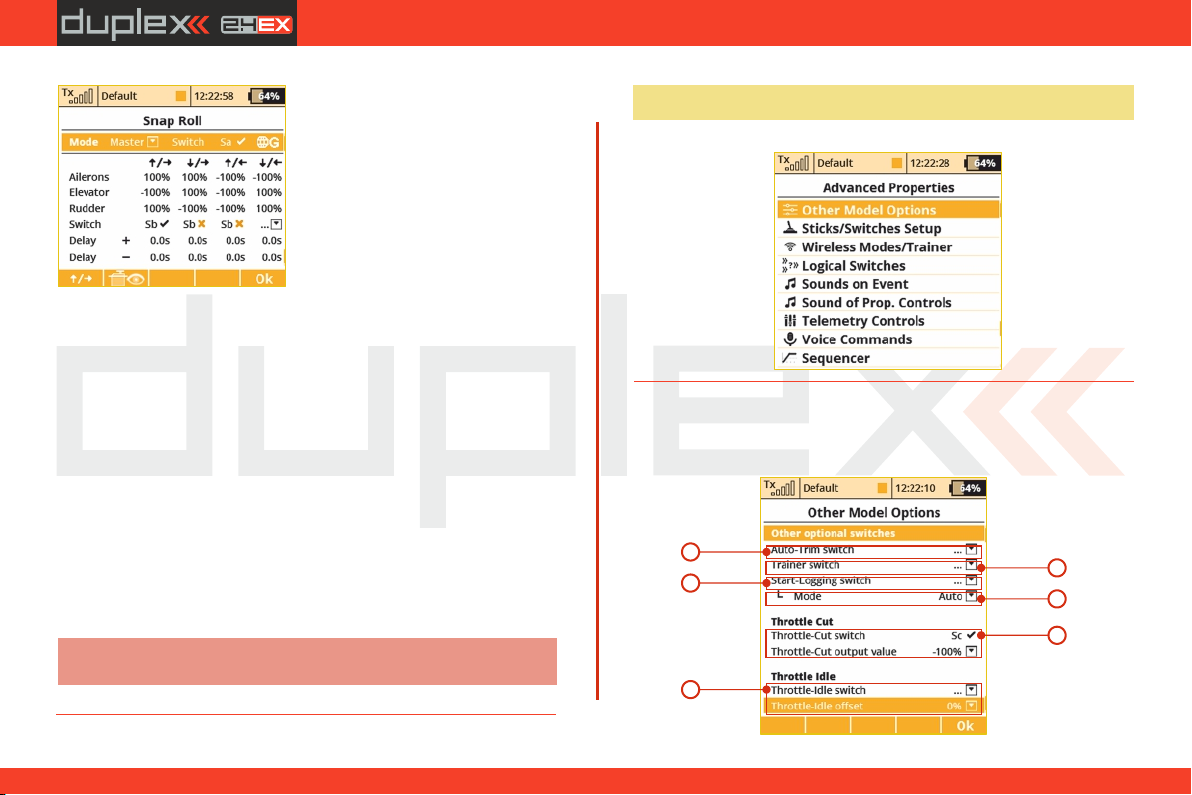
computer radio control system
Sep arate switch es fo r eve ry
direction. The priority goes from
up/right direction (highest) and
continues until down/left (lowest).
Master mode – the stunt itself is done by activating a master 1.
switch (Sa in this case). The other switches are taking care of the
direction of the stunt.
Single mode – the stunt is done immediately after any 2.
direction switch is activated.
You may enter your desired properties for ailerons, elevator and
rudder separately for every direction. There are four directions
available (up/right, down/right, up/left and down/left), each one is
controlled by a separate direction switch. Each element may store its
own fade-in/fade-out ramp which is defined by the rows “Delay +”
and “Delay -”.
All options may be either flight-mode-specific or global. You can see
the current state of the snap roll function in the bottom left corner of
the display.
Note:
This function is not available for helicopters, v-tails or delta
wings.
EN
9.3 Advanced Properties
Advanced programming menu for DS-12.
9.3.1 Other Model Options
This menu contains additional, special features of the DS-12
transmitters.
1
3
5
2
3a
4
85
4. 4.
Page 86
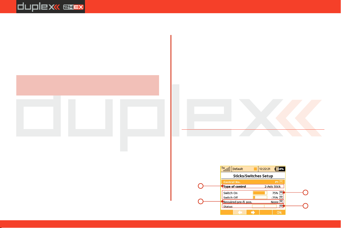
computer radio control system
EN
1. Auto-Trim Function
Auto-Trim function can be activated using any assigned switch,
knob or stick. Once this function has been activated you can trim
your model using transmitter gimbals. The direction and speed of
the trim adjustment is determined by stick movement. Larger stick
movements equal a faster trim response. When the Auto-Trim
function is active, the transmitter gimbals do not change their
standard response. The transmitter is still in normal operation mode.
Advice:
It is advised to use the automatic trim function only for
the maiden flight, after proper trimming is done we
recommend disabling this function.
2. Trainer Function
The Trainer function can be set so that it may be activated using any
assigned switch, knob or stick.
3. Telemetry Recording
The Telemetry recording function can be set so that it may be
activated using any assigned switch, knob or stick. The data stream is
recorded on the internal SD memory card. All data can be found in
the “Log” directory of the transmitter software after connecting the
Tx to the PC via a USB port. Active data recording is indicated on the
upper edge of the main desktop screen by a blinking circle. A solid
square graphic indicates that recording is stopped.
3a. Mode
By default ("Auto" mode), the telemetry starts recording after any
timer is activated, Start-logging switch is flipped or Start button on
the main screen is pressed. If the "Start/Stop" mode is selected, the
status of recording is always controlled by the position of your
selected Start-logging switch.
4. Throttle Cut Setting
This safety feature is mainly for models using glow or gasoline
engines as their main source of power. Electric models can also
highly benefit from this safety feature. The Throttle Cut function can
be activated using any assigned switch, knob or stick. By editing the
“Output Value” item, the throttle output will move to the user
defined (completely off) throttle position once the assigned switch
is activated.
5. Throttle Idle Setting
This feature is used to set the idle position for your throttle and will
prevent your engine from shutting-off when you move throttle stick
to its low position. The minimum throttle setting is defined by
editing the “Idle Offset” value. When this function has been
activated, the minimum throttle setting (idle point) is defined by the
offset value as a percentage. Standard throttle function is not
affected by the idle offset setting.
(*depends on equipment)
9.3.2 Sticks / Switches Setup
This menu contains System Stick/Switch settings and configuration.
Various functions can be activated by any Switch, Stick or Knob
position. Switch setting enables you to set the points when your
desired function/timer/telemetry can be turned ON or OFF.
1
2
3
4
86
4. 4.
Page 87

computer radio control system
EN
1. Switch & Stick Type
The first menu line item lists the control’s number and the second
item lists the type of control element. Using the “F2” and “F3”
function buttons you can scroll through channels, with the “F5 (Ok)”
button you can exit the menu screen.
By default, the switch types are always automatically detected,
however, it is also possible to overwrite any of the auto-detected
switch types with a user-defined type. The choices are: "Auto" which
keeps the auto-detection running, "None" that disables the
particular input control, standard "Std. Switch", "3-Pos. Switch",
"Button" and "Proportional". Any value other than Auto will disable
auto-detection for the specified control. Remember, these settings
are global and are applied to all models. The only model-specific
"Type of control" property applies to stick-switches Sk and Sl. This
feature is useful, for example, if you want to have a standard switch
that behaves like a spring loaded switch equipped with button
memory.
2. Switch ON/OFF Points
Any proportional function can be set as a system switch. This menu
item enables you to assign the travel percentage at which a desired
function can be turned ON or OFF.
“Switch-ON” – The point when the control element positon will
switch a function ON.
“Switch-OFF” – The point when the control element positon will
switch a function OFF.
By default, the system setting for all proportional channels and for all
inputs is set to function the same as a 3-position switch.
a) A function above this point is considered to be “Switch ON”
b) A function in this range (middle) can be considered to be either
“Switch ON” or “Switch OFF”
c) A Function below this point is considered to be“Switch OFF”
If the switch setting is set at same level for “Switch ON” and “Switch
OFF”, the proportional channel/function output will be the same as
a 2-position switch.
3. Required Preflight Position
For any functions assigned to the Switch, Knob or Stick, any preflight
initial position can be programmed. If the pre-programed Switches,
Knobs or Sticks are not in required preflight position while model is
being activated, system will refuse to switch to this model. The
transmitter screen will display the function that is not in
preprogrammed, correct preflight position.
4. Function Status Display
Position and status of the control is displayed in the status bar. On
the right side of this menu you can see the status of the switch
function as an “x” or check mark.
1) Setting Example
If you have installed the optional a button/switch in your left or right
stick, scroll thru the Control No. Menu line and pick the function
switch “Sk” or “Sl” if the button switch is installed in your right stick.
Pick one of the “Type of Control” switch options:
• “2-Position Switch”
• “3-Position Switch”
• “Button”
For any functions assigned to the chosen switch, knob or stick, any
preflight initial position can be programmed.
87
4. 4.
Page 88
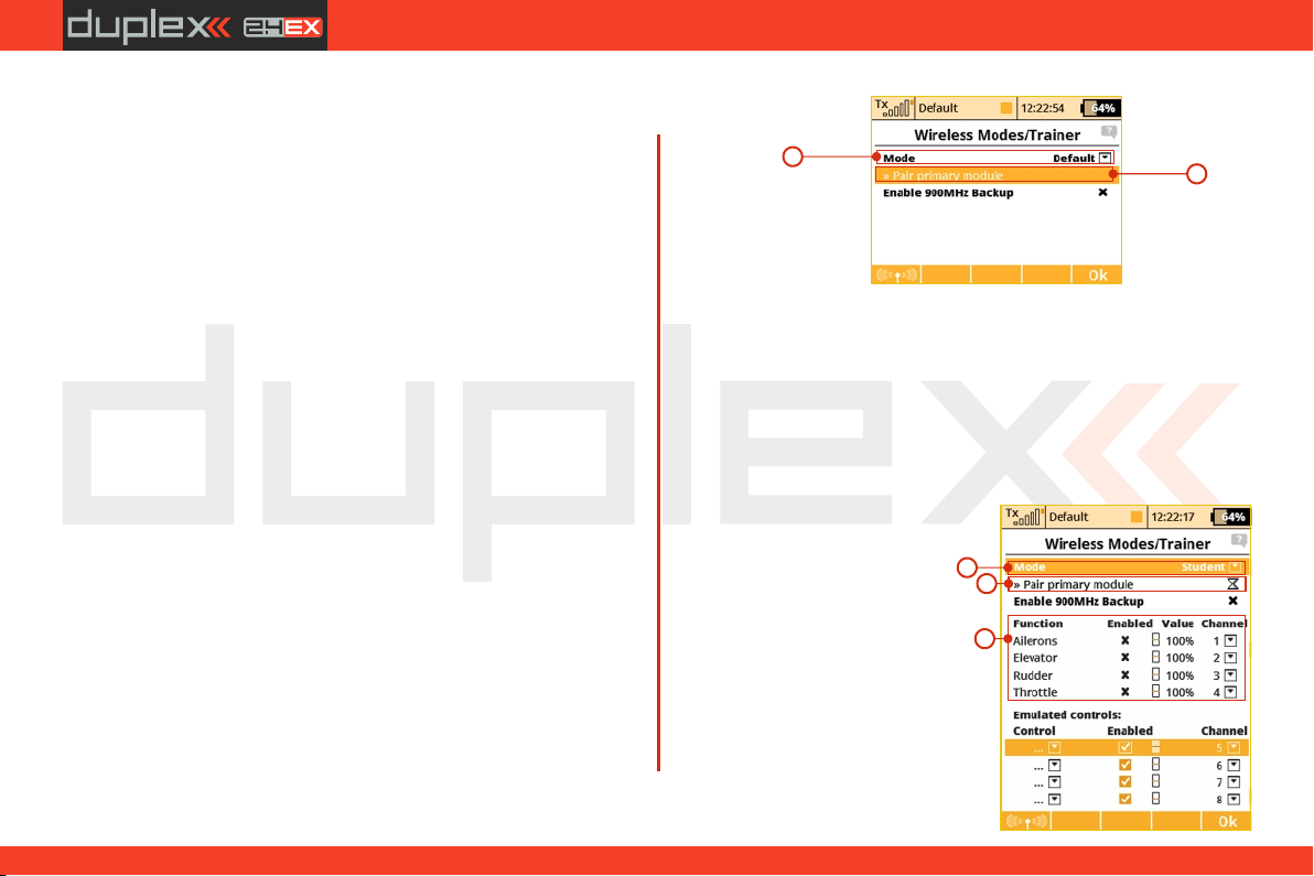
9.3.3 Wireless Modes/Trainer
computer radio control system
EN
The transmitter RF module can operate in one of three modes. For a
detailed explanation. (see section 5) The wireless RF setting is
programmed to the memory of individual models (receivers). While
programming a selected model you will need to configure the RF
module settings. The only exception for the system is the “Trainer”
mode. If the particular model has been programmed in Trainer
mode, this setting will not change if the Tx is turned ON or OFF.
For safety reasons, the “Trainer” RF mode will be switched
automatically to “Default” RF mode when a different model is
selected in the transmitter.
DS/DC-14-16-24 radio systems are excellent tools for instructor
pilots. Basic training for a student is not different from flying his own
model. Both the instructor and student have their own JETI
transmitters, all communication between the transmitters is done
wirelessly. The instructor decides when to give control of the model
to the student and when it’s time to step in. The instructor’s (DS/DC14-16-24) primary transmitter RF module communicates with
model and the secondary RF module communicates with student’s
transmitter (DS-12). The Student’s transmitter (DS-12), if set to
“Student” mode and uses 2.4 GHz RF module to communicate with
instructor’s transmitter.
“Default” Wireless Mode
a. Selection
b. RF module bind control menu line
“Student” Wireless Mode
If student’s transmitter if set to “Student” mode, any dual-rates, mixes
or any other advanced features are disabled in the student’s
transmitter.
a) Mode Selection.
b) Binding initialization of the Instructor transmitter‘s primary RF
module or special wireless “Trainer” module by JETI.
c) Channel function assignment.
88
a
a
b
c
b
4. 4.
Page 89
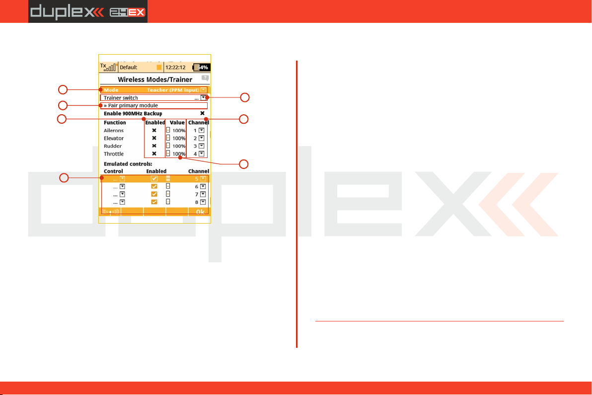
computer radio control system
EN
“Instructor” Mode
a
c
d
g
a) Mode Selection.
b) Assigned trainer function switch, when the switch is activated,
control of the model is transferred to the student.
c) Connect the PPM signal from the "Student" transmitter to the
DS-12 PPM input (Jack).
d) Channel function assignment. Some or all of the functions can
be controlled by student.
e) Instructor/Student control authority values. This setting limits
the amount of control for the student. If the instructor is
assigned a 60% control value to a particular channel, and
student is assignedonly a 40% value. The instructor can easily
override student’s input and correct the model’s flight.
b
f
e
f) Assignment for the input channel from the student’s
transmitter to the Control function of the instructor’s
transmitter.
g) The Trainer Mode allows you to directly assign an arbitrary
control (switch, stick, even a logical switch) which will be
emulated for further use in the student's or teacher's
transmitter. The list of emulated inputs is located at the bottom
of the Function list. The behaviour depends on the mode
setting of transmitter:
1) Student mode. Here you can simply assign an arbitrary
control which will directly output its position/value to a
defined channel of the student's transmitter. In the picture, the
proportional control P8 is assigned to the seventh channel. You
can disable the output by un-checking the "Enabled" button.
2) Teacher mode. Here you can decide which controls will be
emulated by any of the student's channels. At the moment the
student takes control of the model, the values of these controls
are fully overwritten by the values of the appropriate student's
channel. In the picture you can see that channel seven
emulates the proportional control P8 and thus all functions
that rely on this control knob. With this option, the student may
switch the flight modes, operate the Butterfly function directly
etc.
89
4. 4.
Page 90
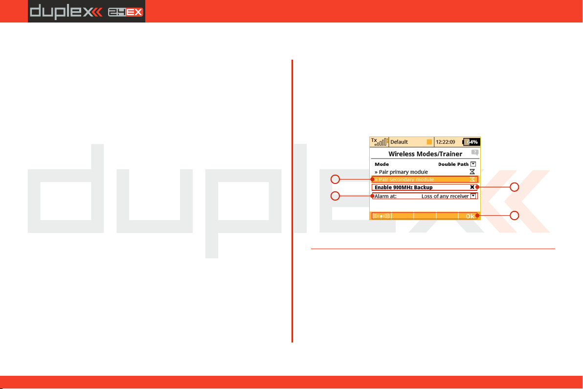
computer radio control system
Trainer Mode with two JETI DS/DC Radios
Make sure that the instructor’s transmitter is bound to the 1.
aircraft in the “Default” wireless mode and that all flying
surfaces are functioning properly.
Change the instructor’s transmitter (DS/DC-14/16/24) wireless 2.
mode to “Teacher” and authorize the secondary TX module to
bind with the student’s transmitter.
Switch ON the student’s transmitter (DS-12), change its wireless 3.
mode to “Student” and allow the instructor’s transmitter to
bind properly. Verify that all of the aircraft’s surfaces are
correctly controlled by the student’s transmitter. If they are not
correct, make the necessary changes in the student’s
transmitter.
EN
Double Path Wireless Mode
a) Mode Selection.
b) Primary module bind control menu line
c) Secondary module bind control menu line
d) Optional signal loss alarm settings.
a
b
c
Trainer Mode for JETI DS-12 as the Instructor Radio
Other brands of transmitters can be used by the student with a JETI
Duplex EX 2.4GHz radio system by using a PPM cable for
communication with DS-12 transmitter.
1. Make sure that the instructor’s transmitter is bound to the
aircraft in the “Default” wireless mode and that all flying
surfaces are functioning properly.
C ha ng e t h e i ns tr u ct or ’s t r an sm it te r m od e t o2.
“Teacher” and connect the PPM signal from the "Student"
transmitter to the DS-12 PPM input (Jack).
Verify that all of the aircraft’s surfaces are correctly controlled by 3.
the student’s transmitter. If they are not correct, make the
necessary changes in the student’s transmitter.
90
d
4. 4.
Page 91

computer radio control system
EN
Signal Loss Alarm Settings
It is possible to define a specific response from the transmitter after
one or more receivers disconnect or lose signal. The options are:
• Loss of any receiver – the alarm is activated every time any of the
receivers loses a connection. This mode is sufficient for applications
where two receivers control separate functions of the model. Both
receivers must be connected for proper function.
• Loss of receiver Rx1 – an alarm is triggered only if the primary Rx
loses connection. This mode is intended for competition pilots who
use the primary Rx in the model while the second receiver is acting as
a reference for the judges. In this mode, the receivers are
independent and you can control your model with only one receiver
connected.
• Loss of receiver Rx2 – an alarm is triggered only if the secondary Rx
loses connection. The intended use and behaviour of this mode is
similar to the previous mode.
• Loss of both receivers – an alarm is triggered after the signal from
both receivers is lost. You should use this option if you want to join
servo signals redundantly using the Enlink plug or any other central
control unit. Both receivers must be connected for proper function.
Pairing the transmitter with receivers in Double Path mode
1. Make sure that receivers are set in Normal mode, not in Clone
mode.
2. Note down which receiver is the first and which is the second
because of later easier identification. Keep the receivers switched
off.
3. Switch on the transmitter with created model, in "Advanced
properties - Wireless modes/Trainer” menu item select "Double
Path mode”.
4. Plug the BIND PLUG interconnection into EXT output of the first
receiver. Switch on the receiver. Now the receiver expects a
sequence for pairing (in case you have Rx firmware version 3.11 and
newer, this period is limited up to 60s).
5. Press „3D pushbutton” on the transmitter over "Pair primary TX
module" command. As soon as the receiver is identified, you will be
asked for confirmation – now push OK button. Switch off the receiver
and remove pairing interconnection.
6. Plug the BIND PLUG interconnection into EXT output of the
second receiver. Switch on the receiver.
7. Press „3D pushbutton” on the transmitter over "Pair secondary
TX module" command. As soon as the receiver is identified, you will
be asked for confirmation – now push OK button. Switch off the
receiver and remove pairing interconnection.
8. Switch on both receivers. The connection should be established
immediately, eventually servo control is allowed.
9. Now you can specify additional parameters of the Double Path
mode so that the transmitter correctly responds to the signal loss
from any of the receivers.
91
4. 4.
Page 92
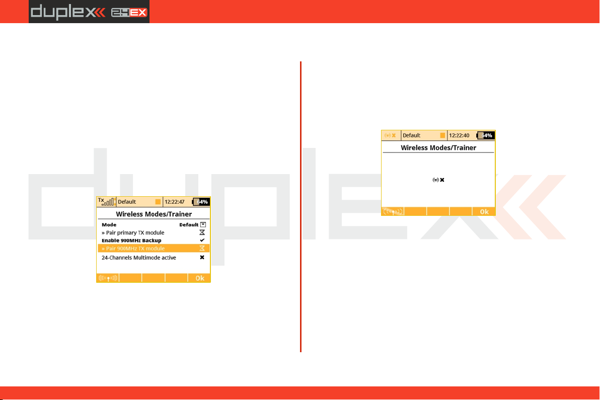
computer radio control system
EN
Using the 900 MHz NG Backup
The backup Tx module can be enabled in all wireless modes to allow
better link redundancy and safety. Just check the Enable 900MHz
Backup. You can bind the 900MHz NG receiver in the same way as
standard Duplex receivers.
1. Insert bind plug to the 900MHz NG receiver
2. Turn on the receiver.
3. Highlight and press the „Pair backup Tx module“ option.
4. If the receiver is found, a sound notification will be played.
It is possible to set an audible alarm that will be triggered in case the
2.4GHz loses link during flight and the backup module takes the
operation (see the System -> System Sounds menu).
(*depends on equipment)
Disable RF Transmission
You can manually disable the wireless transmission by pressing the
"F1 button” followed by a confirmation of the choice. The RF system
turns Off automatically when the USB connection is activated.
Caution: If you disable the transmission with a model attached,
you may cause a signal loss alarm.
92
4. 4.
Page 93
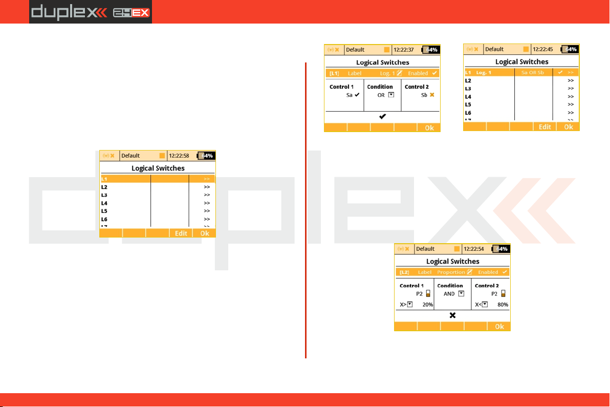
computer radio control system
EN
9.3.4 Logical Switches
If you want to have single or multiple transmitter functions which are
controlled based upon the condition of other control conditions,
then setting up a logical switch is the way to go. Each logical switch is
defined by a logical expression. The logical expression contains a
logical function and the relationship of the other conditions which
must exist for the logical function to be activated. The end result is
that your logical switch can either work like a 2-positon switch
(ON/OFF) or like a proportional 3-position switch (ON/Center/OFF).
1. Creating a Logical Switch
Up to 16 independent logical switches can be created. Select one of
the numbered lines and press the "3D button“ to access the logic
switch setup menu. To enable the switch highlight and change the
enabled value to “Yes”. Once activated you can see the control
inputs and conditions on the menu screen. First set the control
inputs #1 and #2 by assigning functions to switches, sticks or knobs.
After that, select your desired logic statement (OR, YES, Multi). On the
bottom of the screen the result of your logical expression is
displayed by either a check mark or an "X“, depending upon the
current conditon state.
(*depends on equipment)
2. Logical Switch Proportion Calculation
Logical rules can also be created when your logical switch uses
proportional channels. To enable proportional evaluation press the
"F2(Prop)“ button when you select your input controls. When you
allow the use of proportional controls, an additional condition menu
will appear. In this menu the conditions can be set by percentage
value of the channel as well as by the value from which the switch
will be in its full ON/OFF position. Those conditions will then be used
to calculate the logical result.
Example: This figure shows the use of proportional processing by a logical switch. In this
example, if the P2 stick is moved between 20% and 80% of its travel, the logical switch is in the
ON position. If the P2 stick is moved from 0% to 20% or from 80% to 100% then, the logical
switch is in the OFF position. All 16 logical switches can be configured this way if needed.
(number of available logical switches depends on actual transmitter equipment)
93
4. 4.
Page 94
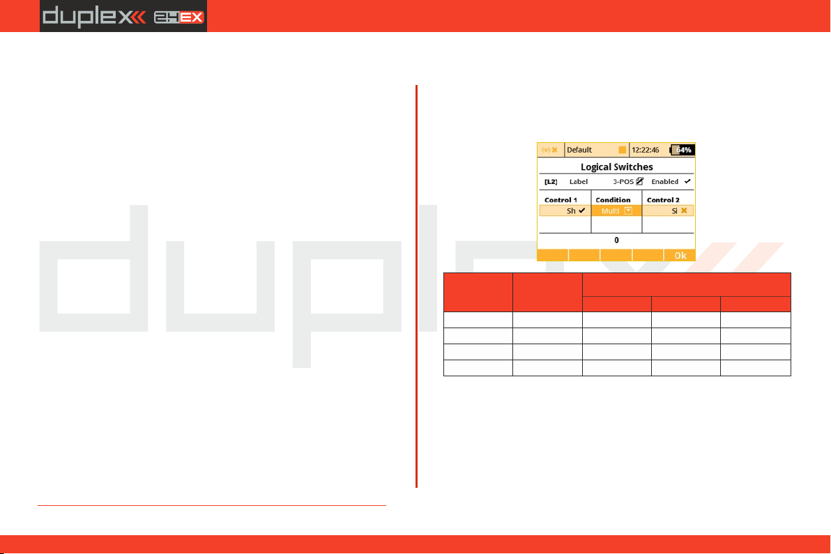
computer radio control system
Switch 1
Switch 2
The result of the operator
ANDORMulti
\\\\\
\]\]#
]\\]#
]]]]]
]]]]
EN
• The AND condition: The resulting value of the switch is
calculated as minimum value from both controls. If you have two
sliders, the first one has +25% and the second one has -25%, the
result returned by the logical switch will then be -25% . (picture )c)
• The OR Condition: The resulting value of the logical switch is
calculated as maximum value from both controls. The higher value
will be returned (picture ). d)
• The Multi condition: This option still emulates a 3-position
switch. The output values of the logical switch are then in range 100%, 0% and 100% (picture ).b)
Example: How to enable or disable the Butterfly function using
a switch.
Many people want to have the ability to turn the Butterfly function
on and off independently from any flight mode. So here we show the
way to do that (see picture ).c)
Select an arbitrary switch as Control 1. In the picture, Sj was 1.
chosen. This switch will overwrite the function of Control 2.
As a Control 2 select a proportional unit that will operate the 2.
Butterfly function (P2 in this example). Make sure it is evaluated
proportionally (see picture ).e)
Control 1 and Control 2 are linked together using AND logical 3.
function. That means, if the switch Sj is deactivated, the operation of
P2 will be blocked. Otherwise, P2 will function normally.
In menu assign the newly created 4. Fine Tuning -> Butterfly
switch L1 in the standard way and try its operation.
4.
3. Emulating a 3-Position Switch
You can use the logic function “Multi” to allow the logic switch to act
as a 3-position switch. The “Multi” logic function can combine the
output from two 2-position switches to create a logic switch with
three output conditions.
4. Using Proportional Logical Switches
The logical switches also offer the option of a complete proportional
evaluation that could be applied to both controls. Just select an
input stick/slider, press the F2 “Prop.” button in the same menu
(picture ) and confirm. Then edit the selection box with options e)
“X<”, “X>”, “Lin” and make sure that you select the “Lin” option
(picture c)). At this point, the logical switch starts to act as a
proportional control.
94
4.
Page 95
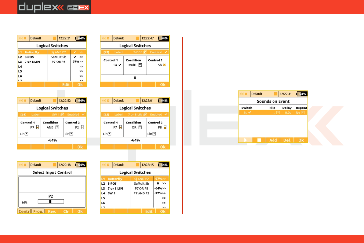
computer radio control system
EN
You can combine more controls using logical conditions:
a)
c)
e)
b)
d)
f)
9.3.5 Sounds on Event (Sound Assignments)
You can assign an audio file to be played based on any transmitter
condition. This means that any music file stored in the transmitter
can be assigned to any switch, stick, knob, logical switch, alarm or
any other special function. Since you can also upload music files the
the DS-12, you can fully customize how your transmitter
communicates with you. If multiple sound files are triggered at the
same time, they will play at the same time and their sounds will
overlay each other.
1. Sound Switch Assignment
Select the “Switch” menu item and assign the switch that you want
to use to trigger the sound playback.
2. Select the Sound File
Select the “File” menu item and select the sound file that you want
assigned to the switch. The available audio files are stored in
Directory/Audio. This is important to remember if you upload your
own files.
3. Sound Playback Delay
The playback of any sound, after activation, can be delayed by
editing the “Delay” menu item.
95
4. 4.
Page 96
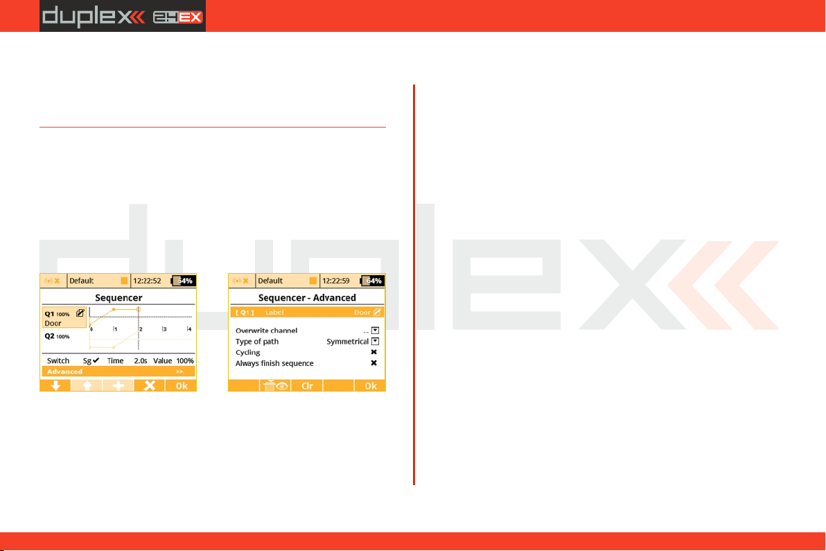
computer radio control system
EN
4. Sound Repeat
This menu item allows you to repeatedly play any sound after it has
been activated. This can be useful if your selected sound’s playing
time is short.
9.3.6 Sequencer
While this function can be used for direct control of landing gear
servos, its usage is almost limitless. Two independent sequences
might be used when you turn the source switch on and off.
You can define up to 6 sequencers Q1-Q6 and within each
sequencer you can define up to 16 control points for each path.
Switching between different sequencers is possible by pressing the
"F1 Down” and "F2 Up” buttons.
a)
To make a sequencer active, you should do the following steps:
Assign a source switch. After this switch is activated, sequencer 1.
starts running. But first it has to know a path that consists of control
points which are distributed over a period of time.
(*depends on equipment)
b)
2. To add control points, you should move the timeline (edit
“Time” column) so that it reaches the desired time. Then press the
"F3 Add” button. The newly created control point will be
highlighted and you can change its value (edit the “Value” column).
Generally said, the point located closest to the timeline is
highlighted and made editable.
You cannot move the control points in a time domain but you 3.
are able to delete any point by pressing „F4 Delete” button.
Now, when you activate the source switch, the timeline begins 4.
moving and the output of the sequencer is updated accordingly. If
you deactivate (turn off ) the switch, the sequencer moves in the
opposite way.
There are some additional options that you can now set in the
Advanced menu:
• You can label the sequencer to simplify identification.
• The option to overwrite a specific channel. Example: If you have
several gear servos installed in your model, here is where you can
define which servo will be directly controlled by the sequencer. Any
other operations (like mixing or DR/Expo) will not be applied to the
output.
• Type of path (Symmetrical / Asymmetrical) – this option tells
the sequencer that there is either one symmetrical path, or there are
two independent paths – one path is used after you activate the
switch and another one after the switch is turned off. If you choose
the Asymmetrical option, the sequence will always start from the
very beginning and it doesn't matter whether the previous
sequence is completed or not. It is recommended to use this option
in conjunction with the Always finish sequence option.
96
4. 4.
Page 97
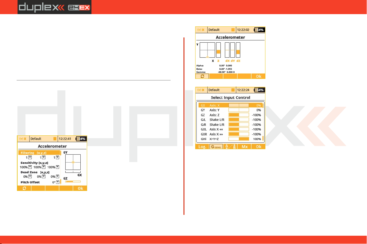
computer radio control system
EN
• Cycling – if you wish a cyclic behaviour for your beacons,
turrets or radar assemblies just check this option.
• Always finish sequence – After checking this option, the
sequencer will never be interrupted and always will travel from the
beginning to the end of its path.
• The button clears all data from the sequencer and „F3 Clr”
resets it to the default state.
9.3.7 Accelerometer
The DS is equipped with an inertial unit that allows you to precisely
determine the orientation of the device in space. This unit consists of
a 3-axis gyroscope, 3-axis accelerometer and additional mathematic
operations. You can freely use this inertial unit to control any
function, trigger any voice announcements or you can simply flip
pages on the main screen.
a)
(*depends on equipment)
You can configure some of the
in e rt ia l u ni t p ar am et e rs i n
A d v a n c e d P r o p e r t i e s - >
Accelerometer. In the picture , a)
the actual orientation of the
transmitter is displayed. The axes
GX, GY, GZ are defined as roll, pitch
and yaw in the same order. The
graph shows the final values after
all corrections have been made.
Within this menu, you can edit
following parameters:
Filtering – This increases
smoothness of the movement for
each axis separately. You can set
values in range from 0 to 10. Zero
value means no filtering and gives
b)
c)
Dead Zone – This means that as the value is increased, the more
you can move the transmitter around the middle position and the
output of the inertial unit will remain zero.
Pitch Offset - This shifts the GY axis so that you don’t have to hold
or keep the transmitter in a completely horizontal position all the
time.
You can also view the raw data coming from accelerometer and
gyroscope by pressing the „F1 button” (see picture ). This might b)
help you to fine tune your setup.
fast reactions. The higher the
filtering setting, the movement
becomes slower and smoother.
Sensitivity – This influences
the gain of the inertial unit for each
axis separately. If you feel that the
reactio n s o f t h e cont ro l l ed
function are too small for the
particular movement, you can
simply increase the corresponding
value of sensitivity, numerically up
to 400%.
4.
97
4.
Page 98
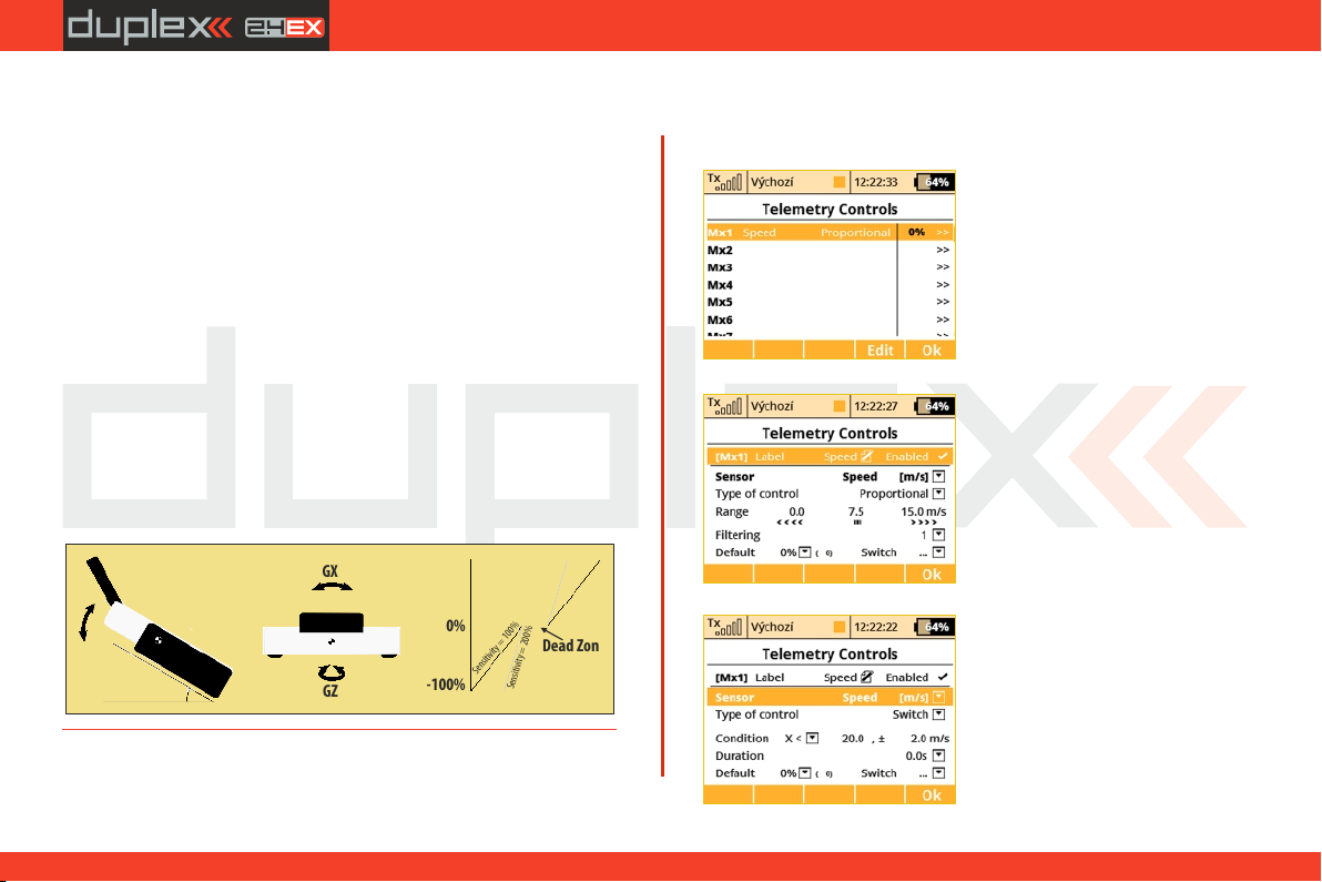
computer radio control system
EN
After you have finished setting the inertial unit itself, you can assign
the resulting variables to any function using a standard input dialog
(picture ). To see the variables of the inertial unit, you have to press c)
the "F2 Gsens.” button. The axes GX, GY, GZ correspond to the graph
shown in the picture ). The last parameters are called Shake L/R a)
and represent a motion gesture. If you quickly shift the transmitter to
the left, the G/L switch will be activated for a short time. Similarly, a
single movement to the right activates the G/R switch. You can use
these gestures to trigger voice announcements, flip pages of the
main screen etc.
The parameters "Axis X<<" and "Axis X>>" represent virtual
twostate switches which are activated when the transmitter is tilted
to the left or to the right along the X-axis.
The "GHi" switch can be used for discuss launch glider (F3K)
detection. It is based on large acceleration and gyroscope readings.
That means, the transmitter is capable of detecting the launch of the
DLG (F3K) model airplane. The "GHi" switch can be assigned to any
function, sequencer or logical switch.
Roll (GX)
100%
0%
Sensitivity = 100%
-100%
-90° 0° 90°
Dead Zone
Sensitivity = 200%
GY
30° Pitch Offset
GX
GZ
9.3.8 Telemetry Controls
Not only can you display telemetry data, record it to your SD card or
(*depends on equipment)
have it voice announced, now it is
possible to control specific model
functions using sensor inputs. This
way, some tasks that previously
required manual adjustment via
visual estimation or alarms can
now be automated.
Up to 8 controls labeled MX1 –
M16 are available, depending on
the type of transmitter and
equipment. Telemetry controls
offer functionality in two modes:
The Switch mode enables you •
to create a virtual two-position
switch using the value of one
telemetry parameter. This switch is
al way s active base d on the
fulfillment of defined logical
conditions.
The Proportional Control mode •
enables you to transform a certain
range of sensor values into a fully
pr oportiona l c ontro l. I t c a n
au tom a tically a nd s moothly
control any kind of function using
telemetry feedback.
4.
98
4.
Page 99
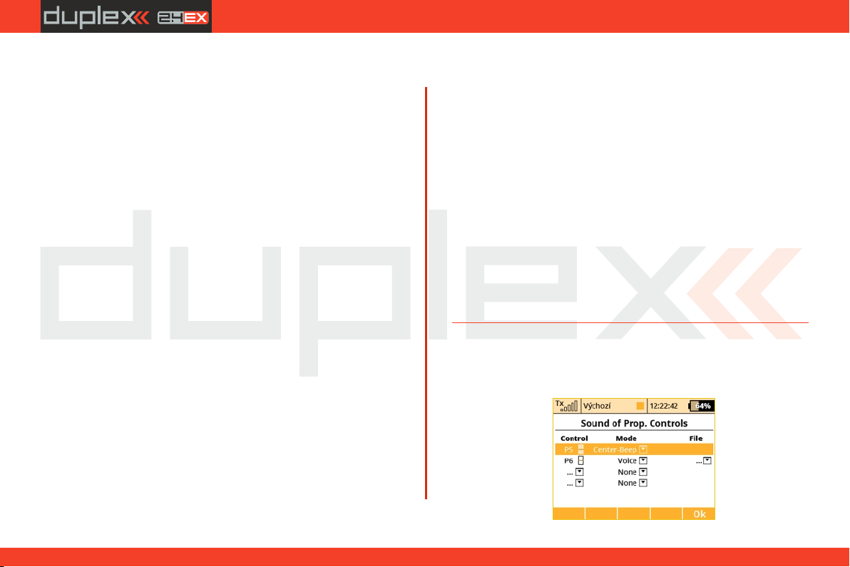
computer radio control system
EN
Examples for the possible use of telemetry controls
If the model speed is less than X m/s, flaps will be raised •
automatically.
If the current is larger than X amperes, the motor run timer starts.•
If the motor temperature is higher than 80 °C, the maximum •
throttle will be limited by the mix.
• If the on-state of the limit switch is detected, the sequencer
automatically starts. (ex. after opening the landing gear doors, the
main gear will be deployed).
Setting the parameters of telemetry controls
Description – Sensor name that will be displayed in the list for easier
orientation.
Active – Tick to enable the telemetry control function.
Sensor – Here you can select a specific telemetry parameter.
Type of control – Select Switch or Proportional control according to
the required functionality.
Condition (X<, X>, X=) – Select the condition under which you want
the control to be active (ie switched on). In the same line, fill in the
numerical value of the decision levels and the hysteresis value
(prefixed with ±). Available in Switch mode.
• Example 1: The entry “X < 20.0m/s ± 2.0m/s” means that
telemetry control switches precisely when the telemetry parameter
value is less than 18 m/s (due to hysteresis of 2 m/s). The control then
symmetrically switches off when the speed exceeds 22 m/s.
• Example 2: The entry “X > 0 ± 0” indicates a switch that is
activated whenever the telemetry value is positive.
Duration – Minimum time of being switched on. If an event takes a
very short time, it is possible to extend the time of the telemetry
control being switched on for the time specified by this parameter.
Available in the Switch mode.
Range – Set the operating range of the sensor (minimum value,
center value, and maximum value). This level will then be
transformed into a proportional range of the control (-100%, 0%,
100%). Available in Proportional Control Mode.
Filtering – Determines the level of received telemetry values
smoothing (filtering). The higher the level of filtration, the smoother
the course, but the response will be slower. Available in Proportional
Control Mode.
Default – The default control value, if the sensor is not present in the
model or the model is not turned on.
Switch – This parameter can specify any switch, which will activate or
deactivate the operation of the telemetry control.
9.3.9 Sound of Proportional Controls
In this menu, you can set a sound notification for up to four
independent controls. You can choose a basic beep in the middle
4.
99
4.
Page 100
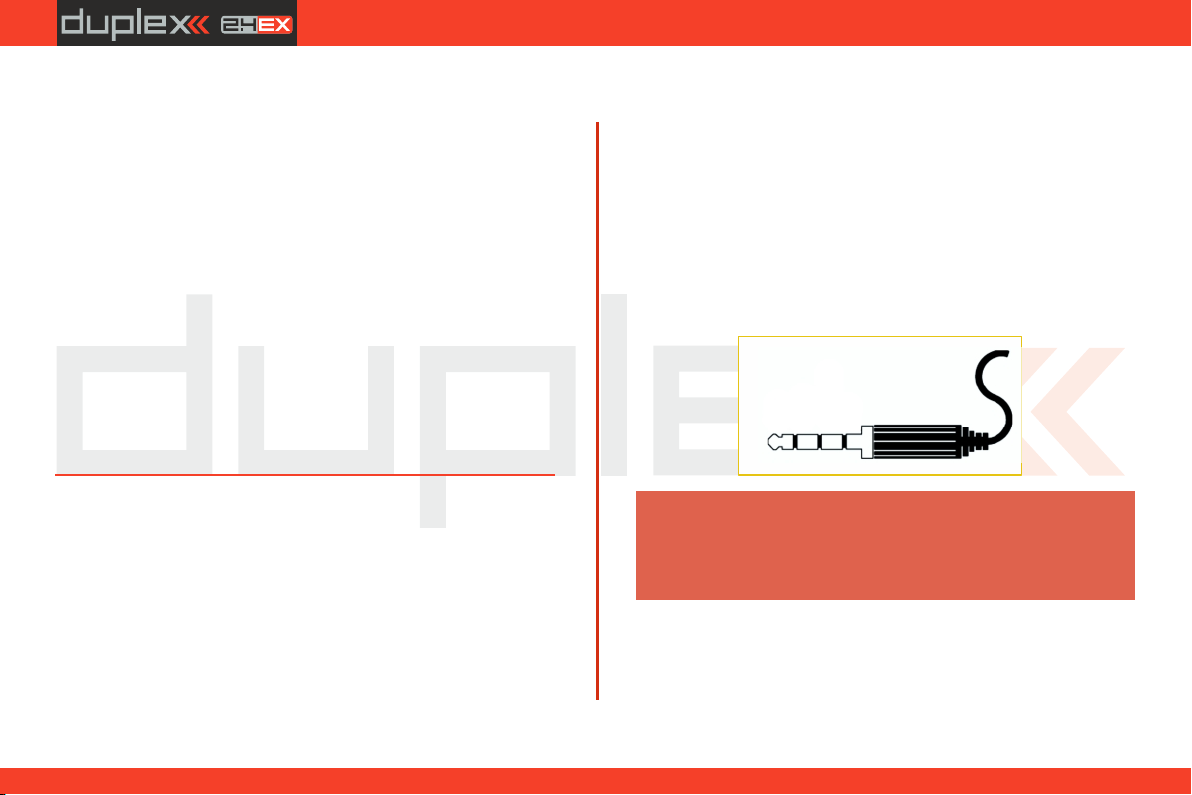
computer radio control system
EN
control position (Center-Beep mode), but voice announcements of
the current position is also available (Voice mode).
• Center-Beep Mode – The transmitter beeps whenever the
control goes to a central position (its deflection is thus 0%).
• Voice Mode – The transmitter will vocally announce the
numeric value of the current position of the control. The value is
reported after every change of the control position and only after
the movement is stopped. In this mode, you can also select an audio
file that will alert you when changes in control positions are
detected.
Example: If you generate the “CONTROL.WAV” file and then assign
it as the File parameter, the transmitter announces eg “Control:
twenty-five”.
The setting is always valid for the current model.
9.3.10 Voice Commands
The Voice commands function has been built in to provide a basic
voice recognition capability so that the pilot can control some
aspects of a model by voice. The voice recognition algorithm doesn’t
contain any predefined language specifications, so you need to
teach it to respond correctly to several phrases of your interest. The
transmitter uses speaker-dependent recognition algorithms and
with the highest accuracy will respond correctly to the same voice as
it has been trained. The DS-12-24 features the voice-activity
detection system (VAD), which is able to detect the presence of
voiced speech in sound samples.
(*depends on equipment)
You can create up to 15 different voice commands (plus a keyphrase)
that are shared between all models. For each model separately it is
possible to specify which commands are active. You can use the
voice commands as a standard control device in the Input selection
dialogue, for example to activate voice telemetry announcements,
play audio files or to switch auxiliary model functions.
It is possible to use the internal microphone or a microphone
connected externally via the 4-pin headphone jack connector. A
standard cellphone headset (Apple or Samsung compatible) should
be used.
Ground
Mic.
Warning
LeftRight
The Voice Commands are still considered experimental
feature. Please do not use this function to control any aspects
of your model that could a cause crash if the command is not
detected properly or another command is erroneously
recognized.
100
4. 4.
 Loading...