

Page 1
MultiControl
Directions for Use
Software version 1.2
oftware version 1.2
Page 2

Table of Contents
1. Introduction . . . . . . . . . . . . . . . . . . . . . . . . . . . . . . . . . . . . . . . . . . . 3
1.1 Safety instructions. . . . . . . . . . . . . . . . . . . . . . . . . . . . . . . . . . . . . . 3
1.2 Installation . . . . . . . . . . . . . . . . . . . . . . . . . . . . . . . . . . . . . . . . . 3
1.3 Controller and power switching unit . . . . . . . . . . . . . . . . . . . . . . . . . . . . 4
1.4 Display . . . . . . . . . . . . . . . . . . . . . . . . . . . . . . . . . . . . . . . . . . . 5
2. Basic Functions . . . . . . . . . . . . . . . . . . . . . . . . . . . . . . . . . . . . . . . . . 6
2.1 Safety shutdown during programming . . . . . . . . . . . . . . . . . . . . . . . . . . . 6
2.2 Function monitoring of external equipment . . . . . . . . . . . . . . . . . . . . . . . . . 6
2.3 Temperature sensor fault recognition . . . . . . . . . . . . . . . . . . . . . . . . . . . . 6
2.4 Self-calibration of temperature sensor. . . . . . . . . . . . . . . . . . . . . . . . . . . . 6
2.5 Interval reset . . . . . . . . . . . . . . . . . . . . . . . . . . . . . . . . . . . . . . . . 6
3. Programmable Functions . . . . . . . . . . . . . . . . . . . . . . . . . . . . . . . . . . . . 6
3.1 Water temperature control . . . . . . . . . . . . . . . . . . . . . . . . . . . . . . . . . 6
3.2 Cooling operation. . . . . . . . . . . . . . . . . . . . . . . . . . . . . . . . . . . . . . 6
3.3 Cooling device control . . . . . . . . . . . . . . . . . . . . . . . . . . . . . . . . . . . 6
3.4 Temperature alarm . . . . . . . . . . . . . . . . . . . . . . . . . . . . . . . . . . . . . 7
3.5 Timing circuit options . . . . . . . . . . . . . . . . . . . . . . . . . . . . . . . . . . . . 7
3.6 pH set point. . . . . . . . . . . . . . . . . . . . . . . . . . . . . . . . . . . . . . . . . 7
3.7 pH alarm . . . . . . . . . . . . . . . . . . . . . . . . . . . . . . . . . . . . . . . . . . 7
3.8 pH electrode calibration . . . . . . . . . . . . . . . . . . . . . . . . . . . . . . . . . . . 7
3.9 Memory function calibration . . . . . . . . . . . . . . . . . . . . . . . . . . . . . . . . 7
3.10 Time . . . . . . . . . . . . . . . . . . . . . . . . . . . . . . . . . . . . . . . . . . . . 7
4. Quick Start Guide to Programming . . . . . . . . . . . . . . . . . . . . . . . . . . . . . . 8
5. Programming Instructions . . . . . . . . . . . . . . . . . . . . . . . . . . . . . . . . . . . 9
5.1 Water temperature control . . . . . . . . . . . . . . . . . . . . . . . . . . . . . . . . . 9
5.2 Switching to cooling operation . . . . . . . . . . . . . . . . . . . . . . . . . . . . . . . 9
5.3 Cooling device control . . . . . . . . . . . . . . . . . . . . . . . . . . . . . . . . . . . 9
5.4 Setting temperature alarm . . . . . . . . . . . . . . . . . . . . . . . . . . . . . . . . 10
5.5 Setting switching times . . . . . . . . . . . . . . . . . . . . . . . . . . . . . . . . . . 10
5.6 Set intervals . . . . . . . . . . . . . . . . . . . . . . . . . . . . . . . . . . . . . . . . 11
5.7 Programming pH set point . . . . . . . . . . . . . . . . . . . . . . . . . . . . . . . . 11
5.8 Setting pH alarm . . . . . . . . . . . . . . . . . . . . . . . . . . . . . . . . . . . . . 12
5.9 Calibrating pH electrode . . . . . . . . . . . . . . . . . . . . . . . . . . . . . . . . . 12
5.10 Setting calibration memory . . . . . . . . . . . . . . . . . . . . . . . . . . . . . . . . 12
5.11 Setting time . . . . . . . . . . . . . . . . . . . . . . . . . . . . . . . . . . . . . . . . 13
6. Manual switching of time-controlled slots . . . . . . . . . . . . . . . . . . . . . . . . . 13
7. Factory Settings . . . . . . . . . . . . . . . . . . . . . . . . . . . . . . . . . . . . . . . 13
8. Reset . . . . . . . . . . . . . . . . . . . . . . . . . . . . . . . . . . . . . . . . . . . . . 14
9. Source of Fault . . . . . . . . . . . . . . . . . . . . . . . . . . . . . . . . . . . . . . . . 14
10. Technical Specifi cations . . . . . . . . . . . . . . . . . . . . . . . . . . . . . . . . . . . . 15
11. EC Declaration of Conformity . . . . . . . . . . . . . . . . . . . . . . . . . . . . . . . . 15
2
Page 3
1. Introduction
m where
ea
ting.
from
All electronic components of the aquarium computer must only be operated in sound condition. If the feeder
is damaged please have this replaced by a technician or send us the equipment for repair. Continued operation
may cause a fatal electric shock. Ensure that the controller (1) and power unit (12) do not come into contact
with water.
It is good practice to disconnect all electrical equipment from the mains before placing your hands in the
aquarium.
Hint: It is recommended to use a separate or dedicated, safety-switch protected supply which disconnects the
mains from the aquarium equipment in the event of an electrical fault.
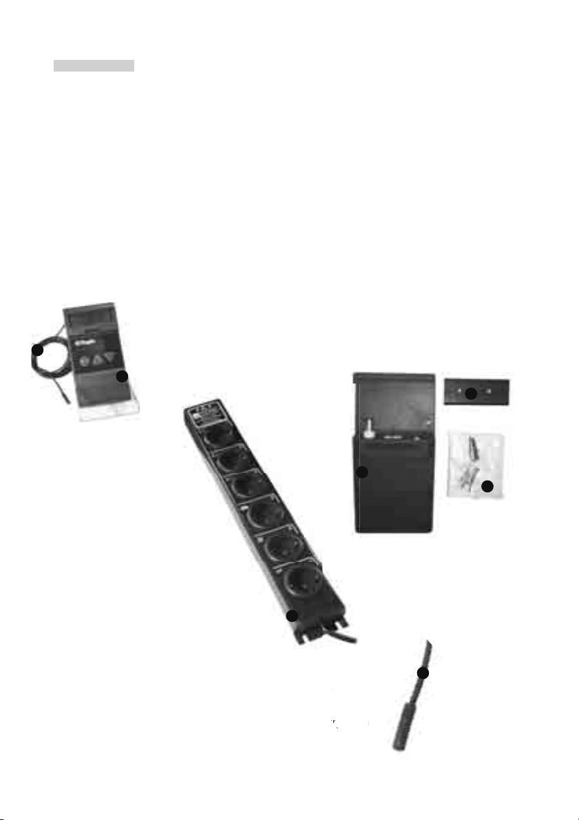
1.2 Installation
Controller
The controller (1) has a mounting recess or slot (2) on the back, which mates with the
mounting rail (3), and may therefore be mounted using the screw set, (4) to a wall or the
11
aquarium cabinet. The 2 metre cable from the Power Unit, provides suffi cient length to
allow positioning of the controller outside the aquarium furniture, so that all values and
1
switch states can be readily viewed.
3
2
Power unit
The Power unit (12) should
be fi xed onto the side of
the aquarium cabinet, to
minimise any chance of
water contact in the event
of a leakage from the
aquarium or fi lter etc.
12
Temperature Sensor
Position the temperature sensor (11) at a place in the aquarium where
there is a good water current. It should not be attached near heating.
Be sure to mount it securely so that it cannot come loose nor emerge from
the water - this could lead to inaccurate displayed values
and overheating of the aquarium.
4
11
3
Page 4
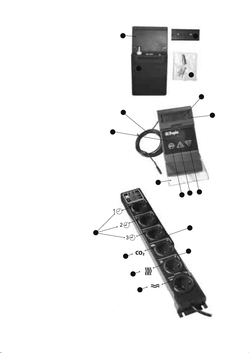
1.3 Controller and Power Unit
l
(1) Controller
1
3
(2) Mounting Slot
(3) Mounting Bar
(4) Screw Set
(5) Display Cover
(6) Display
(7) Keypad Cover
(8) “Menu” Key
(9) ▲ Key
(10) ▼ Key
(11) Temperature Sensor
(12) Power Unit
13
2
4
6
11
1
7
9
8
12
5
10
(13) Power Unit Interval Timer 1, 2, 3
(14) CO
Control Channel
2
(15) Water Temperature Channel
(16) Substrate Temperature / Cooling Channel
e
14
15
16
17
(17) LED
4
Page 5
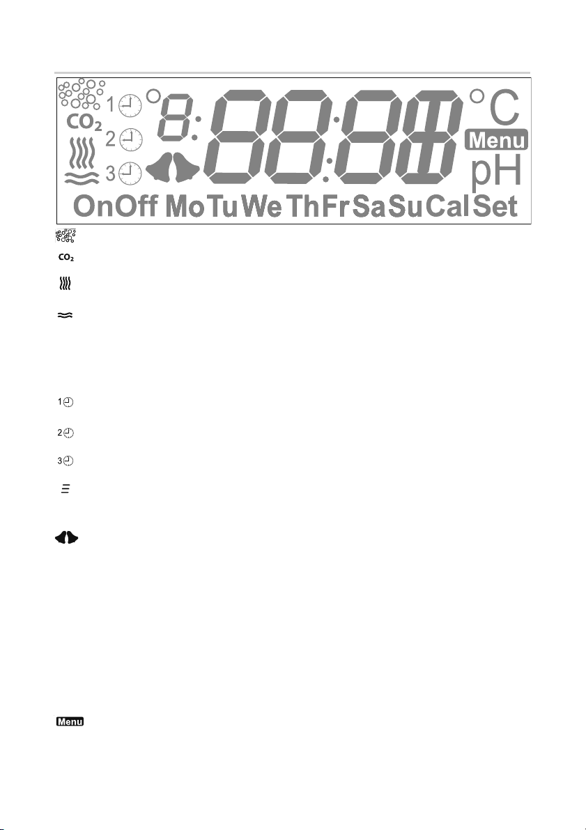
1.4 Display
= Animation effect, appears in association with display of the CO
= Symbol for CO
programming and displaying CO
channel - control of a heating device magnetic valve / appears when
2
channel values
2
symbol
2
= Symbol for heating channel - control of a heating device / appears when programming
and displaying water temperature values
= Symbol for substrate temperature channel or alternatively, cooling channel - control of a substrate
heater or a cooling device / appears when programming and displaying substrate temperature /
cooling values
HEAT = heating / heating function - indicates the “horizontal waves” channel is operating with
a second heating device
COOL = heating /cooling function - indicates the “horizontal waves” channel is operating with a cooling device
= Symbol of the 1
the values of the 1
= Symbol of the 2
the values of the 2
= Symbol of the 3
the values of the 3
st
time-controlled channel / appears when programming and displaying
st
time-controlled channel
nd
time-controlled channel / appears when programming and displaying
nd
time-controlled channel
rd
time-controlled channel / appears when programming and displaying
rd
time-controlled channel
= Symbol for interval timer / displayed when programming time-controlled channels
AUTO/ON/OFF = Automatic mode display, permanent ON, permanent OFF when programming the
time-controlled channels
= appears when programming and displaying the value of the pH alarm, temperature alarm
or the calibration memory function
On / Off = indicates the activation or deactivation of functions
Mo-Su = Display of programmable circuit times / single days Mo-Su, Mo-Fr, Sa-Su / Display of week
days in English
Cal = appears during calibration
Set = appears when entering set point
°8 = shows the number of the switching time when programming
88:88 = Numeric display
E01 = Temperature sensor – cable defect (open circuit)
E02 = Temperature sensor – probe defect (short circuit)
°C = appears when programming and displaying the temperature
= appears when accessing the menu structure
pH = appears when programming and displaying the pH value / appears in connection with
CAL when calibrating the pH electrode
CAL = appears when programming and displaying the calibration memory function
5
Page 6

2. Basic Functions
2.1 Safety shutdown during programming: When entering into programming mode, all slots are deactiva-
ted for safety reasons.
2.2 Function monitoring of external devices: The power unit is fi tted with green LEDs (17). These indicate
the active control of external devices. The three channels for the interval timer can be switched on and off nine
times each, within 24 hours.
2.3 Malfunction and short-circuit recognition of temperature sensor: The temperature sensor (11)
features recognition of sensor malfunction (open or short-circuit), which is displayed with E01 or E02. For
safety, the heater channel ist switched „off“ in this event, so that the aquarium cannot overheat.
If the aquarium is not heated by a Dupla Therm cable heater but an immersion heater, it is recommended to
only use such heaters with integrated thermostat and safety shutdown.
2.4 Self-calibration temperature sensor: The temperature sensor is a precision measuring instrument with a
maximum tolerance of 1%. If replacement is required, calibration is not necessary.
2.5 Interval reset: Irrespective of the time of day, all programmed intervals start when the device is switched
on or the menu is quit.
3. Programmable Functions
3.1 Control of water temperature: Water temperature is controlled with +/- 0.1° C accuracy.
Contact-less switching of the water temperature channel is achieved by use of an electronic triac switch.
The substrate temperature channel can be set within the range of 15° to 35° C. The substrate temperature
channel is automatically preset 0.1° C higher.
Example: You have set the water temperature to 25.0° C. At a measured 25.0° C, the water temperature chan-
nel switches off, however substrate heating continues. If the substrate heating is suffi cient to raise the water
temperature to 25.1° C, then the substrate heating channel also switches off.
Warmth in the substrate strengthens the plant roots, increases the biological activity of the substrate and
creates circulation within the substrate for improved transportation of oxygen and nutrients. The best possible
requirements for healthy plant growth are achieved.
Hint: Immersion heaters with an integrated thermostat should be set 3-4° C higher than the required temperature, so that electronic control via the MultiControl can operate correctly.
3.2 Cooling operation: An inverting function can be enabled to change the substrate heating channel to
a cooling channel. In this way, instead of fl oor heating, an external cooling unit or a cooling fan can be connected to combat the temperature rise in summer.
3.3 Cooling device control: Via the water temperature channel, the immersion heater heats the water up
to the preset temperature. If the temperature then increases more than the preset difference, a cooling device
can be controlled via the substrate temperature channel. When the cooling option is selected, the differential
between heating and cooling can be set as required. The control accuracy is 0.1° C.
Example: If the water temperature is at 25.0° C in COOL operation and the differential to the substrate
heating is 3.0° C, the immersion heater is switched off at 25.0° C. If, due to higher summer temperatures, the
aquarium continues to heat up to 28.0° C due to the summer temperature, cooling is activated.
6
Page 7

3.4 Temperature Alarm: When the water temperature falls below, or exceeds the programmed temperature set-point, an audible and visual temperature alarm is activated. This can be set to mute until the set-point is
reached by pressing the ▲ or ▼ key. The alarm window can be preset between +/- 1° and 5° C. +/-3° C is set as the
factory default. The alarm function can be switched “On“ or “Off”.
By default the function is set to “Off”, to prevent the alarm operating on initial use when the sensor is not yet
positioned in the aquarium and the room temperature is too high or too low.
3.5 Circuit Times: Via 3 time-controlled channels, for example, day and night lighting, circulation pumps or
fi lters can be switched on and off, up to 9 times each, per day. After the 9th programmable switching time,
an interval can be programmed, determining after how many hours/minutes/seconds a circulation or dosing
pump, for example, should switch on for how many hours/minutes/seconds. The interval can be programmed
by the day or by blocks of days. In case of overlaps, the interval function dominates normal switching times. External devices can be programmed daily, Mo-Su, Mo-Fr, Sa-Su. The weekdays are abbreviated on the display.
Alternatively to the weekday, “Off” permanently switches off individual switching times. If all switching times
of the channel are to be switched off permanently, select “OFF” alternatively to “Auto” before entering the
switching times. “ON” switches the channel on permanently. The capacity of the entire Power Unit is
1,500 Watt total. With individual channels having a maximum capacity of 1,000 Watt each.
3.6 pH Set Point: The pH set point can be adjusted within the limits of 4.0 - 9.9. Outside of these limits, the
pH channel is switched off. With the connection of a Dupla pH electrode, the pH level, may be continuously
monitored, and with a Dupla Magnetic Valve also connected to the Multicontrol, pH-controlled CO
may be utilised. Switch hystereris (the difference between the switching point and the triggering point) is 0.1
fertilisation
2
pH, and the control accuracy is +/- 0.1 (reference value). In order to ensure the accuracy of measurement and
therefore the control circuit, the MultiControl provides an optional six-week calibration memory function
CAUTION: If no pH electrode is connected to the MultiControl, so that the BNC socket is open, inevitably, fi ctitious pH values will be displayed in individual as well as toggle mode (where the displayed values change from
one to the next in a 2 second cycle). As a factory default, the display of the pH value is hidden. If you want
them to be displayed, please select “On” when programming the pH point setting.
3.7 pH Alarm: When the programmed pH set-point is either not met or exceeded, there is an acustical and
optical pH alarm. The alarm window can be set between 0.5 and 4.0 pH deviation from the set point. By default, a deviation of pH 0.5 is preset. The alarm function can be enabled or disabled (switched “On” or “Off ”).
The beep can be silenced by pressing the ▲ or ▼ key.
3.8 Calibrate pH Electrode: The factory setting of the calibration points is pH 7 and pH 4, the calibration
sequence fi rst is pH 7, then pH 4. The calibration process can be cancelled by pressing the ▲ and ▼ key simultaneously.
3.9 Calibration Memory Function: With this feature enabled, every six-weeks “CAL” and “pH” fl ashes on
the display as a reminder to check the pH electrode calibration. In order to calibrate the pH electrode, enter
programming mode by pressing the “Menu” key and go to the menu item “CAL” and “pH”.
To disable of the calibration memory function, continue to scroll through the menu items and set the function
to “off”. If you prefer not to carry out a calibration at the moment, the memory display clears after activating
any key and reappears in another 6 weeks.
3.10 Time: The MultiControl has a built-in real-time clock. Changing from summer time to winter time must
be done manually.
7
Page 8

4. Quick Start Guide to Programming
Switch display lighting ‘on’ or ‘off’: Press and hold the ▼ key = on/off.
Toggle mode: Temperature and time of day are displayed alternately
in a 2 second rhythm (factory preset.
Single mode: Optionally either pH value, temperature or time of day are displayed
continuously (by pressing the ▲ and ▼ key).
Hint: Shall the pH value be displayed in the toggle and single mode,
please select “On” when programming the pH set-point in
the menu item.
Changing from toggle to single mode: Press and hold the ▲ key.
Audible acknowledgment: Press key for a moment , i.e. a ‘tap’ = short sound.
Hold key down, i.e. for 2 seconds = long sound.
Switching to programming mode: A) Pressing the “Menu“ key enters the main programming
menu. During programming the symbol
Moving within the menu structure: B) It is possible to scroll through the menu items with the ▲ and
▼ keys (Sequence: Water temperature – HEAT/COOL mode - Difference HEAT/
COOL mode - Temperature alarm - Switching times - pH set-point
- pH alarm - Calibrate pH electrode - Calibration reminder - Time).
Modifying programming: C) Quickly pressing “Menu“ enables the modifi cation of programmed
values, the changeable value fl ashes.
D) Increase or decrease required values with the ▲ and ▼ keys.
E) Acknowledge by activating the “Menu“ key.
For modifi cation of other programmed values continue from step B).
Quitting the programming mode: F) Quitting the programming mode and accessing the operational
mode is done automatically after 3 minutes of inactivity or “Menu“
by holding down the key.
is displayed.
Enter programming menu
Scroll up or down in menu
Enable change in value
Increase or lower value
Acknowledge value change
Press & hold key, to quit programming
and access operating mode
8
Page 9

5. Programming Instructions
First tap “Menu“ key to start the programming mode.
Hint: The symbol Menu indicates you are in the programming mode. By holding down “Menu” it is
possible to quit the programming mode at any time.
5.1 Control of Water Temperature
When pressing the “Menu“ key, “25” fl ashes on the display.
Set the required value with the ▲ or ▼ key.
Acknowledge with “Menu” key, “0” will fl ash.
Set the required value with the ▲ or ▼ key.
Acknowledge with the ”Menu“ key to return to the main menu.
Scroll through to the next menu item with the ▲ key.
5.2 Switch to Cooling Operation
If the alternate cooling operation is not desired, scroll directly to the next menu item by pressing the ▲ key.
Otherwise press the “Menu“ key -”HEAT“ fl ashes.
Change to “COOL“ with the ▲ key
Acknowledge with “Menu“ to return to the main menu.
Scroll through to the next menu item with the ▲ key.
5.3 Control of a Cooling Device
Press the “Menu” key, “3.0” fl ashes.
Set the required value with the ▲ or ▼ key.
Acknowledge with the “Menu“ key to return to the main menu.
Scroll through to the next menu item with the ▲ key.
9
Page 10

5.4 Setting Temperature Alarm
Press “Menu” key, “3.0” will fl ash.
Set the required value with the ▲ or ▼ key.
Acknowledge with “Menu”, “Off” will fl ash.
To activate the temperature alarm, set display to “On” with the ▲ or ▼ key.
Acknowledge with ”Menu“ to return to the main menu.
Scroll to the next menu item with the ▲ key.
5.5 Setting Switching Times
Press the “Menu” key, “Auto” for automatic mode will fl ash.
Press ▲ key, “On” for duration of switch-on time of the slot will fl ash, or press ▼ key and “Off” for duration
of switch-off time of the slot will fl ash. If no duration for switch-on or switch-off time is required, acknowledge
with ““Menu” when “Auto” fl ashes, “1” will fl ash.
Press the “Menu” key to set the switch-on time of the “
Set the desired hour switching-on time with the ▲ or ▼ key.
Acknowledge with “Menu” key, “:00” will fl ash.
Set the desired minutes switching-on time with the ▲ or ▼ key.
Acknowledge with “Menu”, “S-:00“ will fl ash.
Set the desired seconds of switch-on time with the ▲ or ▼ key.
Acknowledge with “Menu”, display “Off” fl ashes, “00:” fl ashes.
Now set switching-off time of slot “
Set the desired hour switching-off time with the ▲ or ▼ key.
Acknowledge with “Menu”, “:00” will fl ash.
Set the desired minutes switching-off time with the ▲ or ▼ key.
Acknowledge with “Menu”, “S-:00“ will fl ash.
Set the desired seconds of switch-off time with the ▲ or ▼ key.
Acknowledge with “Menu”, “MoTuWeThFrSaSu” will fl ash.
Use the ▲ or ▼ key to change day blocks, days or deactivation in the order of „MoTuWeThFr“, „SaSu“,
„Mo“, „Tu“, „We“, „Th“, „Fr“, „Sa“, „Su“, „Off“.
Note: Contrary to “OFF” which permanently switched off the whole channel when selected before programming the switching time, “Off” here only deactivates an individual function.
Acknowledge with “Menu”, “1” will fl ash.
If you want to set (up to 8) other switching on/off times of the slot “
In order to quit sublevels of switching times of “
Scroll through to the next menu item with ▲.
”.
” slot, “00:” will fl ash.
”, press ▲ and program in the same way.
”, hold down “Menu” to return to the main menu.
10
Page 11

5.6 Set intervals
After the 9th programmable switching time, “ “ will fl ash (see 5.5).
Press the “Menu” key to set the spacing of intervals, “00:” will fl ash.
Use the ▲ or ▼ key to specify after how many hours an interval should be activated.
Acknowledge with “Menu”, “:00” will fl ash.
Use the ▲ or ▼ key to specify after how many minutes an interval should be activated. Acknowledge with
“Menu”, “S-:00” will fl ash.
Use the ▲ or ▼ key to specify after how many seconds an interval should be activated. Acknowledge with
“Menu”, “00:” will fl ash.
Use the ▲ or ▼ key to specify how many hours the interval should last.
Acknowledge with “Menu”, “:00” will fl ash.
Use the ▲ or ▼ key to specify how many minutes the interval should last.
Acknowledge with “Menu”, “S-:00” will fl ash.
To quit the sublevel of the switching times, hold down “Menu” to return to the switching menu.
Use the ▲ or ▼ key to change between the time-controlled slots and briefl y press “Menu” to program further
switching times as per 5.5 or intervals as per 5.6.
Hold down “Menu” to leave programming of a time-controlled slot and scroll through to the next menu item
with the ▲ key.
Please note: Irrespective of the time of day, all programmed intervals start when the device is switched on or
the menu is quit. If a precise daytime control is required, set the switching time appropriately, e.g. at 2.30pm
for 5 seconds.
5.7 pH Program Set Point
Press the “Menu” key, “7.0” fl ashes.
Set the required value with the ▲ or ▼ key.
Acknowledge with the “Menu” key, “Off” fl ashes.
Use ▲ or ▼ to set button to “On” to activate pH display in toggle mode.
Note: Acknowledge with “Menu” - “Off” fl ashes. Set to “On” if a pH electrode is connected. If pH electrode is
not connected, leave on “Off” to ensure that open input on controller does not display fi cticious pH values in
normal or toggle mode.
Acknowledge with the ”Menu“ key to return to the main menu.
Scroll to the next menu item with the ▲ key.
11
Page 12

5.8 Setting pH Alarm
Press the “Menu” key, “0.5” fl ashes.
Set the required value with the ▲ or ▼ key.
Acknowledge with “Menu”, “Off” will fl ash.
To activate the pH alarm, set the display to “On” with the ▲ or ▼ key.
Acknowledge with the “Menu” key to return to the main menu.
Scroll through to the next menu item with the ▲ key.
5.9 Calibrating pH Electrode
1. Connect the pH electrode to the MultiControl and remove the protective cap from the electrode tip.
2. Rinse electrode tip briefl y with Dupladest.
3. Press the “Menu” key – “7” appears at the top left of the display.
4. Dip the electrode into the pH 7 solution. When the displayed measurement has settled, press and hold the
“Menu” key (until long beep) to accept value; “7” is displayed.
5. Rinse electrode tip briefl y with Dupladest.
6. Press the “Menu” key – “4” will fl ash. When calibrating the electrode for freshwater aquaria, acknow-
ledge with “Menu”, “4” will stop fl ashing. For saltwater aquaria use the ▲ or ▼ key until “9” fl ashes at
the top and acknowledge with “Menu”, “9” will stop fl ashing.
7. Dip the electrode into the pH 4 solution for freshwater calibration or into the pH 9 solution for saltwater
calibration. When the displayed measurement has settled, press and hold the “Menu” key (until long
beep) to accept value; “4.00” for freshwater calibration or “9.00” for saltwater calibration is displayed.
Press “Menu” to return to the main menu.
8. Rinse electrode tip briefl y with Dupladest.
9. Fix electrode in the aquarium with suction cups.
10. Scroll through to the next menu item with the ▲ key.
The calibration can be interrupted at any time by pressing the ▲ or ▼ key at the same time.
5.10 Setting Calibration Memory
Press “Menu“ key, “On” display fl ashes.
Set key to “Off” with the ▲ or ▼ key to turn off memory function.
Acknowledge with ”Menu“ to return to the main menu.
Scroll through to the next menu item with ▲ key.
12
Page 13

5.11 Setting Time
Press “Menu” key, “00:” fl ashes.
Set the current time in hours with the ▲ or ▼ key.
Acknowledge with “Menu”, “:00” fl ashes.
Set the current time in minutes with the ▲ or ▼ key.
Acknowledge with “Menu”, “Mo” fl ashes.
Set the current week day with the ▲ or ▼ key.
Acknowledge with “Menu” to return to the main menu.
Scroll through to the next menu item with the ▲ key.
To fi nish programming, hold ”Menu“ key down until display changes.
6. Manual switching of time-controlled slots
Press the ▲ and ▼ keys simultaneously, slots 1-3 are shown one above the other.
Press “Menu” to switch slot “
Press ▲ to switch slot “
Press ▼ to switch slot “
After pressing the appropriate key, the device will return to operating mode, manually switched slot will fl ash
as a symbol.
Repeat the process for manual switch-off.
” on or off manually.
” on or off manually.
” on or off manually.
Note: Manual switching immediately dominates normal switching times or interval function. It is automatically
cancelled when programmed switching or intervals are activated. Permanent on or off is set in the programming mode. If no switching times are set in the programming mode, manual switching equates permanent on
or off.
7. Factory Setting
• Target temperature water heating: 25.0° C
• Target temperature substrate heating: 25.1° C
• HEAT/COOL-Modus: HEAT
• Difference heating / cooling differential: 3.0° C
• Temperature Alarm: 3.0° C (off)
• Time switch position 1: Off
• Time switch position 2: Off
• Time switch position 3: Off
• Target pH control: 7.0
• pH Alarm: 0,5 (off)
• Calibration memory function: On
13
Page 14

8. Reset
Should your aquarium computer not be working correctly, please carry out a reset as follows:
1. Switch off power to MultiControl.
2. a) General reset: pull the power plug. Press and hold down the “Menu” key and reconnect power plug.
Release the key. All programmed settings are deleted.
b) Reset the time-controlled slots: pull the power plug. Press and hold down the ▲ key and reconnect
power plug. Release the key. Only programmed settings for the time-controlled slots are deleted,
all other settings are maintained.
3. Release “Menu” key.
Caution: Activating the reset function will result in a loss of all programmed settings.
9. Source of Fault
In the case of a problem, fi rst reset to the factory settings. If this does not solve the problem, please search for
the fault in the following table:
Fault Possible cause Solution
Temperature control is not
working
Immersion heater thermostat
overriding MultiControl
Set heater thermostat 3-4° C higher
than the MultiControl
Display E01
Temperature sensor cable break /
Temperature sensor not connected
Display E02
Alarm cannot be
Temperature sensor hot-wired Replace temperature sensor
Temperature sensor defect Replace temperature sensor
deactivated
External devices are not
Time setting inactive Check time setting and selection of
operated at the preset time
Fluctuating temperature
display
pH value is not displayed
pH value is not controlled
Fluctuating pH value
Temperature sensor cable too close
to a power cable
Display was switched off Switch display on
pH control is not activated Activate pH control
pH electrode cable too close to a
mains cable or a CO
values displayed during calibration
did not steady suffi ciently
If repair is required, please return to where purchased.
14
reactor / the
2
Replace or connect temperature
sensor
week-day
Re-locate temperature sensor
differently
Re-locate pH electrode cable / recalibrate pH electrode - if necessary,
2-3 times
Page 15

10. Technical Specifi cations
Operating voltage: 230 V / 50 Hz
Operating temperature: 0-60° C
Power Unit total load capacity: 1,500 W
Power Unit total fuse rating: 6.3 A/T
Data storage: power failure safe with E-Prom parameter memor
pH Control
pH control range: 4.0 - 9.9
Control accuracy: +/- 0.1 (reference value)
Alarm window: 0.5-4.0
Switching: contact-less, electronic triac
Switching hysteresis: 0.1 pH
Connection power: 1,000 W
Calibration memory: Six-week
Water Temperature
Temperature control range: 15 – 35° C
Control accuracy: +/- 0.1° C
Alarm window: 1.0 – 5.0° C adjustable
Switching: contact-less, electronic triac
Switching hysteresis: 0.1° C
Connection power 1,000 W
Substrate Temperature / Cooling
Switching: contact-less, electronic triac
Differential to water temperature: 1.0 – 5.0° C adjustable
Connection power: 1,000 W
Time-controlled slots
External equipment: user-defi ned
Connection power: 1,000 W
11. EC Declaration of Conformity
The manufacturer declares that the equipment meets the requirements of the applicable EHC standards and
therefore satisfi es the provisions of the EC directives 89/336/EG.
Subject to technical modifi cations.
15
Page 16

Connector plan of recommended
Dupla products
Dohse Aquaristik KG • Otto-Hahn-Str. 9 • D-53501 Gelsdorf
Telefon: 0049-(0)22 25 - 94 15-0 • Fax: 0049-(0)22 25 - 94 64 94
info@dohse-aquaristik.de • www.dupla.com
 Loading...