

Page 1
Gebrauchsanleitung · Instructions for use
Istruzioni d‘uso · Mode d‘emploi
Gebruikshandleiding · Instrucciones de uso
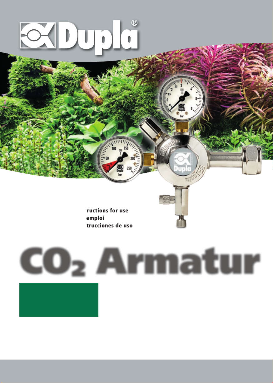
CO
²
Armatur
Pro
Art.-Nr. / Item no. / Codize / Réf. / Art. nr. / Código: 80204
Stand: / Status: / Versione: / Mise à jour: / Stand: / Estado al: 06/2015
Dohse Aquaristik GmbH & Co. KG · 53501 Gelsdorf · Germany · www.dupla.com
1
Page 2
CO² Armatur Pro
Vielen Dank, dass Sie sich für den Kauf der CO
Qualität
und Zuverlässigkeit. Strenge und dauerhafte Qualitätskontrollen sowie Fertigung nach ISO 9001 sorgen für ein Produkt mit hoher
Armatur Pro entschieden haben. Mit der CO² Armatur Pro erhalten Sie ein Produkt höchster
²
Langlebigkeit. Diese Bedienungsanleitung ist Bestandteil des Produktes. Sie enthält wichtige Hinweise zur Inbetriebnahme und Bedienung.
Bewahren Sie die Bedienungsanleitung zum Nachlesen auf.
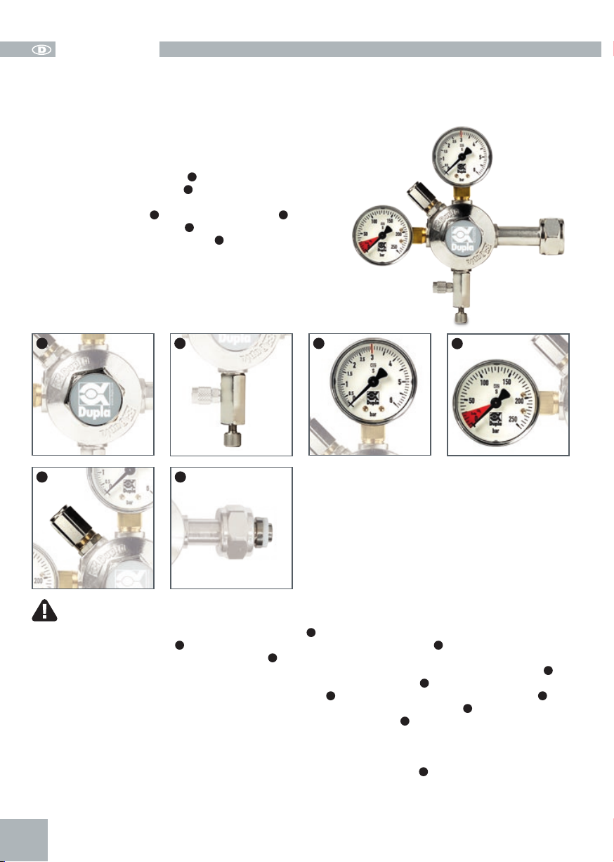
Besondere Merkmale der CO² Armatur Pro:
· hohe Regelgenauigkeit durch Präzisionsdruckminderer
· fein justierbare Arbeitsdruckeinstellung 1
· druckdichtes Präzisionsfeinnadelventil 2 für feinste Einstellungen
der Blasenzahl
· große, gut ablesbare Arbeits- 3 und Flaschendruckmanometer
4
· integriertes Sicherheitsüberdruckventil 5
· verschleißfreie Abdichtung zum Flaschenventil 6
· inkl. integriertem Rückflussventil zum Schutz der CO² Armatur
· korrosionsbeständig durch Materialveredelung
· Feinfilter im Flaschenanschluss und im Feinnadelventil
· für alle CO²-Flaschen mit außenliegendem Flaschenventil
· Niederdruck werksseitig auf 0 bar eingestellt
· optimale Arbeitsdruckeinstellung liegt bei 1 – 1,5 bar
1
5
2
6
3
4
Zur besonderen Beachtung: Depotwechsel und Arbeiten an der CO² Armatur Pro dürfen nur in drucklosem Zustand erfolgen.
Inbetriebnahme: Vergewissern Sie sich, dass das Edelstahlfeinnadelventil 1 vor Anschluss der CO² Armatur Pro an das CO² Depot geschlossen
ist. Stecken Sie den Flaschenanschluss 2 in die Öffnung des Flaschenventils und ziehen die Überwurfmutter 3 handfest an, eventuell mit einem
30 mm Maulschlüssel. Verbinden Sie die Schlauchanschlusstülle 4 der CO² Armatur Pro und dem CO² Reaktor oder CO² Zerstäuber mit einem
CO² festen Schlauch. Öffnen Sie das Flaschenventil vollständig und kontrollieren Sie den CO²-Flaschendruck am Flaschendruckmanometer 5.
Dieser beträgt bei Raumtemperatur ca. 60 bar. Der voreingestellte Arbeitsdruck (Arbeitsdruckmanometer 7) liegt werksseitig bei 0 bar. Beim
erstmaligen Einsatz stellen Sie einen Arbeitsdruck an der Druckverstellschraube 6 von etwa 1 – 1,5 bar ein. Am Arbeitsdruckmanometer 7
können Sie den eingestellten Druck ablesen. Regeln Sie danach mit der Einstellschraube am Edelstahlfeinnadelventil 8 in etwa die von ihnen
gewünschte Blasenzahl ein. Nach ca. 1 Tag (Einlaufphase) können Sie an der Druckverstellschraube 6 die Blasenzahl noch einmal fein nachjustieren. Die Blasenzahl verhält sich proportional zum eingestellten Arbeitsdruck. Haben Sie bei einem Arbeitsdruck von 1 bar eine Blasenzahl
von etwa 10 Blasen pro Minute eingestellt, so können Sie die Blasenzahl einfach verdoppeln, indem Sie den Arbeitsdruck auf 2 bar erhöhen und
eine Verringerung der Blasenzahl um die Hälfte bei Reduzierung des Arbeitsdruck um die Hälfte erreichen. Somit ist eine sehr komfortable und
feinste Blasenzahleinstellung möglich. Zur Verringerung des Arbeitsdruck bitte die Druckverstellschraube
6
gegen den Uhrzeigersinn drehen.
2
Page 3

1
2
3
4
5
6
7 8
Hinweis: Die CO² Armatur Pro ist mit einem integriertem Rückflussventil ausgerüstet, welches sie vor rücklaufendem Wasser schützt.
Technische Daten:
Gasart: CO², Anschluss nach DIN 477 Teil 1 Anschlüsse: Ausgang für CO²-Schlauch
Anschlussnummer: 6 Mikrofilter: 2 Stück eingebaut
Arbeitsdruck: 0 – 3 bar Material: Messing vernickelt
Manometeranschluss: 2 x G 1/4“ Gewicht: ca. 960 g
Ventilspindel: Edelstahl
Abbildungen sind unverbindlich, technische Änderungen vorbehalten.
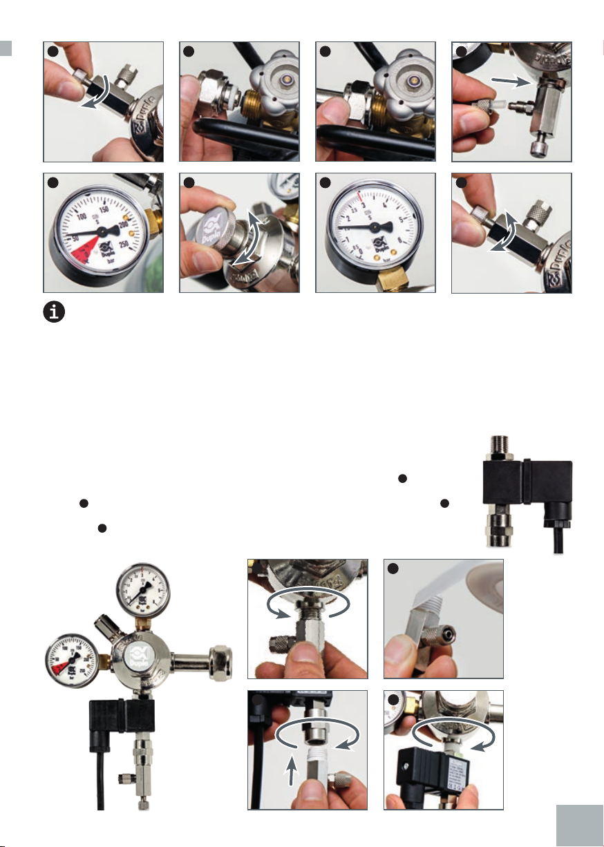
CO² Magnetventil Pro (Art.-Nr. 80243)
Empfehlenswertes Zubehör: Für eine halb- oder vollautomatische Regelung besteht die Nachrüstmöglichkeit
eines CO² Magnetventils Pro. Das CO² Magnetventil Pro wird zwischen CO² Armatur und dem Feinnadelventil geschraubt. Entfernen Sie das Feinnadelventil 1 von der CO² Armatur. Anschließend verbinden Sie das Feinnadelven-
til mit der Verbindungsschraube des CO² Magnetventils Pro 3. Unbedingt vor der Montage die Außengewinde der
Anschlüsse mit 4 – 5 Lagen Teflonband 2 umwickeln (im Lieferumfang enthalten), um eine 100 %-ige Dichtigkeit
zu garantieren. Anschließend drehen Sie nun das fertig montierte CO² Magnetventil Pro in die CO² Armatur 4.
Richten Sie das CO² Magnetventil Pro aus und überprüfen Sie die Schraubverbindungen auf Dichtigkeit!
1
2
3
4
3
Page 4

CO² Armatur Pro
Thank you for choosing to purchase the CO
and reliability. Strict and continual quality checks and manufacture according to ISO 9001 ensure a product with a long service life. These
Armatur Pro. With the CO
²
Armatur Pro you have obtained a product of the highest quality
²
operating instructions are part of the product. They include important information on commissioning and operation. Keep the operating
instructions for future reference.
Special features of the CO² Armatur Pro:
· high control accuracy through precision pressure reducer
· finely adjustable operating pressure setting 1
· pressure-tight fine precision needle valve 2 for high-precision bubble count
setting
· large, easily readable working 3 and cylinder pressure gauge
4
· integrated overpressure safety valve 5
· wear-free seal to the cylinder valve 6
· incl. integrated check valve to protect the CO² fitting
· corrosion-resistant thanks to material finishing
· fine filter in cylinder connection and fine needle valve
· for all CO² cylinders with external cylinder valve
· low pressure has factory setting of 0 bar
· optimum operating pressure setting at 1 – 1.5 bar
1
5
2
6
3
4
Special instructions: Replacing the depot and work on the CO² Armatur Pro must only be carried out when the device is pressureless.
Starting up: Make sure that the stainless steel needle valve 1 is closed before connecting the CO² Armatur Pro to the CO² Depot.
Insert the cylinder connection 2 into the opening of the cylinder valve and tighten the union nut 3 hand-tight, possible using a 30 mm openended spanner. Connect the hose connection spout 4 of the CO² Armatur Pro to the CO² Reactor or CO² Atomiser using a CO² tight hose.
Completely open the cylinder valve and check the CO² cylinder pressure on the cylinder pressure gauge 5. This is around 60 bar at room temperature. The preset operating pressure (operating pressure gauge 7) set by the factory is 0 bar. For initial use, use the pressure adjustment screw 8
to set a operating pressure of around 1 – 1.5 bar. You can read off the set pressure at the operating pressure gauge 7. Then use the adjustment
screw on the stainless steel needle valve 8 to roughly define the desired bubble count. After approx. 1 day (running-in period) you can use
pressure adjustment screw 6 for further fine adjustment of the bubble count. The bubble count is proportional to the defined operating pressure.
If you have set a bubble count of around 10 bubbles per minute at a operating pressure of 1 bar, you can double the bubble count simply by
increasing the operating pressure to 2 bar and halve the bubble count by reducing the operating pressure by half. This allows a convenient and
precise bubble count setting. Turn the pressure adjustment screw 6 anticlockwise to reduce the operating pressure.
4
Page 5
1
2
3
4
5
6
7 8
Note: The CO² Armatur Pro is equipped with an integrated reflux valve that protects the fitting against reflux water.
Technical data:
Gas type:
CO², connection according to DIN 477 Part 1
Connections: output for CO² hose
connection number: 6 Microfilter: 2 units installed
Operating pressure: 0 – 3 bar Material: nickel-plated brass
Pressure gauge connection: 2 x G 1/4“ Weight: approx. 960 g
Valve spindle: stainless stee
Illustrations are non-binding. Technical details are subject to change.
CO² Solenoid Valve Pro (
item no.
80243)
Recommended accessories: For semi-automatic or fully automatic control there is the option to retrofit a CO²
Solenoid Valve Pro. The CO² Solenoid Valve Pro is screwed between the fitting and the needle valve 1.
Remove the
needle valve from the needle valve. Then connect the needle valve to the connecting screw of the CO² Solenoid
Valve Pro 3.
It is essential
that you wrap the outer thread of the connections with 4 – 5 layers of Teflon tape 2
(included in the delivery) to ensure 100 % tightness. Then screw the completely assembled CO² Solenoid Valve Pro
into the fitting 4. Align the CO² Solenoid Valve Pro and check the threaded connections for tightness!
1
2
3
4
5
Page 6

Riduttore CO² Armatur Pro
Vi ringraziamo per esservi orientati verso l‘acquisto del riduttore CO
qualità ed affidabilità. I controlli di qualità rigorosi e permanenti, oltre alla lavorazione conforme allo standard ISO 9001, assicurano un
Armatur Pro. Con CO
²
Armatur Pro avrete un prodotto della massima
²
prodotto di grande durata. Il presente manuale d‘uso è parte integrante del prodotto. Contiene avvertenze importanti relativamente alla
messa in funzione e all‘uso. Si prega di conservare il manuale d‘uso per future consultazioni
Particolari caratteristiche di CO² Armatur Pro:
·
elevata precisione di regolazione grazie al riduttore di pressione di precisione
· pressione d‘esercizio impostabile con microregolazione
1
· valvola stagna a spillo di precisione 2 per le più precise impostazioni
del numero di bolle
· grande manometro ben leggibile per la pressione d‘esercizio 3 e la
pressione della bombola
· valvola integrata di sicurezza da sovrapressioni
4
5
· guarnizione antiusura della valvola della bombola 6
· con valvola antiriflusso integrata a protezione del riduttore di CO
· anticorrosione grazie alla lavorazione del materiale
²
· microfiltro nell‘attacco della bombola e nella valvola a spillo
· per tutte le bombole di CO² con valvola esterna della bombola
· bassa pressione impostata di default su 0 bar
· l‘impostazione ottimale della pressione d‘esercizio è fra 1 – 1,5 bar
1
5
2
6
3
4
N. B.: Il cambio della riserva e gli interventi sul riduttore CO² Armatur Pro si possono effettuare solo in condizioni di depressurizzazione.
Messa in funzione: Sincerarsi che la valvola a spillo in acciaio inox 1 sia chiusa prima dell‘attacco di
riserva
di CO². Inserire l‘attacco della bombola 2 nell‘apertura della valvola della bombola e serrare il dado di raccordo 3 il più saldamente
possibile a mano, eventualmente con una chiave inglese da 30 mm. Collegare la boccola di attacco del tubo flessibile 4 del
Armatur Pro
al reattore CO² Reaktor oppure al diffusore CO² Zerstäuber con un tubo flessibile fisso per la CO². Aprire completamente la
riduttore CO² Armatur Pro
riduttore CO²
alla
valvola della bombola e controllare la pressione della bombola di CO² sull‘apposito manometro 5. Quest‘ultimo indicherà a temperatura
ambiente circa 60 bar. La pressione d‘esercizio preimpostata (manometro della pressione d‘esercizio 7) è posta di default a 0 bar. Al primo
impiego impostare una pressione d‘esercizio con la vite di regolazione pressione 6 di circa 1 – 1,5 bar. Sul manometro della pressione
d‘esercizio 7 si potrà leggere la pressione impostata. Poi, con la vite di regolazione della valvola a spillo in acciaio inox 8 regolare
approssimativamente il numero di bolle desiderato. Dopo circa 1 giorno (fase di assestamento) sarà possibile regolare ancora e con maggior
precisione il numero di bolle con la vite di regolazione pressione 6. Il numero di bolle ha un andamento proporzionale alla pressione
d‘esercizio impostata. Se con una pressione d‘esercizio di 1 bar è stato impostato un numero di bolle pari a circa 10 al minuto, allora sarà
possibile semplicemente raddoppiare il numero di bolle, aumentando la pressione d‘esercizio a 2 bar, mentre si otterrà una diminuzione del
numero di bolle pari alla metà, riducendo la pressione d‘esercizio del 50%. In tal modo è possibile un‘impostazione del numero di bolle
molto comoda e precisa. Per ridurre la pressione d‘esercizio, ruotare in senso antiorario la vite di regolazione pressione 6.
6
Page 7

1
2
3
4
5
6
7 8
Nota: Il riduttore CO² Armatur Pro è attrezzato con una valvola antiriflusso integrata, che protegge CO² Armatur Pro dal riflusso
dell‘acqua.
Dati tecnici:
Tipo di gas: CO², attacco conforme a DIN 477 Parte 1 Attacchi: uscita del tubo flessibile di CO
Numero di attacchi: 6 Microfiltro: 2 unità integrate
Pressione d‘esercizio: 0 – 3 bar Materiale: ottone nichelato
Attacco manometro: 2 x G 1/4“ Peso: circa 960 g
Stelo valvola: acciaio inox
Le illustrazioni non sono vincolanti. Varianti tecniche ammesse.
Elettrovalvola CO² Pro (codize 80243)
Accessori consigliabili: Per una regolazione semiautomatica o completamente automatica si può ricorrere al
retrofitting con l‘elettrovalvola CO² Pro. L‘elettrovalvola CO² Pro si avvita fra il riduttore e la valvola a spillo 1.
Rimuovere la valvola a spillo dal riduttore. Successivamente
dell‘elettrovalvola CO² Pro 3.
con 4 – 5
strati di nastro in teflon 2, per garantire la tenuta al 100 %.
Assolutamente prima del montaggio avvolgere la filettatura esterna degli attacchi
CO² Pro nel riduttore 4. Allineare l‘elettrovalvola CO²
collegare
la valvola a spillo alla vite di collegamento
Poi ruotare l‘elettrovalvola pre-assemblata
Pro e verificare la tenuta stagna dei collegamenti a vite!
1
2
²
3
4
7
Page 8

Détendeur de CO
Pro
²
Merci d’avoir choisi le détendeur de CO² Pro. Le détendeur de CO² Pro est un produit fiable de très haute qualité. Nos produits sont
fabriqués selon la norme ISO 9001 et soumis en continu à des contrôles de qualité rigoureux afin de garantir une grande longévité. Ce mode
d’emploi est partie intégrante du produit. Il contient des conseils importants pour sa mise en service et son utilisation. Conservez-le afin de
pouvoir vous y reporter au besoin.
Caractéristiques du détendeur de
·
grande précision de réglage grâce au détendeur
·
réglage précis de la pression de service
·
vanne à aiguille fine de grande précision et étanche sous pression 2 pour un
CO² Pro:
1
réglage exact du nombre de bulles
·
grands manomètres bien lisibles pour l’affichage de la pression de service
pression de la bouteille
·
vanne de sécurité intégrée pour éviter les surpressions
·
garniture d’étanchéité inusable pour le raccord sur la valve de la bouteille
· clapet anti-retour intégré pour protéger le détendeur de
·
traitement anticorrosion des matériaux
·
filtre fin au niveau du raccord de la bouteille et dans la vanne à aiguille fine
·
compatible avec toutes les bouteilles de
·
basse pression réglée en usine sur 0 bar
4
5
CO
²
CO² munies d’une valve extérieure
· le réglage optimal de la pression de service est compris entre 1 – 1,5 bar
1
5
2
6
3 et de la
6
3
4
Attention: Avant de procéder à un changement de bouteille de
CO² ou de manipuler le détendeur de
CO² Pro, assurez-vous que ce
dernier est bien hors pression.
Mise en service: Assurez-vous que la vanne à aiguille fine
1
est fermée avant de raccorder le détendeur de
CO² Pro à la bouteille de
CO².
Insérez le raccord de la bouteille 2 dans l’ouverture de la valve de la bouteille et serrez à fond l’écrou union 3 en vous aidant au besoin d’une
clé plate de 30 mm. Reliez le raccord fileté du tuyau
d’un tuyau imperméable au
correspondant
5. Cette pression est environ de 60 bar à température ambiante. La pression de service (manomètre
CO². Ouvrez complètement la valve de la bouteille et contrôlez la pression de la bouteille de
0 bar. Lors de la première utilisation, réglez la pression de service sur 1 à 1,5 bar environ à l’aide de la vis de réglage de la pression
pouvez lire la pression réglée sur le manomètre de la pression de service
la vanne à aiguille fine
réglage de la pression
8. Au bout d’une journée (phase de rodage), vous pourrez ajuster à nouveau le nombre de bulles à l’aide de la vis de
6. Le nombre de bulles est proportionnel à la pression de service réglée. Si vous avez réglé le nombre de bulles sur 10
4
du détendeur de
CO² Pro avec le réacteur de
CO² ou le diffuseur de
CO² à l’aide
CO² sur le manomètre
7) est réglée en usine sur
6. Vous
7. Puis réglez le nombre de bulles souhaité à l’aide de la vis située sur
bulles par minute environ pour une pression de service de 1 bar, vous pouvez multiplier par deux le nombre de bulles en augmentant la pression
de service à 2 bar et vous pouvez inversement le diviser par deux en diminuant de moitié la pression de service. Cela permet un réglage aisé
et très précis du nombre de bulles. Pour diminuer la pression de service, tournez la vis de réglage de la pression
6
dans le sens contraire des
aiguilles d’une montre.
8
Page 9

1
2
3
4
5
Remarque: le détendeur de
6
7 8
CO² Pro est équipé d’un clapet anti-retour qui protège la robinetterie du reflux de l’eau.
Caractéristiques techniques:
Type de gaz:
CO², raccordement selon la norme DIN 477-1 Branchements: sortie pour tuyau à
raccord no: 6 Microfiltres: 2 filtres intégrés
Pression de service: 0 – 3 bar Matériau: laiton nickelé
Raccordement du manomètre: 2 x G ¼’’ Poids: environ 960 g
Tige de vanne: inox
lllustations sans engagement de notre part, sous toute réserve de modifications techniques.
Électrovanne CO² Pro (
Accessoires recommandés: Il est possible d’équiper le système d’une électrovanne à
semi-automatique ou entièrement automatique. L’électrovanne
aiguille fine
de l’électrovanne
raccords de 4 à 5 couches de bande en téflon 2 pour garantir une parfaite étanchéité
fournie). Puis vissez l’électrovanne
1. Retirez la vanne à aiguille fine de la robinetterie. Puis reliez cette vanne à la vis de raccordement
CO² Pro 3. Avant de procéder au montage, garnissez impérativement les
réf.
80243)
CO² pour un réglage
CO² Pro se visse entre la robinetterie et la vanne à
filetages mâles des
(la bande en téflon est
CO² Pro ainsi montée sur la robinetterie 4. Ajustez la position de l’électrovanne
CO² Pro et vérifiez que les liaisons vissées sont bien étanches!
1
2
CO
²
3
4
9
Page 10

CO²-Armatuur Pro
Hartelijk dank, dat u besloten heeft om de CO²-armatuur Pro aan te schaffen. Met de CO²-armatuur Pro ontvangt u een product van de
hoogste kwaliteit en betrouwbaarheid. Strenge en permanente kwaliteitscontroles evenals de productie volgens ISO 9001 zorgen voor een
product met een lange levensduur. Deze gebruikshandleiding is bestanddeel van het product. De handleiding bevat belangrijke aanwijzingen
voor de inbedrijfstelling en bediening. Bewaar de gebruikshandleiding om de informatie na te kunnen lezen.
Bijzondere kenmerken van de CO²-armatuur Pro:
· hoge regelnauwkeurigheid door precisiedrukregelaar
· fijn instelbare werkdrukinstelling
· drukvast precisie-fijnnaaldventiel 2 voor de fijnste instellingen van het aantal
belletjes
· grote, goed afleesbare werk- 3 en flesdrukmanometer 4
· geïntegreerd veiligheidsoverdrukventiel
· slijtagevrije afdichting naar het flesventiel
· incl. geïntegreerde terugslagklep ter bescherming van de CO²-armatuur
· corrosiebestendig door materiaalveredeling
· fijnfilter in de flesaansluiting en in het fijnnaaldventiel
· voor alle CO²-flessen met buitenliggend flesventiel
· lage druk fabrieksmatig ingesteld op 0 bar
· optimale werkdrukinstelling ligt bij 1 – 1,5 bar
1
5
6
1
5
2
6
3
4
Let op: Depotwisseling en werkzaamheden aan de CO²-armatuur Pro mogen alleen in drukloze toestand worden uitgevoerd.
Ingebruikneming: Controleer of het roestvrij stalen fijnnaaldventiel 1 voor het aansluiten van de
gesloten is. Steek de flesaansluiting
steeksleutel van 30 mm. Verbind de slangaansluiting 4 van de
2 in de opening van het flesventiel en draai de wartelmoer
CO²-armatuur Pro
en CO²-reactor of CO²-verstuiver met een CO²-vaste
CO²-armatuur Pro
3
handvast aan, eventueel met een
op het CO²-depot
slang. Open het flesventiel volledig en controleer de CO²-flesdruk op de flesdrukmanometer 5. Kamertemperatuur ca. 60 bar. De tevoren
ingestelde werkdruk (werkdrukmanometer 7) ligt fabrieksmatig bij 0 bar. De eerste keer dat het gebruikt wordt, stelt u op de drukinstelschroef 6 een werkdruk van ongeveer 1 – 1,5 bar in. Op de werkdrukmanometer 7kunt u de ingestelde druk aflezen. Regel daarna met de
instelschroef op het roestvrij stalen fijnnaaldventiel 8 bij benadering het door u gewenste aantal belletjes. Na ca. 1 dag (inloopfase) kunt
u op de drukinstelschroef 6 het aantal belletjes nogmaals fijn bijstellen. Het aantal belletjes verhoudt zich proportioneel met de ingestelde
werkdruk. Heeft u bij een werkdruk van 1 bar het aantal bellen ingesteld op ongeveer 10 per minuut dan kunt u het aantal belletjes gewoon
verdubbelen, door de werkdruk tot 2 bar te verhogen en een kunt u om het aantal bellen te verlagen de werkdruk voor de helft reduceren
om de helft van het aantal belletjes te krijgen. Zodoende is een zeer comfortabele en uiterst fijne instelling van het aantal belletjes mogelijk.
Om de werkdruk te verminderen de drukinstelschroef 6 linksom draaien a.u.b.
10
Page 11

1
2
3
4
5
6
7 8
Aanwijzing: De CO²-armatuur Pro is met een geïntegreerde terugslagklep uitgerust, die de CO²-armatuur Pro tegen
terugstromend
water beschermt.
Technische gegevens:
Gassoort: CO², aansluiting conform DIN 477 deel 1 Aansluitingen: uitgang voor CO²-slang
Aansluitnummer 6 Microfilter: 2 stuks ingebouwd
Werkdruk: 0 – 3 bar Materiaal: messing, vernikkeld
Manometeraansluiting: 2 x G 1/4“ Gewicht: ca. 960 g
Klepspil: RVS
Afbeeldingen zijn niet bindend, technische wijzigingen voorbehouden.
CO²-Magneetventiel Pro (
art. nr.
80243)
Aanbevolen accessoires: Voor een half- of volautomatische regeling bestaat de toerustingsmogelijkheid
van een CO²-magneetventiel Pro. Het CO²-magneetventiel Pro wordt tussen de armatuur en het fijnnaaldventiel 1
geschroefd. Verwijder het fijnnaaldventiel van de armatuur. Vervolgens verbindt
met de verbindingsschroef van het CO²-magneetventiel Pro 3. Voor de montage
aansluitingen absoluut met 4 – 5 lagen teflonband
2 omwikkeld worden (bij de levering inbegrepen), om een
u het fijnnaaldventiel
moet de buitendraad van de
100 %-dichtheid te garanderen. Vervolgens draait u nu het klaar gemonteerde CO²-magneetventiel Pro in de
armatuur
4. Richt het CO²-magneetventiel Pro uit en controleer of de schroefverbindingen dicht zijn!
1
2
3
4
11
Page 12

Grifo CO² Pro
Muchas gracias por haberse decidido por la compra del grifo de CO² Pro. Con el grifo de CO² Pro usted obtiene un producto de máxima
calidad y fiabilidad. Unos controles de calidad estrictos y permanentes, así como una fabricación según ISO 9001 ofrecen un producto con
una alta vida útil. Este manual de instrucciones forma parte del producto. Contiene importantes indicaciones acerca de la puesta en servicio
y del manejo. Guarde este manual de instrucciones para futuras consultas.
Características especiales del grifo de
· alta exactitud de regulación mediante regulador de presión de precisión
· ajuste de presión de trabajo finamente ajustable
· válvula de aguja fina de precisión estanca a la presión
CO² Pro:
1
2
para ajustes finos de la
cantidad de burbujas
·
manómetro de presión de trabajo 3 y de la botella 4, grande de fácil lectura
· válvula de sobrepresión de seguridad integrada
· junta con la válvula de la botella
6
exenta de desgaste
· incl. válvula antirreflujo integrada para proteger el grifo de
· resistente contra la corrosión mediante ennoblecimiento del material
5
CO
²
· filtro fino en la conexión de la botella y en la válvula de aguja fina
· para todas las botellas de
CO² con válvula de la botella externa
· baja presión ajustada de fábrica a 0
· el ajuste de la presión de trabajo óptimo se encuentra entre 1 – 1,5 bar
1
5
2
6
3
4
Para tener especialmente en cuenta: El cambio del depósito y los trabajos en el grifo de
CO² Pro sólo se deben realizar en un
estado sin presión.
Puesta en marcha: Asegúrese antes de conectar el grifo de
1
está cerrada. Inserte la conexión de la botella 2 en la apertura de la válvula de la botella y apriete la tuerca de unión 3 con la
eventualmente con una llave fija de 30 mm. Conecte la boquilla de conexión de la manguera 4 del
del atomizador de
manómetro de presión de la botella
metro de presión de trabajo
de presión
CO² con una manguera fija de
5. A temperatura ambiente, ésta es de aprox. 60 bar. La presión de trabajo preajustada de fábrica (manó-
7) es de 0 bar. Al aplicar por primera vez ajuste una presión de trabajo de aprox. 1 – 1,5 bar en el tornillo de ajuste
6.
En el manómetro de presión de trabajo
CO². Abra la válvula de la botella por completo y controle la presión de la botella de
de burbujas deseada en la válvula de aguja fina de acero inoxidable con el tornillo de ajuste
puede reajustar con precisión otra vez la cantidad de burbujas en el tornillo de ajuste de presión
CO² Pro al depósito de
CO², que la válvula de aguja fina de acero inoxidable
mano,
grifo de
CO² Pro
y del reactor
de
CO² o
CO² en el
7usted puede leer la presión ajustada. Regule después aproximadamente la cantidad
8. Después de aprox. 1 día (fase de rodaje) usted
6. La cantidad de burbujas se comporta de
forma proporcional con respecto a la presión de trabajo ajustada. Si con una presión de trabajo de 1 bar usted ha ajustado una cantidad de
burbujas de aprox. 10 burbujas por minuto, podrá duplicar simplemente la cantidad de burbujas aumentando la presión de trabajo a 2 bar, así
como disminuir ésta a la mitad reduciendo la presión de trabajo a la mitad. De esta manera es posible un ajuste confortable y fino de la cantidad
de burbujas. Para reducir la presión de trabajo por favor girar el tornillo de ajuste de presión
6
contra el sentido de las agujas del reloj.
12
Page 13

1
2
3
4
5
6
7 8
Nota: El grifo de CO² Pro está equipado con una válvula antirreflujo integrada, que no permite el retorno de agua para proteger el
grifo de
CO² Pro.
Datos técnicos:
Tipo de gas:
CO², conexión según DIN 477 parte 1 Conexiones: salida para manguera de
Número de conexión: 6 Microfiltro: montadas 2 piezas
Presión de trabajo: 0 – 3 bar Material: latón niquelado
Conexión de manómetro:
2 x G 1/4“
Peso: aprox. 960 g
Husillo de la válvula: acero inoxidable
Las ilustraciones no son vinculantes, reservado el derecho de introducir modificaciones técnicas.
Válvula magnética de CO² Pro (
código
80243)
Accesorio recomendado: Para una regulación semi o completamente automática existe la posibilidad de equipar posteriormente una válvula magnética de
y la válvula de aguja fina
1. Extraiga la válvula de aguja fina del grifo. A continuación conecte la válvula de aguja
fina con el tornillo de unión de la válvula magnética de
exteriores de las conexiones con 4 – 5 capas de cinta de teflón 2
estanqueidad del 100 %. A continuación enrosque la válvula magnética de CO² Pro acabada en el grifo 4. ¡Oriente
la válvula magnética de
CO² Pro y compruebe la estanqueidad de las uniones roscadas!
CO² Pro. La válvula magnética de
CO² Pro se atornilla entre el grifo
CO² Pro 3. Antes del montaje envolver sin falta las roscas
(incluida en el suministro), para garantizar una
1
2
CO
²
3
4
13
Page 14

Dazu empfehlen wir: / Recommended Supplement: / Si consiglia di: / Nous recommandons: / Wij raden ook aan: / Recomendamos:
Plant 24
CO² Volldünger für Nanoaquarien
CO² Compound Fertilizer for Nano Aquaria
CO² fertilizzante completo per nano acquari
Engrais complet CO² pour nano aquariums
CO² volledige meststof voor nano aquaria
Fertilizante completo CO² para nanoacuarios
Art.-Nr. / Item no. # 80336
Plant basic
Basisdünger
Basic Fertilizer
Fertilizzante di base
Engrais de base
Basisbemesting
Abono básico
10 ml · Art.-Nr. / Item no. # 80300
50 ml · Art.-Nr. / Item no. # 80305
pH-Elektroden Set · pH Electrode Set
Set elettrodi per pH · Jeu d‘électrodes pH
pH-elektroden-set · Set de electrodos para pH
Hochwertige pH-Glaselektrode mit Kalibrier lösungen. Laborqualität.
High-quality pH glass electrode with calibration Laboratory quality.
Di alta qualità in vetro elettrodo pH soluzioni per la taratura. Qualità del laboratorio.
Electrodes en verre pH de haute qualité. Qualité labo.
Hoogwaardige pH-glaselektrode met kalibreeroplossingen. Laboratoriumkwaliteit.
Electrodo de cristal para pH de alta calidad con líquidos de calibración. Calidad de laboratorio.
Art.-Nr. / Item no. # 80290
Plant 24
Tagesdünger
Daily Fertilizer
Fertilizzante giornalier
Engrais journalier
Dagelijkse bemesting
Abono diario
10 ml · Art.-Nr. / Item no. # 80310
50 ml · Art.-Nr. / Item no. # 80315
14
Page 15

Scaper´s Juice Eisen 24
Eisendünger
Iron Fertilizer
Fertilizzante ferro
Engrais fer
Ijzerbemesting
Fertilización con hierro
10 ml · Art.-Nr. / Item no. # 80000
50 ml · Art.-Nr. / Item no. # 80002
Scaper´s Juice Kalium 24
Kaliumdünger
Potassium Fertilizer
Fertilizzante di potassio
Engrais de potassium
Kaliummeststof
Fertilizantes de potasio
10 ml · Art.-Nr. / Item no. # 80004
50 ml · Art.-Nr. / Item no. # 80006
pH-Control
Microprozessorgesteuertes pH-Regelgerät mit Timerfunktion
Microprocessor-Regulated pH Control Device with Timer Function
Regolatore di pH con comando a micro processore e funzione timer
Régulateur de pH à double circuit, commandé par microprocesseur,
avec fonction minuterie
Microprocessorgestuurde pH-regelaar met timerfunctie
Aparato de regulación de pH con función de temporizador
controlado por micro procesador
Art.-Nr. / Item no. # 80286
Scaper´s Juice N/P 24
Nitrat-/Phosphatdünger
Nitrogen/Phosphate Fertilizer
Nitrato/Fosfatici fertilizzanti
Nitrate/Engrais phosphatés
Nitraat/Fosfaat Fertilizer
Nitrato/Fosfato de los fertilizantes
10 ml · Art.-Nr. / Item no. # 80008
50 ml · Art.-Nr. / Item no. # 80010
15
Page 16

Dohse Aquaristik GmbH & Co. KG
Otto-Hahn-Str. 9
53501 Gelsdorf · Germany
Telefon: +49 2225 94150
E-Mail: info@dohse-aquaristik.de
Internet: www.dupla.com
 Loading...