

Duotraq DQ75 Quick Start Manual
DQ75 INSTALLATION GUIDE
OCT 2016 V.1
DQ75 Quick start Guide
General Description
The DQ75 is a compact tracking device with built-in GPS & GSM antennas. It has a waterproof (IP67) case which
houses an 1100 mAh Li-polymer back-up battery. Standby time without reporting is 280 hours, with 175 hours
at 10-minute tracking intervals. Its main application is tracking vehicles, trailers, boats & other assets using the
online software. For anti-theft applications, the unit can be mounted on any flat surface facing the sky. Internal
placement is possible inside cabins, equipment consoles and boat lockers, providing the internal GPS antennas
are not blocked by large metallic surfaces. In each case it is best to test the unit in place fixed temporarily with
Velcro or similar on a short journey before connecting the power cable. More permanent fixing of the housing
can be made using the screw fixing lug, ‘VHB’ adhesive tape or cable ties. Ensure that the power cables are
routed away from moving parts, and the serial number label is on the base, with the blank cover facing the sky.
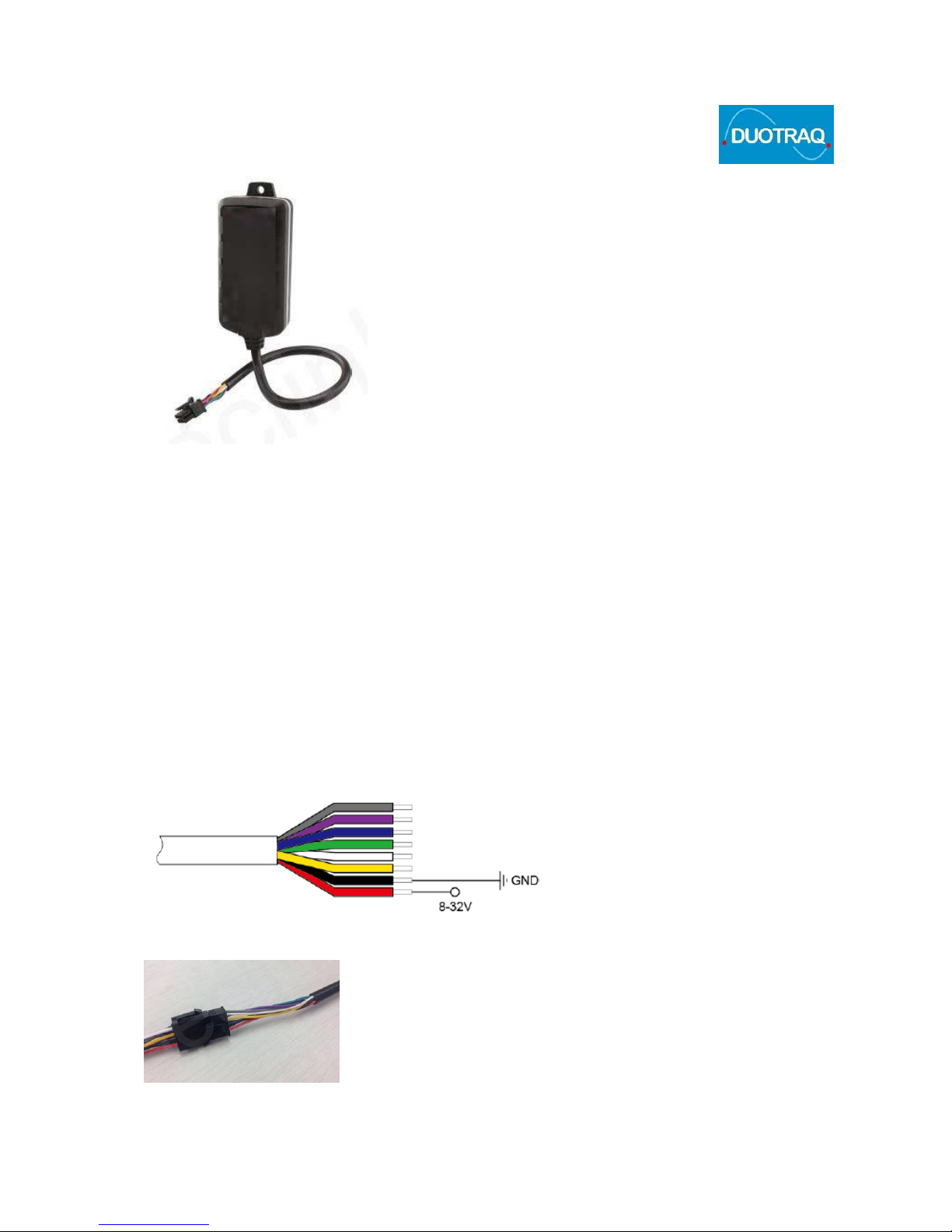
Cable Connections
DQ75 is supplied with an 8-Pin Molex connector which is used for configuration, plus an extension lead with
bare ends. The Molex can be cut off to connect the wires directly, or plugged to the cable extension. Use
waterproof tape or shrink-wrap sleeves if installing in a wet environment, such as boats or Jetskis.
Connect an 8-32 VDC external power source with Red (+) positive and Black (-) ground connections. This will
switch on the device & charge the internal battery.
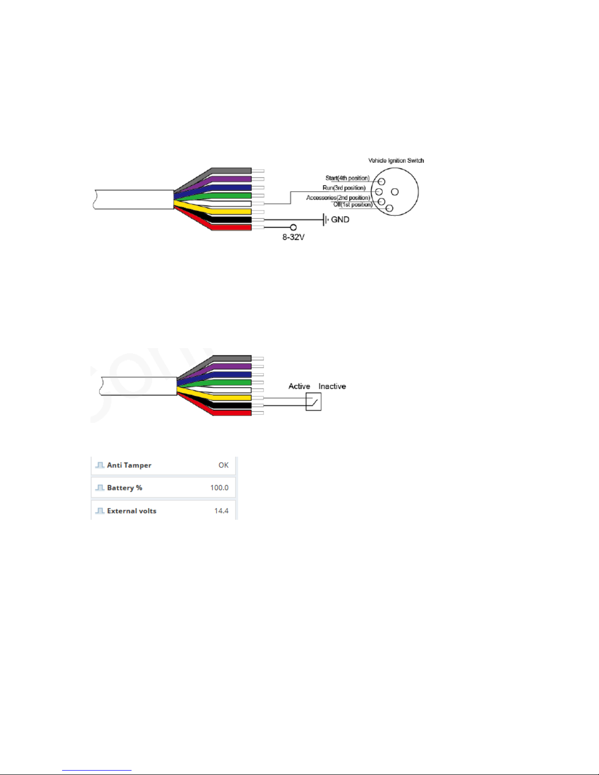
Ignition
An additional positive ignition wire (White) can be connected to indicate engine status. This is used to log
accumulated ‘engine hours’ for service intervals & maintenance purposes. The ignition signal creates trip
start/stop indications. Note that even if the ignition wire is not connected, the device map label will still
indicate ignition ‘active’ when movement is sensed.
Anti-Tamper
The yellow wire is a negative digital input configured as a ‘normally closed’ loop. This should be connected to
the supply negative (black wire). A loop between the two terminals can be extended to attach to items like
Outboard Motors on boats. If the wire is cut by removing the motor, an immediate ‘anti-tamper’ alarm will be
generated. When the loop is closed, the map label will show ‘OK’
External Power
When connected to an external power source such as a vehicle/boat battery, the supply voltage will be
indicated with each tracking report received, so can be used to monitor levels in real time. An alert can be set
to a threshold of your own choosing. ‘Power disconnect’ alerts may be used to indicate the tracker has been
removed during a theft attempt, in addition to anti-tamper messages.
Device Status LEDs
 Loading...