

Duo-Therm 600308.001, 600308.002, 600312.001, 600315.001 Installation & Operating Instructions Manual
INSTALLATIO
N
&
OPERATING INSTRUCTIONS
b
ROOF MOUNT
MODELS
AIR
CONDITIONER
600308.001
600308.002
60031 2.001
60031 5.001
PATENT
No.
4641502
Ad
Pre-Wired For Optional Heat Package
UNDERWRITERS
LABORATORIES
LISTED
1N6,
@
WARNING
THIS UNIT MUST BE SERVICED BY
AN AUTHORIZED SERVICEMAN.
MODIFICATION OF ME APPLIANCE
BE
EXTREMELY HAZARDOUS
CAN
AND COULD LEAD TO SERIOUS
INJURY OR DEATH.
-IMPORTANT INSTRUCTIONSMUST STAY WITH UNIT
I
OWNER-R EAD CAREFULLY
Form No.191411.006 4/87
0
1987
The Danetic Cap.
DUO-THERM
I
Cet apparei I doit etre repare seulement
parun reparatwr autorise. Modification
I'appareil pourrai t etreextremement
de
dangereuse, et pout~ait causenalou
AVIS:
LaGrange, Indiana
46761
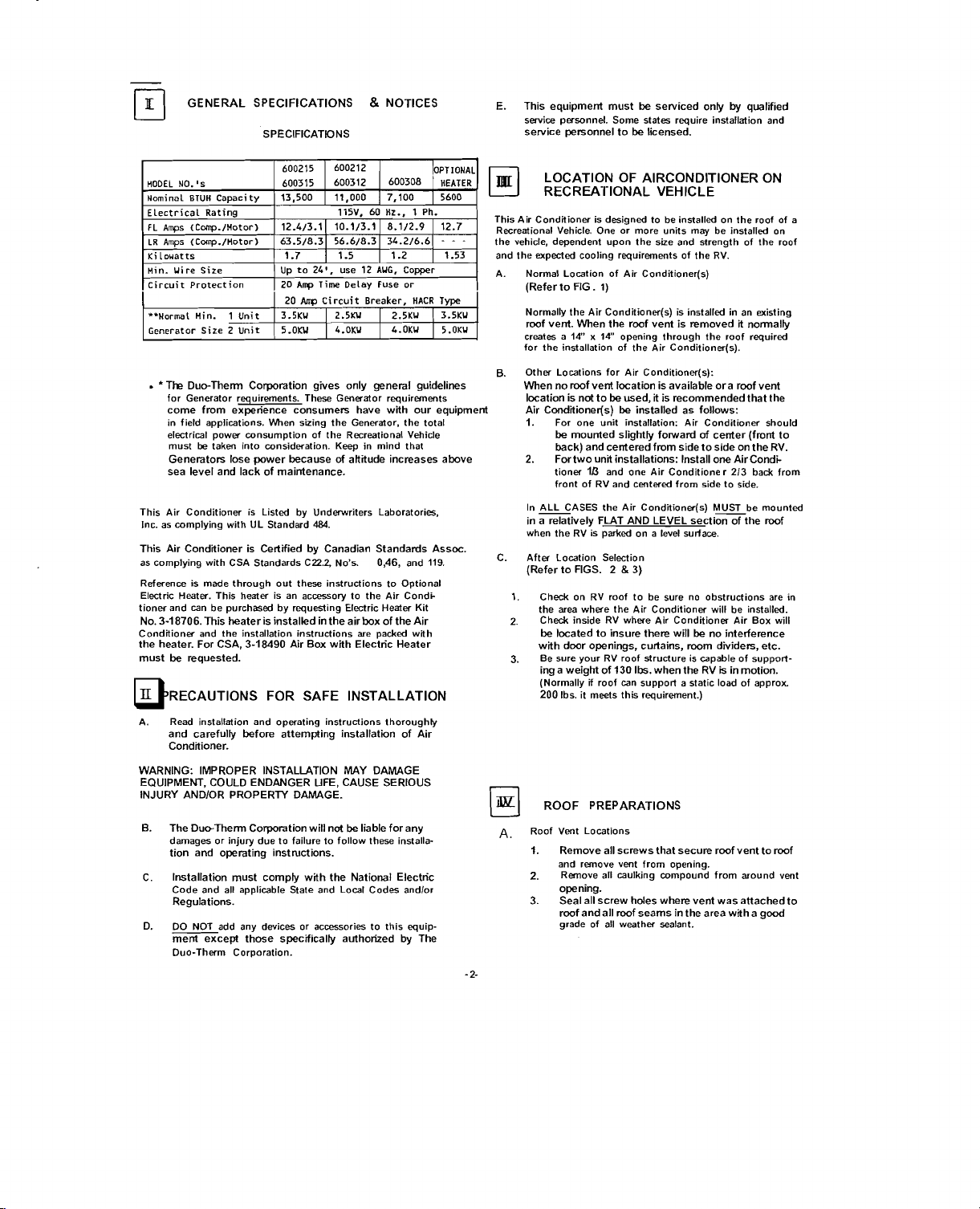
GENERAL SPECIFICATIONS
SPECIFICATDNS
8
NOTICES E. This equipment must be Serviced only
service personnel. Some states require installation and
service personnel to be licensed.
by
qualified
1
600312
1
1
HODEL
NO.'s
Nominal
RTUH
Electrical Rating
LR
Amps (Cmp./Hotor) 63.5/8.3 56.6/8.3 34.2/6.6
Ki
Lowatts
uin. Uire Size
Circuit Protection
**Normal Win. 1 Unit 1 3.5KU 1 2.5KU I 2.5KU ( 3.5KU
1
Generator Size
.
'Tha Duc-Them Corporation gives only general guidelines
for Generator requirements. These Generator requirements
come from experience consumers have with our equipment
in field applications. When sizing the Generator, the total
electrical power consumption of the Recreational Vehicle
sea level and lack of maintenance.
This Air Conditioner is Listed by Underwriters Laboratories,
Inc. as complying wilh
This Air Conditioner is Certified by Canadian Standards Assoc.
as complying with CSA Standards C22.2, No's.
Reference is made through out these instructions to Optional
Electric Heater. This heater is an accessory to the Air
tionw and can be purchased by requesting Electric Heater Kit
No.
3-18706.
Conditioner and the installation instructions are packed with
the heater. For CSA,
must be requested.
A. Read installation and operating instructions thoroughly
WARNING: IMPROPER INSTALLATION MAY DAMAGE
EQUIPMEM. COULD ENDANGER UFE, CAUSE SERIOUS
INJURY
0.
C.
D. DO NOT add any devices or accessories to this equip-
Capacity 113,500
tinit
be
taken into consideration. Keep in mind that
must
Generator; lose power because of attitude increases above
This heater is installed in the air box of the Air
and carefully before attempting installation of Air
Conditioner.
AND/OR PROPERTY DAMAGE.
The Duc-Them Corporation will not be liable for any
damages or injury due to failure to follow these installation and operating instructions.
Installation must comply with the National Electric
Code and all applicable State and Local Codes
Regulations.
ment except those specifically authorized
Duo-Therm Corporation.
600315
UD
I20
1
20
1
5.OKU 1 4.OKU
UL Standard
3-18490
1
11,000 1 7,100
115V. 60 Hz., 1 Ph.
to 24'. use
Amp
Time Delay Fuse or
Amp
Circuit Breaker, HACR
484.
Air
Box with Electric Heater
600308 1 HEATER
12
AUG. Comer
.
I
L.OKU I 5.OKU
046,
Condk
andlor
by
..
and
The
1
119.
5600
- - -
Type
LOCATION OF AIRCONDITIONER ON
RECREATIONAL VEHICLE
This Air Conditioner is designed to be installed on the roof of a
Recreational Vehicle. One or more units may be installed on
the vehicle, dependent upon the size and strength of the roof
and the expected cooling requirements of the RV.
A. Normal Location of Air
(Refer to FIG. 1)
Normally the Air Conditioner(s) is installed in an existing
I
roof vent. When the roof vent is removed it normally
14"
creates a
for the installation of the Air
Other Locations for Air Conditioner(s):
B.
When no roof vent location is available ora roof vent
location is not to be used, it is recommended that the
Air
1.
2.
In
9ASES the Air Conditioner(s) Mxbe mounted
in a relatively FLAT AND LEVEL section of the
when the RV is parked on a level surface.
C. After Lowtion Selection
[Refer to FIGS.
Check on RV roof to be sure no obstructions are in
1.
the area where the Air Conditioner will be installed.
Check inside RV where Air Conditioner Air Box will
2.
be located to insure there will be no interference
with door openings, curtains, mom dividers, etc.
3.
Be sure your RV roof structure is
ing a weight of
(Normally roof can support a static load of approx
200
A,
Roof Vent Locations
1.
2.
3.
x 14'' opening through the roof required
Condltioner(s) be installed as follows:
For one unit installation: Air Conditioner should
be mounted slightly
back) and centered from side to side on the RV.
Fortwo unlt installations: Install one AirCondi-
tioner
l/3
front of RV and centered from side to side.
Ibs. it meets this requirement.)
ROOF PREPARATIONS
Remove all screws that secure roof vent to roof
and remove vent from opening.
Remove all caulking compound from around vent
opening.
Seal all screw hdes where vent was attached to
roof
andall mof seams in the area with a good
grade of all
Conditioner(s)
Conditioner(s).
folward
of
center (front to
and one Air Conditioner
2 & 3)
130
Ibs. when the RV
wealher sealant.
capable of support-
213
is
in motion.
back from
mof

B. Other
CAUTION: Disconnect all
CAUTION:
C.
Than Rod Verd
(Refer
to
FIG.4)
dh
than a rod vent locatim fa
If
er(s) was select& a
he roofand ceiling ofhe RV. ltis recumndedthat
ttr's opening
ben
connect
battery before performing any cutting on the
RV surface. FAILURE TO
INSTRUCTION MAY CREATE A SHOCK
HAZARD.
Mark 14" x 14" opening on roof of RV with
I.
marker.
Carefully cut opening in roof of RV
2.
There may be electrical wiring located between
roof and ceiling.
Carefully cut a
3.
of the RV.
Opening Preparations (Refer to FIG. 4)
If
the opening exceed s 141/2# 141/2"it will be
I.
necessary to make the opening smaller by installing spacers or close off plates.
2.
If
the opening is smaller than 14" x
be necessary to enlarge the opening.
Route a grounded power supply line from circuit
3.
breaker or fuse box to the roof opening.
a.
b.
c. The power supply wirin g MUST comply with
d. Depending on entrance location, up to
e. If vent fan was removed, the existing wire may be
4.
Framing is required around the 14" x 14" opening to
insure adequate support, provide a smooth surface for
sealing and prevent
into opening. This framing should be wood strips
IS'
for the power supply must be provided.
NOTE: Under no circumstances should the roof be constructed
to create a low spot where waterwill accumulate when the
Air Conditioner is installed. This may create a water leak into
the interior of the RV.
5. The
ad must be finished in acmhnce with NFPA Stanbrd
501C,
6.
Use a steel deeve and a gromt (or equivalent methods)
toproted the wire where is passes through he retum
Locatiom
the
14" x 14"
be
located behveen rod reirfmcin g mem
~ower su~~lies to RV and dis-
positive battwy'terminal from the RV
matching hole through the ceiling
The power supply must be a separate circuit,
fused with a
Amp Circuit Breaker. HACR Type.
The power supply must be grounded IZAWG
COPPER supply for distances of 24' or less.
Natknal, State and Local wiring codes.
wire must extend into 14"
insure ease of attachment to the air conditioner.
utilized, provided it is of proper size and properly
f uaed
.
x
I"
14" x 14"
Standard
20
~
x thickness of roof to ceiling distance. A hole
rod
fa
Recreatiml Vdicles, Section
Air CdGm
opening must
Amp Time Dday Fuse or
hot
qering
be
cut into
FOLLOW THIS roof. There is a neoprene rubber gasket attach-
14"
X
14" opening to
orcold air from being drawn
is part
d
the
rehrn air
duct
PLACING OF AIR CONDITIONER(S)
ON ROOF
A
Remow the carton from the Air Conditioner and
6.
Lii
unit up and phoe owr the prepared 14" x 14"
opening. The
the rear ofthe RV. (Refer
CAUTION: DO NOT slide the air
C.
Locate the rubber gasket as near as possible to centered
over the
This completes the outside work. Minor adjustments to Air
Conditioner location may be done from the inside of the RV.
UPPER DISCHARGE AIR DUCT
INSTALLATION (Refer
it
will
20
20
.
-
cht
2-7.
The Upper Discharge Air Duct is shipped inside the Lower
Discharge Air Duct attached to Ceiling Template. Use two of
the six sheet metal
Duct to the bottom of the Air Conditioner. They are in the
bag of installation hardware.
A. Remove the upper duct from the ceiling template duct
and install it over the Mower discharge opening.
Note: The edge without the flange goes towardthe
of
-3-
Secure the dud in place with the two screws provided.
6.
There are
installation.
'
CEILING TEMPLATE INSTALLATION
n
(Refer
w
Reach through the
A.
conditioner until the gasket is centered on the opening.
Measure the distance from the bottom of Air Condii
6.
tioner to the ceiling surface:
I.
If the distance i s
2.
If the distance is
If
3.
4.
tl
available.
Take the ceiling template and slide the lower discharge
C
air duct over the outside of the
D. Holding the ceiling template in place with one hand,
install the thre e 114" x
the ceiling template and into the air condiiioner with
other hand, until mounting
FIG. 5 for location of bits).
blm
t ed d Air CaxTtialer
to
FIG. 2).
conditioner across the
ed
tothe bottom of the airconditionerwhich
may be damaged by sliding. A torn or damaged
gasket may not seal the air
roof of the RV.
14" x 14"
opening.
scrws to attach the Upper Discharge Air
of
the RV.
rear
pcepunched holes in th e basepan for ease
to
FIG. 4)
14" x 14"
I"
on the Upper Discharge Air Duct and tabs on the
Lower Discharge Air Duct.
on the Lower Discharge Air Duct.
the distance is 3" t o 41P. do
the perforated tabs.
the distance is greater tha n 41#: an optional duct.
Part No. 3-1 8556, and bolt kit, Part No. 3-18557, are
to
2"
t o
6"
conditionerto the
to
FIG4)
opening and adjust the Air
Y',
remove perforated tabs
3",
remove perforated tabs
not
remove any of
upper discharge air duct.
mounting bolts up through
boRs are fingertight. (See
goes
did.
toward
. .
of
 Loading...