

Duo-Therm 39125, 39424, 59528.601, 59529.601, 59530.601 Service Manual
...
AIR CONDITIONER & HEAAIR CONDITIONER & HEA
Manual Compliments of
Northwest RV Supply
Printed From
http://www.nwrvsupply.com
AIR CONDITIONER & HEA
AIR CONDITIONER & HEAAIR CONDITIONER & HEA
T PUMPT PUMP
T PUMP
T PUMPT PUMP
SERVICE MANUSERVICE MANU
SERVICE MANU
SERVICE MANUSERVICE MANU
This Service Manual is the result of the dedication of The Dometic Corporation and its engineers to providing service people the necessary
instructions for making accurate analysis of certain conditions. Provided
is a comprehensive guide designed to lead a qualified mechanic through
the Service Manual to locate and solve symptoms that may occur.
Dometic continues their commitment to providing the most up to date
information about servicing Duo-Therm Air Conditioners and Heat Pumps.
ALAL
AL
ALAL
Form No. 3108892.013 10/00
©2000 The Dometic Corporation
LaGrange, IN 46761

Table of Contents
Manual Compliments of
Northwest RV Supply
Printed From
http://www.nwrvsupply.com
Section Page
Installation ......................................................................... A.................................. 1
AC Power Requirements ............................................... A1 ................................ 1
DC Power Requirements .............................................. A2 ................................ 1
Field Wiring ................................................................... A3 ................................ 1
Breaker ......................................................................... A4 ................................ 2
Airbox ............................................................................ A5 ................................ 2
Ducting System ............................................................. A6 ................................ 2
Roof Top Units ........................................................ A6a .............................. 2
Basement Units ...................................................... A6b .............................. 9
Thermostat Location ..................................................... A7 .............................. 12
Operation ........................................................................... B ................................ 14
Air Conditioners ............................................................. B1 .............................. 14
Mechanical Controls ............................................... B1a ............................ 14
Bi-Metal Control System ......................................... B1b ............................ 14
Analog Control System ........................................... B1c ............................ 15
Comfort Control Center System .............................. B1d ............................ 16
Heat Pumps .................................................................. B2 .............................. 22
Mechanical Controls ............................................... B2a ............................ 24
Bi-Metal Control System ......................................... B2b ............................ 24
Analog Control System ........................................... B2c ............................ 25
Comfort Control Center System .............................. B2d ............................ 26
Components ...................................................................... C ................................ 27
Motors ........................................................................... C1.............................. 27
Capacitor, Fan/Run ....................................................... C2.............................. 28
Capacitor, Start .............................................................. C3 .............................. 28
PTCR Device or Start Relay .......................................... C4 .............................. 29
Compressor .................................................................. C5 .............................. 29
Overload Protector ........................................................ C6.............................. 30
Cold (Freeze) Control .................................................... C7.............................. 30
Electric Heat Strip.......................................................... C8.............................. 30
Selector Switch ............................................................. C9 .............................. 31
Changeover Thermostat ............................................... C10 ............................ 32
Remote Sensor ............................................................. C11 ............................ 32
Ambient Sensor ............................................................ C12 ............................ 33
Reversing Valve ............................................................ C13 ............................ 34
Transformer .................................................................. C14 ............................ 34
Fuse .............................................................................. C15............................ 34
Relay ............................................................................. C16............................ 35
Printed Circuit Board ..................................................... C17 ............................ 38
Thermostat .................................................................... C18 ............................ 42
Cable Assembly ............................................................ C19 ............................ 52
Sealed System .............................................................. C20 ............................ 55
Wiring ........................................................................... C21 ............................ 58
Other ............................................................................. C22 ............................ 59
Roof Gasket .................................................................. C23 ............................ 60
Configuration ..................................................................... D................................ 60
Symptom/Cause Chart ...................................................... E................................ 80
Roof Mounted Heat Pumps ........................................... E ................................ 80
Basement Heat Pumps ................................................. E ................................ 93
Roof Mounted Air Conditioners ..................................... E .............................. 102
Basement Air Conditioners ............................................ E............................... 116
Section A - Installation
Manual Compliments of
Northwest RV Supply
Printed From
http://www.nwrvsupply.com
A1. AC Voltage
The unit is a 115VAC, 60Hz appliance. The proper operating range is between 103 and 126.5 volts AC. The voltage
reading should be taken at the unit power supply leads.
One test should be performed when the unit is turned OFF
and another with it running under load. If the voltage is not
within the proper operating range, it must be corrected before operation of the unit.
This is an energized circuit. Shock can occur if not tested properly. Testing to be done
by a qualified service technician.
Check for proper AC volts at the connections at the units
electronic control box on roof mounted units and at the
connections at the electric box on basement units.
The dual units (Models 39224 and 39424) have two AC
volt circuits. Verify that Circuit 1 is wired into CIR 1 terminal block and Circuit 2 is wired into CIR 2 terminal block.
Check for proper AC volts at each terminal block.
A1a. AC Control Voltage
AC control voltage is supplied by the transformer for the
control circuits on the following units: 39025.XXX,
39035.XXX and 39045.XXX. Se Section C14- Transformers on page 34.
If a furnace is to be operated by the Analog Control System, the furnace thermostat leads are connected to the
blue/white striped wires out of the Analog Control Box. The
furnace wires can be connected to either wire as polarity is
not important. DC voltage is required by the Analog Control Board on one of the two wires for furnace operation.
A2b. Comfort Control Center System
A DC volt supply is required for the operation of the Comfort Control Center. The operational range is 10 to 30 volts
DC. If DC volts are outside of the operating range, you
could experience improper or erratic operation. To check
DC volts, first check the incoming DC volts between the
red (+) positive and black (-) negative, at the connections
on the Comfort Control Center control box on roof top units
or at the connections at the electric box of basement units.
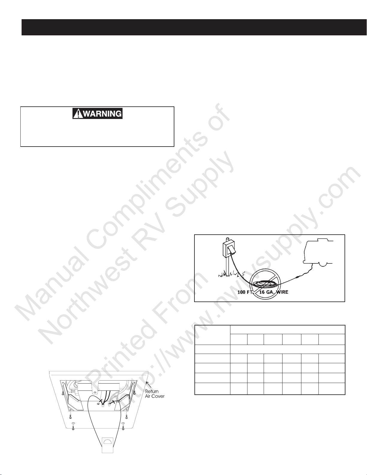
A3. Field Wiring
If the unit’s compressor or fan fails to operate, chances are
it is not receiving proper power. Be sure the power cord is
plugged in and fuses ore breakers are ope.
Note: Many customers use extremely long power cords
that are undersized. If possible, ask the owner to hook up
the RV just like it was when the problem occurred. See
FIG. A2
FIG. A2
A2. DC Volts
On certain models of electronic controlled air conditioners
and heat pumps, DC volts must be supplied to the control
board. The operational range is 10 to 16 VDC. If the DC
voltage is below 10 VDC, you could experience improper
operation of the components within the main board.
A2a. Analog Control System
A DC voltage supply is wired to the control board. The
operating range is 10-16 Volts DC, with a maximum current draw of 0.250 Amps.
To check DC volts, first check the voltage between the red
(+12) positive and black (-12) negative, at the connections
on the Analog Control Box on the roof top unit.
FIG. A1
Make note of the wire size and compare it to the chart for
wire sizing. See Section A1a - AC Control Voltage.
CURRENT WIRE SIZE
IN
AMPS 16 14 12 10 8 6
5 47 76 121 192 216 486
10 38 60 96 153 243
15 25 40 64 102 162
20 30 48 76 121
LENGTH IN FEET
1
Section A - Installation, cont’d.
Manual Compliments of
Northwest RV Supply
Printed From
http://www.nwrvsupply.com
A6a. Roof Top Units
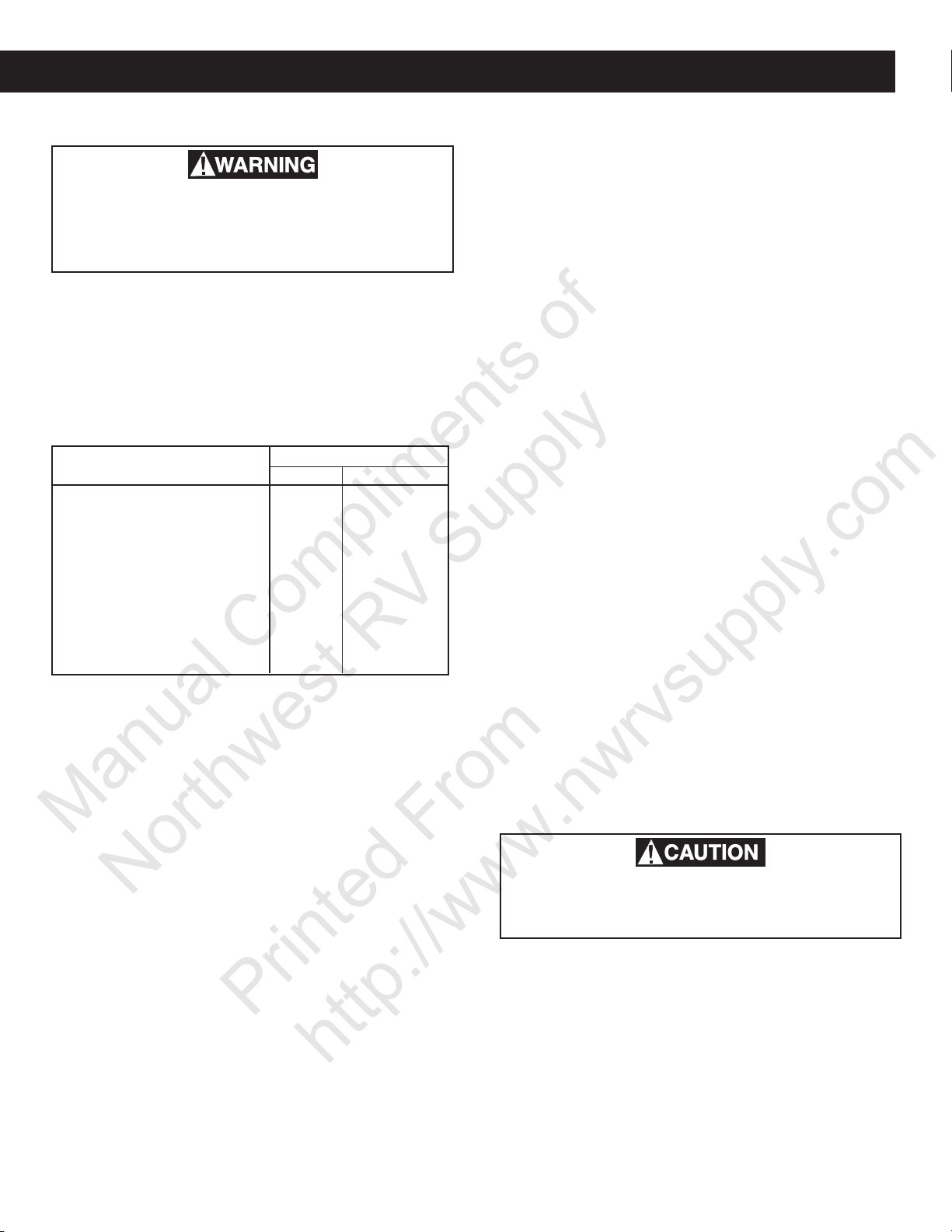
A4. Breaker
A6. Ducting
A6a. Rooftop Units
Make sure that the power supply to the unit
is disconnected before performing any work
on the unit to avoid the possibility of shock
injury or damage to the equipment.
The unit is to be protected by a time delay fuse or HACR
(heating, air conditioner, refrigerator) breaker. By taking
an amp reading at the unit AC voltage supply line, you can
determine if the breaker is tripping prematurely. Place a
clamp-on type ammeter around the black wire between the
unit and breaker. Turn ON the unit and record the amp
draw. If the breaker trips before the rated amperage, replace the breaker.
MODELS CIRCUIT PROTECTION
T.D. Fuse HACR Breaker
39125 (Basement) 15 amp 15 amp
39325 (Basement) 20 amp 20 amp
39224 (Basement)- Circuit 1 15 amp 15 amp
- Circuit 2 15 amp 15 amp
39424 (Basement)- Circuit 1 15 amp 15 amp
- Circuit 2 15 amp 15 amp
All Rooftop Units 20 amp 20 amp
59528.601 15 amp 15 amp
59529.601 15 amp 15 amp
59530.601 15 amp 15 amp
A5. Air Box
Improperly installed, the air box can be a source of cooling
problems. The air box must be sealed to the ceiling template to prevent the mixing of discharge and return air. This
will cause short cycling or frost formation on the inside coil
On heat pumps, recirculation can cause the high side pressure to build, tripping the overload and/or breaker. In some
instances, the ceiling template is bent when the anchor bolts
are overtightened, causing gaps between the air box and
the ceiling template. These gaps can be sealed with aluminum tape or a closed cell foam weather strip. The duct
connecting the air conditioner or heat pump must be air
tight. Use aluminum tape to seal the joints. The thermostat sensing bulb must be properly located to control temperature. If the sensing bulb is left curled against the side
of the electric box or used as a ground connection, improper operation will occur. Relocate the sensing bulb in
its proper place as indicated in the Installation and Operating Instructions. Check the air filters and clean.
Sizing and Design
The installer of this air conditioner system must design the
air distribution system for his particular application. Several requirements for this system MUST be met for the air
conditioner to operate properly. These requirements are
as follows:
Roof cavity thickness must be between 2.00" and 5.50".
This distance is measured between roof and ceiling surface.
The total cross-sectional discharge area of the outlet ducts
from the plenum area under the air conditioner must be as
follows:
1. 579 & 600 Series 17.5 sq. in.
2. 591, 595 & 630 Series 21.0 sq. in.
Duct Sizing Requirements as Follows:
Duct Depth (591/595/630 Series) 1-1/2" 2-1/4"
(579/600 Series) 1-1/4" 2-1/4"
Duct Width 7" — —
Total Duct Length 12 ft. 36 ft.
Duct Length (short run) 1/3 Total Length
Register Requirements as follows:
Distance from Duct End 5" 8"
Distance from End of Elbow 15" — —
Distance between Registers 24" — —
Total Number Required/AC 4 8
Number Required per Run/AC 2 — —
Free Area per Register 14 sq. in.— —
The duct material must meet or exceed any agency or RVIA
Standard that may be in existence at the time the RV is
produced.
It is the responsibility of the installer of this
system to ensure the ductwork will not collapse or bend during or after the installation.
All discharge air ducts must be properly insulated to prevent condensation from forming on their surfaces or adjacent surfaces during operation of the air conditioner or heat
pump. This insulation must be R-7 minimum.
Note: The Dometic Corporation will not be held liable for
roof, structural or ceiling damage due to improperly insulated or sealed ductwork.
Return air opening must have 40 sq. in. minimum free area
including the filter.
Min. Max.
Min. Max.
Return air to the air conditioner must be filtered to prevent
dirt accumulation on air conditioner cooling surface.
2
A6a. Roof Top Units
Manual Compliments of
Northwest RV Supply
Printed From
http://www.nwrvsupply.com
Section A - Installation, cont’d.
Total System Pressure must be between the following:
0.55 to 0.90 in. W.C. for 579 Series
0.40 to 1.10 in. W.C. for 591, 595 & 630 Series
0.12 to 0.65 in. W. C. for 600 Series
This is determined with the air conditioner blower operation on high speed and return air filter and grille in place.
The Dometic Corporation recommends the basic configuration shown below for installing this Air Conditioner System. We have found by testing that this configuration works
best in most applications of the Air Conditioner/Heat Pump
System.
It is the responsibility of the installer of this system to review each RV floor plan and determine the following:
A. Duct Size
B. Duct Layout
C. Register Size
D. Register Locations
E. Thermostat Location
These items must be determined in conjunction with the
Air Distribution System Sizing and Design Requirements
listed.
Note: Alternate configurations and methods may be used
which still allow the air conditioner to operate properly.
However, these alternate configurations and methods must
be approved by The Dometic Corporation in writing.
The following instructions are based upon the use of
Dometic Return Air Kit. The electronic control kit has
mounting bolts supplied for use with this Kit. See FIG. A3.
Before preparing the ceiling opening, the type of system
options must be decided upon. If a remote sensor is to be
used, provisions must be made for it. If the load shed option (Energy Management System feature) is to be used,
wires must be run from the load shed control to the Dometic
A/C. If a furnace is to be connected, wires must be run
from the furnace to the Air Conditioner.
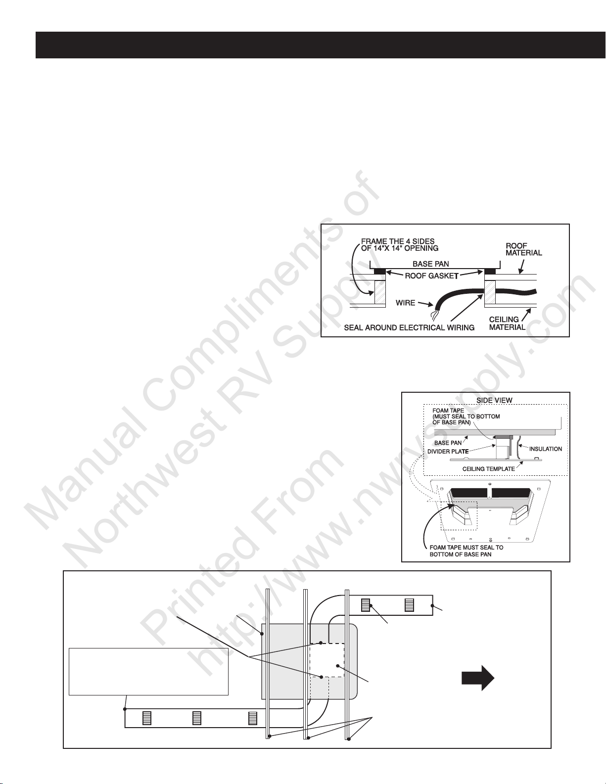
The 14-1/4" x 14-1/4" (±1/8") opening must be framed to
seal off the roof cavity. Holes used to route electrical wiring should be sealed. The 14-1/4" x 14-1/4" (±1/8") open-
ing is part of the return air duct and must be finished in
accordance with NFPA Standard 501C, Standard for Recreational Vehicles, Section 2-7.
The most commonly found installation problem is the improper sealing of the 14-1/4" x 14-1/4" (±1/8") opening in
the roof cavity. The cooled discharge and warm return air
are mixed in the roof cavity and produce conditions that
are excellent for frost production.
Even the best framing job will not stop frost from occurring
if the cold air discharge is allowed to enter into the return
air portion of the 14-1/4" x 14-1/4" (±1/8") opening. See
FIG. A4.
FIG. A4
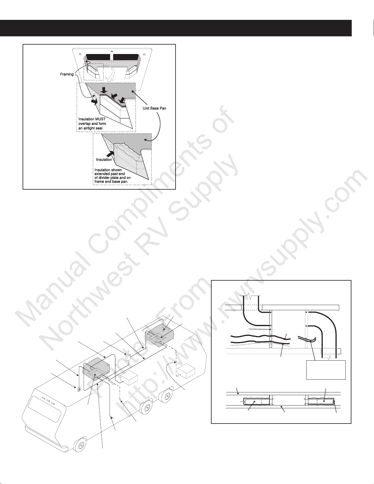
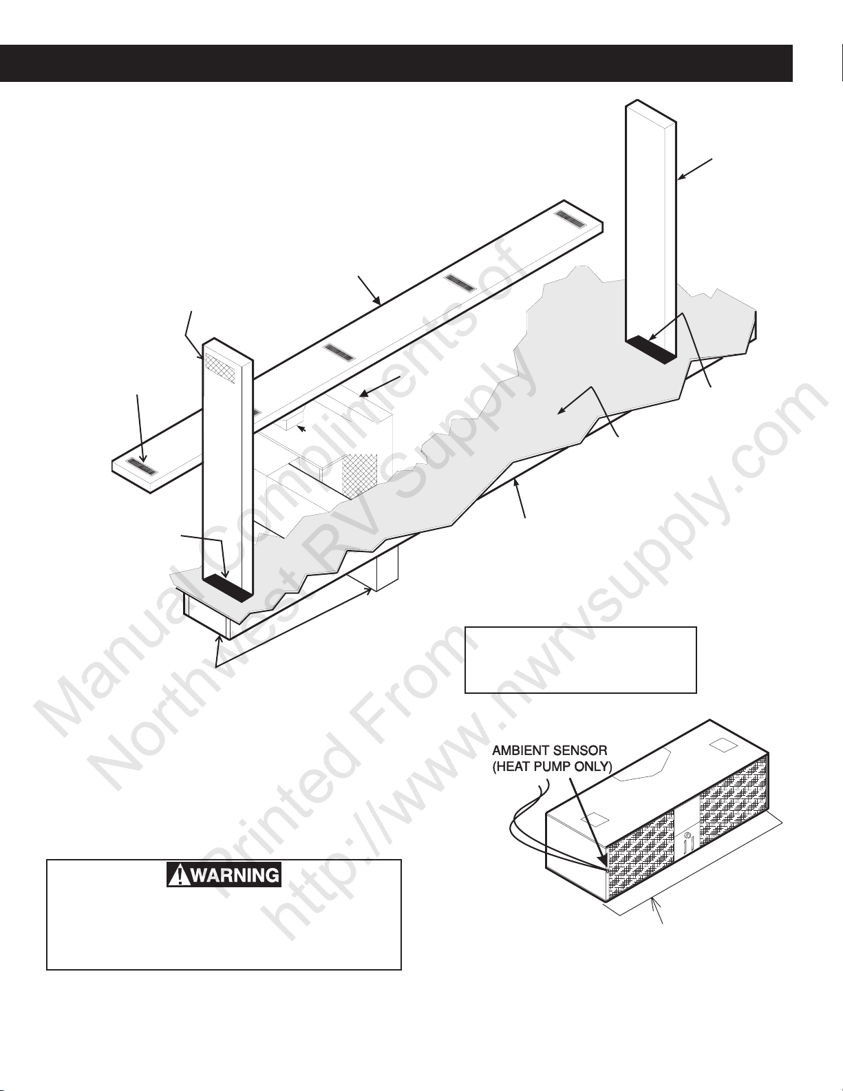
Duo-Therm’s return air kits are designed to be installed
tightly to the bottom of the base pan and ceiling template.
Insulation supplied in the kit not only stops condensation
from forming on the divider plate, but prohibits air leaks as
well. The insulation
is purposely oversized to be attached to the sides
of the 14-1/4" x 141/4" (±1/8") opening and the base of
the air conditioner
and ceiling template. Make sure
the data plate does
not get covered
with insulation.
See FIG. A5.
FIG. A5
FIG. A3
TOTAL OUTLET
AIR AREA MINIMUM:
17.5 sq. in. - 579 & 600 Series
21.0 sq. in. - 590 & 595 Series
DUCTS MIN. MAX.
DEPTH (590 & 595 Series) 1-1/2" 2-1/4"
(579 & 600 Series) 1-1/4" 2-1/4"
WIDTH 7" — —
TOTAL LENGTH 12' 36'
AIR CONDITIONER
If a Remote Temperature Sensor is to be used, (Comfort
REGISTERS
4 MIN. — 8 MAX. (Per A/C)
14 SQ. IN. FREE AREA
PER REGISTER
14 INCH ROOF
OPENING
ROOF RAFTERS
3
THE MINIMUM SHORT DUCT
RUN MUST EQUAL 1/3 OF
TOTAL DUCT LENGTH
VEHICLE
FRONT
REAR REMOTE SENSOR
(Required with Second
Air Conditioner)
14-1/4" x 14-1/4"
(±1/8”) OPENING
14-1/4" x 14-1/4"
(±1/8”) OPENING
OPTIONAL
FURNACE
FURNACE
2 WIRES
OPTIONAL FRONT
REMOTE SENSOR
12V DC INPUT
2 WIRES
4-CONDUCTOR
CONTROL CABLE
BREAKER BOX
115V AC
REAR A/C
4-CONDUCTOR
CONTROL CABLE
115V AC
FRONT A/C
FURNACE
2 WIRES
DOMETIC COMFORT
CONTROL CENTER
Section A - Installation, cont’d.
FRAME
14-1/4" (±1/8”)
OPENING
AC POWER
SUPPLY WIRE
DUCT
FRAME
FRAME
CCC, CONTROL CABLE(S)
or 7-Wire Analog Cable
LOW VOLTAGE WIRES:
12VDC
Furnace
Load Shed
Sensors
DUCT
ROOF
INSULATION
DUCT TO REAR
CEILING
DUCT TO FRONT
14-1/4" (±1/8”)
OPENING
INSULATION
SIDE VIEW
(TOWARD BACK OF RV)
TOP VIEW
(BACK OF RV)
Manual Compliments of
Northwest RV Supply
Printed From
http://www.nwrvsupply.com
A6a. Roof Top Units
Control Center configuration, page 16) the connector end
must be routed to the roof opening of the system which it
will control. Make sure that at least 15" of the sensor cable
extends into the roof opening. If a furnace is to be controlled by the system, the two furnace thermostat leads must
be routed to the roof opening of the air conditioner that will
control it. Make sure at least 15" of the furnace thermostat
wires extend into the roof opening. If an Energy Management System - EMS (load shed) is to be used with the
control, two wires must be routed to the roof opening of the
zone to be managed. The signal required for this function
is a normally open relay contact. When the EMS calls for
the compressor to shut off, the relay contacts should close.
Make sure that at least 15" of the EMS wires extend into
the roof opening.
DOMETIC COMFORT
CONTROL CENTER
FIG. A6
Route a copper 12 AWG, with ground, 115 VAC supply line
from the fuse or circuit breaker box to the roof opening.
a. This supply line must be located in the front portion of
the 14-1/4" (±1/8") opening.
b. The power supply MUST be on a separate Time Delay
Fuse or HACR Circuit Breaker.
c. Make sure at least 15" of supply wire extends into the
roof opening. This ensures easy connection at the
Junction Box.
d. Wiring must comply with all National, State and Local
Wiring Codes.
e. Use a steel sleeve and a grommet or equivalent meth-
ods to protect the wire where it passes into the open-
ing.
Route a dedicated 12 VDC supply line (18-22 AWG) from
the RV’s Converter or Battery to the roof opening.
a. This supply line must be located in the front portion of
the 14-1/4" (±1/8") opening.
b. Make sure that at least 15" of supply wire extends into
the roof opening.
c. In a multiple zone installation, this wiring is required in
only one of the 14-1/4" (±1/8") openings.
Route a 4-conductor telephone cable from the Comfort
Control Center™ mounting position into the 14-1/4" (±1/
8") roof opening. Make sure that at least 15" of the wire
extends into the roof opening and 6" extend from the wall
at the mounting position of the Comfort Control Center™.
In the event that other A/C’s are to be installed (additional
zones) and additional 4-conductor telephone cable must
be routed to the other A/C’s. Make sure that at least 15" of
the wire extends into each of the roof openings. See FIG.
A8.
FIG. A8
REAR REMOTE SENSOR
115V AC
FIG. A7
4-CONDUCTOR
CONTROL CABLE
FURNACE
2 WIRES
4-CONDUCTOR
CONTROL CABLE
BREAKER BOX
14-1/4" x 14-1/4"
(±1/8”) OPENING
115V AC
FRONT A/C
REAR A/C
FURNACE
OPTIONAL FRONT
12V DC INPUT
2 WIRES
REMOTE SENSOR
(Required with Second
Air Conditioner)
14-1/4" x 14-1/4"
(±1/8”) OPENING
OPTIONAL
FURNACE
FURNACE
2 WIRES
A seven-conductor cable, 18-22 AWG is to be used for low
voltage connections for Analog Controls. Choose the shortest, direct route from the 14" opening to the thermostat
location selected. Consider where screws, nails or staples
might contact the cable. See FIG. A8.
4
A6a. Roof Top Units
Manual Compliments of
Northwest RV Supply
Printed From
http://www.nwrvsupply.com
Leave approximately 6" of cable extending through the wall
for connection to thermostat. Leave approximately 10" of
cable extending into the 14-1/4" (±1/8") opening for connection at Relay Kit. See A7 Thermostat Location, page
12.
If System if to control a gas furnace:
Route two 18 AWG from the furnace to 14-1/4" (±1/8") opening at this time.
FIG. A9
Section A - Installation, cont’d.
FIG. A10
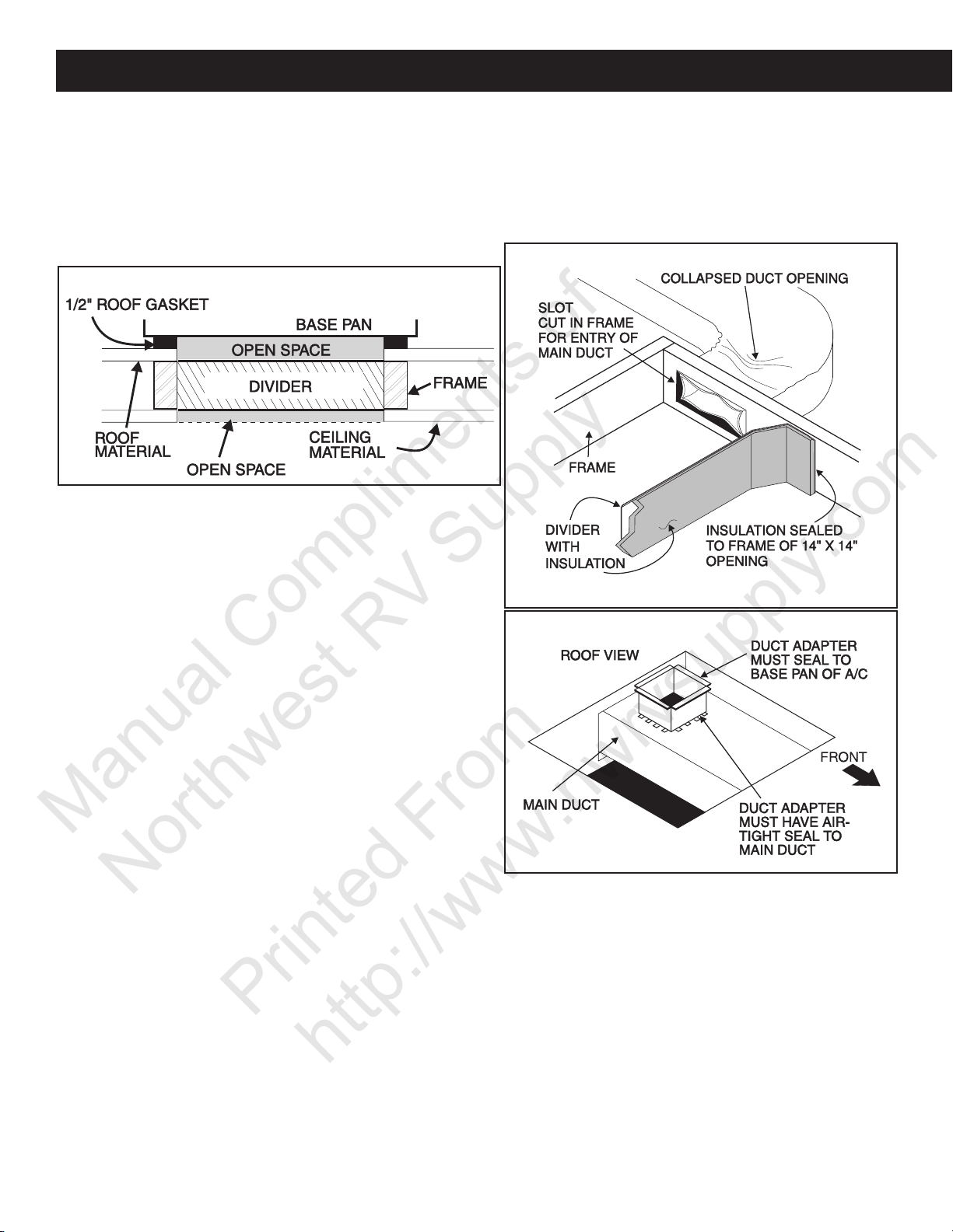
In some installations, the OEM supplies their own return
air kits. Sometimes both the return and the discharge air
are ducted to and from the 14-1/4" x 14-1/4" (±1/8") opening. In some cases the bottom of the 14-1/4" x 14-1/4" (±1/
8") opening is covered with ceiling material.
In this type of installation the 14-1/4" x 14-1/4" (±1/8") opening is divided. If the divider only fills to the thickness of the
ceiling cavity, an air gap may be created both on the top
and bottom of the thickness of the roof gasket, roof or ceiling material. A gasket, etc., must be used to fill up the
open space to reduce recirculation. See FIG. A9.
Another method of connecting the discharge air to the
coach’s main duct used Duo-Therm’s return air kit. It uses
half of the 14-1/4" x 14-1/4" (±1/8") opening as a discharge
plenum. If the duct opening is not clean, restriction of air
can cause the coil to freeze. The opening of the duct should
be as large as possible to make the air distribution better in
the coach and reduce freeze-up. See FIG. A10.
The final method of installation dumps the discharge air
directly into the RV’s main duct. The duct is routed through
the 14-1/4" x 14-1/4" (±1/8") opening. A duct adapter is used
to connect the air conditioner to the main duct. If this connection is not made properly, cold air can migrate back into
the return air path and make conditions right for freeze-up.
Be sure the duct adapter is sealed to the main duct and air
conditioner. See FIG. A11.
FIG. A11
5

Section A - Installation, cont’d.
Manual Compliments of
Northwest RV Supply
Printed From
http://www.nwrvsupply.com
A6a. Roof Top Units
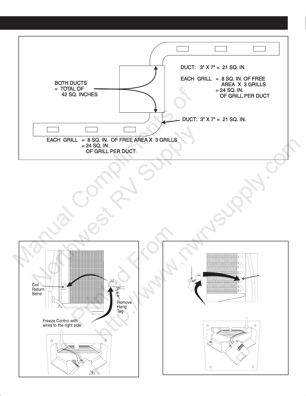
Restrictions at the connection to the air conditioner is the
most common cause, but blockage in the main duct runs
can also cause freeze-up. Blockages commonly occur in
the areas where the duct changes direction. Other obstacles that can cause a change in the duct (air) path include rafters, vent pipes, wire bundles, etc. See FIG. A12.
A good way to check for duct blockage is with a flashlight
and a mirror. Remove ceiling register cover to allow a flashlight to be put in the duct and use a mirror to view the flashlight from the next register opening. A blockage will be
visible in the mirror. See FIG. A12.
Duo-Therm has available a quick cool return air kit that will
allow the cooled air to come directly out of the air conditioner. This will bypass any restrictions in the coach duct
system. (Part No. 3105958.007 Shell White, 3105958.015
Polar White).
If the main duct in the vehicle is undersized, the volume of
air flowing through the ducts will decrease. The coil temperature will also drop because not enough air is moving
through it. The requirements for proper duct size are shown
in FIG. A13.
Up to this point we have mainly covered the discharge side;
however, restrictions of the return air can result in frost
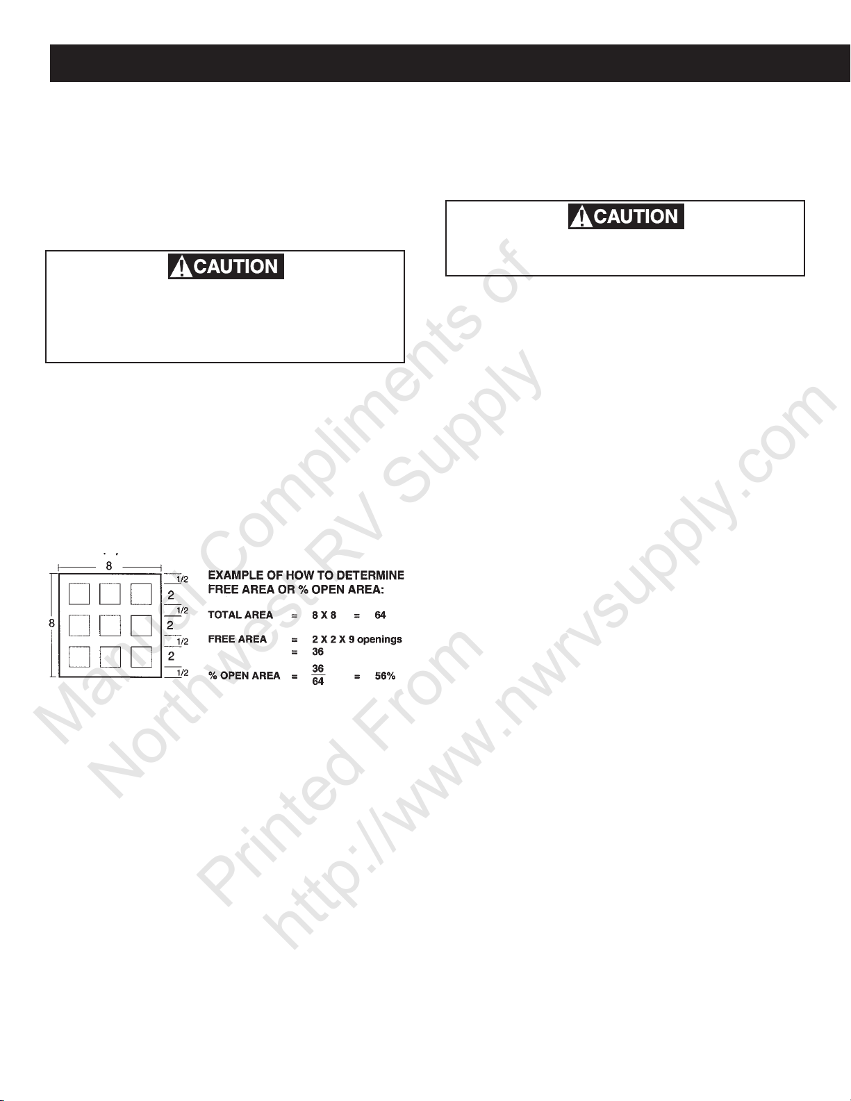
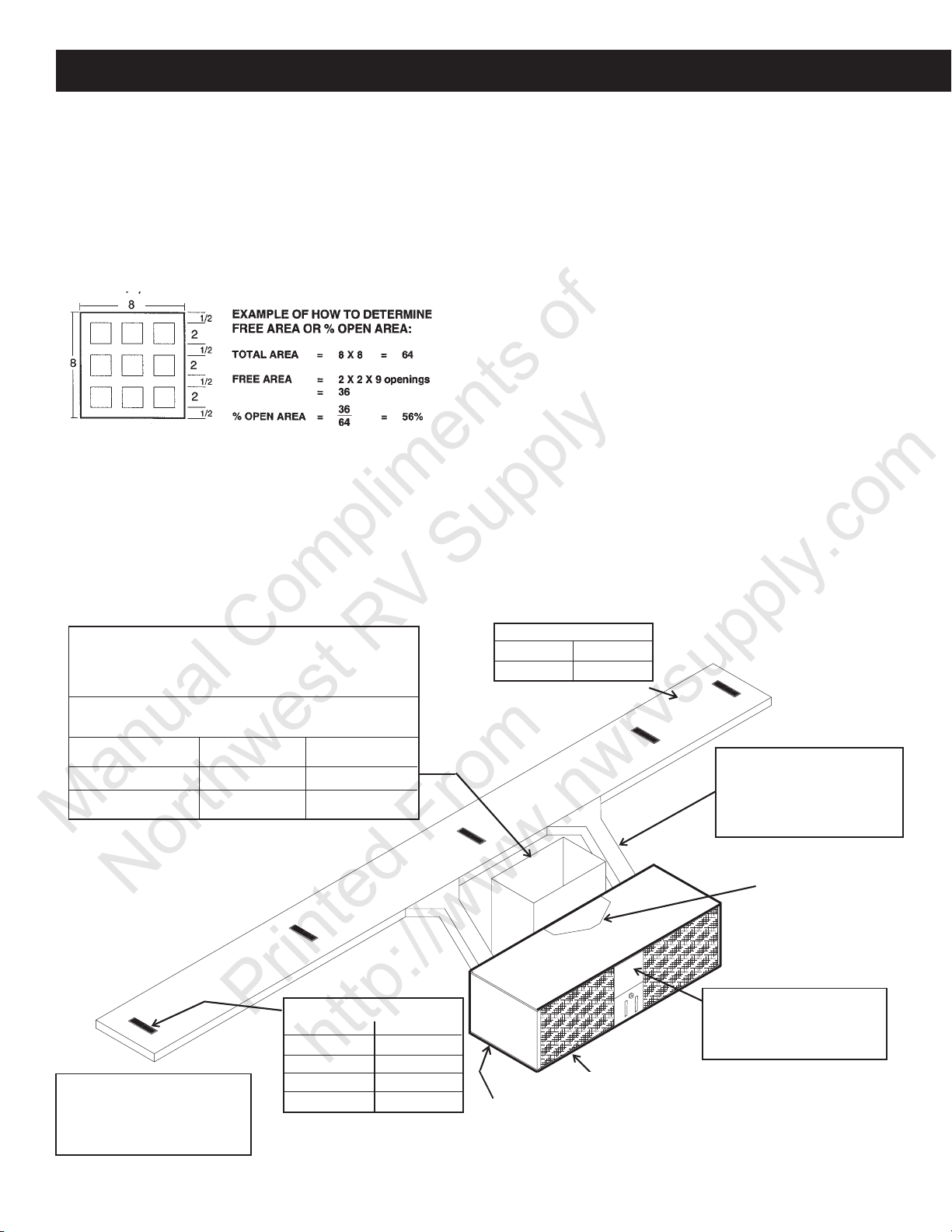
buildup. The Duo-Therm air conditioner requires a minimum of 40 square inches of FREE AREA.
FREE AREA - is the opening that remains in a grill or louvered panel after the restrictions are taken away. For example, an opening of 10 x 20 inches has 200 square inches.
When this opening is covered with a grill that is 56 percent
open, the FREE AREA is (200 x .56), 112 square inches.
Dometic return air kits are designed to have the correct
free area; however some manufacturers use their own grills.
If a manufacturer’s grill is used, it must use the above formula to make sure the return air is sufficient to reduce the
chances for freeze-up. The filter material must also be considered as a restriction and subtracted from the FREE
AREA. See FIG. A14.
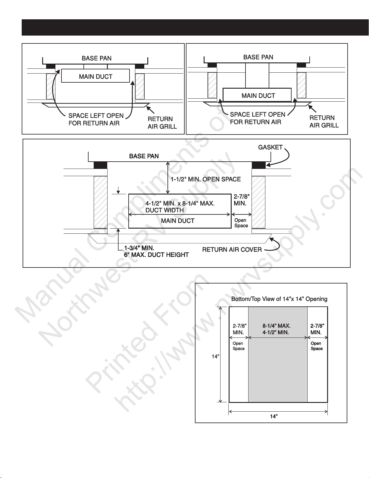
Main ducts running through the 14-1/4" x 14-1/4" (±1/8")
opening must leave space between the duct and return air
grill or duct and bottom of the air conditioner. See FIG.
A15, A16, A18.
FIG. A12
FIG. A13
TOTAL OUTLET
AIR AREA MINIMUM:
17.5 sq. in. - 579 & 600 Series
21.0 sq. in. - 590 & 595 Series
AIR CONDITIONER
"S" PATTERN DUCT SYSTEM
DUCTS MIN. MAX.
DEPTH (590 & 595 Series) 1-1/2" 2-1/4"
(579 & 600 Series) 1-1/4" 2-1/4"
WIDTH 7" — —
TOTAL LENGTH 12' 36'
FIG. A14
REGISTERS
4 MIN. — 8 MAX. (Per A/C)
14 SQ. IN. FREE AREA
PER REGISTER
14 INCH ROOF
OPENING
THE MINIMUM SHORT DUCT
RUN MUST EQUAL 1/3 OF
TOTAL DUCT LENGTH
ROOF RAFTERS
6
A6a. Roof Top Units
Manual Compliments of
Northwest RV Supply
Printed From
http://www.nwrvsupply.com
Section A - Installation, cont’d.
FIG. A15
FIG. A17
FIG. A16
The gap between the top and the main duct to the bottom
of the air conditioner should be a minimum of 1-1/2". See
FIG. A17 & A18.
If the return air is ducted into the 14-1/4" X 14-1/4" (±1/8")
opening, the duct must be equal to the 40 sq. inches that
are needed by the air conditioner. Grill or registers used
ing this duct must be equal to or greater than the duct in
square inches.
The control system used by Duo-Therm Air Conditioner is
designed with a low temperature switch that will shut off
the compressor and allow air to flow through the coil to
melt the frost. A properly operating cold control may allow
a slight coating of frost to form on the evaporator coil before it turns off the compressor. If the cold control is not
installed in its intended mounting locations, frost buildup
can block all air flow through the evaporator coil and stop
cooling inside the RV. The cold control has clips that allow
it to be snapped onto the turn/bends of the evaporator coil.
See FIG. A20 & A21 for the correct location.
FIG. A18
7
Section A - Installation, cont’d.
Freeze Control with wires.
Coil
Return
Bend
Do
kdkd
mfmf
Remove
Hang
Tag
Manual Compliments of
Northwest RV Supply
Printed From
http://www.nwrvsupply.com
FIG. A19
A6a. Roof Top Units
Freeze Control Installation
579, 590 & 595 Series:
a. Snap freeze control into place on return bend located
at left side of evaporator coil as follows:
1) Locate “D” shaped notch in flange of evaporator
coil.
2) Place the horseshoe end of freeze control through
this notch and snap onto coil return bend. When
positioned correctly, control wires will be 90° to direction of coil fin surface. See FIG. A20
Note: Freeze control is not used on heat pump coils. Some
will have the “D” slot in the coil header.
579, 590 & 595 SERIES
FIG. A20
Mount the Freeze Control on left side
of coil, with wires to the right side
Freeze Control Installation
600 Series:
a. Snap the freeze control into place on return end lo-
cated at right side of evaporator coil as follows:
1) Locate vertical return bend at lower right of evaporator coil.
2) Place the horseshoe end of freeze control onto this
coil return bend and snap into place. When positioned correctly, control wires will be 90° to direction of coil fin surface. See FIG. A21.
Note: Freeze control is not used on heat pump coils, some
FIG. A21
600 SERIES
Install Freeze Control with wires as shown
8
A6b. Basement Units
Manual Compliments of
Northwest RV Supply
Printed From
http://www.nwrvsupply.com
Section A - Installation, cont’d.
will have the “D” slot in the coil header.
A6b. Basement Units
Models 39335 and 39125
Outdoor Section:
The Condenser coil is designed to have a fresh supply of
air. If skirting is installed, allow a louvered grill with 330
square inches for supply air and a louvered grill on opposite side of coach (330 square inches) for discharge air.
Do not totally enclose the underside of the
unit. Air circulation prevents heat from building under unit and your system will perform
as designed.
The condenser section is a “blow-through” type. When the
face of the coil is positioned behind a louvered or other
type of restrictive opening, the FREE AREA of the opening
must be at least 260 square inches.
FREE AREA - is the opening that remains in a grill or louvered panel after the restrictions are taken away. For example, an opening of 10 x 20 inches has 200 square inches.
When this opening is covered with a grill that is 56 percent
open, the FREE AREA is (200 x .56), 112 square inches.
Expanded and perforated metal grills in general vary from
Indoor Section:
Clearances
The minimum clearances to the evaporator are zero inches
to the bottom, top, left and right sides. Access to the electrical connections and drain connection must be provided
when making the installation.
Be sure to allow sufficient room to service
the electrical components.
Inlet Air
The evaporator section must have free access to room air.
A minimum or 180 square inches of FREE AREA opening is required. Where the return air must be provided
through louvers or mesh scree, the FREE AREA percentage of the material used shall be taken into consideration
when making this determination. An example of how to
determine FREE AREA is included under “Outdoor Sec-
tion”.
Grills and Registers
Note: The return air grill must have the same square sur-
face as the coil face (15"H x 17"L).
For each air conditioning system, there must be a return
grill to bring cabin air back into the unit. There must also
be at least four discharge grills per unit.
Each return air grill must be filtered and accessible for cleaning and replacement.
Outlet Air
The central air conditioning unit is designed to use a discharge air duct with a static pressure of .10 to .25 inches
water column. Proper duct size is necessary to maintain
proper air flow without loss of static pressure and provide
30 percent to 60 percent open. Be certain that 260 square
inches of FREE AREA is available to the face of the condenser.
Note: Service access must always be supplied either as
clearance or as a defined access panel.
Mounting
Vibration eliminators are supplied to prevent the transmittance of vibration into the living area.
The air conditioning unit may be attached to rails beneath
the vehicle, attached to the frame, or mounted directly to
the floor of some vehicles.
Unit should be mounted with a tilt toward the rear (condenser) a half-bubble using a level. Unit rear should be 1/
4" lower than the front.
Service Access
Be sure NOT to block the inlet or discharge air, or service
access, when mounting.
good air circulation.
All air handling ducts must be properly insulated to prevent
condensation forming on their surface during operating. A
vapor barrier must also be supplied on the outer surface of
the insulation to prevent moisture from traveling through
the insulation and condensing on the cold ductwork.
Note: If the air conditioning unit is attached to the central
furnace, a damper must be installed at the furnace outlet
to prevent cold air from circulating through the furnace heat
exchanger, unless furnace is so equipped to utilize the builtin furnace relay.
9
Section A - Installation, cont’d.
Manual Compliments of
Northwest RV Supply
Printed From
http://www.nwrvsupply.com
FIG. A22
2" X 12" INSULATED
90 SQ. IN.
FILTERED
(MIN. X 2)
DUCT (MIN.)
A6b. Basement Units
RETURN
RISER X 2
2" X 10" CLOSEABLE
GRILL (MIN. X 4))
SUPPLY AIR
INSULATED
FLOOR CUTOUT
90 SQ. IN. MINIMUM
MIN. 180 SQ. IN.
REQUIRED OPENING
Models 39224 and 39424
Condenser Section:
Supply Air
The inlet of the condenser coil should be positioned so that
it draws air from outside the vehicle. Special care must
be taken to prevent the discharge air from recirculating to the inlet of the condenser coil. Shields should be
added to ensure fresh air supply.
DISCHARGE
CONDENSER
AIR
ENCLOSED
FLOOR JOIST
RETURN SYSTEM
-Risers use interior wall structure
-Using floor joists area for return to unit
-Each return grill is filtered
FIG. A23
FLOORING
FLOOR CUTOUT
90 SQ. IN. MINIMUM
Do not install the condenser where the fan
will draw air from the exhaust of the vehicle,
a motor generator set, transmission, road
heat or ANY other heat producing source.
FIELD INSTALLED SHIELD THAT WILL PREVENT
RECIRCULATION OF CONDENSER AIR.
The condenser section is a “draw-through” type. When the
face of the coil is positioned behind a louvered or other
type of restrictive opening, the FREE AREA of the opening
must be at least 460 square inches.
10
A6b. Basement Units
Manual Compliments of
Northwest RV Supply
Printed From
http://www.nwrvsupply.com
Section A - Installation, cont’d.
FREE AREA - is the opening that remains in a grill or lou-
vered panel after the restrictions are taken away. For example, an opening of 10 x 20 inches has 200 square inches.
When this opening is covered with a grill that is 56 percent
open, the FREE AREA is (200 x .56), 112 square inches.
Expanded and perforated metal grills in general vary from
30 percent to 60 percent open. Be certain that 460 square
inches of FREE AREA is available to the face of the condenser.
Note: Service access must always be supplied either as
clearance or as a defined access panel.
Clearances
The air conditioning unit clearances depend on:
1. Inlet air access used
2. Discharge air duct arrangement
3. Return air duct
4. Storage compartment location and design
A one (1) inch clearance is required on three (3) sides of
the air conditioner if the top return is used. When using the
side access for return, please allow a minimum of eight (8)
inches for the return air duct. Access to the electrical connections must be provided when making the installation.
Evaporation Section:
Inlet Air
The evaporation section must have free access to room
air. A minimum of 128 square inches of FREE AREA opening is required. Where the return air must be provided
through louvers or mesh screen, the FREE AREA percentage of the material used shall be taken into consideration
when making this determination. An example of how to
determine FREE AREA is included under Condenser Sec-
tion. See FIG. A24.
FIG. A24
RETURN SYSTEM
Return to be 6 ft. minimum from floor.
Use wall structure for delivery to basement area.
Return grille must be filtered.
Minimum return required per duct sizing for unit to
perform within Engineering specifications. See Chart below:
DUCT SIZE MINIMUM MAX.
40 IN.
60 IN.
2
2
128 IN.
128 IN.
2
2
189 IN.
189 IN.
2
2
INSULATED DUCT
Minimum Maximum
2
40 IN.
(3 " depth Min.)
60 IN.
REGISTER REQUIREMENTS
ADDITIONAL REQUIREMENTS:
Damper required in furnace.
Vibration isolators should be
used at each mounting point.
12 VDC required for Comfort
Control operation.
REQ. SIZE MIN. QTY.
4 X 6 4
4 X 8 4
4 X 10 4
4 X 12 4
Condenser air outlet ( X2 in bottom)
Must be isolated from condenser inlet air.
Condenser inlet air 2 places.
2
Supply Duct must be insulated.
Supply Duct from air conditioner
must be equal to or greater
in IN.2 as the floor ductwork.
Use 45 degree angle on inlets
& outlets
Optional return area.
May be used in
conjunction with side
return.
Electrical box access required.
Each circuit, 15 AMP HACR
breaker
11
Section A - Installation, cont’d.
Manual Compliments of
Northwest RV Supply
Printed From
http://www.nwrvsupply.com
Grills
Note: The Return air grill must have the same square sur-
face as the return air duct.
1. For each air conditioning system, there must be a return grill to bring cabin air back into the unit. There
must also be at least four discharge grills per unit.
2. Return grills must be mounted in front of the evaporator. If this is not possible, make sure there is nothing
blocking the air flow from the grill to the evaporator.
3. The unit must have a return filter between the grill and
the unit. This filter must be accessible for periodic cleaning.
Outlet Air
The air diffusion system, supplied by the installer, must be
sized to maintain a static pressure at the blower outlet between .4 and 1.2 inches water column.
All air handling ducts must be properly insulated to prevent
condensation forming on their surface during operation. A
vapor barrier must also be supplied on the outer surface of
the insulation to prevent moisture from traveling through
the insulation and condensing on the cold ductwork. See
section A6a - Rooftop Units.
A7. Thermostat Location
The thermostat location is very important for balanced
temperature control in any RV.
Today’s interior design has become both cosmetically more
appealing and more efficient in its use of storage space.
These improvements have generated complex interior
space requirements which, in turn, have caused many RV’s
to become a maze for heating and air conditioning circulation.
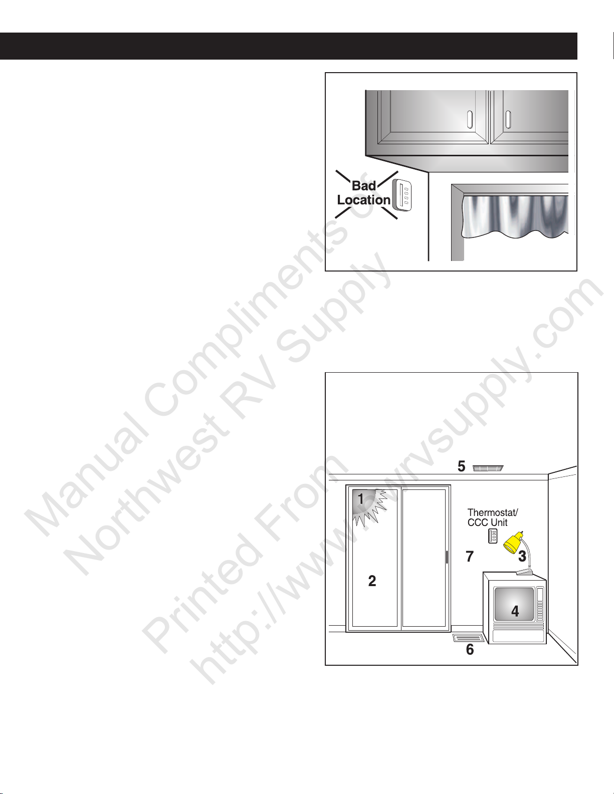
FIG. A25
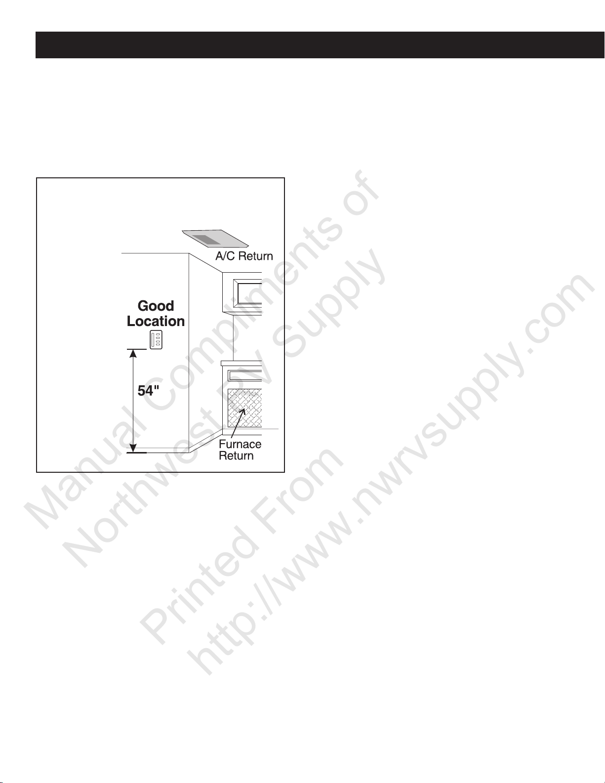
The proper location for the thermostat or remote sensor is
54" from the floor and on an inside wall. It should be located where it cannot be affected by heat from the sun,
lamps, oven, etc., or other sources of draft. Locations close
to entry doors and windows should be avoided. The discharge from registers blowing directly on the thermostat or
remote sensor can cause the system to short-cycle and
should be avoided. See FIG. A26.
FIG. A26
Examples of Bad Thermostat Locations
1, 3, 4 Near Heat Sources
2 Near Drafts or Heat source
5, 6 Near Drafts
7 On an Outside Wall
The heating system is usually mounted close to floor level
and consists of one or more furnaces. The air conditioner(s)
is mounted on the roof with a different air distribution system. It is very important to locate the thermostat and remote sensors in areas that have good air movement. This
may be difficult because what works well for heating may
not work well for air conditioning.
The thermostat or remote sensors must be placed in a location with good air movement. Placing a thermostat or
sensor under a cabinet or in a corner will result in a large
fluctuation in the temperature. See FIG. A25.
12
When the floor plan or interior design of an RV changes,
Manual Compliments of
Northwest RV Supply
Printed From
http://www.nwrvsupply.com
Dometic suggests trying several locations for the thermostat or remote sensor to determine the best location for
mounting. Both heating and air conditioning should be
tested, especially when using different duct systems and
the same thermostat. When the proper thermostat or remote sensor location is determined, this location can be
used on other RV’s with the same basic plan. See FIG.
A27.
FIG. A27
Example of
Good Thermostat Location
(Interior Hallway Wall)
Section A - Installation, cont’d.
13
Section B - Operation
Manual Compliments of
Northwest RV Supply
Printed From
http://www.nwrvsupply.com
B. Operation
The recreational vehicle manufacturer has equipped the
vehicle with Duo-Therm’s Air Conditioner. The ability of
the unit to maintain the desired inside temperature depends
on the heat gain of the RV. Some preventative measures
can be taken by the occupants of the RV to reduce the
heat gain and improve the performance of the unit. During
extremely high outdoor temperatures, the heat gain of the
vehicle may be reduced by:
1. Parking the RV in a shaded area.
2. Using window shades (blinds and/or curtains).
3. Keeping windows and doors shut or minimizing usage.
4. Avoid use of heat producing appliances.
5. Starting the unit early in the morning and giving it a
“head start” on the expected high outdoor temperatures will greatly improve its ability to maintain the desired indoor temperature.
The operating instructions can change from one model to
another.
Be sure you are familiar with the proper operating instructions for the specific model of air conditioner you are diagnosing. An installation and operating manual is packaged
with each air conditioner system.
B1. Air Conditioners
Mechanical Cooling Operation
Set the thermostat at the desired temperature level. Select the fan speed that best satisfies your needs. See FIG.
B1.
a. HIGH COOL - Selected when maximum cooling
and dehumidification is required.
b. MED. COOL - Selected when normal or average
cooling is required.
c. LOW COOL - Selected when room is at desired
comfort level and needs to be maintained. Normally this speed is used for nighttime operation.
Note: The blower runs continuously to circulate air and
maintain an even temperature. The compressor will come
on as cooling is required to maintain the selected temperature level.
After shutting the air conditioner down with
either selector switch or thermostat, wait at
least two (2) minutes before restarting. This
allows the refrigerant pressure to equalize
and compressor to restart easily.
Fan Operation
This will circulate the air in your RV without cooling or heating. There are three positions: HIGH FAN, MED. FAN or
LOW FAN to select from, depending upon personal choice.
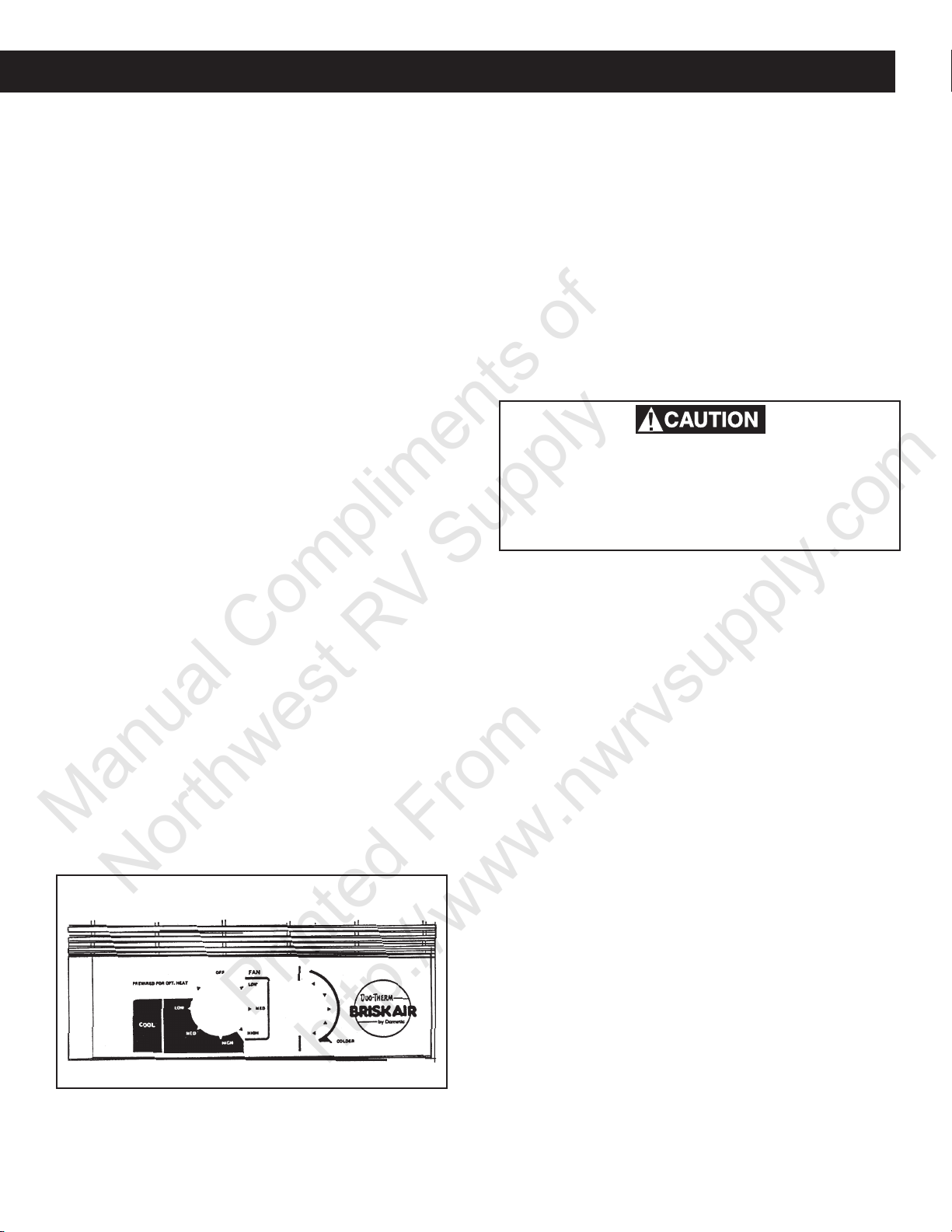
B1a. Mechanical Controls
This type of air conditioner has an air distribution box that
has a mechanical selector switch and thermostat installed
in it.
Controls
The Selector Switch has eight positions including “OFF”.
This controls fan speed, heating mode and cooling modes.
The Thermostat controls the temperature range from 65°F
on the coldest side to 90°F on the warmest side. In the
cooling mode, the compressor ON/OFF is controlled by
the thermostat setting. See FIG. B1.
Heating Operation
(With Optional Heat Kit Installed)
Note: This electric heater will not replace a furnace for
heating your RV in cold weather. The intent is to remove
the chill on cool days or mornings.
1. Turn the selector switch to “OPT. HEAT”.
2. The heater will come on and begin heating.
3. When desired temperature level in RV is reached, move
the selector switch to off position or fan position.
Note: Thermostat does not control heater ON/OFF cycle.
“OFF” Position turns unit off. See FIG. B1.
B1b. Bimetal Relay Controls
FIG. B1
This type of air conditioner has a wall mounted bimetal thermostat and a relay board that replaces the mechanical
switch and thermostat on the mechanical units and replaces
the main board and control board on the electronic units.
Note: Remember to check the installation and operating
instructions for the specific model of air conditioner you
are diagnosing.
14
B1b. Bimetal Relay Controls
Manual Compliments of
Northwest RV Supply
Printed From
http://www.nwrvsupply.com
Section B - Operation, cont’d.
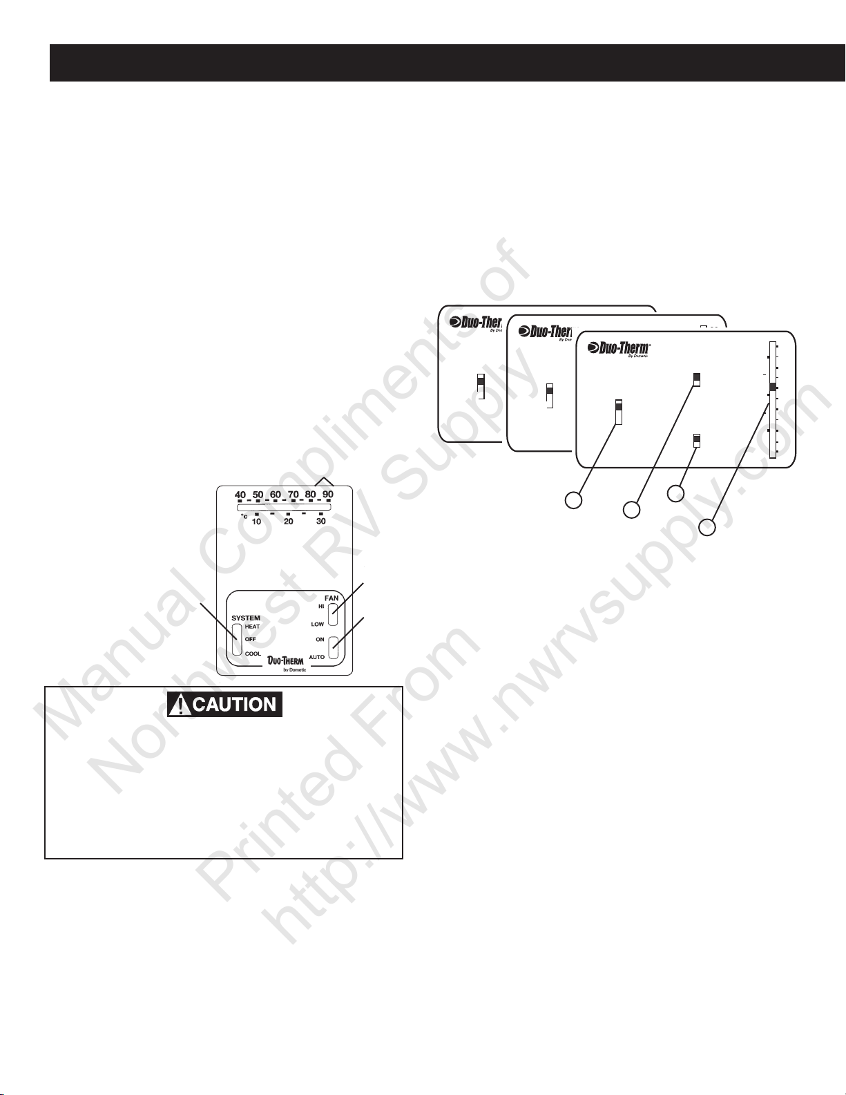
Cooling Operation
Place the Temperature Set Lever to desired temperature
level (located at top of thermostat). Select fan speed that
best satisfies your needs: (upper right switch at bottom of
thermostat). See FIG. B2.
a. High Speed: Selected when maximum cooling and
dehumidification are required.
b. Low Speed: Selected when RV reaches desired com-
fort level and needs to be maintained. Normally this
speed is used for nighttime operation.
Select Auto/ON Switch operation as follows:
(Lower right switch at bottom of thermostat)
a. Auto Position: Air conditioner fan runs whenever cool-
ing is required and stops whenever cooling is not re-
quired.
b. On Position: Air conditioner fan runs continuously to
circulate air in RV.
Set the Heat/OFF/Cool Switch to cool position
(Located at lower left side of thermostat)
The air conditioner will now come on when cooling is required and cycle off when the temperature level selected is
reached.
1
FIG. B2
1 = Temp Set Lever
2 = Auto/ON Switch
3 = System Switch
4 = Fan Speed
4
Special Feature
When thermostat:
Heat/Off/Cool Switch is in the OFF or HEAT position
and Auto/On Switch is in the ON position, the air con-
ditioner fan will run continuously to circulate the air inside the RV. See FIG. B2.
B1c. Analog Control System
In order to familiarize yourself with the operation of the
Analog Control System, the following diagrams along with
the accompanying text will explain all the functional characteristics of the system.
FAN
ON
SYSTEM
COOL
OFF
FURNACE
HEAT PUMP
SYSTEM
COOL
OFF
FURNACE
HEAT PUMP
HEAT STRIP
AUTO
HI
FURNACE
LO
HEAT PUMP
FIG. B3
3
1. Temperature Set Lever
2. Fan Auto/On Switch
3. System Switch
4. Fan High/Low Switch
ON
AUTO
SYSTEM
COOL
OFF
HI
LO
30
20
10
°C
FAN
2
90
80
70
60
50
40
4
AUTO
90
30
80
FAN
70
ON
20
60
50
10
°C
40
HI
LO
30
20
10
°C
1
90
80
70
60
50
40
3
2
Analog Control Cooling Operation
1. Place the Temperature Set Lever (1) to desired tem-
perature level. See FIG. B3.
2. Select desired fan speed by moving the Fan Speed
Switch (4) to :
a. High speed: Selected when maximum cooling and
dehumidification are required.
Wait at least two (2) minutes before restarting the air conditioner after shutting off with
either the Heat/OFF/Cooling Switch of the
Temperature Set Lever. This allows the refrigerant pressure in the air conditioner to equalize and will allow the compressor to restart
easily.
Heating Operation
(If furnace is connected to Thermostat)
Set Temperature Set Lever to desired temperature level
(located at top of thermostat). See FIG. B2.
Set the Heat/Off/Cool Switch to heat position (located at
lower left side of thermostat). See FIG. B2.
The furnace will now come on when heat is required and
cycle off when temperature level selected is reached.
b. Low speed: Selected when RV reaches desired
comfort level and needs to be maintained. Normally this speed is used for night time operation.
3. Move the FAN Auto/On Switch (2): See FIG. B3
a. Auto Position: Unit fan runs whenever cooling is
required and stops whenever cooling is not required.
b. ON Position: Unit fan runs continuously to circu-
late air in RV. See FIG. B3.
4. Set the System Switch to cool position. The unit compressor will now come ON and cycle OFF when the
temperature level selected is reached.
Furnace Operation
(If furnace is connected to relay box.)
1. Set the Temperature Set Lever (1) to desired tem-
perature setting. See FIG. B3
2. Set the System Switch (3) to furnace position. The
furnace will now come ON when heat is required and cycle
OFF when the temperature setting selected is reached.
15
Section B - Operation, cont’d.
Manual Compliments of
Northwest RV Supply
Printed From
http://www.nwrvsupply.com
B1d. Comfort Control Center
Analog Control Electric Heat Strip Operation
(If unit is equipped with optional electric heat strip.)
1. Set the Temperature Set Lever (1) to desired tem-
perature level. See FIG. B3.
2. Set the System Switch (3) to heat strip position.
3. Move the FAN Auto/On Switch (2):
a. Auto Position: Unit fan runs whenever heat is
required and stops whenever heating is not required. See FIG. B3.
b. ON Position: Unit fan runs continuously to circu-
late air in RV. See FIG. B3.
4. Select desired fan speed by moving the Fan Speed
Switch (4) to:
a. High Speed: Selected when maximum air flow is
required. The discharge air will feel cool due to the
maximum air flow. It is normally not used for heat
strip operation. See FIG. B3.
b. Low Speed: Normally selected for heat strip op-
eration, because less air movement is needed for
heat and discharge air is warmer. See FIG. B3.
5. Set System Switch (3) to the heat strip position. The
unit’s heat strip will now come “ON” and cycle “OFF”
when the temperature level selected is reached.
Continuous Blower Operation
1. Set the System Switch (3) to any position (including
“OFF”). See FIG. B3.
2. Move the FAN Auto/On Switch (2) to the ON position,
the unit fan will operate continuously at the fan speed
selected by the Fan Speed Switch (4). See FIG. B3.
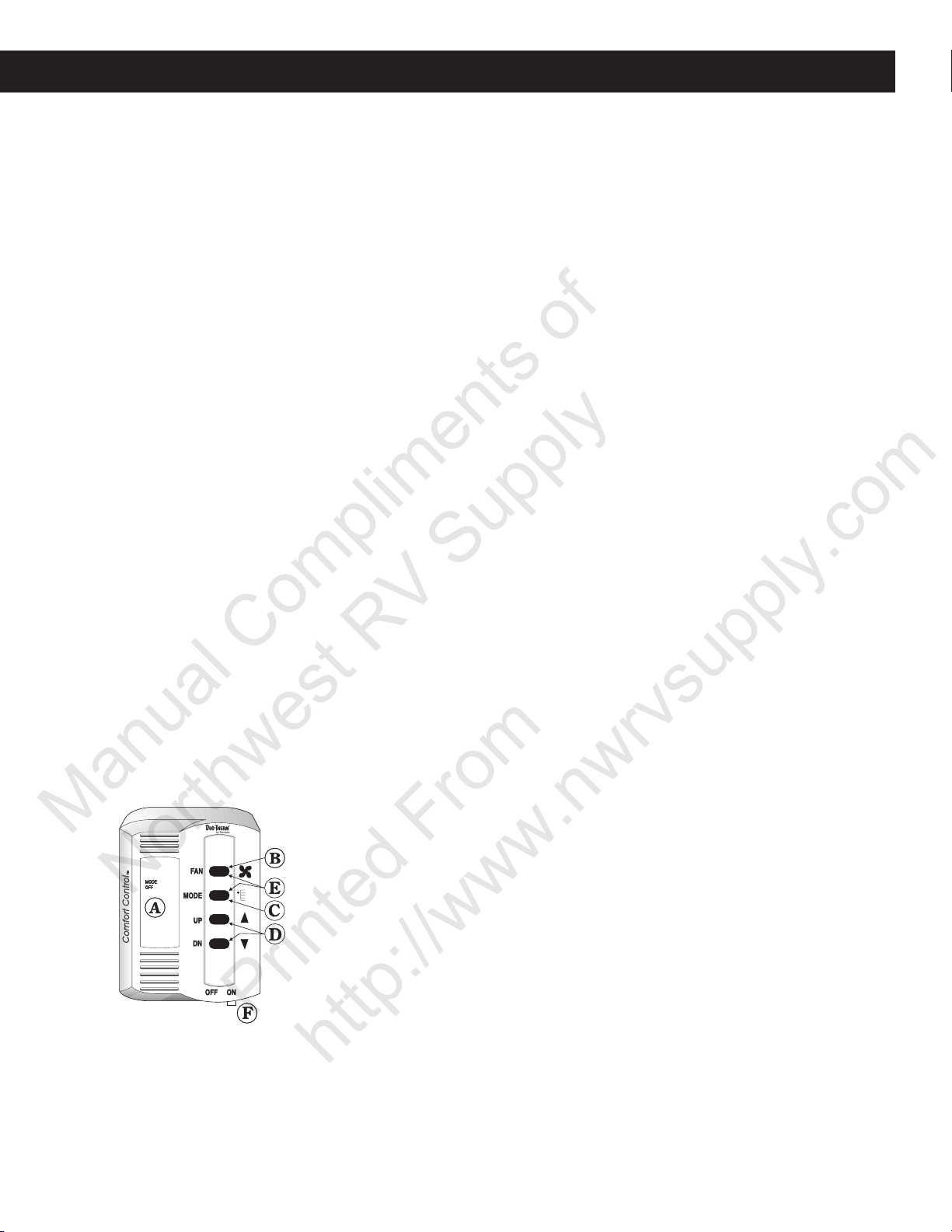
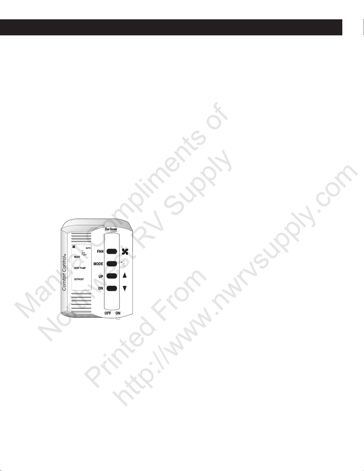
B1d. Comfort Control Center
The Comfort Control Center has been designed for you to
easily operate all the air conditioning and gas heating appliances found in your vehicle from one location.
In order to familiarize yourself with the operation of the
Comfort Control Center, the following diagram along with
FIG. B4
A. Liquid Crystal Display
the accompanying text will explain all the functional characteristics of the system.
Liquid Crystal Display - The Comfort Control Center is
equipped with a liquid crystal display (LCD) that identifies
the mode of operation, the temperature set-point, the zone
identification and the fan speed. The Comfort Control Center is designed to accept and control many varied air con-
B. Fan Speed Selector Button
C. Mode Selector Button
D. Temperature Selector Buttons
E. Zone and Stage Selector
F. On/Off Switch
ditioning and gas heating appliances. When you begin to
first operate the Comfort Control Center, you will see that
the LCD readout will only show the options available based
on the appliances installed on your vehicle. An incandescent light will illuminate the LCD area when a selector button is pushed for easy reading at all times. See FIG. B4.
Fan Speeds - Possible available fan speeds are: LOW,
MEDIUM, HIGH and AUTO. To select the desired fan speed,
momentarily depress the FAN push button. You will need
to continue to depress and release the FAN button until the
desired fan speed is shown in the LCD readout area of the
Comfort Control Center. See FIG. B4.
Mode Selector Button - Modes of operation available are:
OFF, FAN ONLY, COOL, HEAT PUMP, FURNACE, STAGE
and HEAT STRIP. Remember, the LCD readout will only
show the options available based on the appliances installed
on your vehicle. To select the mode of operation, momentarily depress the MODE push-button. You will need to
continue to depress and release the button until the desired mode is shown in the LCD readout area on the Comfort Control Center. See FIG. B4
To determine the Comfort Control Center options available
to you, depress and release the MODE push-button until it
goes through all selections. See FIG. B4
Temperature Selector Buttons - The temperature setpoint range is from 40° to 99° Fahrenheit. Determination
of Fahrenheit or Celsius standard is done at the time of
your manufacturer’s installation of the Comfort Control
Center. To set the temperature at your comfort level, simply depress and release the UP or DN push-button until the
desired temperature is shown in the LCD readout area of
the Comfort Control Center. See FIG. B4
Zone and Stage Selector Buttons - A ZONE is also es-
tablished at the time of installation of the Comfort Control
Center. If you have one air conditioner, you will have one
ZONE. If the vehicle has more than one cooling system,
depending on the manufacturing installation, you may have
2, 3 or 4 ZONES. Zones are defined and preset by the
manufacturer. A zone is an area of cooling/heating which
is controlled independently within that area, and regulated
at the Comfort Control Center. A typical example of a two
zone application would be a vehicle with two air conditioning systems, one in the front area (living room, kitchen)
and one in the back section (bedroom and bath). The front
area could be established as ZONE 1 and the back section
ZONE 2. You can select the desired temperature and fan
speeds for each zone independently, thereby keeping your
bedroom cooler than the front portion of the vehicle. To
determine the number of established zones in the vehicle,
simultaneously depress the FAN and MODE push-buttons.
ZONE 1 will be the first Zone to appear in the LCD readout.
Continue to depress and release these buttons until you
see ZONE 1 reappear. See FIG. B4.
16
B1d. Comfort Control Center
Manual Compliments of
Northwest RV Supply
Printed From
http://www.nwrvsupply.com
Section B - Operation, cont’d.
ON/OFF Switch - The ON/OFF switch is located on the
lower right hand edge of the Comfort Control Center. Move
the lever from side to side to change status. See FIG. B5.
General Information
The ability of the air conditioner to maintain the desired
inside temperature depends on the heat gain of the RV.
Some preventative measures taken by the occupants of
the RV can reduce heat gain and improve the performance
of the air conditioner. During extremely high outdoor temperatures, the heat gain of the vehicle may be reduced by:
1. Parking the RV in a shaded area.
2. Using window shades (blinds and/or curtains).
3. Keeping windows and doors shut or minimizing usage.
4. Avoiding the use of heat producing appliances.
Starting the air conditioner early in the morning and giving
it a “head start” on the expected high outdoor ambient will
greatly improve its ability to maintain the desired indoor
temperature.
The manufacturer of this air conditioner will not be responsible for damage caused by condensed moisture on ceilings or other surfaces. Air contains moisture and this moisture tends to condense on cold surfaces. When air enters
the RV, condensed moisture may appear on the ceiling,
windows, metal parts, etc. The air conditioner removes
this moisture from the air during normal operation. Keeping doors and windows closed when the air conditioner is
in operation will minimize condensed moisture on cold surfaces.
This equipment must be serviced by qualified personnel
and some states require these people to be licensed.
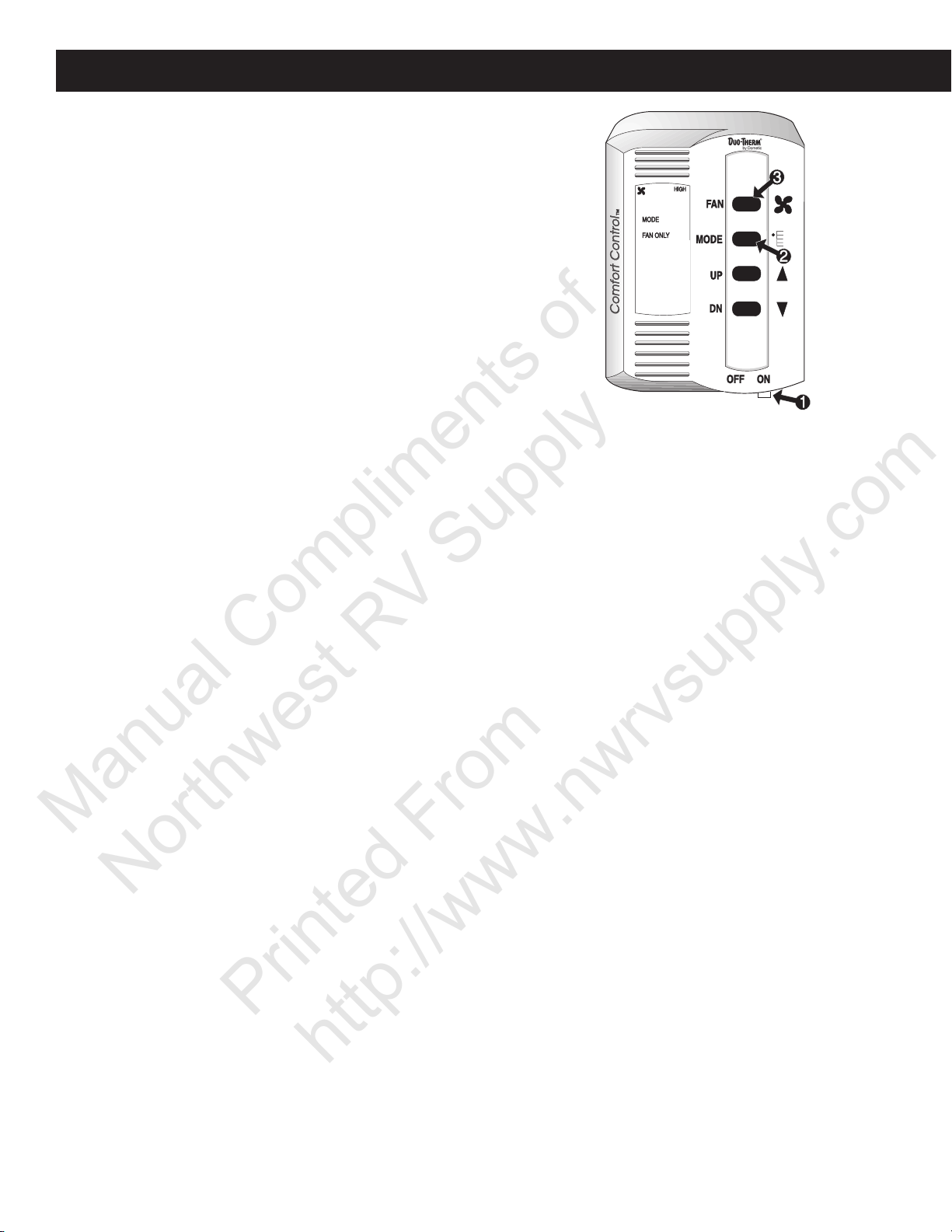
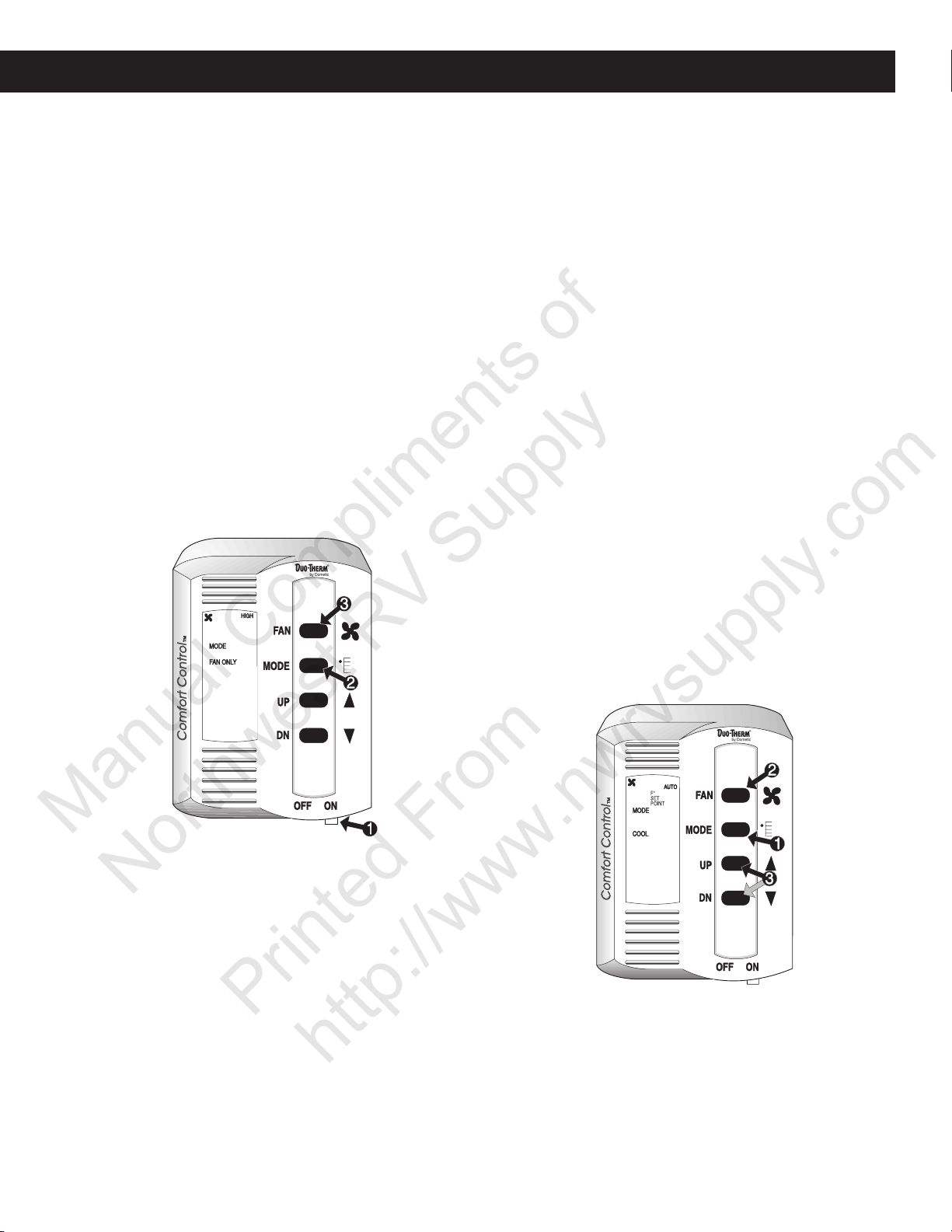
Fan Only Mode of Operation - See FIG. B4 & B5
1. Begin by placing the power switch on the lower right
hand edge of the Control Center in the ON position.
To do this, simply move the lever to the right.
2. Momentarily depress and release the MODE push-
button until the FAN ONLY indicator on the Liquid
Crystal Display (LCD) is illuminated.
3. Momentarily depress and release the FAN push-
button until the desired fan speed indicator (LOW, MED,
HIGH, AUTO) is illuminated. If your vehicle is equipped
with a heat pump or a dual basement air conditioning
system, your selection choice will be LOW, HIGH or
AUTO.
4. After approximately 5 seconds, the selected fan speed
will come on. The MODE and FAN speed you have
selected will remain shown in the LCD area of the Control Center until you change your selection.
5. If the vehicle contains more than one ZONE, depress
the FAN and MODE push-buttons simultaneously to
select ZONE 2, and repeat procedures from step two
above. Repeat entire procedure for each additional
zone.
FIG. B5
Cooling Mode Operation - See FIG. B4 & B5
(To set cooling temperatures and fan speeds on Duo-Therm
Air Conditioners and the cooling mode of Duo-Therm Heat
Pumps.)
1. Momentarily depress and release the MODE
push-button until the COOL indicator on the LCD is
illuminated.
2. Depress and release the FAN push-button to select
your desired fan speed.
3. Depress and release the UP push-button to increase
the temperature or the DN push-button to decrease
the desired temperature. The final selected SETPOINT
will be displayed in the LCD area of the Comfort Control Center.
4. After a delay of approximately 2 minutes the air
conditioner’s compressor will come on and the cooling
process will begin. Once the room temperature
reaches the selected SETPOINT, the compressor will
cycle off. Once the Comfort Control Center senses the
need for cooling, the compressor will restart in approximately two minutes. At this point, the fan will either:
a. continue to operate in the single selected fan speed
or,
b. cycle OFF and ON with the compressor if the AUTO
fan speed has been selected.
If the vehicle has a dual basement air conditioner or
dual heat pump system, the word STAGE (see stage
operation, page 20) will be illuminated. Both of these
units operate in two different stages, and the word
STAGE will show when the second stage operation has
been selected. To select the second stage, simultaneously depress the FAN and MODE push-buttons.
See FIG. B4 & B5.
17
Section B - Operation, cont’d.
Manual Compliments of
Northwest RV Supply
Printed From
http://www.nwrvsupply.com
B1d. Comfort Control Center
Fan Only Mode of Operation - See FIG. B4 & B6
1. Begin by placing the power switch on the lower right
hand edge of the Control Center in the ON position.
To do this, simply move the lever to the right.
2. Momentarily depress and release the MODE
push-button until the FAN ONLY indicator on the Liq-
uid Crystal Display (LCD) is illuminated.
3. Momentarily depress and release the FAN pushbutton until the desired fan speed indicator (LOW, MED,
HIGH, AUTO) is illuminated. If your vehicle is equipped
with a heat pump or a dual basement air conditioning
system, your selection choice will be LOW, HIGH or
AUTO.
4. After approximately 5 seconds, the selected fan speed
will come on. The MODE and FAN speed you have
selected will remain shown in the LCD area of the Control Center until you change your selection.
5. If the vehicle contains more than one ZONE, depress
the FAN and MODE push-buttons simultaneously to
select ZONE 2, and repeat procedures from step two
above. Repeat entire procedure for each additional
zone.
FIG. B6
Cooling Mode Operation
(To set cooling temperatures and fan speeds on Duo-Therm
Air Conditioners and the cooling mode of Duo-Therm Heat
Pumps.) See FIG. B7.
1. Momentarily depress and release the MODE
push-button until the COOL indicator on the LCD is
illuminated.
2. Depress and release the FAN push-button to select
your desired fan speed.
3. Depress and release the UP push-button to increase
the temperature or the DN push-button to decrease
the desired temperature. The final selected SETPOINT
will be displayed in the LCD area of the Comfort Control Center.
4. After a delay of approximately 2 minutes the air
conditioner’s compressor will come on and the cooling process will begin. Once the room temperature
reaches the selected SETPOINT, the compressor will
cycle off. Once the Comfort Control Center senses the
need for cooling, the compressor will restart in approximately two minutes. At this point, the fan will either:
a. continue to operate in the singe selected fan speed
or,
b. cycle OFF and ON with the compressor if the
AUTO fan speed has been selected.
5. If the vehicle contains more than one ZONE, depress
the FAN and MODE push-buttons simultaneously to
select ZONE 2, and repeat procedures from Step 1.
Repeat entire procedure for each additional zone.
Note: If set point is too low, the inside could freeze up.
FIG. B7
72
18
B1d. Comfort Control Center
Manual Compliments of
Northwest RV Supply
Printed From
http://www.nwrvsupply.com
Section B - Operation, cont’d.
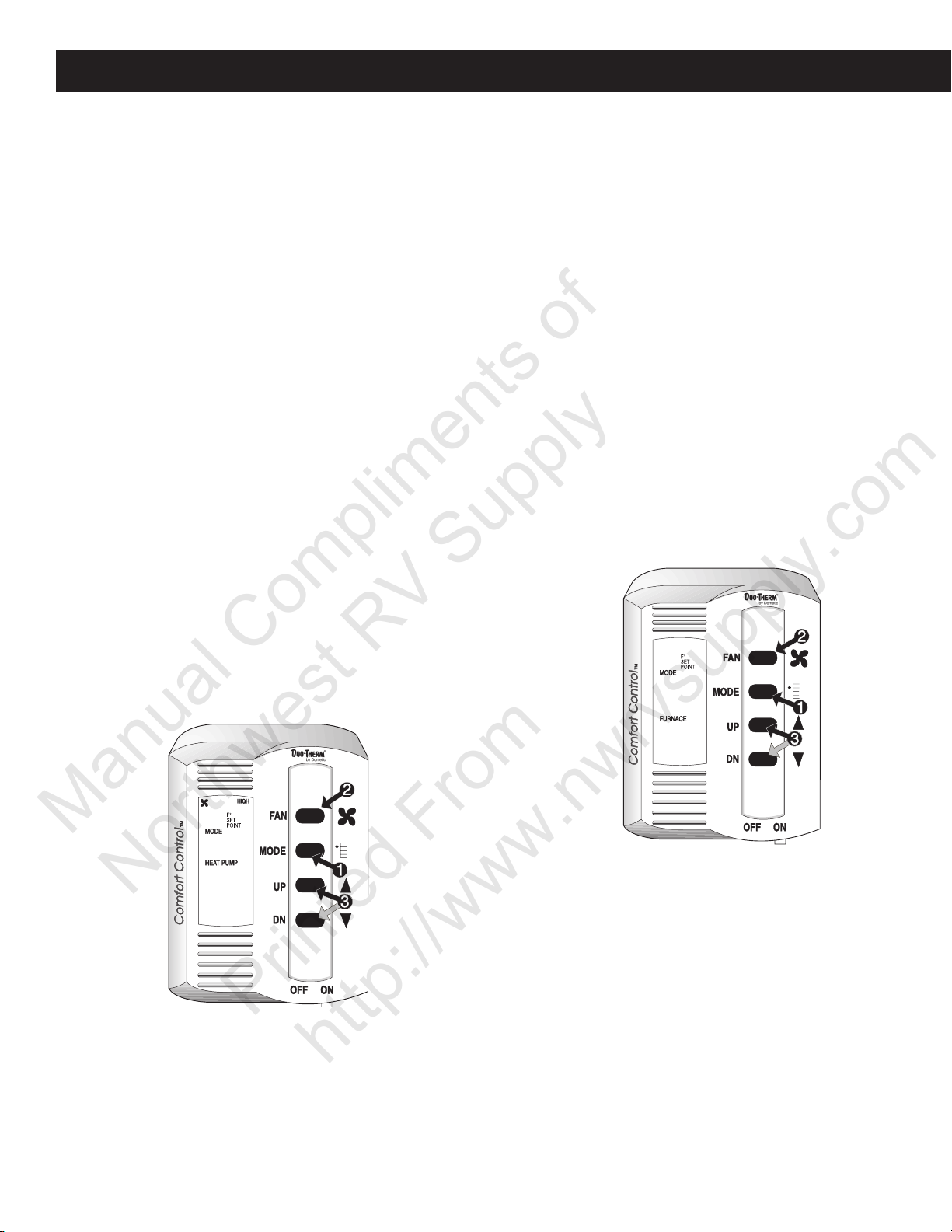
Heat Pump Operation
(To set heating temperatures for vehicles equipped with a
Duo-Therm rooftop or basement heat pump, see “Cooling
Mode Operation”.) See FIG. B8.
1. Momentarily depress and release the MODE
push-button until the HEAT PUMP indicator on the LCD
is illuminated.
2. If you have not previously set your fan speed, you may
do so by depressing and releasing the FAN pushbutton to select.
3. Depress and release the UP push-button to increase
the temperature or the DN push-button to decrease
the desired temperature. The final selected SETPOINT
will be displayed in the LCD area of the Comfort Control Center.
4. After a delay of approximately 2 minutes the heat
pump’s compressor will come on and the heating process will begin. Once the room temperature reaches
the selected SETPOINT, the compressor will cycle off.
Once the Comfort Control Center senses the need for
heating, the compressor will restart in approximately
two minutes. At this point, the fan will either:
a. continue to operate in the single selected fan speed
or,
b. cycle OFF and ON with the compressor if the AUTO
fan speed has been selected.
5. If the vehicle contains more than one ZONE, depress
the FAN and MODE push-buttons simultaneously to
select ZONE 2, and repeat procedures from Step 1
above. Repeat entire procedure for each additional
zone.
Furnace Mode Operation
(If the vehicle is equipped with a gas furnace connected to
the Comfort Control Center.) See FIG. B9
1. Momentarily depress and release the MODE
push-button until the FURNACE indicator on the LCD
is illuminated.
2. The Heat Pump fan does not operate in the FURNACE
mode.
3. Depress and release the UP push-button to increase
the temperature or the DN push-button to decrease
the desired temperature. The final selected SETPOINT
will be displayed in the LCD area of the Comfort Control Center.
4. The Duo-Therm heat pump system will not operate
when the Comfort Control System is in the FURNACE
mode. For cooling, change MODE to COOL.
5. If the vehicle contains more than one ZONE, depress
the FAN and MODE push-buttons simultaneously to
select ZONE 2, and repeat procedures from Step 1
above. Repeat entire procedure for each additional
zone.
Note: When furnace mode is selected in any Zone, all heat
pump units will terminate operation.
FIG. B9
68
FIG. B8
68
19
Section B - Operation, cont’d.
Manual Compliments of
Northwest RV Supply
Printed From
http://www.nwrvsupply.com
B1d. Comfort Control Center
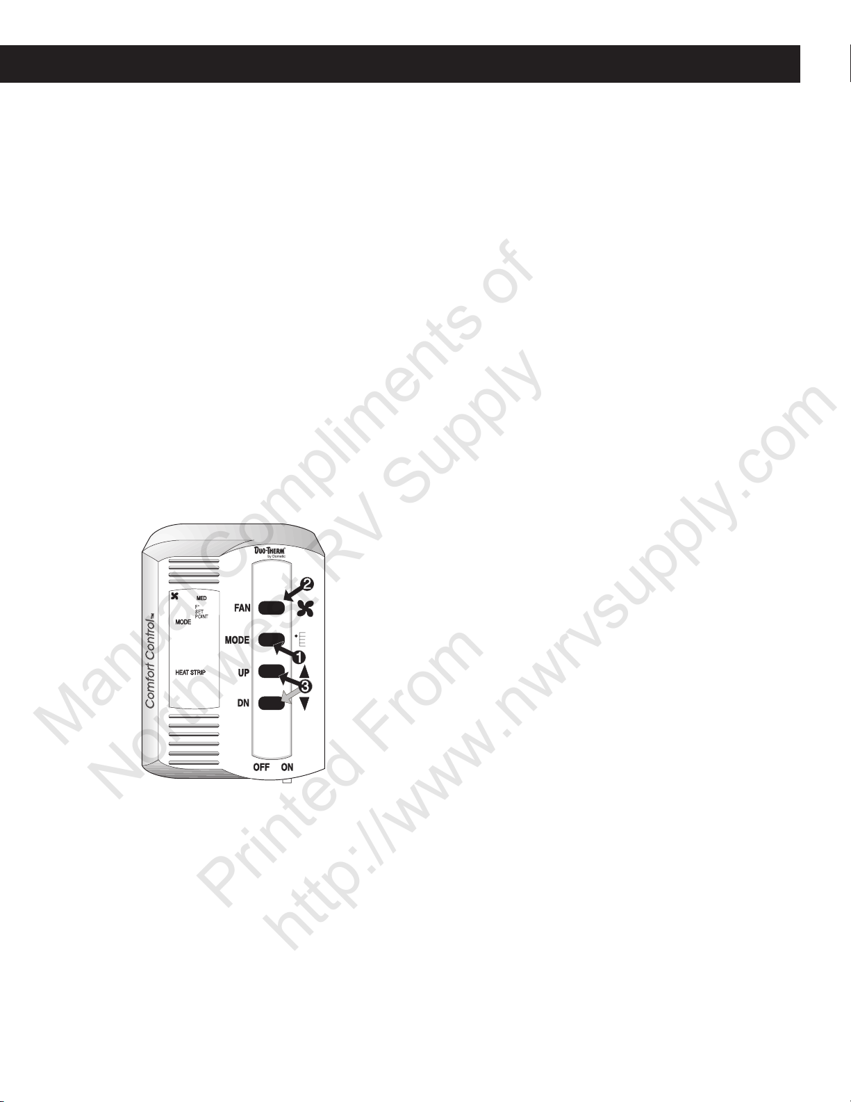
Heat Strip Mode Operation - See FIB. B10
(For Duo-Therm air conditioners with an electric heat strip.)
1. Momentarily depress and release the MODE
push-button until the HEAT STRIP indicator on the LCD
is illuminated.
2. The fan will operate in LOW, MED or AUTO. You will
not be able to select HIGH speed when in the HEAT
STRIP mode. Depress and release the FAN pushbutton to select desired speed.
3. Depress and release the UP push-button to increase
the temperature or the DN push-button to decrease
the temperature. The final selected SETPOINT will be
displayed in the LCD area of the Comfort Control Center.
4. The electric heat strip will cycle ON and OFF per the
temperature SETPOINT displayed. The fan will either:
a. continue to operate in the selected fan speed or,
b. cycle OFF and ON with the heat strip if the AUTO
fan speed has been selected.
5. If the vehicle contains more than one ZONE, depress
the FAN and MODE push-buttons simultaneously to
select ZONE 2, and repeat procedures from Step 1
above. Repeat entire procedure for each additional
zone.
FIG. B10
HEAT PUMP MODE - When HEAT PUMP mode is
selected, the fan will automatically run in the LOW
speed.
HEAT STRIP MODE - When HEAT STRIP mode is
selected, the fan will automatically run in the LOW
speed.
FAN ONLY MODE - In the FAN ONLY mode, the fan
automatically runs in the LOW speed.
Refrigerant Compressor Time Delay
A time delay of approximately two minutes occurs any time
the compressor is required to begin the cooling or heat
pump cycle.
Power Interruption
In the event that power to the air conditioner or control is
interrupted, the system will restart with the same settings
you have previously set.
Zone Control
The Duo-Therm Comfort Control Center will operate cooling and heating appliances which the vehicle manufacturer
has designed to heat or cool different areas (ZONES) of
your RV. The Comfort Control Center will advise you if the
vehicle has multiple ZONES, by showing ZONE 1, 2, 3 or
4 in the LCD readout.
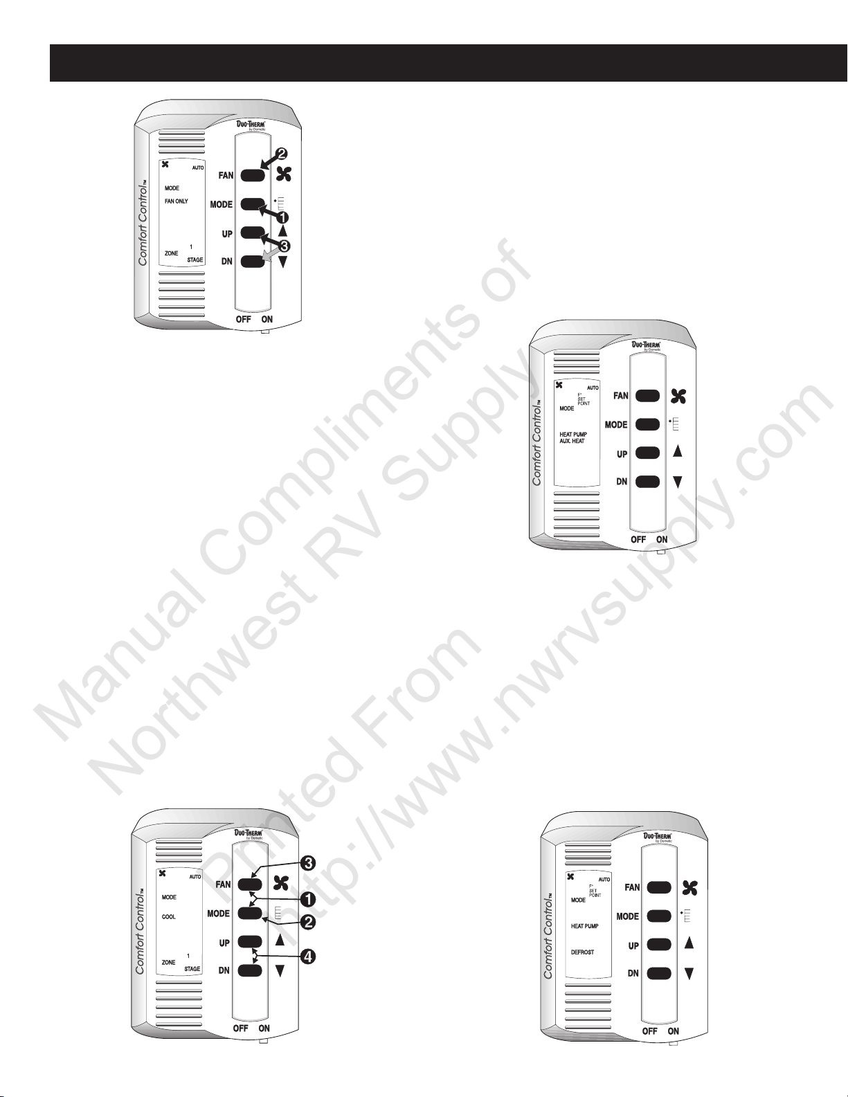
Stage Control Operation
If the vehicle is equipped with a Duo-Therm Dual Base-
72
Auto Fan
When AUTO FAN is selected, the fan speed will be deter-
mined by the mode you are in.
COOL MODE - In the COOL mode, which is the air
conditioning mode, the fan will automatically select the
speed depending upon the difference between the temperature SETPOINT and the room temperature. When
that difference is:
8° or more The fan will operate on HIGH
4° to 8° The fan will operate on MED
4° or below The fan will operate on LOW
ment Air Conditioner or a Dual Basement Heat Pump, you
have an air conditioning system that is designed to optimize comfort and running efficiencies. This is accomplished
by providing an on-demand secondary stage of operation.
Note: The primary stage will continue to operate even if
there isn’t electrical power available to run the second stage.
The Comfort Control Center simplifies this operation by
allowing you to set the primary temperature set-point and
the differential temperature set-point which activates the
secondary stage. After turning on your Comfort Control
Center, perform the following steps to set and activate the
stage control operation. See FIG. B11.
1. Momentarily depress the MODE push-button until the
desired mode of operation is selected. (FAN ONLY,
COOL, HEAT PUMP)
2. Momentarily depress the FAN push-button until the desired fan speed indicator is illuminated (LOW, HIGH,
AUTO)
20
B1d. Comfort Control Center
Manual Compliments of
Northwest RV Supply
Printed From
http://www.nwrvsupply.com
Section B - Operation, cont’d.
FIG. B11
3. Momentarily depress the UP and DN push-button until
the desired room temperature set-point is displayed.
This completes the setup for the primary stage of the Dual
Basement Air Conditioner or Dual Basement Heat Pump.
Next, you will set up the secondary stage.
To Set Up the Secondary Stage
1. Simultaneously depress and release the FAN and
MODE push-buttons until the STAGE indicator on the
LCD is illuminated. See FIG. B12.
2. Momentarily depress the MODE push-button until the
desired mode of operation for the second stage is selected (FAN ONLY, COOL, HEAT PUMP). Normally,
the mode of operation is the same as the primary stage.
3. Momentarily depress the FAN push-button until the desired fan speed indicator is illuminated (LOW, HIGH,
AUTO).
4. Momentarily depress the UP or DN push-button to set
the desired differential temperature setpoint (0°F to
10°F). The secondary stage will run once the actual
room temperature reaches the differential temperature
setpoint. Example: Desired room temperature setpoint
for the primary stage in the COOL MODE is set at 72°F;
differential temperature setpoint is set at 5°F. The secondary stage will activate when the actual room temperature reaches 77°F (72°F + 5°F), and will continue
to operate until the room once again becomes 72°F.
Aux. Heat - See FIG. B13
When in the HEAT PUMP mode, if the outside ambient
temperature is measured to be below 24°F, the control will
automatically select the FURNACE operation. When this
happens, the AUX. HEAT and the HEAT PUMP indicators
on the LCD will illuminate. Once the outside ambient temperature is measured above 34°F, the control will return to
the HEAT PUMP operation. If your vehicle does not contain a furnace, and you have a Duo-Therm Heat Pump,
once the outside ambient temperature goes below 24°F,
the system will shut down until the outside temperature
reaches 34°F, at which time the Heat Pump will resume
operation.
FIG. B13
72
Defrost Cycle - See FIG. B14
This cycle is active during HEAT PUMP operation and al-
lows the heat pump to operate down to 24°F. When the
outside ambient temperature is less than 42°F and greater
than 24°F, a defrost timing cycle will begin. The defrost
timing cycle will allow operation of the heat pump for 40
minutes. The fan will the be shut off, the refrigerant flow
reversed and run for 4-1/2 minutes, this is the DEFROST
cycle. The refrigerant flow will then be returned to normal
and after a 30 second delay, will continue until the temperature is greater than 42°F or until the temperature becomes less than 24°F, at which time the furnace will activate. (See Aux. Heat). During the defrost cycle, the DE-
FROST indicator on the LCD shall be illuminated.
FIG. B12
FIG. B14
05
21
72
Section B - Operation, cont’d.
Manual Compliments of
Northwest RV Supply
Printed From
http://www.nwrvsupply.com
Reset
If the Comfort Control Center is not operational, inadequate
data or no functions occur, reset the Comfort Control Center to factory settings. When a reset procedure is done, all
previous program memory is removed. The factory setting
of 72°F for cooling mode and 68°F for heating modes are
entered.
To initiate a RESET, do the following in the order listed:
1. Turn control on to ensure annunciator data and light
are present. If data and light are present, continue to
next step.
2. Depress MODE switch to activate annunciator light.
3. Simultaneously depress the bottom two buttons (temperature UP and DOWN) and hold.
4. While holding these buttons down, depress the MODE
button once and release.
5. Release the two buttons previously held down.
6. Depress the MODE button once again.
7. At this time the light should extinguish, and the mode
should register “OFF”. If not, repeat Steps 2 through 6.
8. Retest system ensuring that all functions are present
and operational.
FIG. B15
72
B2. Heat Pump
General Information
The roof-top heat pump was designed to operate in a MILD
GEOGRAPHICAL AREA for heating where the heat loss is
minimal. The heat pump was designed to operate down to
an outside ambient temperature of 40°F. As long as the
temperature remains below 40 degrees, the main furnace
will heat your home. As the outside temperature increases
to 45°F., the outdoor thermostat switches back to the heat
pump circuit.
Note: Model 59126.501 does not have an outdoor thermostat. When outdoor temperature is at or below 40°F., use
the main furnace to heat your home.
The advantages of the heat pump are:
1. User friendly; only one unit for both heating and cooling;
2. Heat pump heating uses campsite electrical hookup
and saves on trips to refill L.P. tanks;
3. When used in mild climates where the outdoor temperature range is 40 degrees or higher, an LP furnace
is not needed.
The heat pump operates in two different modes; cooling
and heating.
The same mechanism is used for both cycles, but the travel
or flow of refrigerant is reversed to change from cooling to
heating. The items used to accomplish this are a compressor, an inside coil, an outside coil, capillary tube or tubes
(the metering device/s), a series of copper lines (refrigerant grade tubing), a reversing valve, an air movement system (motor and wheel or blades), and refrigerant (R22).
The Cooling Mode
To cool the air inside a structure, heat is removed from the
inside air and released to the outside air or ambient.
To accomplish this, first air flow is established to pass over
both coils (inside and outside). Next, a refrigerant cycle is
established to cause refrigerant (R22) to flow through both
coils.
The refrigerant cycle starts at the compressor. Its function
is to take the low pressure R22 vapor and discharge it as
high pressure vapor. As the refrigerant (R22) is compressed, it gives off heat causing the discharge line to be
quite warm or hot to the touch in hot weather.
The R22 high pressure vapor leaves the compressor
through the discharge line and enters the reversing valve.
The reversing valve routes the high pressure vapor to the
outside coil. In the cooling mode, the outside coil is a condenser coil.
The high pressure R22 vapor enters the outside coil (condenser). Here it is cooled and condensed into liquid R22
by passing through the coil. The heat removed from the
refrigerant is expelled to the outside air. The refrigerant
22
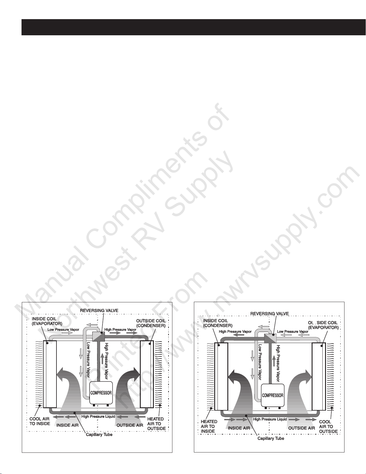
B2. Heat Pump
Manual Compliments of
Northwest RV Supply
Printed From
http://www.nwrvsupply.com
Section B - Operation, cont’d.
leaves the outside coil as high pressure liquid.
As the high pressure liquid R22 leaves the outside coil
(condenser) it passes through the small capillary tube or
tubes. This is the metering or flow control device in the
sealed system. It determines the amount and force of which
the R22 enters the inside coil. It is imperative that the
capillary tube’s length and diameter not be altered. If the
tube is altered, the unit will not operate as efficiently as it
should.
The high pressure liquid R22 enters the inside coil in a
controlled amount from the capillary tube. When the liquid
enters the low pressure atmosphere of the inside coil
(evaporator) it evaporates into vapor. When the evaporative process takes place, heat is removed from the air flowing through the inside coil (evaporator). The air with the
heat removed is returned to the inside of the structure via
the air movement system (blower assembly).
From the inside coil (evaporator), the low pressure refrigerant (R22) vapor returns to the reversing valve. The reversing valve routes the low pressure vapor to the compressor through the suction line to start the cooling process again.
The Heating Mode
To heat the air inside a structure, heat is removed from the
outside air or ambient and released to the inside air.
To accomplish this, first air flow is established to pass over
both coils (inside and outside), Next, a refrigerant cycle is
established to cause the refrigerant (R22) to flow through
the coils.
The refrigerant cycle starts at the compressor. Its function
is to take the low pressure R22 vapor and discharge it as
high pressure vapor. As the refrigerant (R22) is compressed, it gives off heat causing the discharge line to be
quite warm to the touch.
The R22 high pressure vapor leaves the compressor
through the discharge line and enters the reversing valve.
The reversing valve routes the high pressure vapor to the
inside could. In the heating mode the inside coil is a condenser coil.
The high pressure R22 vapor enters the inside coil (condenser). Here it is cooled and condensed into liquid R22
by passing through the coil. The heat removed from the
refrigerant is expelled to the inside air. The refrigerant leaves
the inside coil as high pressure liquid.
As the high pressure liquid R22 leaves the inside coil (condenser) it passes through the small capillary tube or tubes.
This is the metering or flow control device in the sealed
system. It determines the amount and force of which the
R22 enters the outside coil.
It is imperative that the capillary tube’s length and diameter
not be altered. If the tube is altered, the unit will not operate
as efficiently as it should.
FIG. B16
COOLING MODE
FIG. B17
HEATING MODE
23

Section B - Operation, cont’d.
Manual Compliments of
Northwest RV Supply
Printed From
http://www.nwrvsupply.com
B2. Heat Pump
The high pressure liquid R22 enters the outside coil in a
controlled amount from the capillary tube. When the liquid
enters the low pressure atmosphere of the outside coil
(evaporator) it evaporates into vapor. When the evaporative process takes place, heat is removed from the air flowing through the outside coil (evaporator). The air with the
heat removed is returned to the outside air (ambient) via
the air movement system (blower assembly).
From the outside coil (evaporator), the low pressure refrigerant (R22) vapor returns to the reversing valve. The reversing valve routes the low pressure vapor to the compressor through the suction line to start the heating process again.
Operating instructions can change from one model to another.
Be sure you are familiar with the proper operating instructions for the specific model of heat pump you are diagnosing. An installation and operating manual is packaged with
each heat pump system.
Fan Operation:
This will circulate the air in your RV without cooling or heating. There are two positions: HIGH FAN or LOW FAN to
select from, depending upon personal choice.
Heating Operation
Note: This heat pump will not replace a furnace for heating
your RV in cold weather. The intent is to remove the chill
on cool days or mornings. When the outdoor temperature
is below 40°F., the outdoor thermostat will shut down heat
pump operation.
1. Turn the selector switch to “HEAT PUMP”;
2. The Fan and Compressor will come on and begin heating.
3. When desired temperature level in RV is reached, the
blower will run continuously to circulate air and maintain an even temperature. The compressor will cycle
as required to maintain selected temperature.
Off Position
This position turns the unit off.
B2a. Mechanical Controls
This type of heat pump has an air distribution box that has
a mechanical selector switch and thermostat installed in it.
Note: Remember to check the installation and operating
instructions for the specific model you are diagnosing.
Controls
The Selector Switch has eight positions including “OFF”.
This controls fan speed, heating mode and cooling modes.
The Thermostat controls the temperature range from 65°F.
on the coldest side to 90°F. on the warmest side. In the
cooling/heating mode, the compressor ON/OFF is controlled by the thermostat setting.
Cooling Operation
Set the thermostat at the desired temperature level. Select
the fan speed that best satisfies your needs:
a. HIGH COOL: Selected when maximum cooling and
dehumidification is required.
b. LOW COOL: Selected when room is at desired com-
fort level and needs to be maintained. Normally this
speed is used for nighttime operation.
Note: The blower runs continuously to circulate air and
maintain an even temperature. The compressor will come
on when cooling is required to maintain the selected temperature level.
After shutting the heat pump down with either selector switch or thermostat, wait at
least two (2) minutes before restarting. This
allows the refrigerant pressure to equalize
and compressor to restart easily.
B2b. Bimetal Relay Controls
This type of air conditioner has a wall mounted bimetal thermostat and a relay board that replaces the mechanical
switch and thermostat on the mechanical units and replaces
the main board and control board on the electronic units.
See FIG. B18.
Note: Remember to check the installation and operating
instructions for the specific model of air conditioner you
are diagnosing.
Bimetal Cooling Operation
Place the Temperature Set Lever (1) to desired temperature level (located at top of thermostat). Select fan speed
that best satisfies your needs: (upper right switch at bottom of thermostat) (4).
a. High Speed: Selected when maximum cooling and
dehumidification are required.
b. Low Speed: Selected when RV reaches desired com-
fort level and needs to be maintained. Normally this
speed is used for nighttime operation.
Select Auto/ON Switch (2) operation as follows: (Lower right
switch at bottom of thermostat)
a. Auto Position: Air conditioner fan runs whenever cool-
ing is required and stops whenever cooling is not re-
quired.
b. On Position: Air conditioner fan runs continuously to
circulate air in RV.
Set the system switch to cool position. (Located at lower
left side of thermostat)
The air conditioner will now come on when cooling is required and cycle off when the temperature level selected is
reached.
24

B2. Heat Pump
Manual Compliments of
Northwest RV Supply
Printed From
http://www.nwrvsupply.com
Section B - Operation, cont’d.
FIG. B18
1
B2c. Analog Control System
In order to familiarize yourself with the operation of the
Analog Control System, the following diagrams along with
the accompanying text will explain all the functional characteristics of the system.
FIG. B19
4
3
2
SYSTEM
COOL
OFF
FURNACE
HEAT PUMP
COOL
FURNACE
HEAT PUMP
HEAT STRIP
Wait at least two (2) minutes before restarting the air conditioner after shutting off with
either the Heat/Off/Cooling Switch or the Temperature Set Lever. This allows the refrigerant pressure in the air conditioner to equalize and will allow the compressor to restart
easily.
Heating Operation
(If furnace is connected to thermostat)
Set Temperature Set Lever (1) to desired temperature level
(located at top of thermostat). Set the System Switch to
heat position (located at lower left side of thermostat(.
The furnace will now come on then heat is required and
cycle off when temperature level selected is reached.
Special Feature
When thermostat System Switch is in the OFF or HEAT
position and Auto/On Switch is in the ON position, the air
conditioner fan will run continuously to circulate the air inside the RV.
Heat Pump Operation - See FIG. B18
1. Set the Temperature Set Lever (1) to desired temperature setting.
2. Set the System Switch (3) to heat pump position.
3. Move the FAN Auto/On Switch (2):
a. Auto Position: Unit fan runs whenever heat is re-
quired and stops whenever heating is not required.
b. ON Position: Unit fan runs continuously to circu-
late air in RV.
4. Select the desired fan speed by moving the fan speed
switch (4) to :
a. High speed: Selected for maximum air flow. The
discharge air will feel cool.
b. Low speed: Selected normally for heat pump op-
eration. The lower air flow allows it to feel warmer.
1. Temperature Set Lever
2. Fan Auto/On Switch
3. System Switch
4. Fan High/Low Switch
Analog Control Cooling Operation - See FIG. B19
1. Place the Temperature Set Lever (1) to desired temperature level.
2. Select desired fan speed by moving the Fan Speed
Switch (4) to:
a. High Speed: Selected when maximum cooling and
dehumidification are required.
b. Low Speed: Selected when RV reaches desired
comfort level and needs to be maintained. Normally
this speed is used for night time operation.
3. Move the FAN Auto/On Switch (2):
a. Auto Position: Unit fan runs whenever cooling is
required and stops whenever cooling is not required.
b. ON Position: Unit fan runs continuously to circu-
late air in RV.
4. Set the System Switch to cool position.
The unit compressor will now come ON and cycle OFF
when the temperature level selected is reached.
Furnace Operation
(If furnace is connected to relay box.) - See FIG. B19
1. Set the Temperature Set Lever (1) to desired temperature setting.
2. Set the System Switch (3) to furnace position. The furnace will now come ON when heat is required and cycle
OFF when the temperature setting selected is reached.
FAN
ON
AUTO
SYSTEM
OFF
HI
LO
HEAT PUMP
3
SYSTEM
COOL
OFF
FURNACE
AUTO
90
30
80
FAN
ON
70
20
60
50
10
°C
HI
40
LO
AUTO
90
30
80
FAN
70
ON
20
60
50
10
°C
40
HI
LO
90
30
80
70
20
60
50
10
°C
40
4
2
1
25
Section B - Operation, cont’d.
Manual Compliments of
Northwest RV Supply
Printed From
http://www.nwrvsupply.com
B2. Heat Pump
Analog Control Electric Heat Pump Operation - See
FIG. B19
1. Set the Temperature Set Lever (1) to desired temperature level.
2. Set the System Switch (3) to heat pump position.
3. Move the
a. Auto Position: Unit fan runs whenever heat is re-
b. ON Position: Unit fan runs continuously to circu-
4. Select desired fan speed by moving the Fan Speed
Switch (4) to:
a. High Speed: Selected when maximum air flow is
b. Low Speed: Normally selected for heat pump op-
Continuous Blower Operation
1. Set the System Switch (3) to any position (including
“OFF”).
2. Move the FAN Auto/On Switch (2) to the ON position,
the unit fan will operate continuously at the fan speed
selected by the Fan Speed Switch (4).
3. Select desired fan speed by moving the Fan Speed
Switch (4) to:
a. High Speed: Selected when maximum air flow is
b. Low Speed: Normally selected for heat pump op-
FAN Auto/On Switch (2):
quired and stops whenever heating is not required.
late air in RV.
required. The discharge air will feel cool due to the
maximum air flow. It is normally not used for heat
pump operation.
eration, because less air movement is needed for
heat and discharge air is warmer.
required. The discharge air will feel cool due to the
maximum air flow. It is normally not used for heat
pump operation.
eration, because less air movement is needed for
heat and discharge air is warmer.
B2d. Comfort Control Center
The Comfort Control Center has been designed for you to
easily operate all the air conditioning and gas heating appliances found in your vehicle from one location.
In order to familiarize yourself with the operation of the
Comfort Control Center, see Section B1d on page 16.
Make sure that the power supply to the unit
is disconnected before performing any work
on the unit to avoid the possibility of shock
injury or damage to the equipment.
26
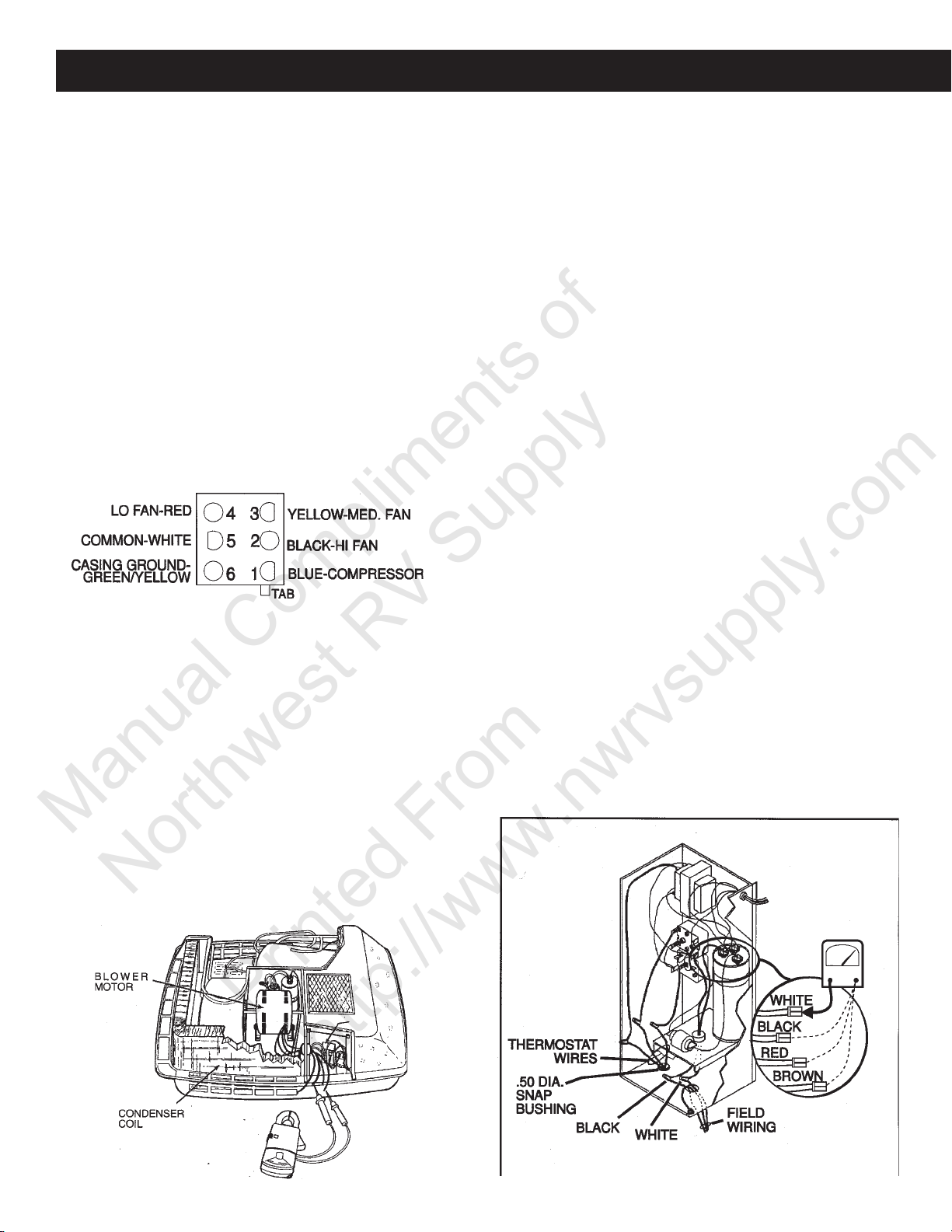
Section C - Components
Manual Compliments of
Northwest RV Supply
Printed From
http://www.nwrvsupply.com
C1. Motors
Roof Top Units - To check the motor, turn the unit circuit
breaker to OFF. With an AC volt meter, verify that the circuit has no AC volts. On most units, the wires from the
motor connect directly into a 6 or 9 pin connector. The motor
leads are white (common), black (high), red (low) and yellow (medium). Some units are 2-speed. If you are checking a 2 speed system, disregard the yellow wire. Set your
VOM to the ohms scale. You will perform a continuity test.
Check for continuity between the white wire and each of
the other wires.
Lack of continuity between the white wire and any of the
other wires indicates an open circuit and requires that the
motor be changed. Next, check for continuity between each
wire and the green/yellow wire. If you get continuity, you
have a grounded motor and it must be replaced.
On Models 620315 and 630215, the motor leads do not go
FIG. C1
into a connector. On these units, disconnect the wires from
the AC power module and do the previous tests between
the motor leads.
Single Compressor Units
The units that have a single compressor are Models:
39015.XXX
39025.XXX
39035.XXX
39045.XXX
39115.XXX
39325.XXX
39335.XXX
To check the motor, turn the unit circuit breaker OFF. With
an AC voltmeter, verify that the circuit has no AC voltage.
Next, locate the electric box and remove its cover. The motor
leads will connect to a relay or a power module board and
the run capacitor. Disconnect the motor leads.
Set your ohm meter to its highest scale for these tests.
Check for continuity between the white wire and each of
the other wire. Lack of continuity between the white wire
and any of the other wires indicates an open circuit and
requires that the motor be changed. Next, scrape some
paint off the motor casing and check for continuity between
each wire and unit casing or the motor casing. If you get
continuity between each wire and unit casing or the motor
casing. If you get continuity between any of the wires and
the motor casing, you have a grounded motor and it must
be replaced.
There are two types of motors used on these models.
One is a single-speed motor and the other is a two-speed
motor (high and low). The single speed motor has three
wires: White (common), Black (high) and Brown (capacitor). The two-speed has four wires: White (common), Black
(high), Red (low) and Brown (capacitor).
Dual Compressor Units
The units that have dual compressors are Models:
39224.601 and 39424.601
To check the motor, turn the unit circuit breaker or breakers OFF. With an AC volt meter, verify that the circuit has
no AC voltage. The wires from the motor connect to a 9-pin
connector. The motor leads are white (common - Terminal
4), black (high - Terminal 6) and red (low - Terminal 7). Set
your ohm meter to its highest scale for these tests. Check
for continuity between the white wire and each of the other
wires.
FIG. C3
FIG. C2
27
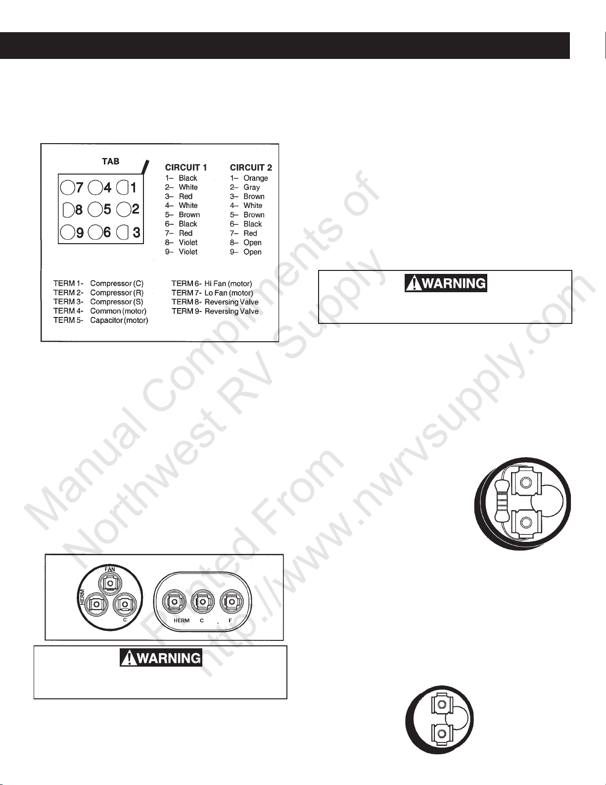
Section C - Components, cont’d.
Manual Compliments of
Northwest RV Supply
Printed From
http://www.nwrvsupply.com
Lack of continuity between the white wire and any of the
other wires indicates an open circuit and requires that the
motor be changed. Next, check for continuity between each
wire and the green/yellow wire. If you get continuity, you
have a grounded motor and it must be replaced. See FIG.
C4.
FIG. C4
Another test is the motor amperage on high speed. The
amp meter is clamped around the black (high speed) lead.
The high speed running amps of the motor should be ±1/
10 of rating plate motor amps. If amp reading is above
normal (listed on rating plate), the fan capacitor may be
defective. Verify that the fan run capacitor is of the correct
rating for the motor. See Section C2.
C2. Capacitor, Fan/Run
The run capacitor may be one of two different kings: Either
a single capacitor for the fan or compressor, or a combination capacitor for both the fan and the compressor.
The run capacitor should be checked with a capacitor tester.
Follow the tester manufacturer’s testing procedures. If one
is not available, an ohm meter may be used. Turn the air
conditioner circuit breaker OFF. See FIG. C5.
FIG. C5
the VOM meter to the highest ohm scale and connect the
probes to the capacitor terminals. The reading should rapidly move toward continuity and slowly return to infinity. You
should reverse the leads and repeat the procedure. If there
is no reading, or a prolonged reading, replace the run capacitor. The combination run capacitor has three terminals.
The terminals are marked “F”, “C” and “HERM”. To check
the combination run capacitor, follow the discharge procedures above. Again, make sure you test from “C” (common) to “F” (fan) and “C” (common) to “HERM” (compressor).
C3. Start Capacitor
The unit will have one of two types of start capacitor. One
type has a 15,000 ohm resistor between the terminals. The
other type does not have the resistor.
There may be a charge on the capacitor until
discharged.
Using an AC voltmeter set at the 500 volt scale or higher,
connect the meter leads to the terminals of the capacitor.
Start Capacitor with Resistor
The start capacitor should be checked with a capacitor
tester. Follow the tester manufacturer’s testing procedures.
If one is not available, an ohm meter may be used. Turn
the unit’s circuit breaker OFF. Disconnect the wires to the
capacitor. The start capacitor does not need to be manually discharged since it has a built-in resistor. Use only an
analog or dial-type ohm meter. Set the ohm meter to the
highest ohm scale and connect the
probes to the capacitor terminals.
The reading should show continuity
and slowly return to 15,000 ohms.
You should then reverse the leads
and check again. If there is not reading or a reading greater than 15,000
ohms, the start capacitor should be
replaced. See FIG. C6.
Start Capacitor without Resistor
FIG. C6
The start capacitor (without resistor) must be manually discharged in the same way the run capacitor was done a
There may be a charge on the capacitor until
discharged.
The run capacitor must be manually discharged. Using an
AC voltmeter set at the 500 volt scale or higher, connect
meter leads to the terminals of the capacitor. After discharging the capacitor, disconnect the wires to the capacitor. Set
moment ago. See Section C2. Check this style capacitor
the same way you would check the capacitor with the resistor. The reading will be different. The reading should show
continuity and slowly return to infinity. Reverse the leads
and check again. If there is no reading or a reading of “0”
ohms, the start capacitor should be replaced. See FIG. C7.
FIG. C7
28
 Loading...