

Duon System AUTROL Series, APT3500, AUTROL APT3200 SERIES Operation Manual
APT3500 Smart Pressure Transmitter Operation Manual M3500-E01A
* Information on this manual can be changed without an advance notice.
APT3500 Smart Pressure Transmitter
Operation Manual
DUON SYSTEM CO., LTD
Autrol
®
DUON SYSTEM Co., Ltd. http://www.autrol.com/
AUTROL Series Operation Manual : M3500-E01A

APT3500 Smart Pressure Transmitter Operation Manual M3500-E01A
ii
Duon System Co.,Ltd.

APT3500 Smart Pressure Transmitter Operation Manual M3500-E01A
APT3500 Smart Pressure Transmitter
This manual is made so that general user can help to install and operate
APT3500 Smart Pressure Transmitter efficiently.
Before handling APT3500 transmitter, all users have to be fully aware of it.
Information on this manual can be changed
Without an advance notice.
DUON SYSTEM CO., Ltd
60-31, Gasan-dong, Guemchon-gu, Seoul, Korea
Tel: +82-2-860-7900

APT3500 Smart Pressure Transmitter Operation Manual M3500-EO1G
2 DUON System Co., Ltd.
Table of Contents
Chapter 1 Introduction
1.1 Using This Manual
1.2 Overview of Transmitter
1.3 Software Compatibility
1.4 Transmitter Components
Chapter 2 Handling Cautions
2.1 Unpacking
2.2 Models and Specifications Check
2.3 Storage
2.4 Selecting the Installation Locations
2.5 Calibration on Spot after Installation
2.6 Pressure Connections
2.7 Waterproofing of Cable Conduit Connections
2.8 Restrictions on Use of Radio Transceiver
2.9 Insulation Resistance Test and Dielectric Strength Test
2.10 Installation of Explosion Protected Type Transmitters
2.11 EMC Conformity Standards
Chapter 3 Transmitter Functions
3.1 Overview
3.2 Safety Messages
3.3 Warning
3.4 Fail Mode Alarm
3.5 EEProm-Write Enable and Disable Mode Switch
3.6 Configuration of Alarm and Security Jumper Procedures
3.7 Configuration of Zero and Span Procedures
3.8 Shop Commissioning using HHT
Chapter 4 Installation
4.1 Overview
4.2 Safety Messages
4.3 Warning
4.4 Commissioning on the bench with Hand-Held Terminal
4.5 General Considerations
4.6 Electrical Considerations (Power Supply)
4.7 Wiring
4.8 Mechanical Considerations
4.9 Environmental considerations

APT3500 Smart Pressure Transmitter Operation Manual M3500-EO1G
3 DUON System Co., Ltd.
Chapter 5 On-line Operation
5.1 Overview
5.2 Safety Messages
5.3 Configuration Data Review
5.4 Check Output
5.5 Basic Setup
5.6 Detail Setup
5.7 Configuration of Information Variable
5.8 Configuration of Breakdown Diagnostics Function
5.9 Calibration
Chapter 6 Maintenance
6.1 Overview
6.2 Safety Messages
6.3 Hardware Diagnosis
6.4 Hardware Maintenance

APT3500 Smart Pressure Transmitter Operation Manual M3500-EO1G
4 DUON System Co., Ltd.
Appendix I
APT3500 Smart Pressure Transmitter
LCD Display Code
APPENDIX II
PRODUCT CERTIFICATION
APPENDIX III
Special Condition for Safe use

APT3500 Smart Pressure Transmitter Operation Manual M3500-EO1G
5 DUON System Co., Ltd.
Chapter 1 Introduction
The APT3500 Smart Pressure Transmitter are correctly calibrated at the factory before shipment. To
ensure correct and efficient use of the instrument, please read this manual thoroughly and fully
understand how to operate the instrument before operating it
① The contents of this manual are subject to change without prior notice.
② All rights reserved. No part of this manual may be reproduced in any form without DUON
System’s written permission.
③ If any question arises or errors are found, or if any information is missiong from this manual,
please inform the nearest DUON System sales office.
④ The specifications covered by this manual are limited to those for the standard type under the
specified model number break-down and do not cover custom-made instrument.
⑤ Please note that changes in the specifications, construction, or component parts of the
instrument may not immediatelty be reflected in this manual at the time of change, provided
that postponement of revisions will not cause difficulty to the user from a functional of
performance standpoint.
1-1 Using This Manual
The Chapters in this operating manual provide information on installing, operating, and maintaining
devices from the AUTROL Model APT3500 Samrt Pressure Transmitter. The Chapters are organized as
follows.
Chapter 2 Handling Cautions
Chapter 2 provides instructon on commissioning and operating Model APT3500 Smart
Pressure Transmitters. Informations on software functions, configuration parameters, and on-line
variables is also included.
Chapter 3 Transmitter Functions
Chapter 3 contains in consideration of handling Model APT3500 Smart Pressure Transmitters.
Chapter 4 Installation
Chapter 4 contains mechanical, environment consideration and electrical installation
instructions on the Model APT3500 Smart Pressure Transmitters.
Chapter 5 On-line Operation
Chapter 5 describes the configuration the parameter how to use variety of the Model
APT3500 Smart Pressure Transmitters' software fucntion and configuration. See the following list for
the details.
① Regulations of circuit's Input/Output characteristics; Sensor or Output Trim
② Changed of output characteristic; Range Configuration, Output Type, Damping,Unit
③ Changed of general data; Tag No.,Date,Message etc.
Chapter 6 Maintenance
Chapter 6 contains hardware diagnostics ,troubleshooting and maintenace task.

APT3500 Smart Pressure Transmitter Operation Manual M3500-EO1G
6 DUON System Co., Ltd.
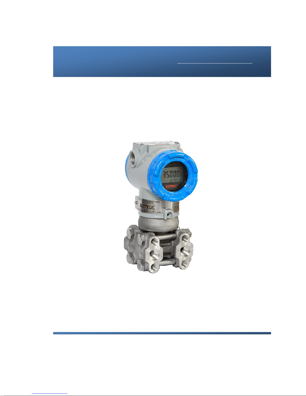
1.2 Overview of Transmitter
Autrol® Smart Pressure Transmitter based in a microprocessor is the pressure transmitter, has a
designed capacitance sensor optimized for draft measurement. APT3500 has a true draft analog range
from 4 to 20mA offering that feature that a pressure range or after convert analog range to HART
(Communication) digital signal transmit for control systems like DCS, PLC. This Model has explosion
protected type and high precision, better reliabilty and is available on digital commuication for the use
remotes communication system.
This transmitter is enabled in HART commmunication with Host, HHT (HART Hand-Held Terminal) or
PC Configurator. Thus, transmitter various variables in host is enable to be changed, configured and
tested calibrated by users. For the HART Communication between DC Power Supply and Transmitter
has to terminate 250~ 550 Ohm.
1.3 Software Compatibility
Autrol® Smart Pressure Transmitter's software is implemented and complemented if necssary. Uses of
the transmitter will not be a compatibility software is contained in the host of the HHT(ACONF312 or
275/375/475 HART Communicator). In this case contact us for software DD(Device Descriptor) to be
able to use with the transmitter, you must to use loading in HHT, etc.
There may be some differences on supported fucntions as to Firmware Revision of transmiter. This
manual is based on Firmware Revision 10. Function deviations as to firmware Revision are same as
under box
Item Function
Function Supports
Output that is affected by
set-up change
Button HART
(HHT/
SST30)
Rev.10
Basic
Set-up
Range set ● ●
Whole output excluding PV
displayed on LCD
Units set ● ● PV displayed on LCD
Damping Seccond set ● ● Whole Output
Transfer Function set ● ●
Whole output excluding PV
displayed on LCD
Low-cut set ● ●
Whole output excluding PV
displayed on LCD
Loop Test ● ● 4~20mA
Calibration
Zero Trim ● ● Whole Output
Zero Adjustment ● ● Whole Output
Full Trim ⅹ ● Whole Output
D/A Trim ⅹ ● 4~20mA

APT3500 Smart Pressure Transmitter Operation Manual M3500-EO1G
7 DUON System Co., Ltd.
Transm itter
Information
Set-up
Polling Address set ● ● 4~20mA
Setting up transmitter basic information
(Tag, Date, Descriptor, Message)
ⅹ ● -
LCD
Display
LCD mode set ● ● Whole LCD Display
Decimal Place set ● ● Whole LCD Display
LCD Engineering Mode set
(Eng Range, Eng Unit, Eng Transfer
Function…)
● ● LCD Engineering Value
Other
Button Lock set ● △ -
Master Reset ● ● Whole Output
: Supported.
ⅹ : Not Supported
: Supported but update required
APT3500 Smart Pressure Transmitter Operation Manual M3500-EO1G
8 DUON System Co., Ltd.
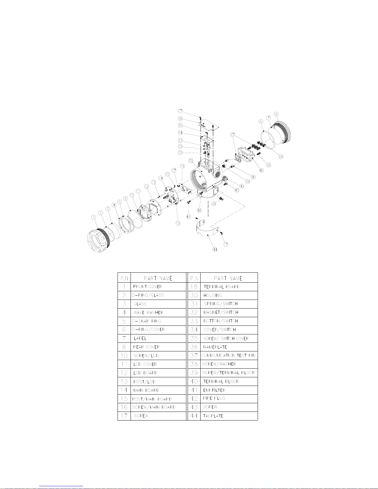
1.4 Transmitter Components
The components and figure of Autrol® Smart Pressure Transmitter is suggested on the next page.
Follow the precedure described on figure 1-1, 1-2, 1-3, 1-4, 1-5, 1-6.
Figure 1-1. Model APT3500 Transmitter Exposed View (Housing)
Figure 1-2. TRANSMITTER COMPONENTS
APT3500 Smart Pressure Transmitter Operation Manual M3500-EO1G
9 DUON System Co., Ltd.
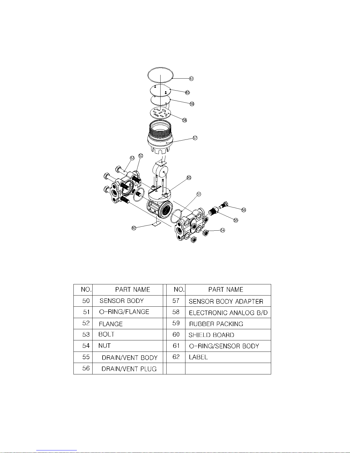
Figure 1-3. Model APT3500 Exploded View (Sensor Module-D,G,L)
Figure 1-4. TRANSMITTER COMPONENTS

APT3500 Smart Pressure Transmitter Operation Manual M3500-EO1G
10 DUON System Co., Ltd.
Chapter 2 Handling Cautions
This chapter consists of cautions for transmitter handling and storage, selection of installation
locations, insulation and explosion structure, etc.
[Quick Reference Manual]
Step Job Job Details Instrument
1 Unpacking - Unpack transmitter packing
2
Model and
Specifications
Check
- Make sure whether the delivered transmitter is same
as options attached on its nameplate
3 Storage
- Places not exposed to water, non-vibration and non-
impact area
- Ambient temperature 25 deg C and relative humidity
65% RH
4
Calibration on a
Calibration Room
- Configuration of Range, Zero/Span, Unit, Tag,
Damping Time, Transfer Function, DA Trim and other
parameters
- HHT
- Pressure
Source
(requested)
- Galvanometer
5
Installation
Locations
- Where ambient temperature is not fluctuated
- Where corrosion happens by chemical materials, etc.
- Where vibration and impact is not severe
- Where non-explosion area is matched on
explosionproof regulations
- Where maintenance is very easy
(Engineering)
6
Mechanical
Considerations
- Where transmitter can be handled easily
- Be cautious not leaking the pressure.
(Engineering)
7
Electrical
Considerations
- Connect 24 Vdc
(Power Supply is 12 Vdc – 45 Vdc)
- For HART communication, total resistance on
transmitter terminal loop should be 250 – 550 Ohm.
(Engineering)
8
Mounting and
Installation
- For mounting transmitter, an appropriate bracket
should be used.
- Transmitter should be fixed well against swing.
(Mounting and
Installation)
9
Calibration on
Spot
- Sensor Zero Trim has to be done after ten seconds,
namely, differential pressure become zero and
stabilized.
- Make sure that PV value of transmitter is zero and
current is 4 mA.
HHT or
Zero/Span
button
10 Pressure
- Do not apply the regulated differential and line
pressure.
- Close equalizing valve of 3 valve manifold, Then,
open stop valve on high and low side slowly and
simultaneously.
(Applying
pressure)
11 Operation - Make sure whether transmitter operates well or not Eye or HHT

APT3500 Smart Pressure Transmitter Operation Manual M3500-EO1G
11 DUON System Co., Ltd.
2.1 Unpacking
When moving the transmitter to the installation site, keep it in its original packaging. Then, unpack
the transmitter there to avoid damage on the way.
2.2 Models and Specifications Check
The model name and specifications are indicated on the nameplate to the case. Please check your
specification and wanted model.
2.3 Storage
The following precautions must be observed when storing the instrument, especially for a long period.
(1) Select a storage area that meets the following conditions:
(a) It is not exposed to rain or water.
(b) It suffers minimum vibration and shock.
(c) If possible, it is preferable at normal temperature and humidity (approx. 25°C, 65% RH).
However, it has an ambient temperature and relative humidity within the following ranges.
● Ambient Temperature: -40 ~ 85°C (without LCD module)
-30 ~ 80°C (with LCD module)
* General Use -20 ~ 60°C (CSA Explosionproof)
● Relative Humidity: 5% ~ 98% RH (at 40°C)
(2) When storing the transmitter, repack it as nearly as possible to the way it was packed when
delivered from the factory.
(3) If storing a transmitter that has been used, thoroughly clean diaphragm surfaces (the pressure-
detector sections) of the diaphragm seals, so that no measured fluid remains on them. In addition,
make sure before storing that the pressure-detector and transmitter assemblies are securely
mounted.
2.4 Selecting the Installation Locations
The transmitter is designed to withstand severe environmental conditions. However, to ensure stable
and accurate operation for many years, the following precautions must be observed when selecting an
installation location.
(1) Ambient Temperature
Avoid locations subject to wide temperature variations or a significant temperature gradient. If the
location is exposed to radiant heat from plant equipment, provide adequate insulation or
ventilation.
(2) Ambient Atmosphere
Avoid installing the transmitter in a corrosive atmosphere. If the transmitter must be installed in a
corrosive atmosphere, there must be adequate ventilation as well as measures to prevent intrusion
or stagnation of rainwater in conduits. Moreover, there should be appropriate ventilation
preventing corrosion by rain gathered on conduit.
(3) Shock and Vibration
Select an installation site suffering minimum shock and vibration (although the transmitter is
designed to be relatively resistant to shock and vibration)
(4) Installation of Explosion-protected Transmitters
Explosion-protected transmitters can be installed in hazardous areas according to the gas types
for which they are certified.

APT3500 Smart Pressure Transmitter Operation Manual M3500-EO1G
12 DUON System Co., Ltd.
(5) Select a place that transmitter maintenance is very easy.
2.5 Calibration on Spot after Installation
(1) Sensor Zero Trim should be done after transmitter is installed on spot, because zero point is not
accurate as to mounting status.
(2) For Sensor Zero Trim, make differential pressure of transmitter for zero in advance. Then, make
Sensor Zero Trim after pressure is sufficiently stabilized (after approximately 10 seconds).
(3) There are two ways for making differential pressure for zero. One is to apply zero differential
pressure (making same pressure both high and low side pressure). The other is to close Hign and
Low side of stop valve of 3 valve manifold and to open its equalizing valve.
(4) Sensor Zero Trimming is to use HHT (ACONF312 or 275/375/475 HART Communicator), PC or PDA
configurator, and to use Zero/Span button. Make sure all details on this manual.
(5) Refer to On-line Operation for configuring another parameters except Sensor Zero Trim
2.6 Pressure Connections
The following precautions must be observed in order to safely operate the transmitter under pressure.
(1) Never apply a pressure higher than the specified maximum working pressure.
(2) Confirm the option of pressure connection of transmitter. Necessarily use standardized and quality-
approved parts.
(3) In case of being needed by hard circumstances and regulations, there should be seal equipment
for leakage.
2.7 Waterproofing of Cable Conduit Connections
Apply a non-hardening sealant (silicone or tape, etc.) to the threads to waterproof the transmitter
cable conduit connections.
2.8 Restrictions on Use of Radio Transceivers
▲ Warning
◈ Instrument installed in the process is under presure. Never loosen or tighten the flange bolts as it may
cause dangerous spouting of process fluid.
◈ If the accumulated process fluid may be toxic or otherwise harmful, take approriate care to avoid contack
with the body of inhalation of vapors even after dismounting the instrument from process line for
maintenance.

APT3500 Smart Pressure Transmitter Operation Manual M3500-EO1G
13 DUON System Co., Ltd.
2.9 Insulation Resistance Test and Dielectric Strength Test
Since the transmitter has undergone insulation resistance and dielectric strength tests at the factory
before shipment, normally these tests are not required. However, if required, observe the following
precautions in the test procedures.
(1) Do not perform such tests more frequently than is absolutely necessary. Even test voltages that
do not cause visible damage to the insulation may degrade the insulation and reduce safety margins.
(2) Never apply a voltage exceeding 500 Vdc (100 Vdc with an internal lightening protector) for
the insulation resistance test, nor a voltage exceeding 500V AC (100V AC with an internal lighting
protector) for the dielectric strength test.
(3) Before conducting these tests, disconnect all signal lines from the transmitter terminals.
Perform the tests in the following procedure.
(4) Insulation Resistance test
(a) Short-circuit the + and - SUPPLY terminals in the terminal box.
(b) Turn OFF the insulation tester. Then connect the insulation tester plus (+) lead wire to the
shorted SUPPLY terminals and the minus (-) lead wire to the grounding terminal.
(c) Turn ON the insulation tester power and measure the insulation resistance. The voltage
should be applied short as possible to verify that insulation resistance is at least 20M.
(d) After completing the test and being very careful not to touch exposed conductors disconnect
the insulation tester and connect a 100k resister between the grounding terminal and the short-
circuiting SUPPLY terminals. Leave this resistor connected at least three second to discharge any static
potential. Do not touch the terminal while it is discharging.
(5) Dielectric Strength Test
(a) Short-circuit the + and - SUPPLY terminals in the terminal box.
(b) Turn OFF the dielectric strength tester. Then connect the tester between the shorted SUPPLY
terminal and the grounding terminal. Be sure to connect the grounding lead of the dielectric strength
tester to the ground terminal.
▲ Warning
◈ Although the transmitter has been designed to resist high frequency electrical noise, if a radio transeiver is
used near the transmitter of its external wiring, the transmitter may be affected by high frequency noise
pickup. To test for such effects, bring the transceiver in use slowly from a distance of several meters from
the transmitter, and observe the measurement loop for noise effects. Thereafter, always use the
transceiver outside the area affected by noise.

APT3500 Smart Pressure Transmitter Operation Manual M3500-EO1G
14 DUON System Co., Ltd.
(c) Set the current limit on the dielectric strength tester to 10mA, then turn ON the power and
gradually increase the tester voltage from '0' to the specified voltage.
(d) When the specified voltage is reached, hold it for one minute.
(e) After completing this test, slowly decrease the voltage to avoid any voltage surges.
2.10 Installation of Explosion Protected Type Tra ns mi tters
2.10.1 KOSHA Certification
Caution for KOSHA Flameproof is following type.
[Note1] Model APT3500 diaphragm sealed for potentially explosive atmosphere:
Type of Protection and Marking Code: Ex d ⅡC T6
Temperature Class: T6
Ambient Temperature: -20 ~ 60'C
Process Temperature: Max. 80'C
[Note2] Electrical Data
Supply Voltage: Maximum 45 Vdc
Output signal: 4 ~ 20mA, maximum 22mA
[Note3] Installation
All wiring shall comply with local installation requirement.
The cable entry devices shall be of a certified flameproof type, suitable for conditions of
use.
[Note4] Operation
Wait one minute after power -disconnection, before opening the enclosure.
Take care not to generate mechanical spark when access to the instrument and
peripheral devices in hazardous location.
[Note5] Maintenance and Repair
The instrument modification or parts replacement by other than authorized
representative of DUON System is prohibited and will void KOSHA Flameproof.
2.11 EMC Conformity Standards
EMC Standaed : IEC 61000-4 series
DUON System recommends customer to apply the Metal Conduit Wiring or to upset he twisted pair
Shield Cable for signal wiring to conform the requirement of EMC Regulation, when customer installs
AUTROL Series Transmitters to the plant.

APT3500 Smart Pressure Transmitter Operation Manual M3500-EO1G
15 DUON System Co., Ltd.
Chapter 3 Transmitter Functions
3.1 Overview
This Chapter contains information on operating Model APT3500. Tasks that should be performed on
the bench priori to installation are explained in this chapter.
3.2 Safety Message
Procedures and instructions in this chapter may require special precautions to ensure the safety of the
personal performing the operations. Information that raises potential safety issues is indicated by
warning symbol(▲). Refer to the following safety messages before performing an operation preceded
by this symbol.
3.3 Warning
▲ Warning
Explosion can result in death or serious injury:
◈ Do not remove the transmitter covers in explosion environments when the circuit is alive.
◈ Transmitter covers must be fully engaged to meet explosionproof requirements.
▲ Warning
Electrical can result in death serious injury:
◈ The qualif ication which is educated only the person whom it prepares will be able to establish the
transmitter.
▲ Warning
Electrical can result in death serious injury:
◈ Avoid contact with the leads and terminals. High voltage that may be present on leads can cause electrical
shock.
APT3500 Smart Pressure Transmitter Operation Manual M3500-EO1G
16 DUON System Co., Ltd.
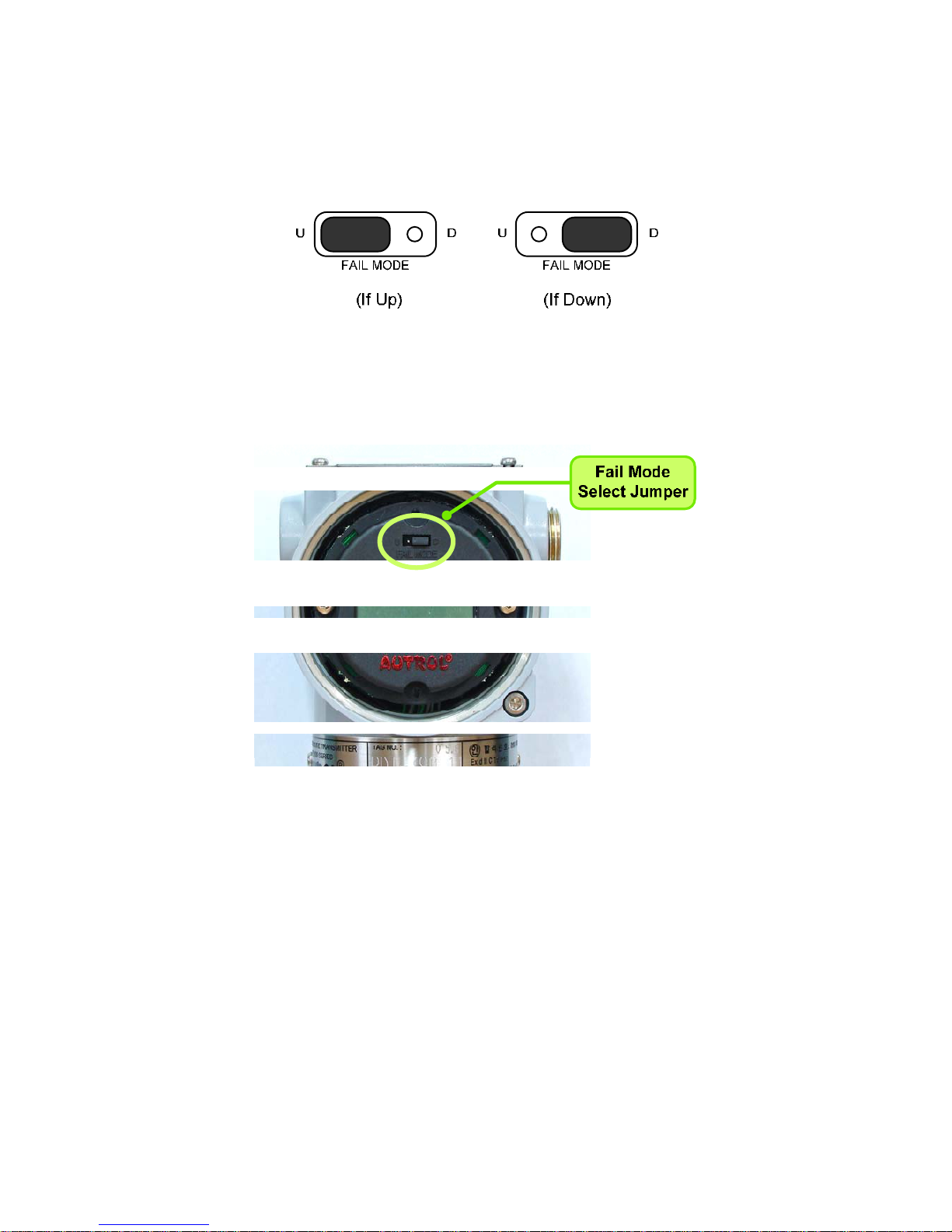
3-4. Fail Mode Alarm
AUTROL® Smart Pressure Transmitter automatically and continuously performs self-diagnostic
routines. If the self-diagnostic routines detect a failure, the transmitter drives its output outside of the
normal saturation values. The transmitter will drive its output low(down) or high(up) based on the
position of the failure mode alarm jumper . See Table 3.1 for Output values.
[Table 3-1 Standard Alarm and Saturation Value]
Fail Mode Select Jumper Switch has in LCD Module and Main CPU Module and Jumper Switch Line is
connected circuital. In case of Not LCD Module, we can use CPU Module's Fail Mode Select Jumper
Switch and In case of LCD Module we can use LCD Module's Jumper Switch. In this case, CPU Module
is selected "Down" side. No selected we can select "Down" side.
(Jumper Select Switch is followed in Figure 3-2, 3-3)
Select Fail Mode
Both LCD Module and CPU Module
Only CPU
Module
CPU Module LCD Module CPU Module
Fail Down Down D D
Fail Up
Down U
U
Up U or D
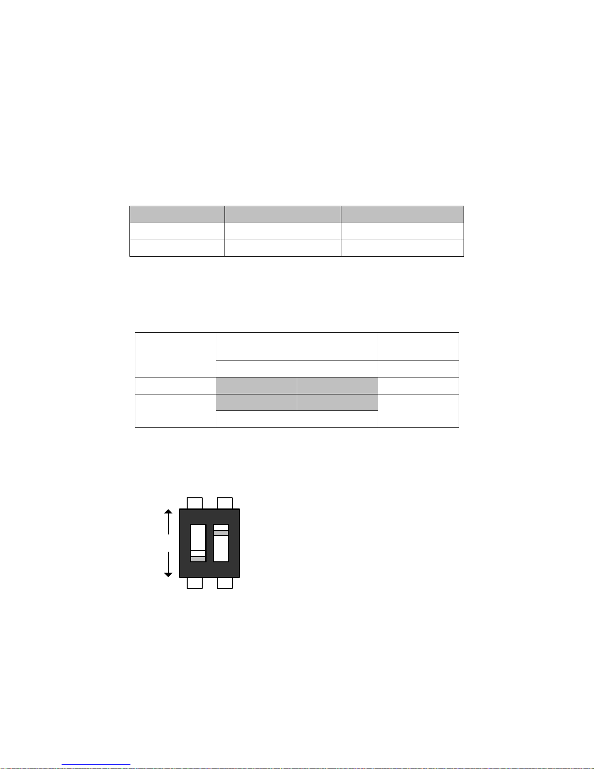
< Fail Mode Selection DIP Switch of CPU Module >
Level 4~20mA Saturation 4~20mA Alarm
Low/Down 3.9 mA
≤ 3.78 mA
High/Up 20.8 mA
≥ 21.1 mA
1
2
ON
Up
Down
1. WR_EN (EEPROM Write Enable)
DOWN : Enable
UP : Protected
2. Fail Mode Alarm
DOWN : Low
UP : High
APT3500 Smart Pressure Transmitter Operation Manual M3500-EO1G
17 DUON System Co., Ltd.
< Fail Mode Selection Jumper Switch of LCD Module >
Figure 3-1. Fail Mode and EEPROM-Write Selection Jumper Switch
Figure 3-2 Fail Mode Selection Jumper Switch of LCD Module
APT3500 Smart Pressure Transmitter Operation Manual M3500-EO1G
18 DUON System Co., Ltd.
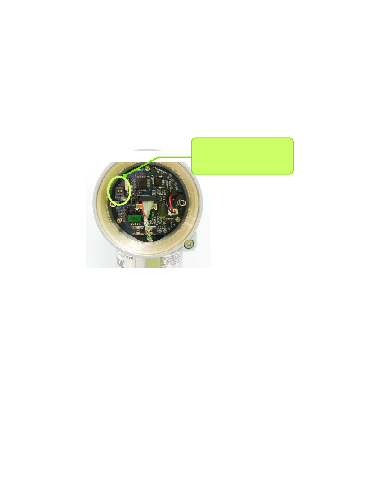
Figure 3-3. CPU Module Fail Mode, EEPROM-Write Selection Jumper Switch
3-5. EEProm-Write Enable / Disable Mode Switch
There is the EEPROM (Electrically Erasable Programmable ROM) restoring various configuration
variables in Transmitter. For protect to change configuration variable data in software, hardware side
there is Write-Protect Mode and Jumper Switch selected it segmented "EEP-Write DIS / EN " in Main
CPU Module. Thus if you connect Jumper to DIS you can't change configuration data in EEPROM,
when you connect Jumper to EN you can change configuration data in EEPROM. No connected Jumper,
it is classified EN. At the factory before shipment, it is configured "EN". (Following figure 3-3)
CPU Modue DIP Switch
1 : Fail Mode Selection
2 : EEPROM Write Selection
There are two security methods in APT3500. Following this.
(1) Security Jumper: protect to writing configuration parameters of transmitter.
(2) Physical removing Zero and Span Magnetic Buttons of Transmitter: you are not able to regulate
Zero and Span in Local.
[Notification] If EEP-Write is not connected, it is classified Security Off state.
3.5.1 Security Jumper (EEPROM Write Protect)
Protect to change Configuration Parameter of transmitter to Write Protect Jumper.
3.5.2 Zero and Span Magnetic Button
To remove Magnetic Button, you can't configure Zero and Span in Local.
.
APT3500 Smart Pressure Transmitter Operation Manual M3500-EO1G
19 DUON System Co., Ltd.
3.6 Configuration of Alarm and Security Jumper Procedures
To change Jumper's position, follow this.
(1) If install the transmitter, cutoff power.
(2) Open the housing front side covers. In case Power Supply, don't open the covers of
transmitter
(3) After turn off Jumper, turn on at wanted position.
(4) Close the housing covers. You must fully engage to meet explosion proof requirements
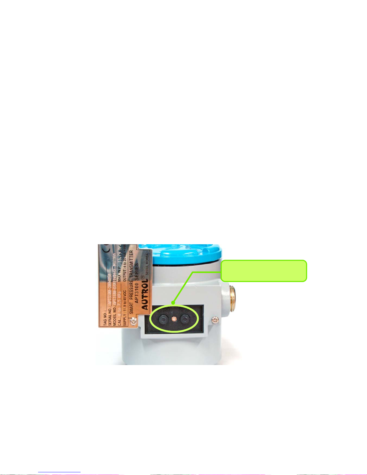
3.7 Configuration of Zero and Span Procedures
This product is designed to enable basic set-up only by Transmitter own buttons without additional
devices. Because progression of button manipulation is displayed on LCD, button manipulation can be
used only in products containing LCD module. Opening the Name Plate cover in the housing top, you
can see ZERO and SPAN buttons. This product uses contactless magnetic buttons, which are
completely separated from the Transmitter interior. Hence, this is suitable for the case, such as
flameproof environment, that Transmitter interior should be sealed.
ZERO & SPAN Button
[Note1] ZERO and SPAN button are designed to be active by finger push but, depending on use
environment, tools such as pen or screw driver should be used to push deep for accurate
action.
[Note2] If magnetic screw driver is used, button may not be active. Hence, non-magnetic screw
[Figure 3-4 Transmitter’s Zero/Span configuration Button]
 Loading...