

Duon System AUTROL Series, ATT2200, ATT2100 Operation Manual
ATT2100 / ATT2200 Smart Temperature Transmitter Operation Manual M2X00-E01H
* Information on this manual can be changed without an advance notice.
ATT2100/ATT2200
Smart Temperature Transmitter
Operation Manual
AUTROL Series Operation Manual : M2X00-E01H
Duon System Co., Ltd.
AUTROL
®
by DUON SYSTEM Co., Ltd
www.autrol.com

ATT2100 TEMPERATURE TRANSMITTER Operation Manual M2100-REV-G
1
ATT2100 Smart Temperature Transmitter
This manual is for general user to understand the installation and operatation of
ATT2100 / ATT2200 Smart Temperature Transmitter efficiently.
Before handling Autrol series device, all users have to be fully understand to control or get
some technical support.
Information on this manual can be changed without an advance notice.
DUON SYSTEM CO., Ltd
60-31, Gasan-dong, Guemchon-gu, Seoul, Korea
Tel: +82-2-860-7900
www.autrol.com
autrol@duon.co.kr

ATT2100 TEMPERATURE TRANSMITTER Operation Manual M2100-REV-G
2
Table of Contents
1. INTRODUCTION
1-1. USING THIS MANUAL
1-2. OVERVIEW OF TRANSMITTER
1-3. SOFTWARE COMPATIBILITY
1-4. TRANSMITTER COMPONENTS
2. HANDLING CAUTIONS
2-1. UNPACKING
2-2. MODEL AND SPECIFICATIONS CHECK
2-3. STORAGE
2-4. SELECTING THE INSTALLATION LOCATIONS
2-5. WATERPROOFING OF CABLE CONDUIT CONNECTIONS
2-6. RESTRICTIONS ON USE OF RADIO TRANSCEIVER
2-7. INSULATION RESISTANCE TEST AND DIELECTRIC STRENGTH TEST
2-8. INSTALLATION OF EXPLOSION PROTECTED TYPE TRANSMITTER
2.9 EMC CONFORMITY STANDARDS
3. TRANSMITTER FUNCTIONS
3-1. OVERVIEW
3-2. SAFETY MESSAGE
3-3. WARNING
3-4. WIRING

ATT2100 TEMPERATURE TRANSMITTER Operation Manual M2100-REV-G
3
3-5. FAIL MODE ALARM
3-6. EEPROM-WRITE ENABLE/DISABLE MODE JUMPER
3-7. CONFIGURATION OF ALARM AND SECURITY JUMPER PROCEDURE
3-8. CONFIGURATION OF ZERO AND SPAN PROCEDURE
3-9. CONFIGURATION OF ZERO POINT ADJUSTMENT PROCEDURE
3-10. COMMISSIONING ON THE BENCH WITH HHT
3-11. LCD MESSAGES
4. INSTALLATION
4-1. OVERVIEW
4-2. SAFETY MESSAGE
4-3. WARNING
4-4. COMMISSIONING ON THE BENCH WITH HAND-HELD TERMINAL
4-5. GENERAL CONSIDERATIONS
4-6. ELECTRICAL CONSIDERATIONS
4-7. POWER SUPPLY
4-8. WIRING
4-9. LOOP
4-10. WIRING INSTALLATION
4-11. GROUNDING
4-12. POWER SUPPLY VOLTAGE AND LOAD RESISTANCE
4-13. TEMPERATURE SENSOR INSTALLATION
4-14. MECHANICAL CONSIDERATIONS

ATT2100 TEMPERATURE TRANSMITTER Operation Manual M2100-REV-G
4
4-15. ENVIRONMENTAL CONSIDERATIONS
5. ON-LINE OPERATION
5-1. OVERVIEW
5-2. SAFETY MESSAG
5-3. CHECK OUTPUT
5-4. BASIC SETUP
5-5. DETAILED SETUP
5-6. INFORMATION VARIABLE SETUP
5-7. DIAGNOSITICS AND SERVICES
5-8. CALIBRATION
6. MAINTENANCE
6-1. OVERVIEW
6-2. SAFETY MESSAGE
6-3. HARDWARE DIAGNOSTICS
6-4. HARDWARE MAINTENANCE
APPENDIX I
ATT2100 SMART TEMPERATURE TRANSMITTER
LCD DISPLAY CODE

ATT2100 TEMPERATURE TRANSMITTER Operation Manual M2100-REV-G
5
Chapter 1 Introduction
The ATT2X00 Smart Temperature Transmitter is correctly calibrated at the factory before shipment. To
ensure correct and efficient use of the instrument, please read this manual thoroughly and fully
understand how to operate the instrument before operating it
① The contents of this manual are subject to change without prior notice.
② All rights reserved. No part of this manual may be reproduced in any form without DUON
System’s written permission.
③ If any question arises or errors are found, or if any information is missiong from this manual,
please inform the nearest DUON System sales office.
④ The specifications covered by this manual are limited to those for the standard type under the
specified model number break-down and do not cover custom-made instrument.
⑤ Please note that changes in the specifications, construction, or component parts of the
instrument may not immediatelty be reflected in this manual at the time of change, provided
that postponement of revisions will not cause difficulty to the user from a functional of
performance standpoint.
1-1 Using This Manual
The Chapters in this operating manual provide information on installing, operating, and maintaining
devices from the AUTROL Model ATT2100 Samrt Temperature Transmitter. The Chapters are organized as
follows.
Chapter 2 Handling Cautions
Chapter 2 provides instructon on unpacking, Storage and Selecting the installation locations.
Also, installation of explosion protected type transmitters at site and about EMC Conformity standards.
Chapter 3 Transmitter Functions
Chapter 3 contains in consideration of handling Model APT3100 Smart Pressure Transmitters.
Chapter 4 Installation
Chapter 4 contains mechanical, environment consideration and electrical installation instructions
on the Model ATT2100 Smart Temperature Transmitters.
Chapter 5 On-line Operation
Chapter 5 describes the configuration the parameter how to use variety of the Model ATT2100
Smart Temperature Transmitters' software fucntion and configuration.
Chapter 6 Maintenance
Chapter 6 contains hardware diagnostics, troubleshooting and maintenace task.

ATT2100 TEMPERATURE TRANSMITTER Operation Manual M2100-REV-G
6
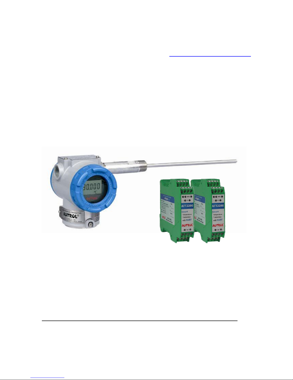
1.2 Overview of Transmitter
Autrol® Smart Temperature Transmitter based in a microprocessor is the temperature transmitter, has
temperature sensors such as Thermocouple, RTD, mV, Resistance for temperature measurement.
ATT2100 has a true draft analog range from 0 to 20mA offering that feature that a temperature range or
after convert analog range to HART (Communication) digital signal transmit for control systems like DCS,
PLC. This Model has explosion protected type and high precision, better reliabilty and is available on
digital commuication for the use remotes communication system.
This transmitter is enabled in HART commmunication with Host, HHT (HART Hand-Held Terminal) or PC
Configurator. Thus, transmitter various variables in host is enable to be changed, configured and tested
calibrated by users. For the HART Communication between DC Power Supply and Transmitter has to
terminate 250~ 600 Ohm.
1.3 Software Compatibility
Autrol® Smart Transmitter's software is implemented and complemented if necssary. Uses of the
transmitter will not be a compatibility software is contained in the host of the HHT(Model 275 HART
Communicator). In this case contact us for software DD(Device Descriptor) to be able to use with the
transmitter, you must to use loading in HHT, etc.
There may be some differences on supported fucntions as to Firmware Revision of transmiter. This
manual is based on Firmware Revision 58. Function deviations as to firmware Revision are same as
under box
FUNCTION
Function Supports
ZERO / SPAN Botton
Autrol PC/PDA HART 275/375
Before Rev. 58 Rev. 58
ZERO/SPAN
● ● ● ●
ZERO TRIM
● ● ● ●
ZERO Adj
● ● ● ●
Units set
ⅹ
● ● ●
Range set
ⅹ
● ● ●
Damping set
ⅹ
● ● ●
LCD Decimal set
ⅹ
● ● ∆
● : Supported.
ⅹ : Not Supported
∆ : Supported but update required
ATT2100 TEMPERATURE TRANSMITTER Operation Manual M2100-REV-G
7
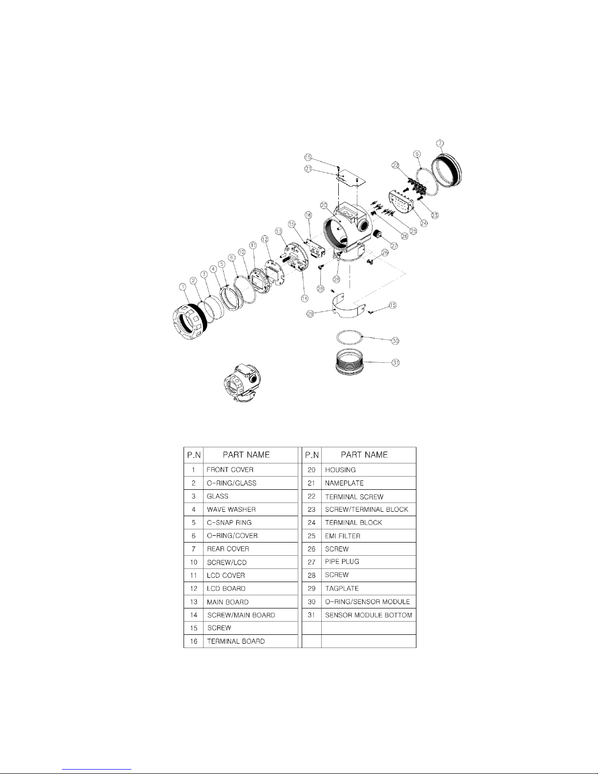
1.4 Transmitter Components
The components and figure of Autrol® Smart Temperature Transmitter ATT2100 is as follow.
Figure 1-1. Model ATT2100 Transmitter Expoded View (Housing)
Figure 1-2. TRANSMITTER COMPONENTS
ATT2100 TEMPERATURE TRANSMITTER Operation Manual M2100-REV-G
8
Chapter 2 Handling Cautions
This chapter consists of cautions for transmitter handling and storage, selection of installation locations,
insulation and explosion structure, etc.
[Quick Reference Manual]
Step Jog Job Details Instrument
1 Unpacking a) Unpack transmitter packing
2 Model and
Specifications
Check
a) Make sure whether the delivered transmitter is
same as options attached on its nameplate
3 Storage a) Places not exposed to water, non-vibration and
non-impact area
b) Ambient temperature 25 deg C and relative
humidity 65% RH
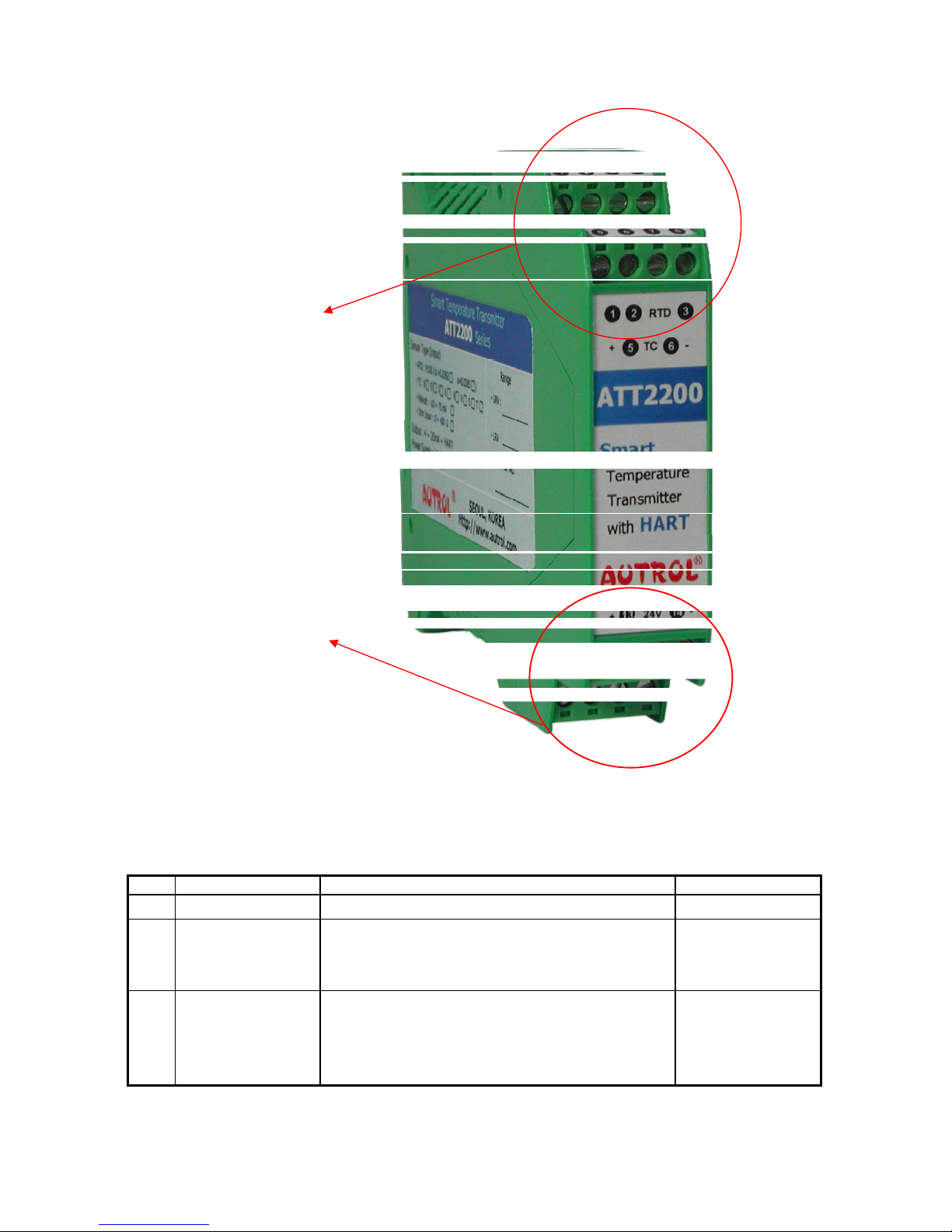
Sensor Element
connection terminal
Sensor Element
connection terminal

ATT2100 TEMPERATURE TRANSMITTER Operation Manual M2100-REV-G
9
4 Calibration on a
Calibration Room
a) Basic Configuration
b) Input RTD &TC, TC Cold Juction Calibration, DAC
Trim
HHT,
Galvanometer
5 InstallationLocation
a) Where ambient temperature is not fluctuated
b) Where corrosion happens by chemical materials,
etc.
c) Where vibration and impact is not severe
d) Where non-explosion area is matched on
explosionproof regulations
e) Where maintenance is very easy
(Engineering)
6 Mechanical
Considerations
a) Where transmitter can be handled easily (Engineering)
7 Electrical
Considerations
a) Connect 24 Vdc
(Power Supply is 11.9 Vdc – 45 Vdc)
b) For HART communication, total resistance on
transmitter terminal loop should be 250 – 550 Ohm.
(Engineering)
8 Mounting and
Installation
a) For mounting transmitter, an appropriate bracket
should be used.
b) Transmitter should be fixed well against swing.
(Mounting and
Installation)
9 Calibration on Spot a) Input mV value at 0 ℃, and compensation
(RTD: 100Ω, TC: according to sensor type 0 ℃
mV value)
b) Make sure that PV value of transmitter is zero
and current is 4 mA.
HHT,
Galvanometer
10 Opeation a) Make sure whether transmitter operates well or
not
Eye or HHT
2.1 Unpacking
When moving the transmitter to the installation site, keep it in its original packaging. Then, unpack the
transmitter there to avoid damage on the way.
2.2 Models and Specifications Check
The model name and specifications are indicated on the nameplate to the case. Please check your
specification and wanted model.
2.3 Storage
The following precautions must be observed when storing the instrument, especially for a long period.
(1) Select a storage area that meets the following conditions:

ATT2100 TEMPERATURE TRANSMITTER Operation Manual M2100-REV-G
10
(a) It is not exposed to rain or water.
(b) It suffers minimum vibration and shock.
(c) If possible, it is preferable at normal temperature and humidity (approx. 25°C, 65% RH).
However, it has an ambient temperature and relative humidity within the following ranges.
● Ambient Temperature: -40 ~ 85°C (without LCD module)
-30 ~ 80°C (with LCD module)
● Relative Humidity: 5% ~ 98% RH (at 40°C)
(2) When storing the transmitter, repack it as nearly as possible to the way it was packed when delivered
from the factory.
(3) Make sure before storing that the sensor module, flange, housing are securely mounted.
2.4 Selecting Installation Locations
The transmitter is designed to withstand severe environmental conditions. However, to ensure stable and
accurate operation for many years, the following precautions must be observed when selecting an
installation location.
(1) Ambient Temperature
Avoid locations subject to wide temperature variations or a significant temperature gradient. If the
location is exposed to radiant heat from plant equipment, provide adequate insulation or ventilation.
(2) Ambient Atmosphere
Avoid installing the transmitter in a corrosive atmosphere. If the transmitter must be installed in a
corrosive atmosphere, there must be adequate ventilation as well as measures to prevent intrusion
or stagnation of rainwater in conduits. Moreover, there should be appropriate ventilation preventing
corrosion by rain gathered on conduit.
(3) Shock and Vibration
Select an installation site suffering minimum shock and vibration (although the transmitter is
designed to be relatively resistant to shock and vibration)
(4) Installation of Explosion-protected Transmitters
Explosion-protected transmitters can be installed in hazardous areas according to the gas types for
which they are certified.
(5) Select a place that transmitter maintenance is very easy.
2.5 Waterproofing of Cable Conduit Connections
Apply a non-hardening sealant (silicone or tape, etc.) to the threads to waterproof the transmitter cable
conduit connections.
2.6 Restrictions on Use of Radio Transceivers
▲ Warning
◈ Although the transmitter has been designed to resist high frequency electrical noise, if a radio transeiver is
used near the transmitter of its external wiring, the transmitter may be affected by high frequency noise
pickup. To test for such effects, bring the transceiver in use slowly from a distance of several meters from
the transmitter, and observe the measurement loop for noise effects. Thereafter, always use the
transceiver outside the area affected by noise.

ATT2100 TEMPERATURE TRANSMITTER Operation Manual M2100-REV-G
11
2.7 Insulation Resistance Test and Dielectric Strength Test
Since the transmitter has undergone insulation resistance and dielectric strength tests at the factory
before shipment, normally these tests are not required. However, if required, observe the following
precautions in the test procedures.
(1) Do not perform such tests more frequently than is absolutely necessary. Even test voltages that
do not cause visible damage to the insulation may degrade the insulation and reduce safety margins.
(2) Never apply a voltage exceeding 500 Vdc (100 Vdc with an internal lightening protector) for the
insulation resistance test, nor a voltage exceeding 500V AC (100V AC with an internal lighting protector)
for the dielectric strength test.
(3) Before conducting these tests, disconnect all signal lines from the transmitter terminals. Perform
the tests in the following procedure.
(4) Insulation Resistance test
(a) Short-circuit the + and - SUPPLY terminals in the terminal box.
(b) Turn OFF the insulation tester. Then connect the insulation tester plus (+) lead wire to the
shorted SUPPLY terminals and the minus (-) lead wire to the grounding terminal.
(c) Turn ON the insulation tester power and measure the insulation resistance. The voltage should
be applied short as possible to verify that insulation resistance is at least 20MΩ.
(d) After completing the test and being very careful not to touch exposed conductors disconnect
the insulation tester and connect a 100kW resister between the grounding terminal and the shortcircuiting SUPPLY terminals. Leave this resistor connected at least three second to discharge any static
potential. Do not touch the terminal while it is discharging.
(5) Dielectric Strength Test
(a) Short-circuit the + and - SUPPLY terminals in the terminal box.
(b) Turn OFF the dielectric strength tester. Then connect the tester between th shorted SUPPLY
terminal and the grounding terminal. Be sure to connect the grounding lead of the dielectric strength
tester to the ground terminal.
(c) Set the current limit on the dielectric strength tester to 10mA, then turn ON the power and
gradually increase the tester voltage from '0' to the specified voltage.
(d) When the specified voltage is reached, hold it for one minute.
(e) After completing this test, slowly decrease the voltage to avoid any voltage surges.
2.8 Installation of Explosion Protected Type Transmitters
2.8.1 KOSHA Certification
Caution for KOSHA Flameproof is following type.
[Note1] Model ATT2100 diaphragm sealed for potentially explosive atmosphere:
Type of Protection and Marking Code: Ex d ⅡC T6
Temperature Class: T6
Ambient Temperature: -20 ~ 60'C
Process Temperature: Max. 80'C
[Note2] Electrical Data
Supply Voltage: Maximum 45 Vdc
Output signal: 4 ~ 20mA, maximum 22mA

ATT2100 TEMPERATURE TRANSMITTER Operation Manual M2100-REV-G
12
[Note3] Installation
All wiring shall comply with local installation requirement.
The cable entry devices shall be of a certified flameproof type, suitable for conditions of
use.
[Note4] Operation
Wait one minute after power -disconnection, before opening the enclosure.
Take care not to generate mechanical spark when access to the instrument and peripheral
devices in hazardous location.
[Note5] Maintenance and Repair
The instrument modification or parts replacement by other than authorized representative
of DUON System is prohibited and will void KOSHA Flameproof.
2.8.2 KEMA / ATEX Certification
ATEX Certification number : KEMA08ATEXxxxx
CE 0344
II 2 G
Note 1. Model ATT2100 for potentially explosive atmosphere
Ex d IIC T6... T4
Operating Temperature : -20℃≤ T
amb
+60C
T6 for process ≤ 85C;
T5 for process ≤ 100C;
T4 for process ≤ 130C;
Note 2. Electrical Data
Supply Voltage : 11.9 to 42 Vdc
Output Signal : 4 to 20 mA + HART
Note 3. Electrical Connection : 2 x 1/2-14NPT Female
Note 4. ATT2100 ATEX Certification is according to the below standards
EN 60079-0 : 2006
EN 60079-1 : 2007
Note 5. Installation
All wiring shall comply with local installation requirement.
The cable glands and blanking elements shall be of a certified flameproof type, suitable for
the condition of use and correctly installed. Also those devices should be endured at the
130C.
Housing Ground must be followed to “local electrical codes”. The most efficient ground
procedure is to connect directly to the earth as least impedance.
How to Housing Ground:
* Internal Ground Connection: Internal ground connection screw is located in terminal in
housing, the screw can be identified as ground sign.
* External Ground Assembly: This is located in the right side of housing and identified as
ground sign. (For grounding use a cable lug)
When use tubing, Stopping boxes must be connected with the wall of housing directly.
Tubing is installed a minimum of 5 threads.
Sensor is to be threaded a minimum of 7 threads and prevented from turning by tightening
the housing rotation set screw.
Do not disassemble flameproof Joints but in an unavoidable case to disassemble it or need
the specification of flameproof Joints, contact the manufacturer before doing.

ATT2100 TEMPERATURE TRANSMITTER Operation Manual M2100-REV-G
13
Note 6. Operation
WARNING-DO NOT OPEN WHEN AN EXPLOSIVE ATMOSPHERE MAY BE PRESENT
Take care not to generate mechanical spark when access to the instrument and peripheral
devices in hazardous location.
Note 7. Maintenance and Repair
The instrument modification or parts replacement by other than authorized representative
of DUON System is prohibited and will void KEMA/ATEX Explosion-proof / Flame-proof.
2-8-3. FM Certification
HAZARDOUS LOCATION ELECTRICAL EQUIPMENT
ATT2100-abcd. Temperature Transmitters.
XP/I/1/ABCD/T6 Ta = 60℃;
DIP/II, III/1/EFG/T6 Ta = 60℃;
a = Transmitter Type : S, D
b = Electrical Connection : 1
c = Hazardous Location Certification : F1.
d = Option : BA, BF, C7, M1, X
Equipment Rating :
Explosionproof for use in Class I, Division 1, Groups A, B, C and D;
Dust-Ignition proof for Class II, Division 1, Groups E, F and G;
Dust-ignition proof for Class II, Division 1
“T6, see instruction for temperature code if process temperature above 85℃”
Ambient Temperature : -20 to 60℃
Enclosure : indoors and outdoors, NEMA Type 4X
Conduit seal required within 18” for Group A only.
Nonincensive for Class I, Division 2, Groups A, B, C and D ; Class II, Division 2,
Groups E, F and G ; Class III, Division 1, Temperature Code T4
Ambient Temperature : -20 to 60℃
Enclosure : indoors and outdoors, NEMA Type 4X
2.9 EMC Conformity Standards
EMI (Emission): EN55011
EMS (Immunity): EN50082-2
DUON System recommends customer to apply the Metal Conduit Wiring or to upset he twisted pair
Shield Cable for signal wiring to conform the requirement of EMC Regulation, when customer installs
AUTROL Series Transmitters to the plant.
Chapter 3 Transmitter Functions
3.1 Overview
This Chapter contains information on operating Model ATT2100. Tasks that should be performed on the
bench priori to installation are explained in this chapter.

ATT2100 TEMPERATURE TRANSMITTER Operation Manual M2100-REV-G
14
3.2 Safety Message
Procedures and instructions in this chapter may require special precautions to ensure the safety of the
personal performing the operations. Information that raises potential safety issues is indicated by
warning symbol(▲). Refer to the following safety messages before performing an operation preceded by
this symbol.
3.3 Warning
▲ Warning
Explosion can result in death or serious injury:
◈ Do not remove the transmitter covers in explosion environments when the circuit is alive.
◈ Check transmitter to install accroding to Intrinsically safe regulation before HHT connect to Transmitter in
explosive environment.
◈ Transmitter covers must be fully engaged to meet explosionproof requirements.
▲ Warning
Electrical can result in death serious injury:
◈ The qualification which is educated only the person whom it prepares will be able to establish the
transmitter.
▲ Warning
Electrical can result in death serious injury:
◈ Avoid contact with the leads and terminals. High voltage that may be present on leads can cause electrical
shock.
ATT2100 TEMPERATURE TRANSMITTER Operation Manual M2100-REV-G
15
+ - - +
COMM TEST
1 2 3 4 5
POWER (+)
POWER (-)
RTD 2 wire
+ - - +
COMM TEST
1 2 3 4 5
POWER (+)
POWER (-)
RTD 3 wire
+ - - +
COMM TEST
1 2 3 4 5
POWER (+)
POWER (-)
RTD 4 wire
+ - - +
COMM TEST
TC(+)
TC(-)
1 2 3 4 5
POWER (+)
POWER (-)
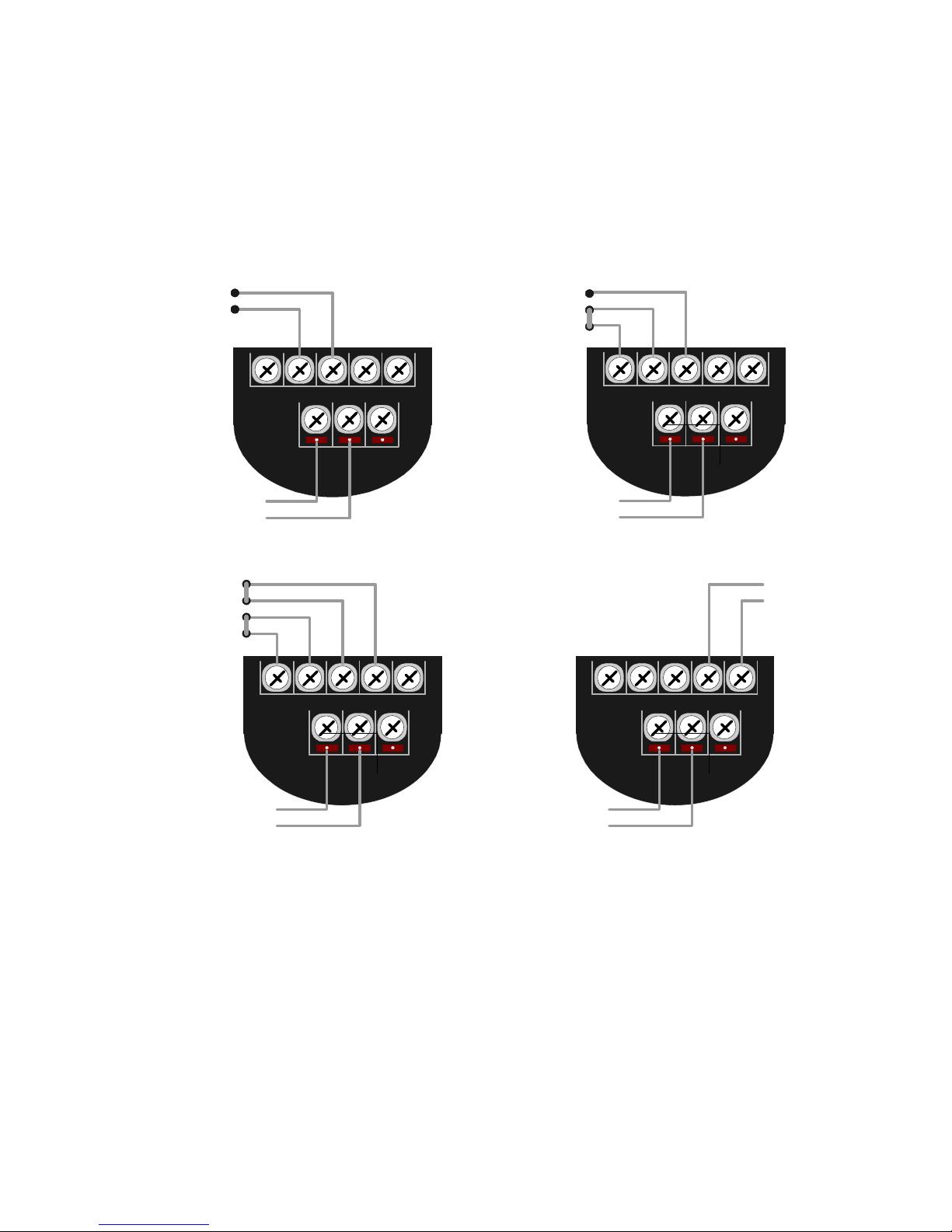
3.4 Connection of Sensor
ATT2100 Temperature Transmitter can input sensors such as RTD, Thermocouple(TC) and Resistance.
In case RTD, 2Wire/3Wire and 4Wire Sensor connection is applicable. Also, 2Wire TC(B, E, J, K, N, R, S,
T) Sensor input is applicable. Below pictures are present sensor connections using RTD & TC. Ex) In case
RTD 3Wire, common line connect to terminal No. 1, 2.
Figure 3-1. ATT2100 Temperature Transmitter Sensor Connections
 Loading...