

Page 1
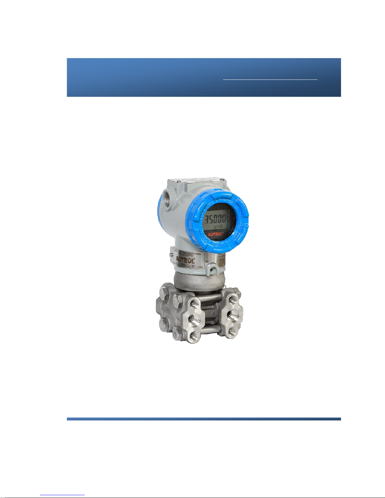
APT3500 Smart Pressure Transmitter Operation Manual M3500-E01A
* Information on this manual can be changed without an advance notice.
APT3500 Smart Pressure Transmitter
Operation Manual
DUON SYSTEM CO., LTD
Autrol
®
DUON SYSTEM Co., Ltd. http://www.autrol.com/
AUTROL Series Operation Manual : M3500-E01A
Page 2

APT3500 Smart Pressure Transmitter Operation Manual M3500-E01A
ii
Duon System Co.,Ltd.
Page 3

APT3500 Smart Pressure Transmitter Operation Manual M3500-E01A
APT3500 Smart Pressure Transmitter
This manual is made so that general user can help to install and operate
APT3500 Smart Pressure Transmitter efficiently.
Before handling APT3500 transmitter, all users have to be fully aware of it.
Information on this manual can be changed
Without an advance notice.
DUON SYSTEM CO., Ltd
60-31, Gasan-dong, Guemchon-gu, Seoul, Korea
Tel: +82-2-860-7900
Page 4

APT3500 Smart Pressure Transmitter Operation Manual M3500-EO1G
2 DUON System Co., Ltd.
Table of Contents
Chapter 1 Introduction
1.1 Using This Manual
1.2 Overview of Transmitter
1.3 Software Compatibility
1.4 Transmitter Components
Chapter 2 Handling Cautions
2.1 Unpacking
2.2 Models and Specifications Check
2.3 Storage
2.4 Selecting the Installation Locations
2.5 Calibration on Spot after Installation
2.6 Pressure Connections
2.7 Waterproofing of Cable Conduit Connections
2.8 Restrictions on Use of Radio Transceiver
2.9 Insulation Resistance Test and Dielectric Strength Test
2.10 Installation of Explosion Protected Type Transmitters
2.11 EMC Conformity Standards
Chapter 3 Transmitter Functions
3.1 Overview
3.2 Safety Messages
3.3 Warning
3.4 Fail Mode Alarm
3.5 EEProm-Write Enable and Disable Mode Switch
3.6 Configuration of Alarm and Security Jumper Procedures
3.7 Configuration of Zero and Span Procedures
3.8 Shop Commissioning using HHT
Chapter 4 Installation
4.1 Overview
4.2 Safety Messages
4.3 Warning
4.4 Commissioning on the bench with Hand-Held Terminal
4.5 General Considerations
4.6 Electrical Considerations (Power Supply)
4.7 Wiring
4.8 Mechanical Considerations
4.9 Environmental considerations
Page 5

APT3500 Smart Pressure Transmitter Operation Manual M3500-EO1G
3 DUON System Co., Ltd.
Chapter 5 On-line Operation
5.1 Overview
5.2 Safety Messages
5.3 Configuration Data Review
5.4 Check Output
5.5 Basic Setup
5.6 Detail Setup
5.7 Configuration of Information Variable
5.8 Configuration of Breakdown Diagnostics Function
5.9 Calibration
Chapter 6 Maintenance
6.1 Overview
6.2 Safety Messages
6.3 Hardware Diagnosis
6.4 Hardware Maintenance
Page 6

APT3500 Smart Pressure Transmitter Operation Manual M3500-EO1G
4 DUON System Co., Ltd.
Appendix I
APT3500 Smart Pressure Transmitter
LCD Display Code
APPENDIX II
PRODUCT CERTIFICATION
APPENDIX III
Special Condition for Safe use
Page 7

APT3500 Smart Pressure Transmitter Operation Manual M3500-EO1G
5 DUON System Co., Ltd.
Chapter 1 Introduction
The APT3500 Smart Pressure Transmitter are correctly calibrated at the factory before shipment. To
ensure correct and efficient use of the instrument, please read this manual thoroughly and fully
understand how to operate the instrument before operating it
① The contents of this manual are subject to change without prior notice.
② All rights reserved. No part of this manual may be reproduced in any form without DUON
System’s written permission.
③ If any question arises or errors are found, or if any information is missiong from this manual,
please inform the nearest DUON System sales office.
④ The specifications covered by this manual are limited to those for the standard type under the
specified model number break-down and do not cover custom-made instrument.
⑤ Please note that changes in the specifications, construction, or component parts of the
instrument may not immediatelty be reflected in this manual at the time of change, provided
that postponement of revisions will not cause difficulty to the user from a functional of
performance standpoint.
1-1 Using This Manual
The Chapters in this operating manual provide information on installing, operating, and maintaining
devices from the AUTROL Model APT3500 Samrt Pressure Transmitter. The Chapters are organized as
follows.
Chapter 2 Handling Cautions
Chapter 2 provides instructon on commissioning and operating Model APT3500 Smart
Pressure Transmitters. Informations on software functions, configuration parameters, and on-line
variables is also included.
Chapter 3 Transmitter Functions
Chapter 3 contains in consideration of handling Model APT3500 Smart Pressure Transmitters.
Chapter 4 Installation
Chapter 4 contains mechanical, environment consideration and electrical installation
instructions on the Model APT3500 Smart Pressure Transmitters.
Chapter 5 On-line Operation
Chapter 5 describes the configuration the parameter how to use variety of the Model
APT3500 Smart Pressure Transmitters' software fucntion and configuration. See the following list for
the details.
① Regulations of circuit's Input/Output characteristics; Sensor or Output Trim
② Changed of output characteristic; Range Configuration, Output Type, Damping,Unit
③ Changed of general data; Tag No.,Date,Message etc.
Chapter 6 Maintenance
Chapter 6 contains hardware diagnostics ,troubleshooting and maintenace task.
Page 8
APT3500 Smart Pressure Transmitter Operation Manual M3500-EO1G
6 DUON System Co., Ltd.
1.2 Overview of Transmitter
Autrol® Smart Pressure Transmitter based in a microprocessor is the pressure transmitter, has a
designed capacitance sensor optimized for draft measurement. APT3500 has a true draft analog range
from 4 to 20mA offering that feature that a pressure range or after convert analog range to HART
(Communication) digital signal transmit for control systems like DCS, PLC. This Model has explosion
protected type and high precision, better reliabilty and is available on digital commuication for the use
remotes communication system.
This transmitter is enabled in HART commmunication with Host, HHT (HART Hand-Held Terminal) or
PC Configurator. Thus, transmitter various variables in host is enable to be changed, configured and
tested calibrated by users. For the HART Communication between DC Power Supply and Transmitter
has to terminate 250~ 550 Ohm.
1.3 Software Compatibility
Autrol® Smart Pressure Transmitter's software is implemented and complemented if necssary. Uses of
the transmitter will not be a compatibility software is contained in the host of the HHT(ACONF312 or
275/375/475 HART Communicator). In this case contact us for software DD(Device Descriptor) to be
able to use with the transmitter, you must to use loading in HHT, etc.
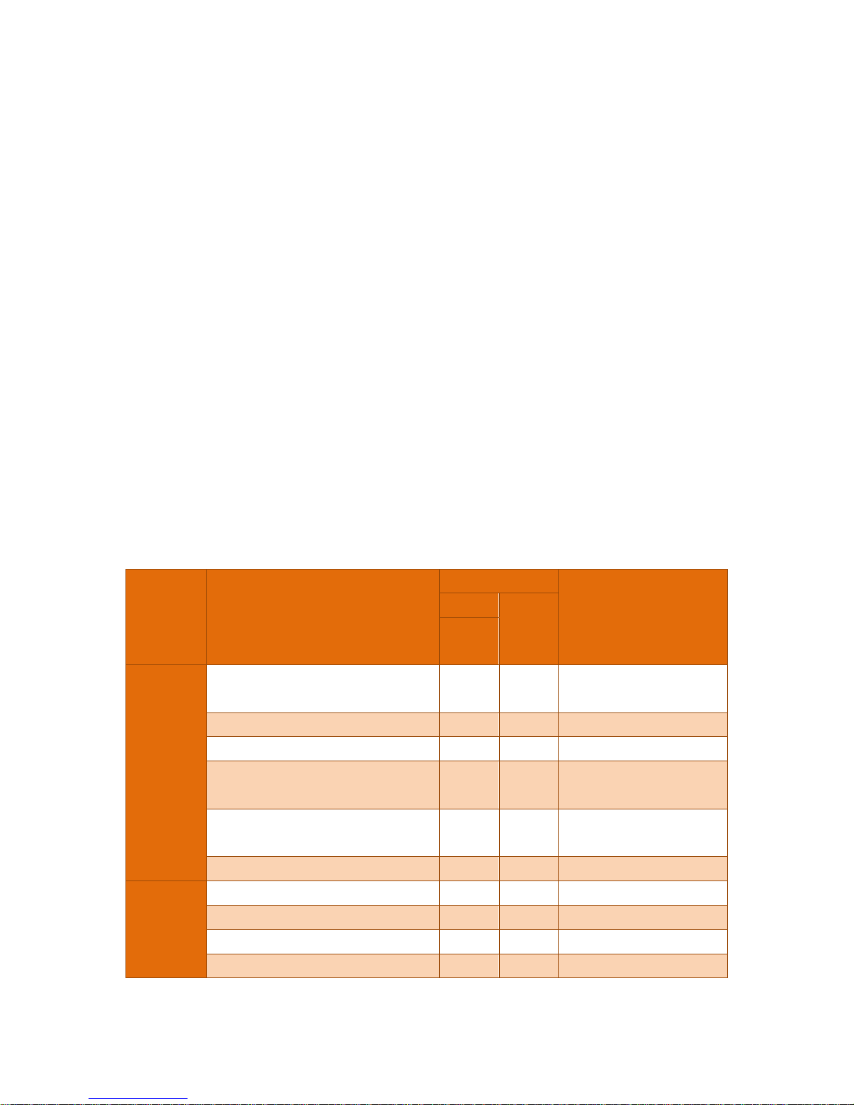
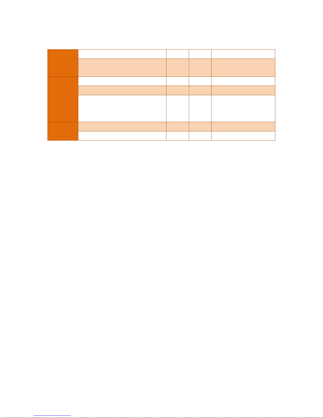
There may be some differences on supported fucntions as to Firmware Revision of transmiter. This
manual is based on Firmware Revision 10. Function deviations as to firmware Revision are same as
under box
Item Function
Function Supports
Output that is affected by
set-up change
Button HART
(HHT/
SST30)
Rev.10
Basic
Set-up
Range set ● ●
Whole output excluding PV
displayed on LCD
Units set ● ● PV displayed on LCD
Damping Seccond set ● ● Whole Output
Transfer Function set ● ●
Whole output excluding PV
displayed on LCD
Low-cut set ● ●
Whole output excluding PV
displayed on LCD
Loop Test ● ● 4~20mA
Calibration
Zero Trim ● ● Whole Output
Zero Adjustment ● ● Whole Output
Full Trim ⅹ ● Whole Output
D/A Trim ⅹ ● 4~20mA
Page 9
APT3500 Smart Pressure Transmitter Operation Manual M3500-EO1G
7 DUON System Co., Ltd.
Transm itter
Information
Set-up
Polling Address set ● ● 4~20mA
Setting up transmitter basic information
(Tag, Date, Descriptor, Message)
ⅹ ● -
LCD
Display
LCD mode set ● ● Whole LCD Display
Decimal Place set ● ● Whole LCD Display
LCD Engineering Mode set
(Eng Range, Eng Unit, Eng Transfer
Function…)
● ● LCD Engineering Value
Other
Button Lock set ● △ -
Master Reset ● ● Whole Output
: Supported.
ⅹ : Not Supported
: Supported but update required
Page 10
APT3500 Smart Pressure Transmitter Operation Manual M3500-EO1G
8 DUON System Co., Ltd.
1.4 Transmitter Components
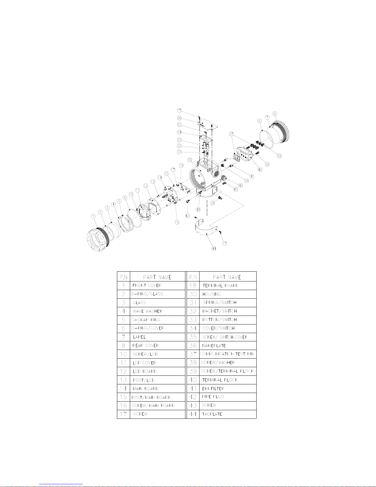
The components and figure of Autrol® Smart Pressure Transmitter is suggested on the next page.
Follow the precedure described on figure 1-1, 1-2, 1-3, 1-4, 1-5, 1-6.
Figure 1-1. Model APT3500 Transmitter Exposed View (Housing)
Figure 1-2. TRANSMITTER COMPONENTS
Page 11
APT3500 Smart Pressure Transmitter Operation Manual M3500-EO1G
9 DUON System Co., Ltd.
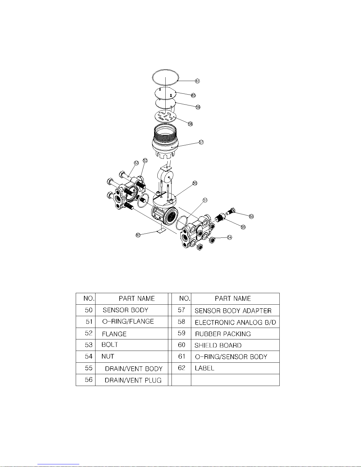
Figure 1-3. Model APT3500 Exploded View (Sensor Module-D,G,L)
Figure 1-4. TRANSMITTER COMPONENTS
Page 12

APT3500 Smart Pressure Transmitter Operation Manual M3500-EO1G
10 DUON System Co., Ltd.
Chapter 2 Handling Cautions
This chapter consists of cautions for transmitter handling and storage, selection of installation
locations, insulation and explosion structure, etc.
[Quick Reference Manual]
Step Job Job Details Instrument
1 Unpacking - Unpack transmitter packing
2
Model and
Specifications
Check
- Make sure whether the delivered transmitter is same
as options attached on its nameplate
3 Storage
- Places not exposed to water, non-vibration and non-
impact area
- Ambient temperature 25 deg C and relative humidity
65% RH
4
Calibration on a
Calibration Room
- Configuration of Range, Zero/Span, Unit, Tag,
Damping Time, Transfer Function, DA Trim and other
parameters
- HHT
- Pressure
Source
(requested)
- Galvanometer
5
Installation
Locations
- Where ambient temperature is not fluctuated
- Where corrosion happens by chemical materials, etc.
- Where vibration and impact is not severe
- Where non-explosion area is matched on
explosionproof regulations
- Where maintenance is very easy
(Engineering)
6
Mechanical
Considerations
- Where transmitter can be handled easily
- Be cautious not leaking the pressure.
(Engineering)
7
Electrical
Considerations
- Connect 24 Vdc
(Power Supply is 12 Vdc – 45 Vdc)
- For HART communication, total resistance on
transmitter terminal loop should be 250 – 550 Ohm.
(Engineering)
8
Mounting and
Installation
- For mounting transmitter, an appropriate bracket
should be used.
- Transmitter should be fixed well against swing.
(Mounting and
Installation)
9
Calibration on
Spot
- Sensor Zero Trim has to be done after ten seconds,
namely, differential pressure become zero and
stabilized.
- Make sure that PV value of transmitter is zero and
current is 4 mA.
HHT or
Zero/Span
button
10 Pressure
- Do not apply the regulated differential and line
pressure.
- Close equalizing valve of 3 valve manifold, Then,
open stop valve on high and low side slowly and
simultaneously.
(Applying
pressure)
11 Operation - Make sure whether transmitter operates well or not Eye or HHT
Page 13

APT3500 Smart Pressure Transmitter Operation Manual M3500-EO1G
11 DUON System Co., Ltd.
2.1 Unpacking
When moving the transmitter to the installation site, keep it in its original packaging. Then, unpack
the transmitter there to avoid damage on the way.
2.2 Models and Specifications Check
The model name and specifications are indicated on the nameplate to the case. Please check your
specification and wanted model.
2.3 Storage
The following precautions must be observed when storing the instrument, especially for a long period.
(1) Select a storage area that meets the following conditions:
(a) It is not exposed to rain or water.
(b) It suffers minimum vibration and shock.
(c) If possible, it is preferable at normal temperature and humidity (approx. 25°C, 65% RH).
However, it has an ambient temperature and relative humidity within the following ranges.
● Ambient Temperature: -40 ~ 85°C (without LCD module)
-30 ~ 80°C (with LCD module)
* General Use -20 ~ 60°C (CSA Explosionproof)
● Relative Humidity: 5% ~ 98% RH (at 40°C)
(2) When storing the transmitter, repack it as nearly as possible to the way it was packed when
delivered from the factory.
(3) If storing a transmitter that has been used, thoroughly clean diaphragm surfaces (the pressure-
detector sections) of the diaphragm seals, so that no measured fluid remains on them. In addition,
make sure before storing that the pressure-detector and transmitter assemblies are securely
mounted.
2.4 Selecting the Installation Locations
The transmitter is designed to withstand severe environmental conditions. However, to ensure stable
and accurate operation for many years, the following precautions must be observed when selecting an
installation location.
(1) Ambient Temperature
Avoid locations subject to wide temperature variations or a significant temperature gradient. If the
location is exposed to radiant heat from plant equipment, provide adequate insulation or
ventilation.
(2) Ambient Atmosphere
Avoid installing the transmitter in a corrosive atmosphere. If the transmitter must be installed in a
corrosive atmosphere, there must be adequate ventilation as well as measures to prevent intrusion
or stagnation of rainwater in conduits. Moreover, there should be appropriate ventilation
preventing corrosion by rain gathered on conduit.
(3) Shock and Vibration
Select an installation site suffering minimum shock and vibration (although the transmitter is
designed to be relatively resistant to shock and vibration)
(4) Installation of Explosion-protected Transmitters
Explosion-protected transmitters can be installed in hazardous areas according to the gas types
for which they are certified.
Page 14

APT3500 Smart Pressure Transmitter Operation Manual M3500-EO1G
12 DUON System Co., Ltd.
(5) Select a place that transmitter maintenance is very easy.
2.5 Calibration on Spot after Installation
(1) Sensor Zero Trim should be done after transmitter is installed on spot, because zero point is not
accurate as to mounting status.
(2) For Sensor Zero Trim, make differential pressure of transmitter for zero in advance. Then, make
Sensor Zero Trim after pressure is sufficiently stabilized (after approximately 10 seconds).
(3) There are two ways for making differential pressure for zero. One is to apply zero differential
pressure (making same pressure both high and low side pressure). The other is to close Hign and
Low side of stop valve of 3 valve manifold and to open its equalizing valve.
(4) Sensor Zero Trimming is to use HHT (ACONF312 or 275/375/475 HART Communicator), PC or PDA
configurator, and to use Zero/Span button. Make sure all details on this manual.
(5) Refer to On-line Operation for configuring another parameters except Sensor Zero Trim
2.6 Pressure Connections
The following precautions must be observed in order to safely operate the transmitter under pressure.
(1) Never apply a pressure higher than the specified maximum working pressure.
(2) Confirm the option of pressure connection of transmitter. Necessarily use standardized and quality-
approved parts.
(3) In case of being needed by hard circumstances and regulations, there should be seal equipment
for leakage.
2.7 Waterproofing of Cable Conduit Connections
Apply a non-hardening sealant (silicone or tape, etc.) to the threads to waterproof the transmitter
cable conduit connections.
2.8 Restrictions on Use of Radio Transceivers
▲ Warning
◈ Instrument installed in the process is under presure. Never loosen or tighten the flange bolts as it may
cause dangerous spouting of process fluid.
◈ If the accumulated process fluid may be toxic or otherwise harmful, take approriate care to avoid contack
with the body of inhalation of vapors even after dismounting the instrument from process line for
maintenance.
Page 15

APT3500 Smart Pressure Transmitter Operation Manual M3500-EO1G
13 DUON System Co., Ltd.
2.9 Insulation Resistance Test and Dielectric Strength Test
Since the transmitter has undergone insulation resistance and dielectric strength tests at the factory
before shipment, normally these tests are not required. However, if required, observe the following
precautions in the test procedures.
(1) Do not perform such tests more frequently than is absolutely necessary. Even test voltages that
do not cause visible damage to the insulation may degrade the insulation and reduce safety margins.
(2) Never apply a voltage exceeding 500 Vdc (100 Vdc with an internal lightening protector) for
the insulation resistance test, nor a voltage exceeding 500V AC (100V AC with an internal lighting
protector) for the dielectric strength test.
(3) Before conducting these tests, disconnect all signal lines from the transmitter terminals.
Perform the tests in the following procedure.
(4) Insulation Resistance test
(a) Short-circuit the + and - SUPPLY terminals in the terminal box.
(b) Turn OFF the insulation tester. Then connect the insulation tester plus (+) lead wire to the
shorted SUPPLY terminals and the minus (-) lead wire to the grounding terminal.
(c) Turn ON the insulation tester power and measure the insulation resistance. The voltage
should be applied short as possible to verify that insulation resistance is at least 20M.
(d) After completing the test and being very careful not to touch exposed conductors disconnect
the insulation tester and connect a 100k resister between the grounding terminal and the short-
circuiting SUPPLY terminals. Leave this resistor connected at least three second to discharge any static
potential. Do not touch the terminal while it is discharging.
(5) Dielectric Strength Test
(a) Short-circuit the + and - SUPPLY terminals in the terminal box.
(b) Turn OFF the dielectric strength tester. Then connect the tester between the shorted SUPPLY
terminal and the grounding terminal. Be sure to connect the grounding lead of the dielectric strength
tester to the ground terminal.
▲ Warning
◈ Although the transmitter has been designed to resist high frequency electrical noise, if a radio transeiver is
used near the transmitter of its external wiring, the transmitter may be affected by high frequency noise
pickup. To test for such effects, bring the transceiver in use slowly from a distance of several meters from
the transmitter, and observe the measurement loop for noise effects. Thereafter, always use the
transceiver outside the area affected by noise.
Page 16

APT3500 Smart Pressure Transmitter Operation Manual M3500-EO1G
14 DUON System Co., Ltd.
(c) Set the current limit on the dielectric strength tester to 10mA, then turn ON the power and
gradually increase the tester voltage from '0' to the specified voltage.
(d) When the specified voltage is reached, hold it for one minute.
(e) After completing this test, slowly decrease the voltage to avoid any voltage surges.
2.10 Installation of Explosion Protected Type Tra ns mi tters
2.10.1 KOSHA Certification
Caution for KOSHA Flameproof is following type.
[Note1] Model APT3500 diaphragm sealed for potentially explosive atmosphere:
Type of Protection and Marking Code: Ex d ⅡC T6
Temperature Class: T6
Ambient Temperature: -20 ~ 60'C
Process Temperature: Max. 80'C
[Note2] Electrical Data
Supply Voltage: Maximum 45 Vdc
Output signal: 4 ~ 20mA, maximum 22mA
[Note3] Installation
All wiring shall comply with local installation requirement.
The cable entry devices shall be of a certified flameproof type, suitable for conditions of
use.
[Note4] Operation
Wait one minute after power -disconnection, before opening the enclosure.
Take care not to generate mechanical spark when access to the instrument and
peripheral devices in hazardous location.
[Note5] Maintenance and Repair
The instrument modification or parts replacement by other than authorized
representative of DUON System is prohibited and will void KOSHA Flameproof.
2.11 EMC Conformity Standards
EMC Standaed : IEC 61000-4 series
DUON System recommends customer to apply the Metal Conduit Wiring or to upset he twisted pair
Shield Cable for signal wiring to conform the requirement of EMC Regulation, when customer installs
AUTROL Series Transmitters to the plant.
Page 17

APT3500 Smart Pressure Transmitter Operation Manual M3500-EO1G
15 DUON System Co., Ltd.
Chapter 3 Transmitter Functions
3.1 Overview
This Chapter contains information on operating Model APT3500. Tasks that should be performed on
the bench priori to installation are explained in this chapter.
3.2 Safety Message
Procedures and instructions in this chapter may require special precautions to ensure the safety of the
personal performing the operations. Information that raises potential safety issues is indicated by
warning symbol(▲). Refer to the following safety messages before performing an operation preceded
by this symbol.
3.3 Warning
▲ Warning
Explosion can result in death or serious injury:
◈ Do not remove the transmitter covers in explosion environments when the circuit is alive.
◈ Transmitter covers must be fully engaged to meet explosionproof requirements.
▲ Warning
Electrical can result in death serious injury:
◈ The qualif ication which is educated only the person whom it prepares will be able to establish the
transmitter.
▲ Warning
Electrical can result in death serious injury:
◈ Avoid contact with the leads and terminals. High voltage that may be present on leads can cause electrical
shock.
Page 18
APT3500 Smart Pressure Transmitter Operation Manual M3500-EO1G
16 DUON System Co., Ltd.
3-4. Fail Mode Alarm
AUTROL® Smart Pressure Transmitter automatically and continuously performs self-diagnostic
routines. If the self-diagnostic routines detect a failure, the transmitter drives its output outside of the
normal saturation values. The transmitter will drive its output low(down) or high(up) based on the
position of the failure mode alarm jumper . See Table 3.1 for Output values.
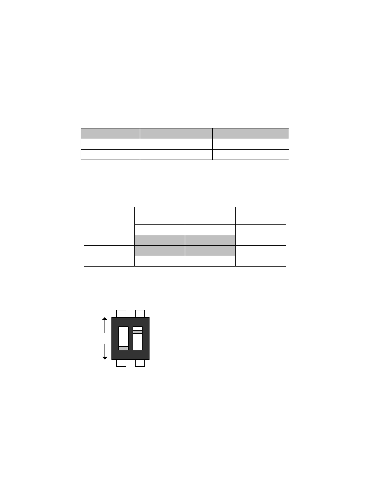
[Table 3-1 Standard Alarm and Saturation Value]
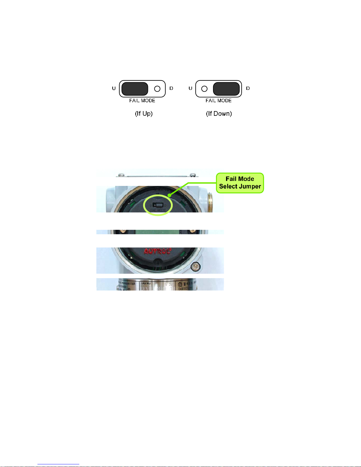
Fail Mode Select Jumper Switch has in LCD Module and Main CPU Module and Jumper Switch Line is
connected circuital. In case of Not LCD Module, we can use CPU Module's Fail Mode Select Jumper
Switch and In case of LCD Module we can use LCD Module's Jumper Switch. In this case, CPU Module
is selected "Down" side. No selected we can select "Down" side.
(Jumper Select Switch is followed in Figure 3-2, 3-3)
Select Fail Mode
Both LCD Module and CPU Module
Only CPU
Module
CPU Module LCD Module CPU Module
Fail Down Down D D
Fail Up
Down U
U
Up U or D
< Fail Mode Selection DIP Switch of CPU Module >
Level 4~20mA Saturation 4~20mA Alarm
Low/Down 3.9 mA
≤ 3.78 mA
High/Up 20.8 mA
≥ 21.1 mA
1
2
ON
Up
Down
1. WR_EN (EEPROM Write Enable)
DOWN : Enable
UP : Protected
2. Fail Mode Alarm
DOWN : Low
UP : High
Page 19
APT3500 Smart Pressure Transmitter Operation Manual M3500-EO1G
17 DUON System Co., Ltd.
< Fail Mode Selection Jumper Switch of LCD Module >
Figure 3-1. Fail Mode and EEPROM-Write Selection Jumper Switch
Figure 3-2 Fail Mode Selection Jumper Switch of LCD Module
Page 20
APT3500 Smart Pressure Transmitter Operation Manual M3500-EO1G
18 DUON System Co., Ltd.
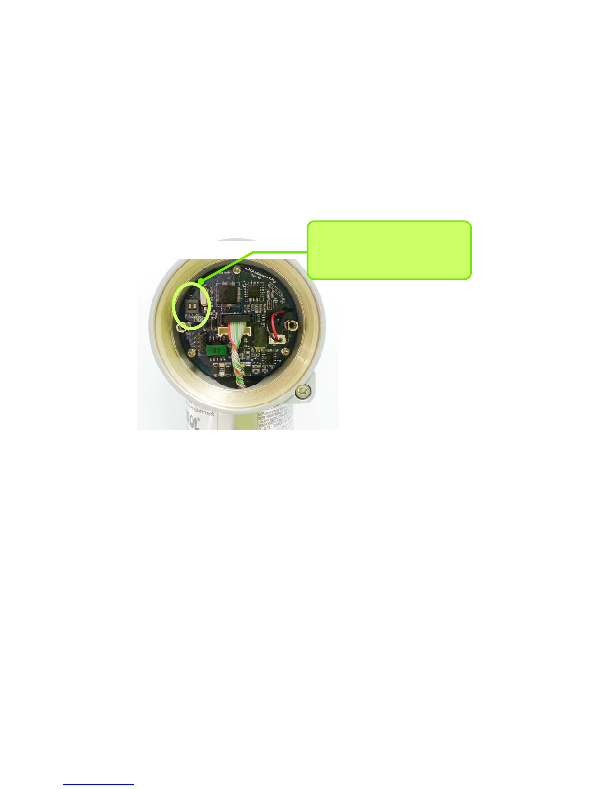
Figure 3-3. CPU Module Fail Mode, EEPROM-Write Selection Jumper Switch
3-5. EEProm-Write Enable / Disable Mode Switch
There is the EEPROM (Electrically Erasable Programmable ROM) restoring various configuration
variables in Transmitter. For protect to change configuration variable data in software, hardware side
there is Write-Protect Mode and Jumper Switch selected it segmented "EEP-Write DIS / EN " in Main
CPU Module. Thus if you connect Jumper to DIS you can't change configuration data in EEPROM,
when you connect Jumper to EN you can change configuration data in EEPROM. No connected Jumper,
it is classified EN. At the factory before shipment, it is configured "EN". (Following figure 3-3)
CPU Modue DIP Switch
1 : Fail Mode Selection
2 : EEPROM Write Selection
There are two security methods in APT3500. Following this.
(1) Security Jumper: protect to writing configuration parameters of transmitter.
(2) Physical removing Zero and Span Magnetic Buttons of Transmitter: you are not able to regulate
Zero and Span in Local.
[Notification] If EEP-Write is not connected, it is classified Security Off state.
3.5.1 Security Jumper (EEPROM Write Protect)
Protect to change Configuration Parameter of transmitter to Write Protect Jumper.
3.5.2 Zero and Span Magnetic Button
To remove Magnetic Button, you can't configure Zero and Span in Local.
.
Page 21
APT3500 Smart Pressure Transmitter Operation Manual M3500-EO1G
19 DUON System Co., Ltd.
3.6 Configuration of Alarm and Security Jumper Procedures
To change Jumper's position, follow this.
(1) If install the transmitter, cutoff power.
(2) Open the housing front side covers. In case Power Supply, don't open the covers of
transmitter
(3) After turn off Jumper, turn on at wanted position.
(4) Close the housing covers. You must fully engage to meet explosion proof requirements
3.7 Configuration of Zero and Span Procedures
This product is designed to enable basic set-up only by Transmitter own buttons without additional
devices. Because progression of button manipulation is displayed on LCD, button manipulation can be
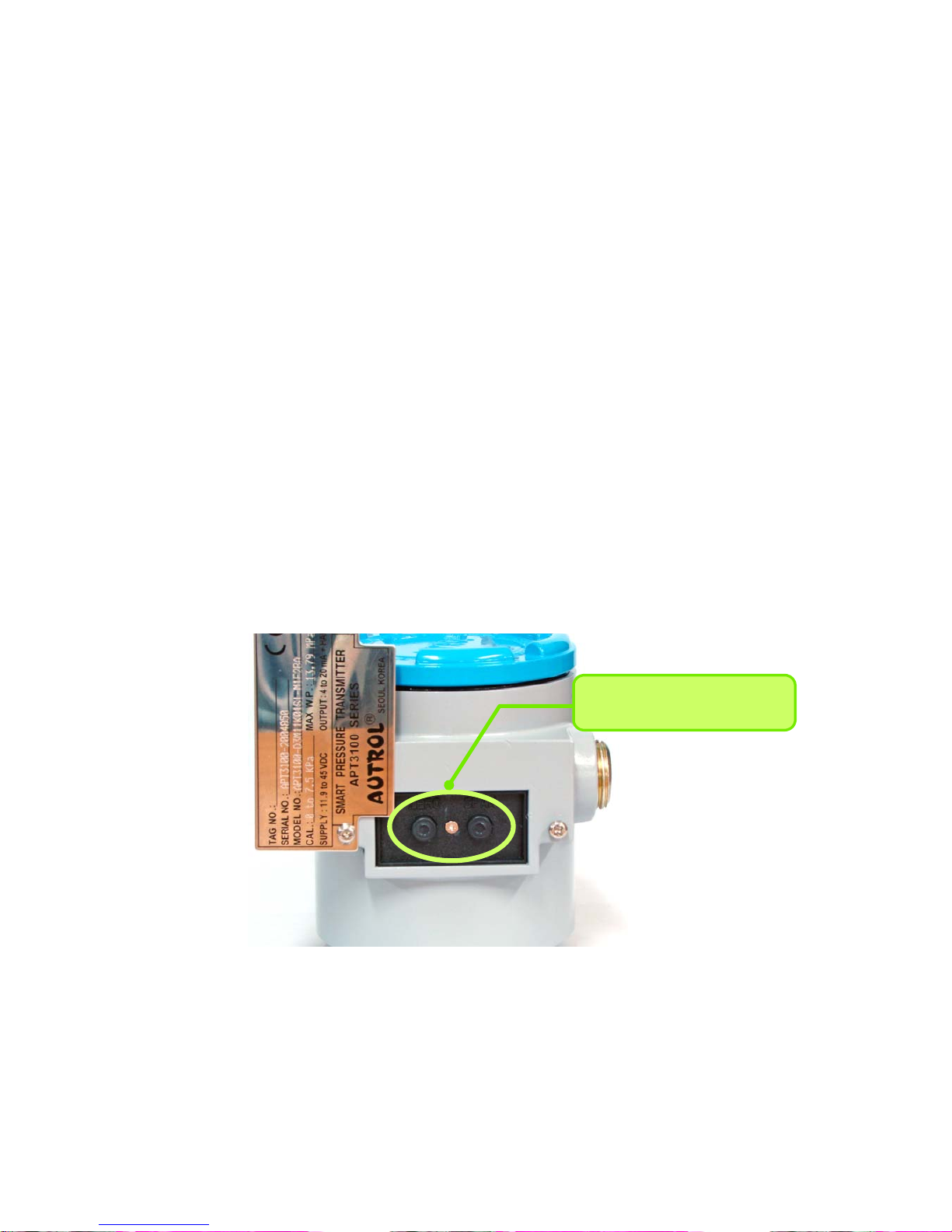
used only in products containing LCD module. Opening the Name Plate cover in the housing top, you
can see ZERO and SPAN buttons. This product uses contactless magnetic buttons, which are
completely separated from the Transmitter interior. Hence, this is suitable for the case, such as
flameproof environment, that Transmitter interior should be sealed.
ZERO & SPAN Button
[Note1] ZERO and SPAN button are designed to be active by finger push but, depending on use
environment, tools such as pen or screw driver should be used to push deep for accurate
action.
[Note2] If magnetic screw driver is used, button may not be active. Hence, non-magnetic screw
[Figure 3-4 Transmitter’s Zero/Span configuration Button]
Page 22

APT3500 Smart Pressure Transmitter Operation Manual M3500-EO1G
20 DUON System Co., Ltd.
driver should definitely be used.
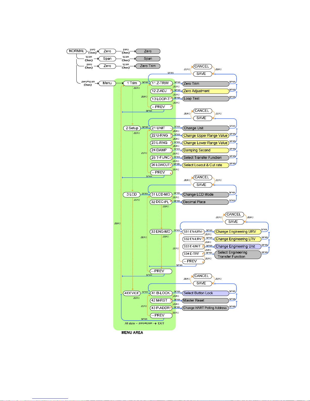
To provide various set-up functions with 2 buttons, ZERO and SPAN, this product allows menu control
in the Tree method.
Using functions which supported by buttons,
(1) Zero/Span Button mounted in Transmitter.
(2) HHT Configurator by HART Communication (following chapter 4)
** Refer to “275 Hart Communicator User Guide” on Appendix II for details.
Zero/Span configuration process by Zero/Span Button of transmitter is following this.
(1) Release to both sides bolts of Name Plate in the upper part of transmitter and if push down right
of Name Plate, appear to Zero/Span Button (following figure 3-4)
(2) Zero Configurations
Set the current process value for Lower Range Value (4 mA).
Put purposed pressure for zero over 10 seconds and push Zero Button over 5 seconds. Then show
“Zero” in LCD window. After checking this message, take off the finger from the button. Push the
button over 3 seconds after 1 second passes. Then show “-ZE-“ in LCD window. By this message, all
zero configurations have finished. If the works has failed, show “SPEr” or “SEtE” in LCD window.
(3) Span Configurations
Set the current process value for Upperr Range Value (20 mA).
Put purposed pressure for zero over 10 seconds and push Span Button over 5 seconds. Then show
“SPAn” in LCD window. After checking this message, take off the finger from the button. Push the
button over 3 seconds after 1 second passes. Then show “-SP-“ in LCD window. By this message, all
zero configurations have finished. If the works has failed, show “SPEr” or “SEtE” in LCD window.
Please refer to Appendix 1 for the button error and LCD display message
The other functions which supported by ZERO / SPAN Buttons are available as below.
Page 23
APT3500 Smart Pressure Transmitter Operation Manual M3500-EO1G
21 DUON System Co., Ltd.
[Menu Tree of ZERO+SPAN Button Function]
Page 24

APT3500 Smart Pressure Transmitter Operation Manual M3500-EO1G
22 DUON System Co., Ltd.
(1) Moving within menu: Zero
(2) Enter or moving to sub menu: Span
(3) Button manipulation ending or DIGIT movement: ZERO + SPAN (simultaneous push of ZERO and
SPAN)
(4) Button input time: - 3 seconds in Normal mode
- Instant after entering menu
In the normal operation mode, if you push ZERO+SPAN button for 3 seconds, LCD displays
"Menu" and, if you release button, LCD displays the initial item “1 Trim" and you enter the
menu Tree.
After that, button may be pushed shortly for input. In the menu Tree, you can push ZERO
button to move to the next item and push SPAN button to execute the indicated item or to
move to low level menu. If you choose “-- PREV” out of the menu items and push SPAN
button, you go to high level menu.
After entering the menu Tree, if the currently chosen item is within the MENU AREA in the
above Figure, ZERO+SPAN input terminates button manioulation and returns you to the normal
mode. In the menu Tree, if ZERO and SPAN button is pushed long the pushed button is input
repeatedly.
After completing choice and input of each function, choose “SAVE” and “CANCEL” to confirm
the result of application. “SAVE” and “CANCEL” are converted each time ZERO button is pushed,
and if you choose “SAVE” and, then, push SPAN input is applied, and if you choose “CANCEL”
and, then, push SPAN the present input is cancelled.
Caution: After about 30 seconds without any action, the button function will be finished.
How to input numerical value
Function needs to put numerical value: Functions of 12 Zero Adjustment, 22 Change
Upper Range Value, 23 Change Lower Range Value, 24 Damping Second require
numerical input.
Numerical input method: Once numerical input starts, the highest input DIGIT flickers. Then, if
you push ZERO number increases while if you push SPAN number decreases. If you push
ZERO+SPAN after changing to the desired number, the next DIGIT flickers and you can use
Page 25
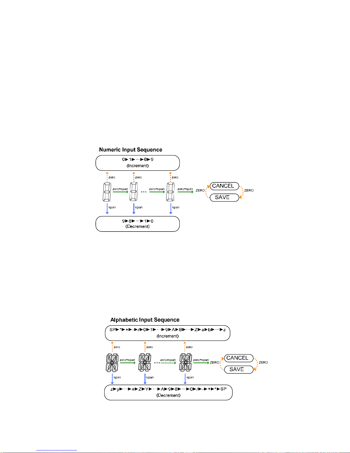
APT3500 Smart Pressure Transmitter Operation Manual M3500-EO1G
23 DUON System Co., Ltd.
ZERO and SPAN button to change vaue in the same method.
After repeating the above procedure and changing value to the last DIGIT, push ZERO+SPAN to
complete numerical input, and make the final check of the entered value. While LCD displays
“SAVE”, push SPAN button to apply the entered value and complete numerical input procedure.
If you push ZERO button while LCD displays “SAVE”, “CANCEL” is displayed. Then, if you push
SPAN button the entered value is cancelled.
How to input character value
Function needs to put character value: Functions of 333 Change Engineering Unit, 41
Select Button Lock require latter input.
Letter input method is the same as numerical input method except that not only number but
also letter and partly special character can be enter into each DIGIT.
Page 26

APT3500 Smart Pressure Transmitter Operation Manual M3500-EO1G
24 DUON System Co., Ltd.
Exercises for each function
- ZERO TRIM
- Executing the menu to put ZERO+SPAN button.
- Moving to the sub directory to put Span button when 1 TRIM message appear.
- Executing Zero Trim Function to put the Span button when 11 Z-TRIM message appear.
- If “SAVE” is displayed, push SPAN Button to save set-up value.
- Zero Adjustment : To change the PV value as 14
- Executing the menu to put ZERO+SPAN button.
- Moving to the sub directory to put Span button when 1 TRIM message appear.
- Moving to next menu to put Zero button when 11 Z-TRIM message appear.
- Executing Zero Adjustment function to put Span button when 12 Z-ADJ message appear.
- LCD displays ‘0.0’ and the highest input DIGIT flickers.
- If the flickering DIGIT is not tens place, push ZERO+SPAN button until tens place flickers.
- When tens place flickers, push ZERO button once to change the LCD display value to "10.0".
Then, push ZERO+SPAN button.
- When units place flickers, push ZERO button 4 times to change the LCD display value to
"14.0". Then, until “SAVE" is displayed, push ZERO+SPAN button repeatedly.
- If “SAVE” is displayed, push SPAN Button to save set-up value.
- Loop Test : Fix the 4~20mA Loop Current output to a certain value.
- Executing the menu to put ZERO+SPAN button.
- Moving to the sub directory to put Span button when 1 TRIM message appear.
- Moving to next menu to put Zero button when 11 Z-TRIM message appear.
- Moving to next menu to put Zero button when 12 Z-ADJ message appear.
- Executing Loop Test function to put Span button when 13 LOOP-T message appear.
- If Loop Test Function is performed, usable modes are indicated in the 2nd line of LCD, and
indication contents are as follows:
Indication
Content
Explanation
OFF The current that corresponds to PV measured without using
Loop Test function is sent out
Page 27

APT3500 Smart Pressure Transmitter Operation Manual M3500-EO1G
25 DUON System Co., Ltd.
mA-HDL The present current is fixed and sent out
4mA, 8mA,
12mA, 16mA
20mA
Each chosen current is fixed and sent out
OTHER The current value user entered as input is fixed and sent
out. After choosing OTHER, push SPAN button. Then, a
value is entered and current is fixed to that value.
-Every time ZERO Button is pushed, Mode is changed, and after choosing the desired mode,
use SPAN Button to choose set-up value.
- If “SAVE” is displayed, push SPAN Button to save set-up value.
- Once current is fixed, it is kept fixed regardless of changes to measured value and
parameters, and repeat the above procedure to turn off function or keep the function until
the power is turned off and on. Also, if current is fixed using Loop Test function, the present
current is maintained along with“Loop”message on LCD.
- Change Unit
- Executing the menu to put Zero+Span button.
- Moving to next menu to put Zero button when 1 TRIM message appear.
- Moving to sub directory to put Span button when 2 SETUP message appear.
- Executing the Change Unit function to put Span button when 21 UNIT message appear.
- Until the desired Unit is displayed in the LCD lower part, push ZERO button repeatedly.
- If the desired Unit is displayed, push SPAN button to complete set-up.
- If “SAVE” is displayed, push SPAN Button to save set-up value.
- Change Upper Range Value
- Executing the menu to put Zero+Span button.
- Moving to the next menu to put Zero button when 1 TRIM message appear.
- Moving to the sub directory to put Span button when 2 Setup message appear.
- Moving to the next menu to put Zero button when 21 Unit message appear.
- Executing the function to put Span button when 22 U-RNG message appear.
- The procedure of setting value is same as Zero Adjustment.
- Change Lower Range Value
- Executing the menu to put Zero+Span button.
- Moving to the next menu to put Zero button when 1 TRIM message appear.
Page 28

APT3500 Smart Pressure Transmitter Operation Manual M3500-EO1G
26 DUON System Co., Ltd.
- Moving to the sub directory to put Span button when 2 Setup message appear.
- Moving to the next menu to put Zero button when 21 Unit message appear.
- Moving to the next menu to put Zero button when 22 U-RNG message appear.
- Executing the function to put Span button when 23 L-RNG message appear.
- The procedure of setting value is same as Zero Adjustment.
- Change Damping Second
- Executing the menu to put Zero+Span button.
- Moving to the next menu to put Zero button when 1 TRIM message appear.
- Moving to the sub directory to put Span button when 2 Setup message appear.
- Moving to the next menu to put Zero button when 21 Unit message appear.
- Moving to the next menu to put Zero button when 22 U-RNG message appear.
- Moving to the next menu to put Zero button when 23 L-RNG message appear.
- Executing the function to put Span button when 24 DAMP message appear.
- The procedure of setting value is same as Zero Adjustment.
- Select Transfer Function : Choose Transfer Function for the 4~20mA output.
- Executing the menu to put Zero+Span button.
- Moving to the next menu to put Zero button when 1 TRIM message appear.
- Moving to the sub directory to put Span button when 2 Setup message appear.
- Moving to the next menu to put Zero button when 21 Unit message appear.
- Moving to the next menu to put Zero button when 22 U-RNG message appear.
- Moving to the next menu to put Zero button when 23 L-RNG message appear.
- Moving to the next menu to put Zero button when 24 DAMP message appear.
- Executing the function to put Span button when 25 T-FUNC message appear.
- Until the desired Transfer Function, either "LINEAR" or "SQRT", is displayed on the LCD lower
part, push ZERO button repeatedly.
- If the desired Transfer Function is displayed, push SPAN Button to complete set-up.
- If “SAVE” is displayed, push SPAN Button to save set-up value.
- Select Low cut & Cut rate : Set up Low cut and Cut rate that will be used when the SQRT
Transfer Function is chosen.
- Executing the menu to put Zero+Span button.
- Moving to the next menu to put Zero button when 1 TRIM message appear.
- Moving to the sub directory to put Span button when 2 Setup message appear.
- Moving to the next menu to put Zero button when 21 Unit message appear.
Page 29
APT3500 Smart Pressure Transmitter Operation Manual M3500-EO1G
27 DUON System Co., Ltd.
- Moving to the next menu to put Zero button when 22 U-RNG message appear.
- Moving to the next menu to put Zero button when 23 L-RNG message appear.
- Moving to the next menu to put Zero button when 24 DAMP message appear.
- Moving to the next menu to put Zero button when 25 T-FUNC message appear.
- Executing the function to put Span button when 26 LOWCUT message appear.
- Every time ZERO button is pushed, the LCD lower part displays "LINEAR", "ZERO", and "C-
RATE" in the order. If SPAN button is pushed after choosing "LINEAR" and "ZERO", Low cut
mode is set up as Linear and Zero, respectively. If SPAN button is pushed after choosing "C-
RATE", a number is entered and set up as Cut rate.
- If “SAVE” is displayed, push SPAN Button to save set-up value.
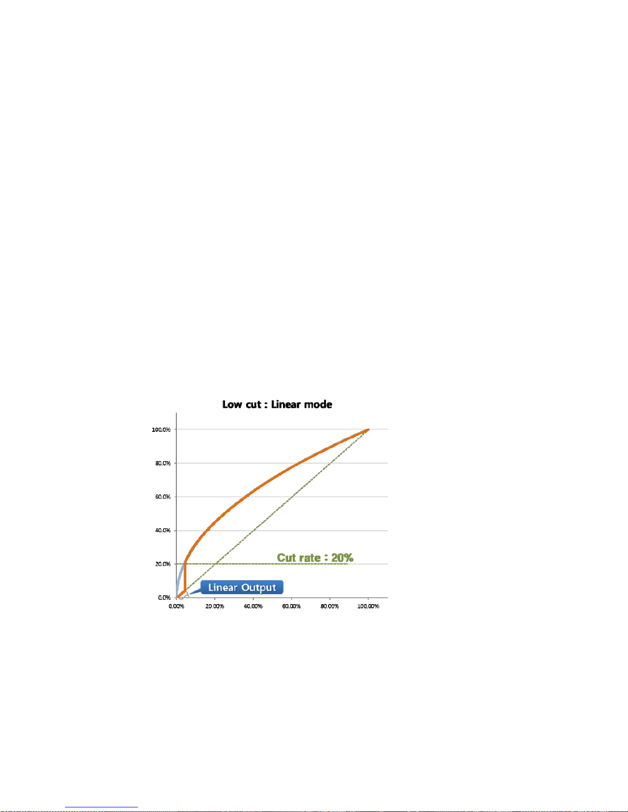
* If SQRT Transfer Function is chosen, output changes severely even by a small change to
input in the region of low pressure. Because this may cause distortion to input analysis, a
technique of applying non-SQRT Transfer Function is used when pressure is lower than a
certain value. This product supports this function by setting up Low cut mode.
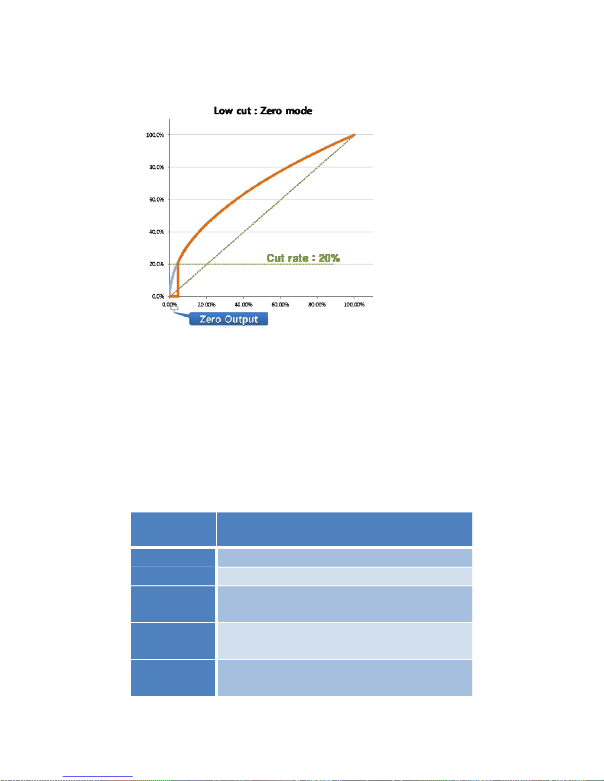
When Lowcut is set up as
Linear mode, apply linear
Transfer Function if
pressure is lower than Cut
rate.
Page 30
APT3500 Smart Pressure Transmitter Operation Manual M3500-EO1G
28 DUON System Co., Ltd.
When Low cut is set up as
Zero mode, Zero is printed
out if pressure is lower than
Cut rate.
Figure 3-9. Low cut mode comparison
- Change LCD Mode
- Executing the menu to put Zero+Span button.
- Moving to the next menu to put Zero button when 1 TRIM message appear.
- Moving to the next menu to put Zero button when 2 Setup message appear.
- Moving to the sub directory to put Span button when 3 LCD message appear.
- Executing the function to put Span button when 31 LCD-MD message appear.
- If LCD Mode set-up Function is performed, usable LCD modes are indicated in the 2nd line of
LCD, and indication contents are as follows:
Indication
Content
Explanation
NOR_RO
Normal Rotation Mode. PV, %, mA are indicated alternately.
NOR_PV
PV Mode. Only measured PV is indicated.
NOR_%
Percent Mode. Measured PV is indicated in Percent with
respect to Range.
NOR_mA
mA Mode. 4~20mA current values are indicated for
measured PV.
ENG_RO
Engineering Rotation Mode. Engineering PV, %. mA are
indicated alternately.
Page 31

APT3500 Smart Pressure Transmitter Operation Manual M3500-EO1G
29 DUON System Co., Ltd.
ENG_PV
Engineering PV Mode. Converted PV is indicated in the set-
up Engineering Range.
- Whenever ZERO Button is pushed, LCD Mode is changed, and after choosing the desired
mode, use SPAN Button to save set-up values.
- Decimal Place : Set up decimal place of the numerical value displayed on LCD.
- Executing the menu to put Zero+Span button.
- Moving to the next menu to put Zero button when 1 TRIM message appear.
- Moving to the next menu to put Zero button when 2 Setup message appear.
- Moving to the sub directory to put Span button when 3 LCD message appear.
- Moving to the next menu to put Zero button when 31 LCD-MD message appear.
- Executing the function to put Span button when 32 DEC-PL message appear.
- When Decimal Place function excuted, the type of decimal place will be appear on the
secondline of LCD as below.
Display Explanation Max. Value
AUTO
Target value will be displayed
automatically (Former Display Type)
9999
5-0
None decimal place
9999
4-1
Display one decimal place
9999.9
3-2
Display two decimal place
999.99
2-3
Display three decimal place
99.999
1-4
Display four decimal place
9.9999
- Firstly, 0.0 will be display on the first line of LCD.
- Decimal place will be change whenever put the Zero button. Saving the setting value to put
Span button after select the required decimal palce.
- The set value will be applicable for displaying PV value and Engineering value. 3-2 format will
be displayed for mA and % regardless any setting.
- LCD_OV message and current setting Unit will be displayed when over the LCD limitvalue.
- Change Engineering URV : Set up URV (Upper Range Value) which is used in LCD Engineering
Mode.
- Executing the menu to put Zero+Span button.
Page 32

APT3500 Smart Pressure Transmitter Operation Manual M3500-EO1G
30 DUON System Co., Ltd.
- Moving to the next menu to put Zero button when 1 TRIM message appear.
- Moving to the next menu to put Zero button when 2 Setup message appear.
- Moving to the sub directory to put Span button when 3 LCD message appear.
- Moving to the next menu to put Zero button when 31 LCD-MD message appear.
- Moving to the next menu to put Zero button when 32 DEC-PL message appear.
- Moving to the sub directory to put Span button when 33 ENG-MD message appear.
- Executing the function to put Span button when 331 EN-URV message appear.
- LCD displays the present set-up value and the highest input DIGIT flickers.
- The procedure of setting value is same as Zero Adjustment.
- Change Engineering LRV : Set up LRV (Lower Range Value) which is used in LCD Engineering
Mode.
- Executing the menu to put Zero+Span button.
- Moving to the next menu to put Zero button when 1 TRIM message appear.
- Moving to the next menu to put Zero button when 2 Setup message appear.
- Moving to the sub directory to put Span button when 3 LCD message appear.
- Moving to the next menu to put Zero button when 31 LCD-MD message appear.
- Moving to the next menu to put Zero button when 32 DEC-PL message appear.
- Moving to the sub directory to put Span button when 33 ENG-MD message appear.
- Moving to the next menu to put Zero button when 331 EN-URV message appear.
- Executing the function to put Span button when 332 EN-LRV message appear.
- LCD displays the present set-up value and the highest input DIGIT flickers.
- The procedure of setting value is same as Zero Adjustment.
- Change Engineering Unit
- Executing the menu to put Zero+Span button.
- Moving to the next menu to put Zero button when 1 TRIM message appear.
- Moving to the next menu to put Zero button when 2 Setup message appear.
- Moving to the sub directory to put Span button when 3 LCD message appear.
- Moving to the next menu to put Zero button when 31 LCD-MD message appear.
- Moving to the next menu to put Zero button when 32 DEC-PL message appear.
- Moving to the sub directory to put Span button when 33 ENG-MD message appear.
- Moving to the next menu to put Zero button when 331 EN-URV message appear.
- Moving to the next menu to put Zero button when 332 EN-LRV message appear.
- Executing the function to put Span button when 333 E-UNIT message appear.
- The 1
st
position in the LCD lower part flickers while letters are entered to be used as the LCD
Page 33

APT3500 Smart Pressure Transmitter Operation Manual M3500-EO1G
31 DUON System Co., Ltd.
Engineering Unit.
- Letter input method is the same as numerical input method except “not only number but also
letter and partly special character can be enter into each DIGIT”. Hence, enter in the same
procedure as in (4) Zero Adjustment.
- Engineering Unit entered through button manipulation gives the same result as User Define
Unit under the communication environment of STT30 or HHT (Handheld Terminal).
- Change Engineering Unit
- Executing the menu to put Zero+Span button.
- Moving to the next menu to put Zero button when 1 TRIM message appear.
- Moving to the next menu to put Zero button when 2 Setup message appear.
- Moving to the sub directory to put Span button when 3 LCD message appear.
- Moving to the next menu to put Zero button when 31 LCD-MD message appear.
- Moving to the next menu to put Zero button when 32 DEC-PL message appear.
- Moving to the sub directory to put Span button when 33 ENG-MD message appear.
- Moving to the next menu to put Zero button when 331 EN-URV message appear.
- Moving to the next menu to put Zero button when 332 EN-LRV message appear.
- Moving to the next menu to put Zero button when 333 E-UNIT message appear.
- Executing the function to put Span button when 334 E-TRF message appear.
- Until the desired Transfer Function, either "LINEAR" or "SQRT", is displayed on the LCD lower
part, push ZERO button repeatedly.
- If the desired Transfer Function is displayed, push SPAN Button to complete set-up.
- If “SAVE” is displayed, push SPAN Button to save set-up value.
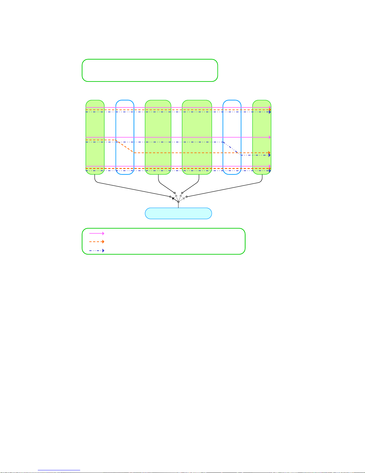
* This product can print out measured results in various ways on the LCD screen. LCD
Engineering Mode is the function that converts measured result to “numerical value with
different weight”and prints out on the LCD screen. LCD Engineering Mode sets up
Engineering Range separately, and maps measured result (0~100%) to Engineering
Range and prints out on LCD. For the measured value handling procedure in the LCD
Engineering Mode, refer to [Figure3-10]. It should be noticed that both Transfer Function
and ENG. Transfer Function cannot be simultaenously set up as SQRT.
Page 34
APT3500 Smart Pressure Transmitter Operation Manual M3500-EO1G
32 DUON System Co., Ltd.
0 kPa
[ Configuration Example ]
LRV = 0 kPa, URV = 200 kPa, Primary Unit = kPa
ENG. LRV = 0 Nm3/h, ENG. URV = 80 Nm3/h, ENG. Unit = Nm3/h
100 kPa
200 kPa
0%
50%
100%
70.7%
4mA
12mA
20mA
15.31mA
0 Nm3/h
40 Nm3/h
80 Nm3/h
PV 0~100% 4~20mA ENG. PV
Transfer
Function
Linear
SQRT
Linear
SQRT
ENG.
Transfer
Function
Transfer Function : Linear, ENG. Transfer Function : Linear
Transfer Function : SQRT, ENG. Transfer Function : Linear
Transfer Function : Linear, ENG. Transfer Function : SQRT
56.46 Nm3/h
LCD Output
Normal PV
Percent
mA
Engineering PV
Figure 3-10. Measurement value handling procedure
- Select Button Lock
- Executing the menu to put Zero+Span button.
- Moving to the next menu to put Zero button when 1 TRIM message appear.
- Moving to the next menu to put Zero button when 2 Setup message appear.
- Moving to the next menu to put Zero button when 3 LCD message appear.
- Moving to the sub directory to put Span button when 4 DEVICE message appear.
- Executing the function to put Span button when 41 B-LOCK message appear.
- Use ZERO button to choose either "LOCK" or "RELEAS" and, then, push SPAN.
- If "LOCK" is chosen, enter the previous password after messages of "INPUT", "OLD", and
"PASSWD". Then, enter new password after messages of "INPUT", "NEW", and "PASSWD", to
set up Button Lock (Transmitter’s initial password is "000000").
- If "RELEAS" is chosen, you can cancel Button Lock by entering the existing password after
messages of "INPUT" and "PASSWD".
Page 35

APT3500 Smart Pressure Transmitter Operation Manual M3500-EO1G
33 DUON System Co., Ltd.
-Letter input method is the same as numerical input method except “not only number but also
letter and partly special character can be enter into each DIGIT”. Hence, enter in the same
procedure as in (4) Zero Adjustment.
- If “SAVE” is displayed, push SPAN Button to save set-up value.
* If Button Lock is set up, you have to enter password entering into menu Tree after messages
of "INPUT" and "PASSWD", and if password is incorrect it is impossible to manipulate through
menu Tree.
* If wrong password is entered, "PASSER" is displayed and, then, input is cancelled.
- Master Reset
- Executing the menu to put Zero+Span button.
- Moving to the next menu to put Zero button when 1 TRIM message appear.
- Moving to the next menu to put Zero button when 2 Setup message appear.
- Moving to the next menu to put Zero button when 3 LCD message appear.
- Moving to the sub directory to put Span button when 4 DEVICE message appear.
- Moving to the next menu to put Zero button when 41 B-LOCK message appear.
- Executing the function to put Span button when 42 M-RST message appear.
- If SPAN Button is pushed after displaying of “SAVE", Transmitter is reset after a while
(Equivalent to turning on and off power).
- Change HART Polling Address : Set up Polling address for HART communication.
- Executing the menu to put Zero+Span button.
- Moving to the next menu to put Zero button when 1 TRIM message appear.
- Moving to the next menu to put Zero button when 2 Setup message appear.
- Moving to the next menu to put Zero button when 3 LCD message appear.
- Moving to the sub directory to put Span button when 4 DEVICE message appear.
- Moving to the next menu to put Zero button when 41 B-LOCK message appear.
- Moving to the next menu to put Zero button when 42 M-RST message appear.
- Executing the function to put Span button when 43 P-ADDR message appear.
- LCD displays the present Polling Address, which increases to 0~15 every time ZERO Button is
pushed. After choosing a Polling Address in the range of 0~15, push SPAN Button.
- If “SAVE” is displayed, push SPAN Button to save set-up value.
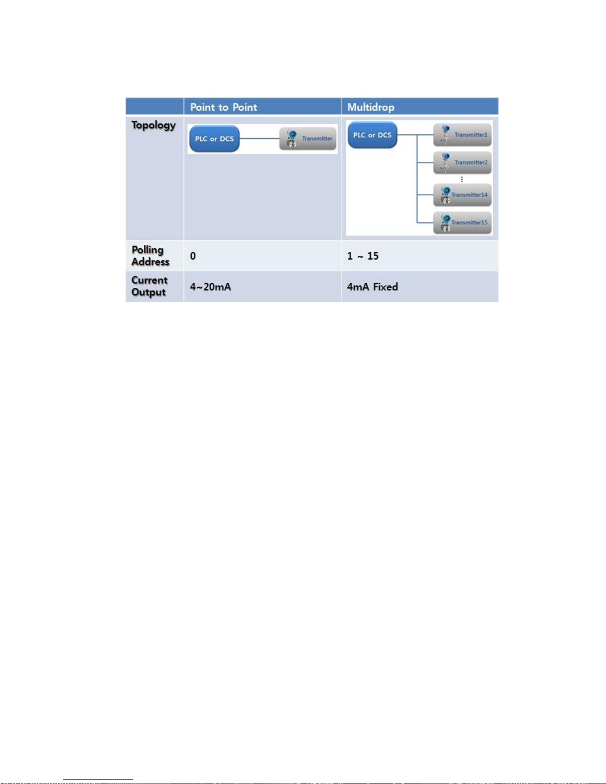
* If Polling Address is not 0, HART communication is operated in Multidrop, and at the time of
setting up Multidrop, M-icon is displayed on the LCD upper part.
Page 36
APT3500 Smart Pressure Transmitter Operation Manual M3500-EO1G
34 DUON System Co., Ltd.
[Figure 3-11 HART communication topology]
Page 37
APT3500 Smart Pressure Transmitter Operation Manual M3500-EO1G
35 DUON System Co., Ltd.
3.8 Shop Commissioning using HHT
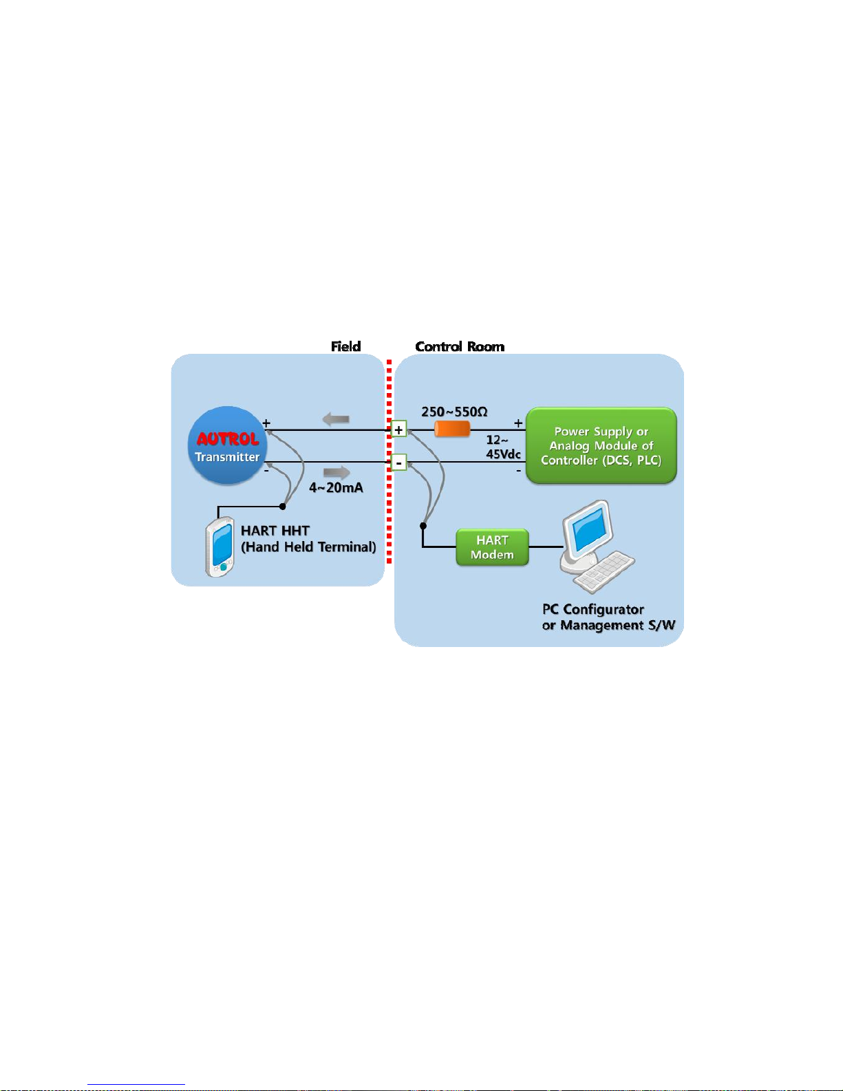
Commissioning consists of testing the transmitter, testing the loop, and verifying transmitter
configuration data. APT-3100 Pressure Transmitter may be commissioned using HHT of HART
supported either before of after installation.
▲ If you connect "TEST" pin, it's not communicated. If it doesn't exposed electronics circuits after
install, you must connect all Jumper of transmitter in the shop commissioning level. Analog output of
transmitter is 4~20 mA, thus it requires Power Supply at 24V (12 V ~ 45 Vdc) and Ampere meter for
measuring output current. You must connect 250~550 ohm resistor in Power Loop for HART
Communication and HHT or PC Configurator.
1) HTT(Hand Held Terminal) or PC Configurator may connected at any termination point in the
signal loop
2) HART Communication requires a loop resistance between 250~550 ohm @ 24Vdc.
3) Transmitter operates on 12 to 45.0 Vdc Transmitter terminal voltage.
[Applied Power]
12~45.0 Vdc for General operation
17.5~45.0 Vdc for HART Communication (@250ohm)
[Fig
ure 3-5 Connection the transmitter to
Page 38

APT3500 Smart Pressure Transmitter Operation Manual M3500-EO1G
36 DUON System Co., Ltd.
Chapter 4 Installation
4.1 Overview
The information in this chapter 4 covers installation considerations. Dimensional drawings for Model
APT-3100 variation and mounting configuration are included in this chapter.
4.2 Safety Message
Procedures and instructions in this chapter may require special precautions ensure the safety of the
personnel performing the operation. Information that raises potential safety issues is indicated by a
warning symbol(▲). Refer to the following safety messages before performing an operation proceeded
by this symbol.
4.3 Warning
▲ Warning
Explosion can result in death or serious injury :
◈ Do not remove the transmitter covers in explosion environments when the circuit is alive.
◈ Both transmitter covers must be fully engaged to meet explosionproof requirements
▲ Warning
Electrical can result in death serious injury:
◈ The qualification which is educated only the person whom it prepares will be able to establish the
transmitter.
▲ Warning
Process leaks can cause death or serious injury:
◈ Install and tighten before applying pressure. Ift you don’t llike this, it can cause process leaks.
▲ Warning
Electrical shock can result in death or serious injury. If you install high voltage environment or false
condition, power line and lead will be apprered high voltages.
◈ Avoid contact with the leads and terminals.
4.4 Commissioning on the bench with Hand-Held Terminal
Page 39
APT3500 Smart Pressure Transmitter Operation Manual M3500-EO1G
37 DUON System Co., Ltd.
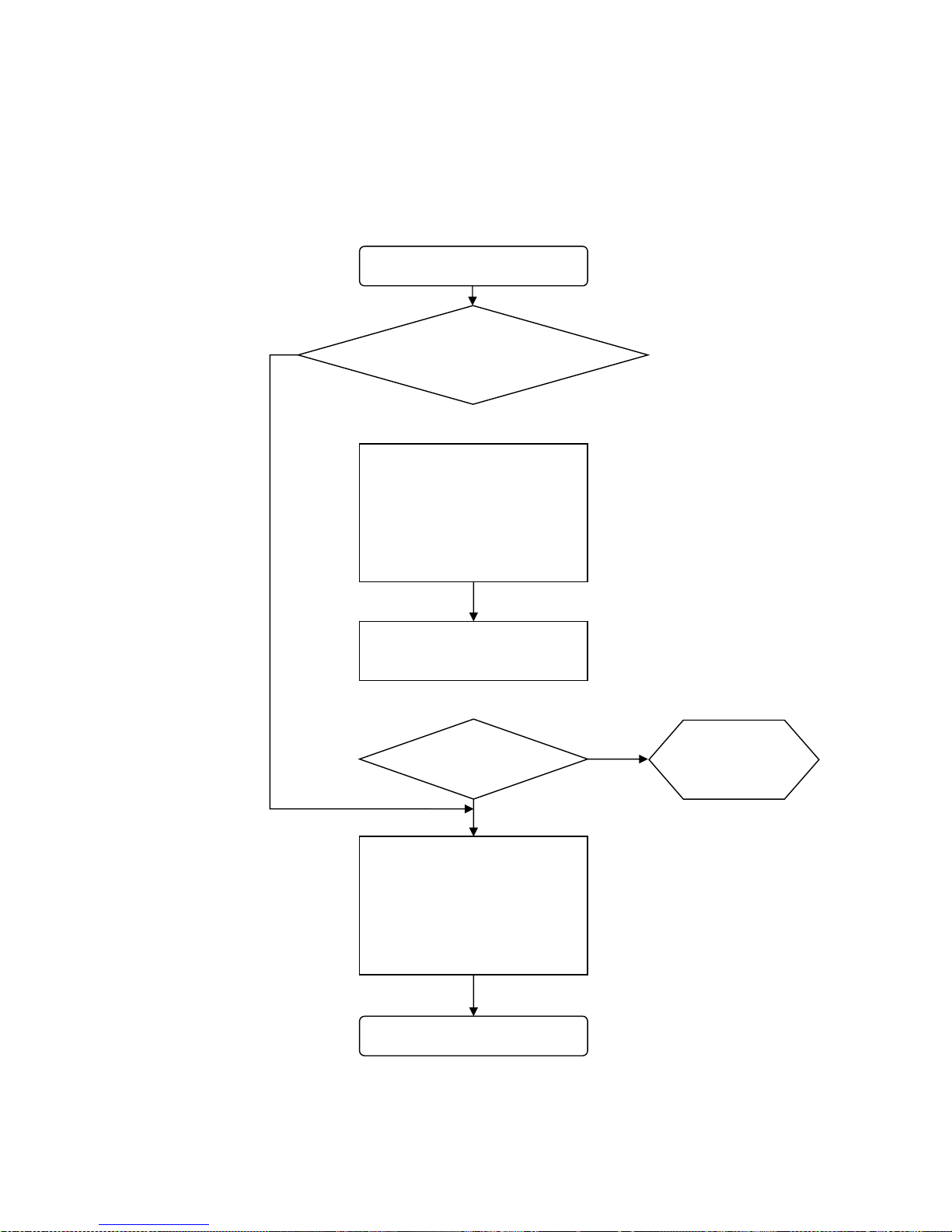
After and before installation, you can handle upon commissioning. However, for correctly handling and
knowing the function, before installation you have to handle upon commissioning on the bench with
Hand-Held Terminal.
Start
Field Install
a) Jumper/Switch Setup
b) Transmitter take up
c) Transmitter leads
e) Transmitter for Power Supply
f) Process Leak Check
End
Do you want
Basic Setup
a) Unit Setup
b) Range Setup
c) Damping Setup
d
)
T
ransmitter Function Setu
p
Verify
a) Pressure Support
Yes
No
Do you satisfy Spec? Maintenance
[Figure 4-1 Installation Flow Chart]
Page 40

APT3500 Smart Pressure Transmitter Operation Manual M3500-EO1G
38 DUON System Co., Ltd.
4.5 General Considerations
This transmitter uses the capacitive pressure sensor. If it changes the pressure sensor, capacitive
pressure is changed minutely.
It transfer electrical signal minutely to 4~20mA analog signal. Thus mount the transmitter close to the
process and use a minimum of piping to achieve best accuracy. However keep in mind the need for
easy access, safety of personnel, practical field calibration, and a suitable transmitter environment.
In general, install the transmitter so as to minimize vibration, shock, and temperature fluctuations.
4.6. Electrical Considerations (Power Supply)
The transmitter housing composes of two parts. One side is electronics circuit, and other side is
Terminal Block. Terminal Block side is transmitter's frontside and is indicated " Field Terminal" in
transmitter housing external. Open this side's housing cover, there is Terminal Block in housing inside.
Consider to this Terminal Block polarity, connect to Transmitter's Power Supply. Configurator supported
HART connects to "COMM" pin in Power Supply downside. In the field Indicator connects to "TEST"
pin.
4.6.1 Power Supply
In the transmitter's power supply Input Current Voltage is currently DC voltage between DC 12
volt ~ 45 volt and power supply's ripple is not up to 2%. Loop resistance means all resistor sums
in loop.
In case of using Intrinsic Safety Barrier, same includes resistor of barrier.
Max. Loop Resistance [Ω] = (E-12) [vdc] / 0.022 [mA]
Here, loop resistance is preferable at 250 ~ 550Ω (24 Vdc) for the HART communication.
4.7. Wiring
4.7.1 Caution of Wiring
(1) Install cable in the far from electrical noise resources like capacitive transformer, motors
power supply as soon as possible.
(2) Before wiring put out electrical lead connect cap.
(3) All screw-lined portions paste suture for waterproof. (It promotes the silicon type that is not
hardened.)
(4) Don't lead signal line to power line in same duct for no received noise signal.
(5) The explosion-proof transmitter in order to maintain the explosion-proof quality of the
corresponding transmitter effectively follows in the demand explosion-proof specification that
is provided and must be lead.
4.7.2 Selecting the Wiring Materials
(1) Use over 600V PVC shielded wire or standard lead line of same class or cable. (In order to
ensure proper communication use 24 AWG or lager wire, and do not exceed 1500 meters.)
(2) Use the shielded wire in electrical noise effected area.
Page 41
APT3500 Smart Pressure Transmitter Operation Manual M3500-EO1G
39 DUON System Co., Ltd.
COM M TESTCOMM TEST
(3) At the higher or lower temperature area than ambient temperature it uses the wire or the
cable that is suitable like that temperature.
(4) You have to use suitable wire, cable in environment like oil, solvent, toxic gas or liquid.
(5) Terminal process of lead line must use to not soldered terminal lug. Recommend isolating lead
end terminal using contract tube.
4.7.3 Connections of External Wiring to Transmitter Terminal Box
Wiring method is following this.
▲ (1) Open the housing cover indicated "FIELD TERMINAL". In explosion environment when circuit
is powered on, don't open the covers.
▲ (2) Connect the power supply in the terminal indicated "+PWR"(left terminal) and "-" power
supply in the central terminal. Don't connect "+" power supply in "+" terminal of the point
indicated "TEST". It will be damage to test diode used to connecting TEST terminal.
(3) Seal and close the non-using Conduit Connection Part for severe humidity and explosion on
the terminal box of housing.
(4) Transmitter power is supplied to Signal Wiring. So, don't install near to Signal Wiring with
Power Wiring or near to Power Apparatus. In case of ground signal, ground the signal loop's
one side and other side is not grounded. Promote to ground "-" side of power.
(5) For the better adjustment completely turn Screw terminal.
(6) Again close the transmitter cover. Specially in case of using in explosion area, you must to
satisfy requirement about explosion.
[Note]
Don't supply high voltage (AC power) in transmitter leads. It can be caused damages to
transmitter.
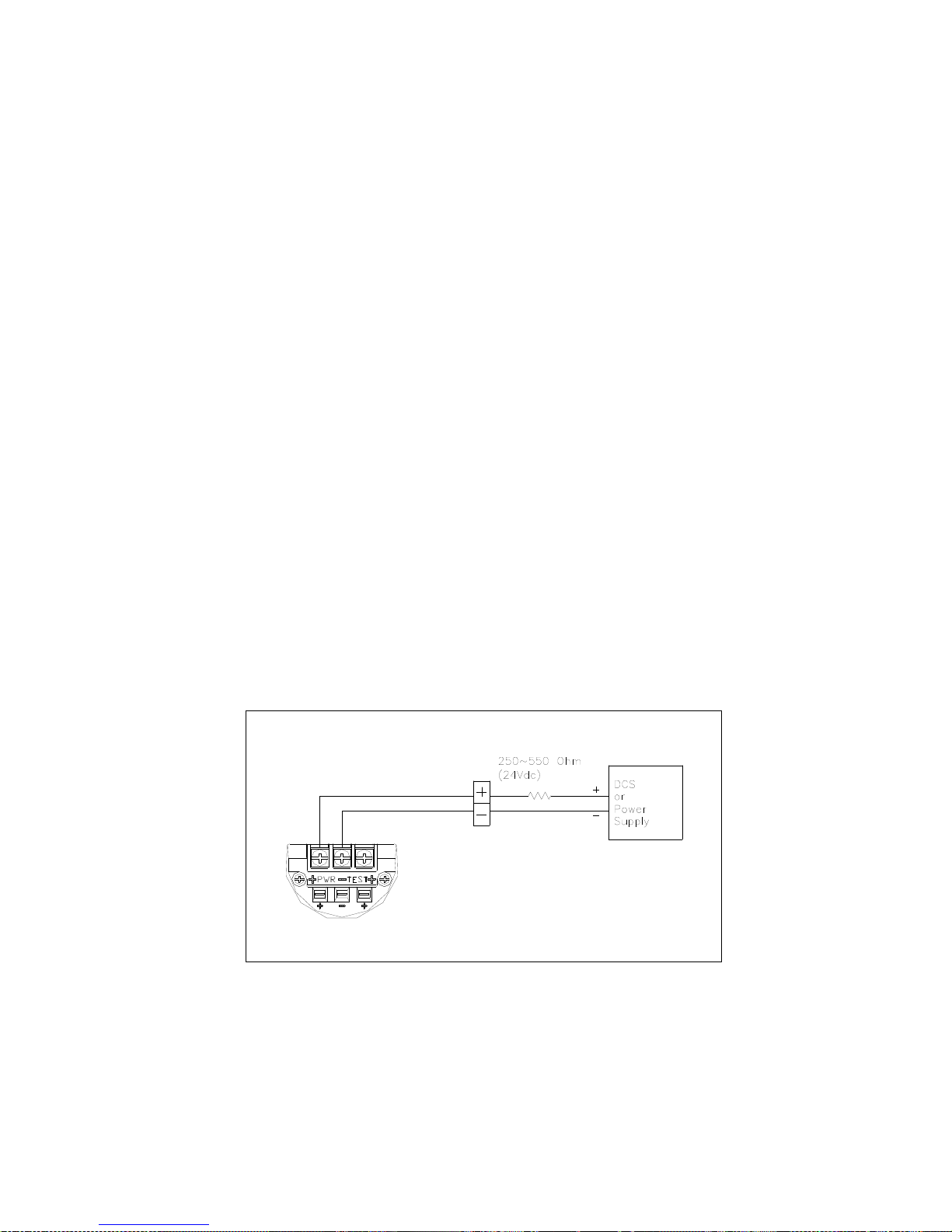
(7) You have to connect 250~600 W Loop Resistor in Current Loop(between Power Supply and
Transmitter) for HART Communication HART. Following Figure 4-2 about conection of Current
Loop.
Figure 4-2 Connection with Terminal Board of Transmitter
Page 42
APT3500 Smart Pressure Transmitter Operation Manual M3500-EO1G
40 DUON System Co., Ltd.
2
2
DCS or
Power Supply
Local Indicator
or Current Meter
+
-
-
+
1
Internal Ground
Cable Entry
2
1
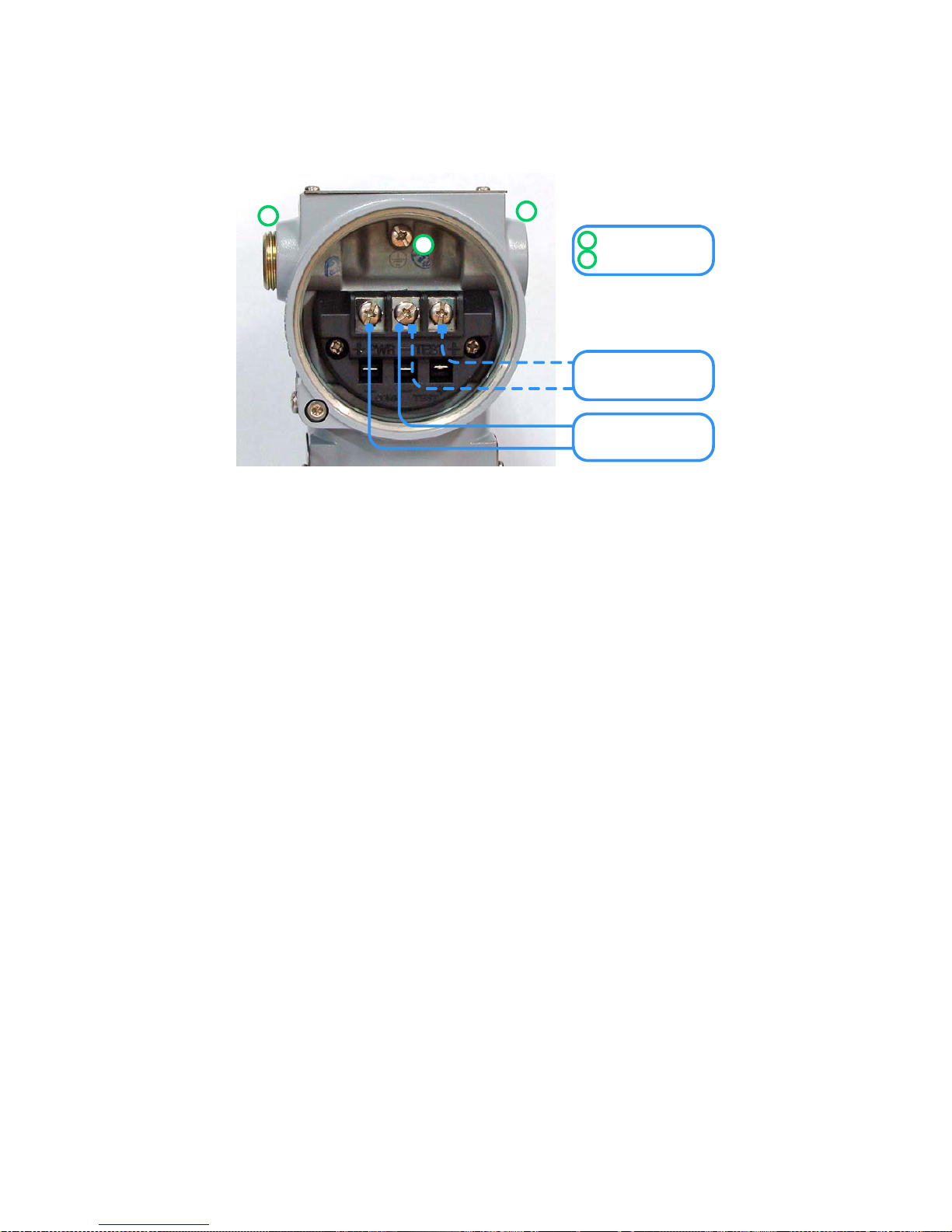
Figure 4-3 Picture of Terminal Board of Transmitter
Page 43
APT3500 Smart Pressure Transmitter Operation Manual M3500-EO1G
41 DUON System Co., Ltd.
4.7.4 Wiring
▲ Warning
Explosion can result in death or serious injury:
◈
Do not remove the transmitter covers in explosion environments when the circuit is alive.
◈ Before connection HHI in explosion zone, confirm that the configure device has to be installed by
intrinsic safety regulations.
◈ Both transmitter covers must be fully engaged to meet explosion proof requirements
A. Loop Configuration
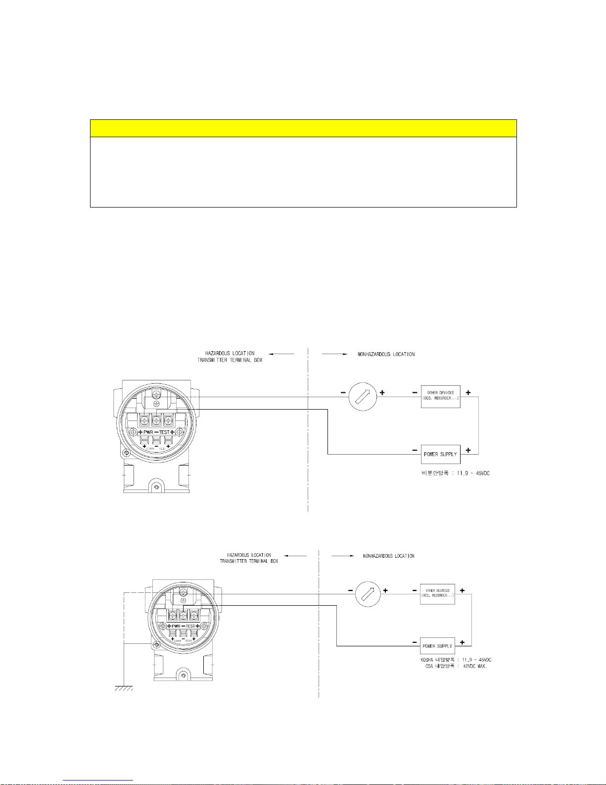
AUTROL Series Transmitters use a two-wire system for power supply, 4~20mA analog signal
transmission and HART digital transmission.
DC Power Supply is required for the transmitter loop. The Transmitter and distributor are
connected as shown below.
(1) Non-Explosionproof / Flameproof Type
(2) Explosionproof Type
Page 44
APT3500 Smart Pressure Transmitter Operation Manual M3500-EO1G
42 DUON System Co., Ltd.
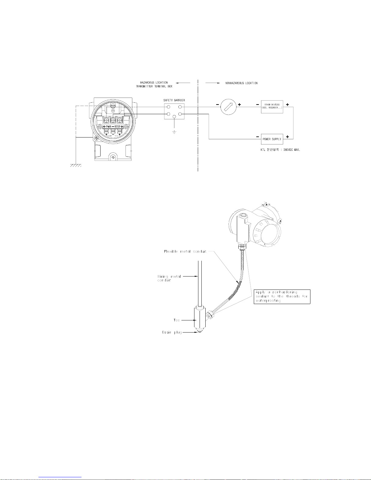
(3) Intrinsical Safety Type
[Figure 4-3 Connection between Transmitter and Power Supply]
B. Wiring Installation
(1) General-use Type and intrinsically Safe Type
Make cable wiring using metallic conduit or
Waterproof cable glands.
o. Apply a non-hardening
sealant to the terminal
box connection port
and the threads on the
flexible metal conduit
for the waterproofing.
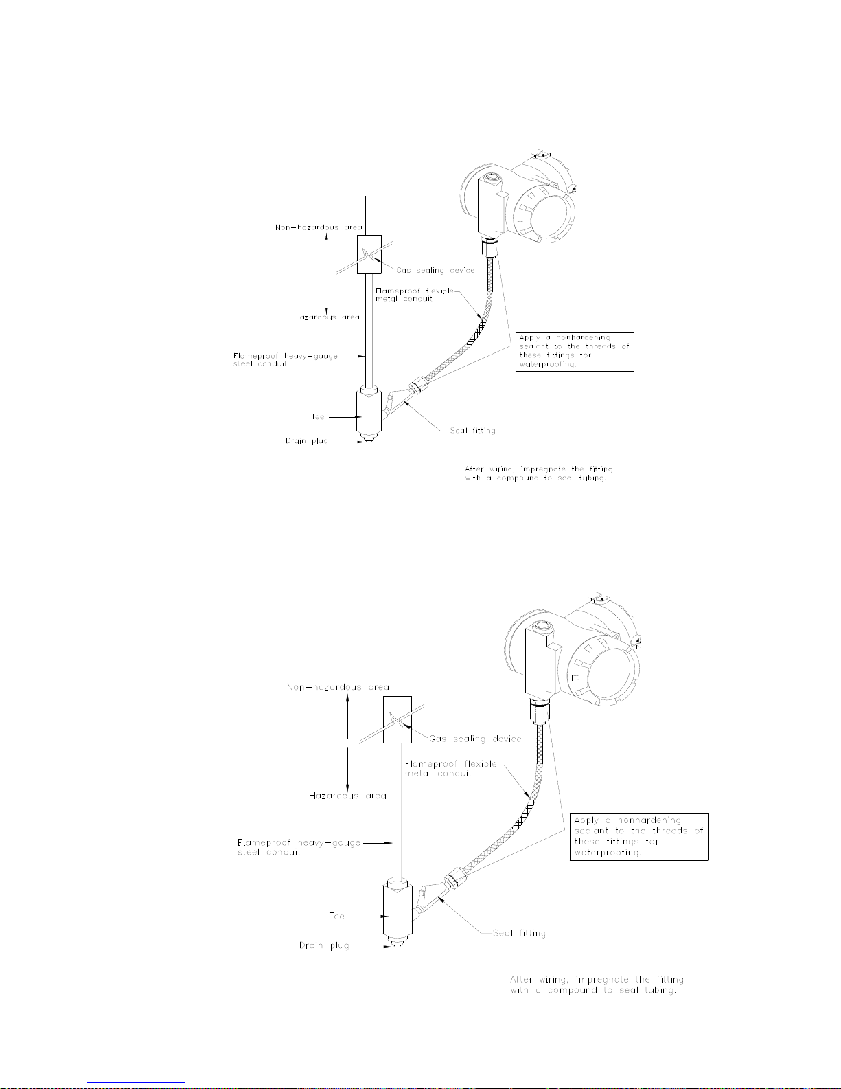
(2) KOSHA Flameproof Type
Wire cables through a flameproof packing adapter, or using a flameproof metal conduit.
(a) Wiring cable through flameproof packing adapter for KOSHA flameproof type (see
Figure 4-4b)
◇ Use only flameproof packing adapter by KOSHA.
◇ Apply a non-hardening sealant to the terminal box connection port and to the
threads on the flameproof packing adapter for waterproofing
◇ Mounting flameproof packing adapter to the terminal box.
o. Screw the flameproof packing adapter into the terminal box until the O-ring touches
the terminal box wiring port (at least 5 full turns), and tighten the lock net.
[Figure 4-4a
Typical Wiring using
Flexible Metal Conduit]
Page 45
APT3500 Smart Pressure Transmitter Operation Manual M3500-EO1G
43 DUON System Co., Ltd.
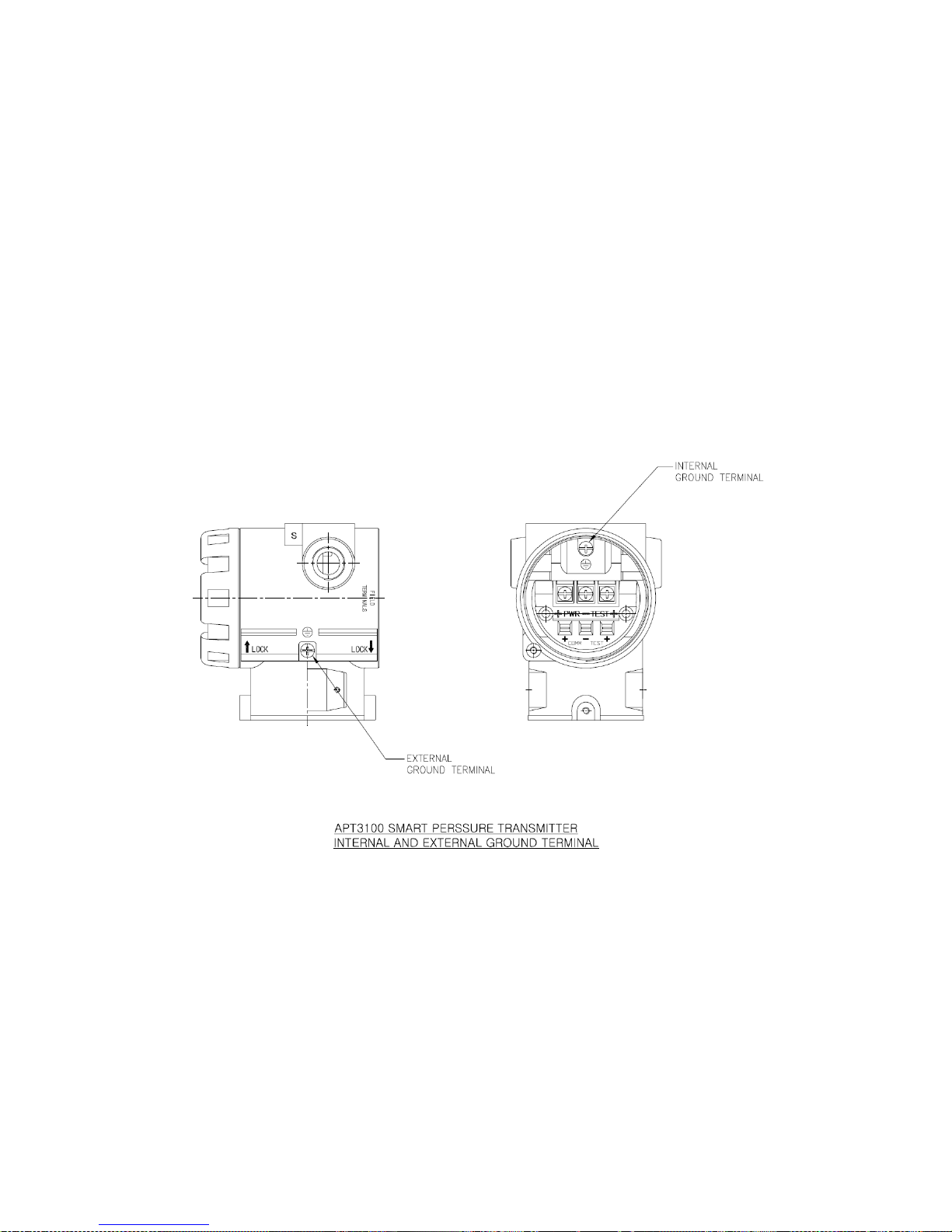
(b) Flameproof metal conduit wiring (Figure 4-4c)
◇ A seal fitting must be installed near the terminal box connections port for a sealed
construction.
◇ Apply a non-hardening sealant to the threads of the
terminal box connection box, flexible metal
conduit and deal fitting for
waterproofing.
[Figure 4-4b
Typical Wiring using Flameproof Packing Adapter]
[Figure 4-4c
Typical Wiring using Flameproof Metal Conduit]
Page 46
APT3500 Smart Pressure Transmitter Operation Manual M3500-EO1G
44 DUON System Co., Ltd.
4.7.5 Grounding
(a) Grounding should satisfy KS requirements (grounding resistance, 10 Ohm or less). Grounding
is required below 10 Ohm for explosionproof and intrinsic safety.
[Note] In case of with Built-in Lightening Protector, Grounding should satisfy Special KS
requirements (grounding resistance, 10 Ohm or less)
(b) There are ground terminal on the inside and outside of the terminal box. Either of these
terminals may be used.
(c) Use 600V grade PVC insulated wire for grounding.
Page 47
APT3500 Smart Pressure Transmitter Operation Manual M3500-EO1G
45 DUON System Co., Ltd.
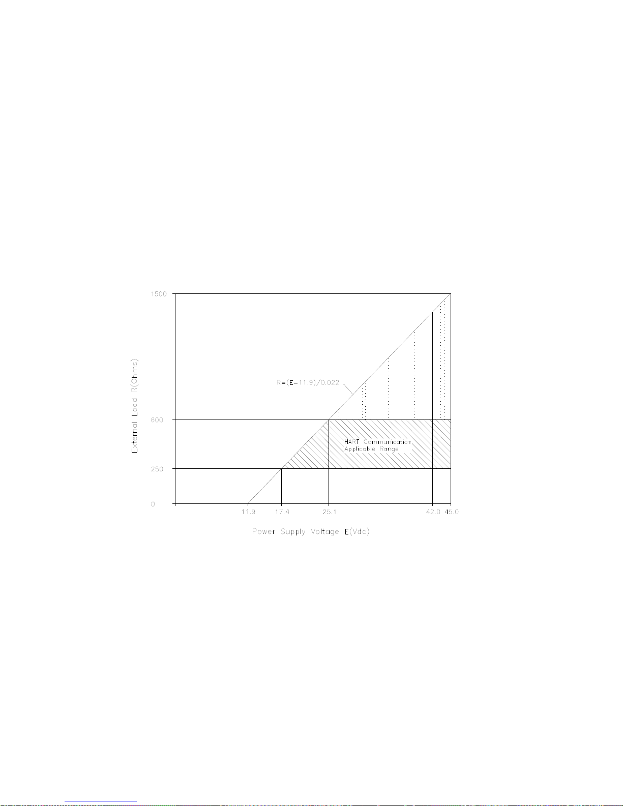
4.7.6 Power Supply Voltage and Load Resistance
When configuring the loop, make sure that the external load resistance is within the range in the
figure below. Since the voltage of transmitter terminal input is same as follows.
Voltage Rating : 24Vdc
General Standard : 12 to 45 Vdc
Hart Communication : 17.5 to 45 Vdc
KOSHA Explosionproof : 12 to 45 Vdc
CSA Explosionproof : 17.5 to 42 Vdc max.
And maximum loop current is 24mA, Load resistance R:
R = (E-12) / 0.022 (E = Power Supply Voltage)
[Note] In case of an intrinsically safe transmitter, external load resistance includes safety barrier
resistance.
Page 48
APT3500 Smart Pressure Transmitter Operation Manual M3500-EO1G
46 DUON System Co., Ltd.
4.8 Mechanical Considerations
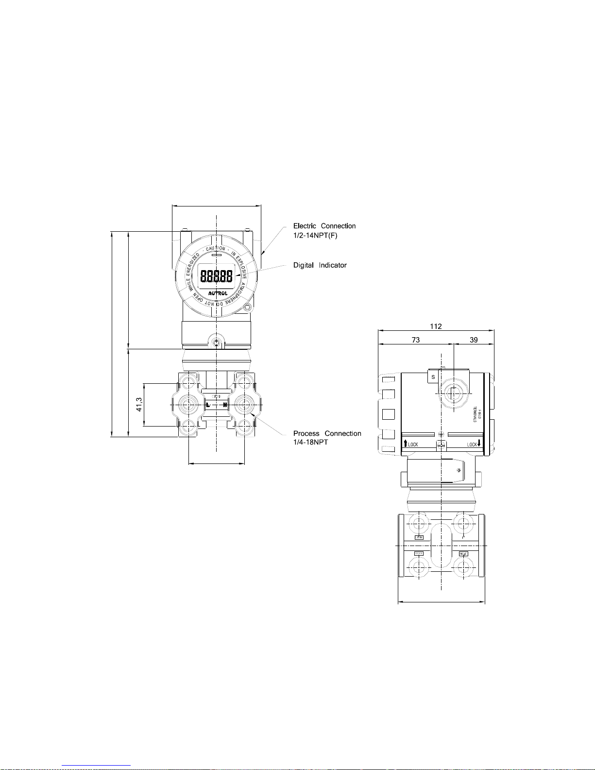
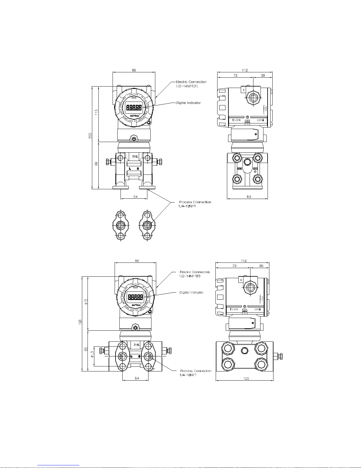
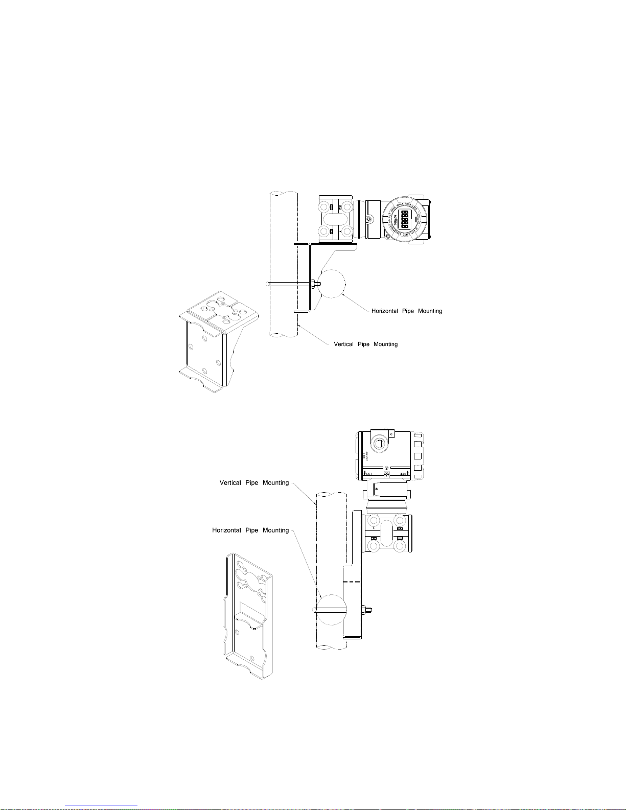
Figure 4-3 is transmitter dimensional drawings of APT3500. A mounting example and dimensional
drawings is shown in Figure 4-4.
[ Standard Model ]
86
54
198
11385
54
84
Page 49
APT3500 Smart Pressure Transmitter Operation Manual M3500-EO1G
47 DUON System Co., Ltd.
[ MP Flange ]
[ High Static Pressure Model ]
Figure 4-6. Model APT3500 Outline Dimension Drawing
Page 50
APT3500 Smart Pressure Transmitter Operation Manual M3500-EO1G
48 DUON System Co., Ltd.
Figure 4-7. Typical Bracket Mounting
Page 51
APT3500 Smart Pressure Transmitter Operation Manual M3500-EO1G
49 DUON System Co., Ltd.
50
122
332
210
47
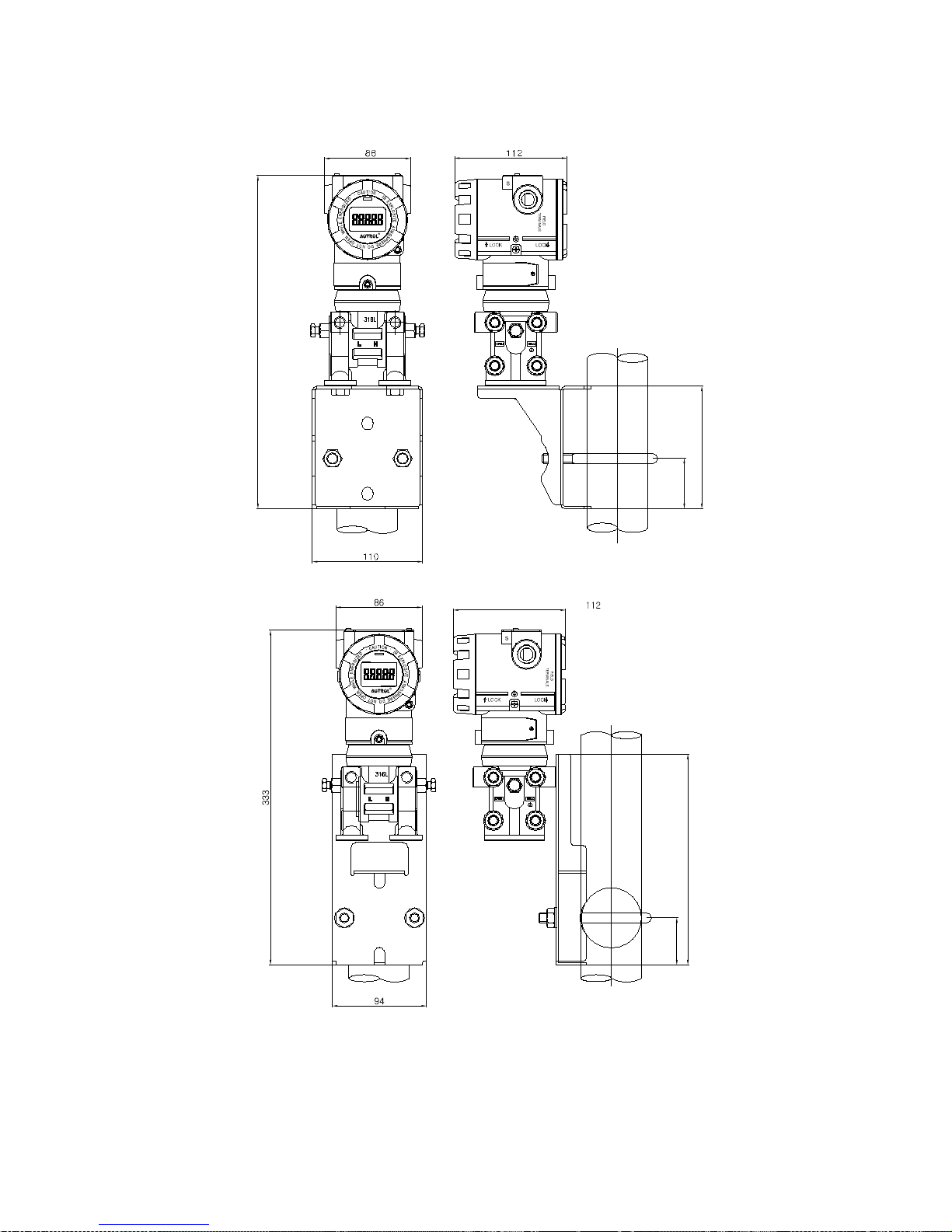
Figure 4-8. MP Option Bracket Mounting
Page 52
APT3500 Smart Pressure Transmitter Operation Manual M3500-EO1G
50 DUON System Co., Ltd.
4.8.1 Mounting
To use the cadence carrier from the environment where the vibration is heavy and must install
the transmitter. In the environment where the vibration is heavy you will have to install the
transmitter by using an assistant support. In the case of severe vibration, promote to mount on
pipe using a mounting bracket as option.
4.8.2 Consideration of Transmitter Access
When selecting the establishment location or a place of the transmitter, it treats the transmitter
it probably is a location that is convenient must consider.
① Rotation of housing: housing can be rotated up to 90°.
② Terminal sides of transmitter: location ease us terminal space where be able to pull out
transmitter cover
③ Circuits side of transmitter: the space where there is a possibility of treating a electronic
circuit / the space where be able to pull out transmitter cover / If LCD meter is installed, it
requires extra space.
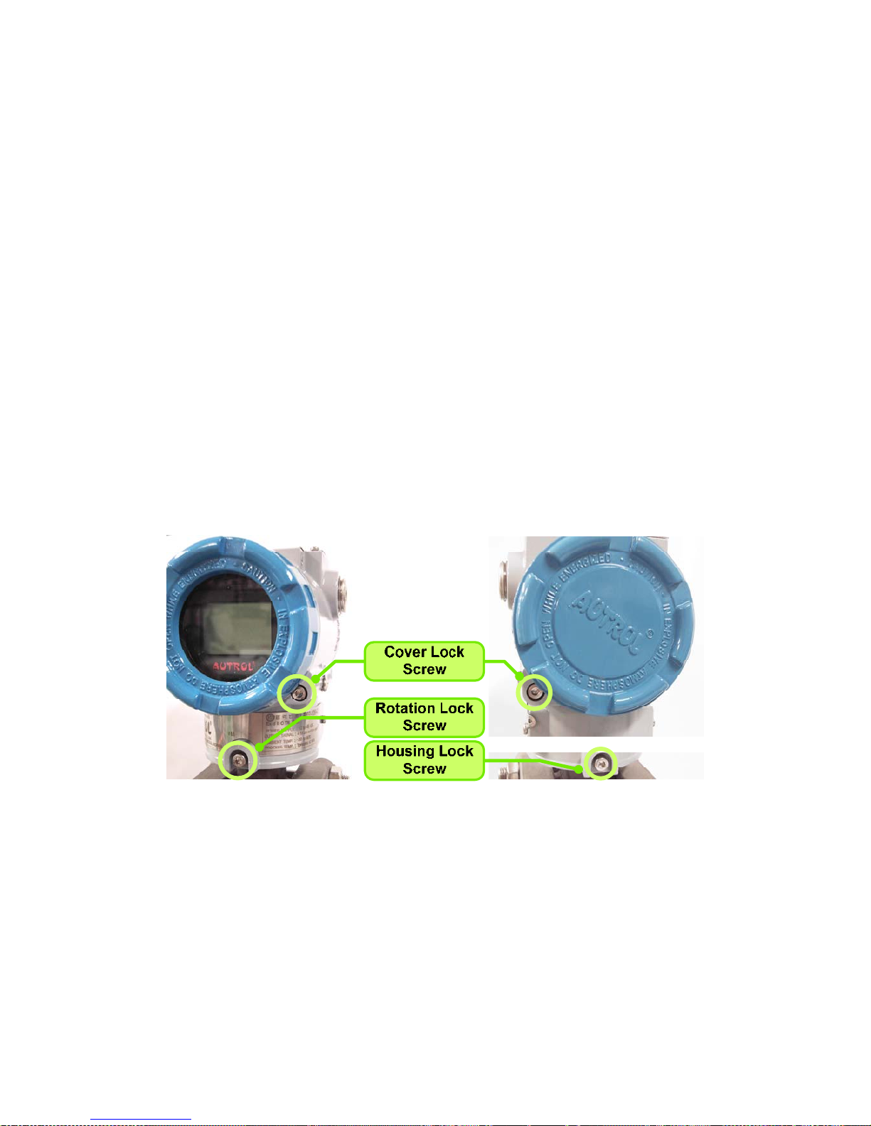
4-8-3. Housing Rotation and Lock Screw
Figure 4-8. Lock Screw
After Transmitter installation, housing can be rotated for wiring work or adjusting indication
direction of indicator. To rotate housing, loosen Rotation Lock Screw and rotate housing to the
desired direction. After completing housing direction adjustment, do not forget to tighten
Rotation Lock Screw to fix housing.
<Note> Housing is mechanically designed to be rotated up to 360°. In case of forced
rotation exceeding the limit, Transmittermay be damaged.
Page 53

APT3500 Smart Pressure Transmitter Operation Manual M3500-EO1G
51 DUON System Co., Ltd.
After completely removing Rotation Lock Screw and Housing Lock Screw, it is possible to
separate housing and sensor body of Transmitter by rotating housing. But, internal electronic
boards should be removed in advance before separating housing and sensor body.
Cover Lock Screw fixes the front and rear covers to prevent them from loosening. Fully
loosened, the Screw is stuck to the Cover side and Cover is fixed not to turn. Closing Cover Lock
Screw again, you can open it by turning Cover.
4.9 Environmental Considerations
4.9.1 Effect of Ambient Temperature
You have to install at -20℃~60℃ (-4~180℉), operating ambient temperature range. If predicted
heat seems to exceed or equivalent to ambient temperature range limit, you have to consider
additional method to cutoff the process heat.
4.9.2 Environment of toxic, moisture
Housing of APT-3100 can be protected to moisture or toxic material. Electronic circuit side is
separating from terminal side. When O-ring Seal cover covers, it is intrinsic safety. But, some drip
could penetrate to the housing of transmitter through conduit pipeline. Therefore, transmitter
should be set up over the position of conduit pipe for preventing drip.
4.9.3 Installation of dangerous place
Transmitter is designed to explosion-proof housing. Installation environment of transmitter must
be confirmed explosion-proof specification.
Page 54

APT3500 Smart Pressure Transmitter Operation Manual M3500-EO1G
52 DUON System Co., Ltd.
Chapter 5 On-line Operation
5.1 Overview
This chapter describes to configure function of APT3500 SMART Pressure Transmitter. Transmitter can
be configured to On-Line or Off-Line mode. In On-Line Configuration Mode, you must connect
configuration such as HHT (Hand Held Terminal), etc. Configuration data inputs in Working Register of
HHT and this data is sent to corresponding transmitter.
5.2 Safety Message
Send operation. Do specially notice for safety of operator. In damage and place required specially
safety, We indicate Warning symbol(▲). When you operate work of Warning symbol, follow Safety
Message.
5.2.1 Warning
▲ Warning
Explosion can result in death or serious injury:
◈ Do not remove the transmitter covers in explosion environments when the circuit is alive.
◈ Before connecting HHT in explosion zone, confirm that the configure device has to be installed by intrinsic
safety regulations.
◈ Both transmitter covers must be fully engaged to meet explosion-proof requirements
▲ Warning
Electrical shock can result in death or serious injury. If you install high voltage environment or false
condition, power line and lead will be appeared high voltages.
◈ Avoid contact with the leads and terminals.
5.2.2 Configuration current to passive mode
In the case of short Current Loop, send or request data to change transmitter output you must
configure Current Loop to passive mode. Don't believe in message indicating HHT, must configure
Current Loop to passive mode with other operation.
5.3 Configuration Data Review
In case of install transmitter in fact site, before operate transmitter reexamine and certify whether
configuration data correspond with fact application environment.
Page 55

APT3500 Smart Pressure Transmitter Operation Manual M3500-EO1G
53 DUON System Co., Ltd.
5.4 Check Output
Before other handle transmitter to on-line, you must examine and confirm whether transmitter
currently operate and suitably configure progress variable.
5.4.1 Process Variable
We use two progress variable in APT-3100 SMART Pressure Transmitter pressure value is Primary
Variable and temperature value of pressure value configure SV(Secondary Variable) with fixed
value.
Moreover this PV value ouputs with 4~20mA analog value.
5.5 Basic Setup
You must configure correlation variable for operating currently transmitter.
5.5.1 Select Sensor Range
Pressure range to measure is depended Range Code of sensor. This value is classified from
pressure sensor module automatically.
5.5.2 Set Output Units
Select from the following engineering units:
Unit: kPa, kg/cm2, bar, psi, mmH2O etc
5.5.3 Rerange
Set the Zero and Span of 4~20mA analog output.
5.6 Detailed Setup
5.6.1 Set Fail Mode
When sensor is wrong or microprocessor of transmitter doesn't operate normally in order to
outputs current value of High or Low.
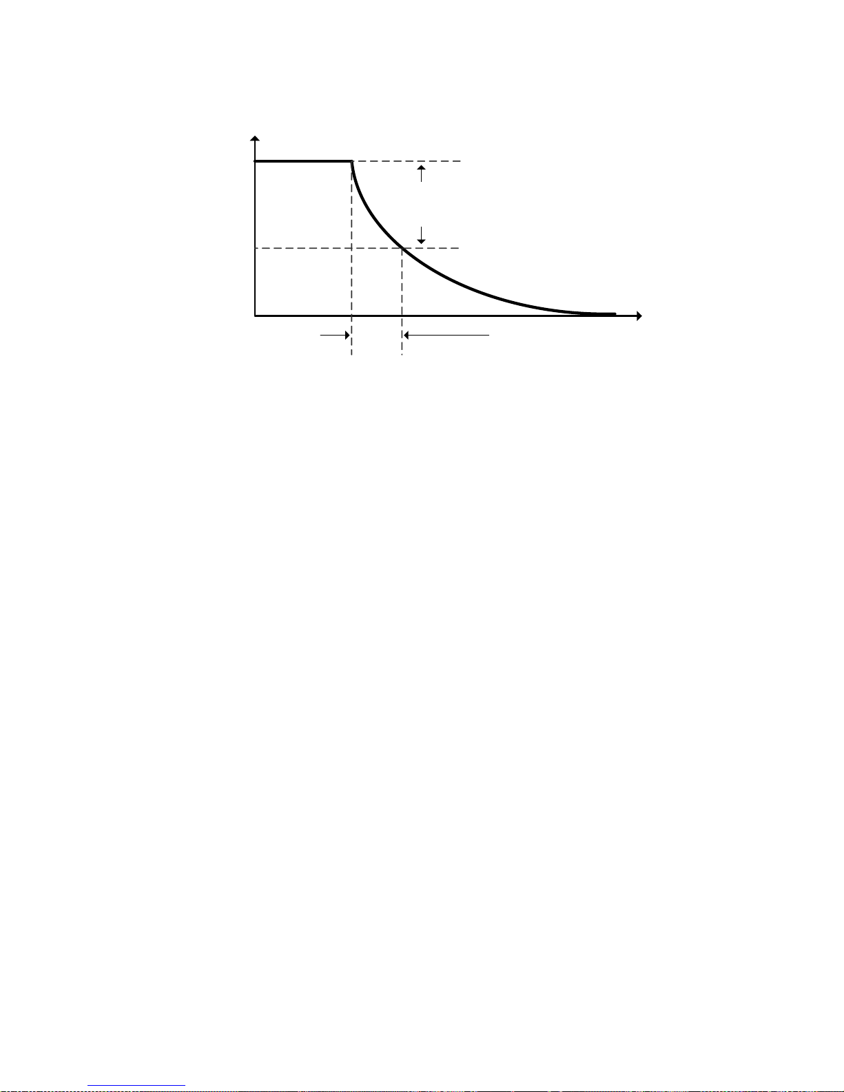
5.6.2 Set Damping Time
The sensor input value changes the response time of the transmitter to smooth variations in
output readings caused by rapid changes in input. Determine the appropriate damping setting
based on the necessary response time, signal stability, and other requirements of the loop
dynamics of your system. The default damping value is 1.0 seconds, and can be reset to damping
values between 0 and 60 seconds.
Page 56
APT3500 Smart Pressure Transmitter Operation Manual M3500-EO1G
54 DUON System Co., Ltd.
20mA
9.89mA
4mA
63% of
change
Time(seconds)
Damping
Second
[ Graph of Damping Second ]
5.7 Configuration of Information Variable
5.7.1 Set Tag
Tag variable is better easy method to classify to transmitter in multi transmitter install
environment. Tag Character can be used to 8 word of English/number.
5.7.2 Set Messages
When use several transmitter, user can define for classification each transmitter and use 32 words
of English/number. This message is saved in EEPROM of transmitter.
5.8 Configuration of Breakdown Diagnostic Function
5.8.1 Loop Test
The Loop Test verifies the output of the transmitter, the integrity of the loop, and the operations
of any recorders or similar devices installed loop. Perform the following procedure for a loop test.
① Connect a reference meter to the transmitter.
② Select the Loop Test of HHT and operate the Loop Test.
③ Select output current ( 4mA/20mA/etc )
④ If the readings match, then the transmitter and the loop are configured and functioning
properly. If the readings do not match, then you may have the current meter attached to the
wrong loop, there maybe a fault in the wiring, the transmitter may require an output trim, or the
electrical current meter may be malfunctioning.
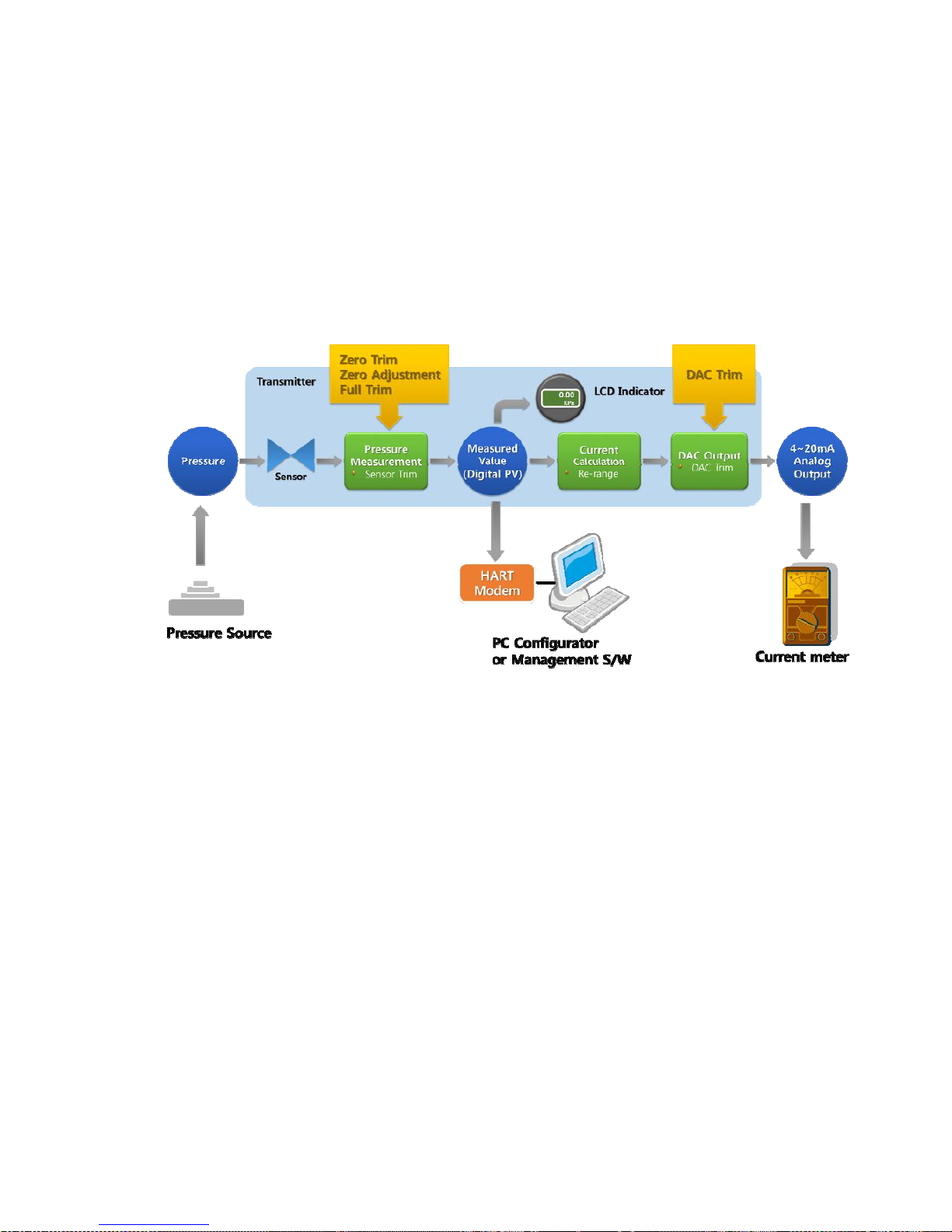
5.9 Calibration
Scaled system implement by calibrating the transmitter. Trim function have several function for the
Page 57
APT3500 Smart Pressure Transmitter Operation Manual M3500-EO1G
55 DUON System Co., Ltd.
calibration. Smart transmitters operate differently than analog transmitter. A Smart transmitter uses
a microprocessor that contains information about the sensor's specific characteristics in response to
pressure and temperature inputs for calculating Process Variable. The trim and rerange functions
also differ. Reranging sets the transmitter analog output to the selected upper and lower range
points and can be done with or without an applied pressure. Reranging does not change the factory
characterization curve stored in the microprocessor. Sensor trimming requires an accurate pressure
input and adds additional compensation that adjusts the position of the factory characterization
curve to optimize transmitter performance over a specific pressure range. Rerange functions
provides ability to readjust the 4~20mA points sensor inputs.
Figure 5-2. Calibration Environment
Detailed Calibration Procedure is as follows:
1) In the complete vent mode without pressure approval, check measured value of HHT or PC Configurator.
2) After approving the pressure to be checked (in general URV) from the pressure source, check measured
value of HHT or PC Configurator and compare it with approved pressure.
3) After examining measured values, if the error turns out to be offset component execute Zero Trim or Zero
Adjustment, and if slope is changed execute Full Trim. After Trim, check measured values again.
4) In the same method, check ampere meter in the vent mode and pressure approval mode.
5) In the event of error to measured values, check out the Transmitter set-up state, such as set-up range (URV,
LRV), Transfer function, and Lowcut.
6) In the event of error to ampere meter even after checking set-up value, execute DAC Trim. After Trim,
check measured values again.
Page 58
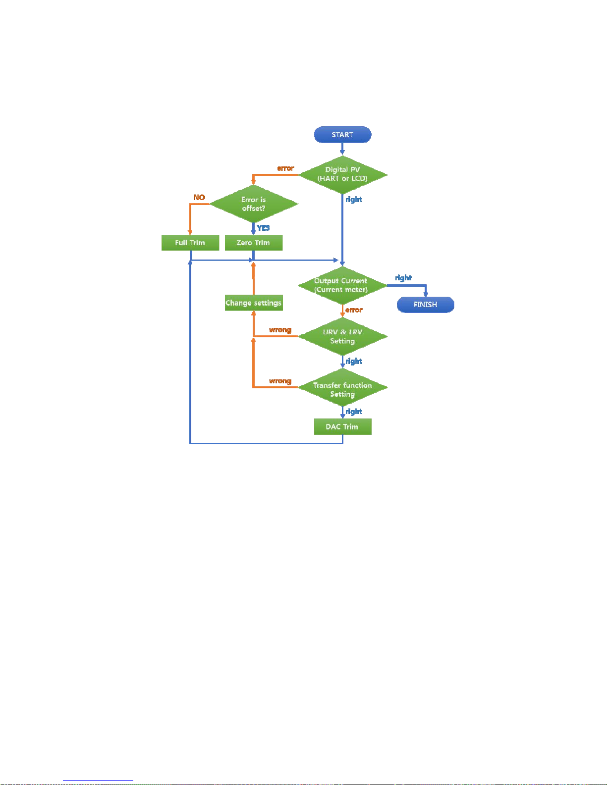
APT3500 Smart Pressure Transmitter Operation Manual M3500-EO1G
56 DUON System Co., Ltd.
Figure 5-3 shows the above Calibration Procedure.
Figure 5-3. Calibration Procedure
5.9.1 Sensor Trim
The Sensor Trim the transmitter sensor input signal convert A/D to lead and how it interprets the
values which it inputs with digital the contents of such interpretation and it is regarding to change
is connected actually in the sensor which in order to correspond.
There are three waysto trim the sensor: Sensor zero trim, full trim and zero adjustment.
Sensor zero trim is a one-point adjustment typically used to compensate for mounting position
effects or zero shifts caused by static pressure.
Two point trim is a full sensor tirm, in which two accurate end-point pressure are applied (equal
to or greater than the range values), and all output is linearized between them. You should
always adjust the low trim value first to establish the correct offset.
Page 59
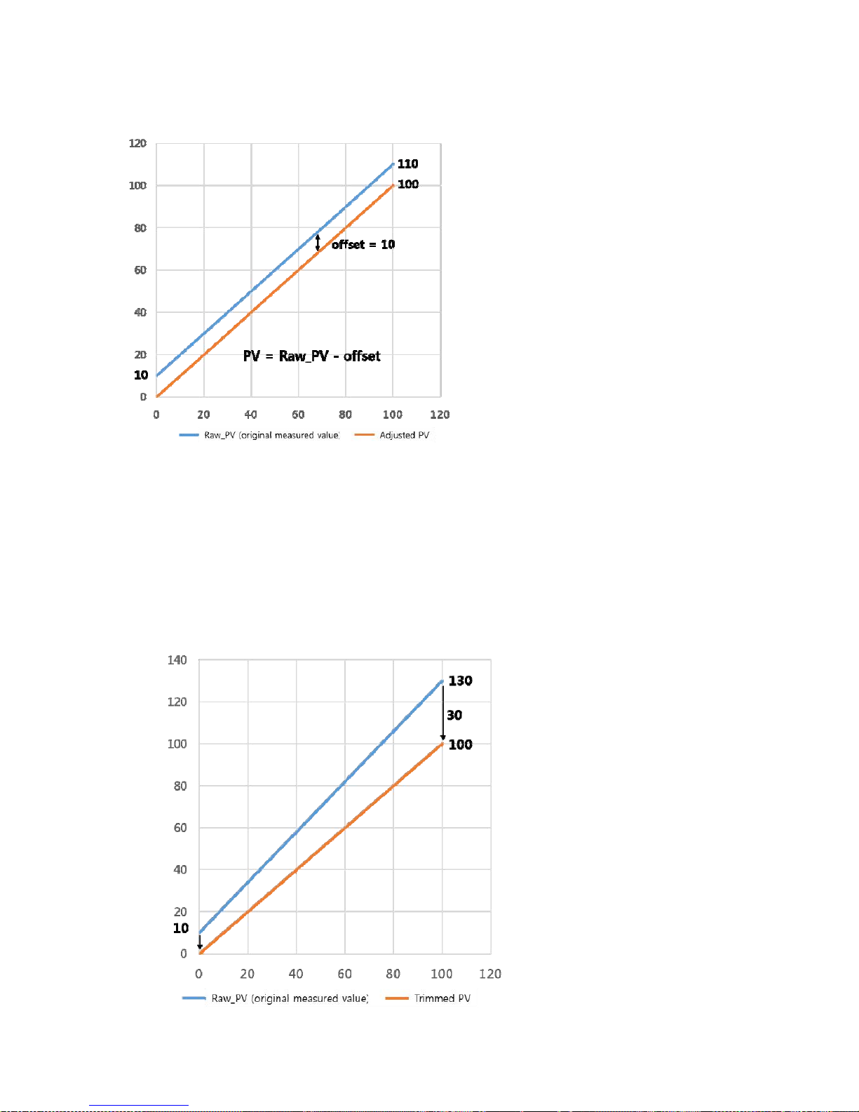
APT3500 Smart Pressure Transmitter Operation Manual M3500-EO1G
57 DUON System Co., Ltd.
Zero Trim and Zero Adjustment are functions
to control offset in the Transmitter
measurement. If a constant error occurs over
the whole region from low pressure to high
pressure as in Figure 5-4, it is possible to
eliminate measurement error by controlling
offset.
In the complete vent mode with no pressure
approval to Transmitter, execution of Zero Trim
can eliminate offset which occurred at the
zero point.
To control the currently measured value to a
certain value without pressure vent, Zero
Adjustment can be executed. In this case,
offset is controlled to move the currently
measured value to desired value. At the time
of Zero Adjustment execution, the currently
approved pressure should be maintained
constantly, and sufficient time should be given for the pressure approved after pressure change
to be stabilized prior to execution. As for Zero offset, set-up value for user and factory initial value
are stored separately, and the factory initial value can always be restored through offset factory
recall function.
As for how to execute Zero Trim and Zero Adjutment making use of button, refer to Chapter 3-7.
As for how to execute Zero Trim and Zero Adjutment making use of HHT, refer to each
corresponding HHT manual or STT30 manual.
A full trim is a two-point sensor
calibration where two end-point
pressures are applied, and all output
is linearized between them. You
should always adjust the low trim
value first to establish the correct
offset. Adjustment of the high trim
value provides a slope correction to
the characterization curve based on
the low trim value. The factory-
established characterization curve is
not changed by this procedure.
The trim values allow you to optimize
performance over your specified
measuring range at the calibration
temperature.
Simply, Zero Trim & Zero
Adjustment give Offset to the
Page 60

APT3500 Smart Pressure Transmitter Operation Manual M3500-EO1G
58 DUON System Co., Ltd.
transmitter and configure them without changing the slope of characterization curve but Full trim
change the slop of characterization curve after configuration.
Step for Full trimming.
(1) Set up stable pressure at 0 % of what user wants to the device during stabilization time, and
then input the low trim value on 0 %.
(2) Set up stable pressure at 100% of what user wants to the device during stabilization time, and
then input the high trim value on 100%.
5.9.2 DA (Digital to Analog) Trim
When the D/A trim convert sensor input signal to 4~20mA output, this ouput value scale
minuteness. Cyclic you recommend to scale analog output for maintain scale.
This function can manage the error about analog conversion if digital value for loop current output.
Page 61

APT3500 Smart Pressure Transmitter Operation Manual M3500-EO1G
59 DUON System Co., Ltd.
Chapter 6 Maintenance
6.1 Overview
This chapter describes breakdown diagnostic and maintenance.
6.2 Safety Message
When operation, it requires specially notice for the safety of operator. Information that raises potential
safety issues is indicated by a warning symbol(▲). Refer to the following safety messages before
performing an operation proceeded by this symbol.
6.2.1 Warning
▲ Warning
Explosion can result in death or serious injury:
◈
Do not remove the transmitter covers in explosion environments when the circuit is alive.
◈Both transmitter covers must be fully engaged to meet explosion-proof requirements
▲ Warning
Electrical shock can result in death or serious injury. If you install high voltage environment or false
condition, power line and lead will be apprered high voltages.
◈Avoid contact with the leads and terminals.
▲ Warning
Electrical can result in death serious injury:
◈ The qualification which is educated only the person whom it prepares will be able to establish the
transmitter.
▲ Warning
Process leak can result in death serious injury:
◈ Before approval pressure install Thermowell or sensor and then close completely. If don't this, it cause
process leak.
◈ when operating, don't take out Thermowell.
Page 62

APT3500 Smart Pressure Transmitter Operation Manual M3500-EO1G
60 DUON System Co., Ltd.
6.3 Hardware Diagnostics
If you suspect a malfunction despite the absence of any diagnostic messages on the HHT follow Table
6-1 described here to verify that transmitter hardware and process connections are in good working
order.
If you suspect a malfunction despite the absence of any diagnostic messages on the HHT follow Table
6-1 described here to verify that transmitter hardware and process connections are in good working
order.
[Table 6-1 Troubleshooting]
Symptom Potential Source Corrective Action
Tra n smit ter
Does not
Communicate
With HART
Communicator
Loop Wiring
Check for a minimum of 250 ohms resistance
between the power supply and HHT.
Check for adequate voltage to the transmitter.
The transmitter always requires 12 ~ 45 Vdc.
Check for intermittent shorts, open circuits, and
multiple grounds.
High Output
Sensor Input Failure
Connect HHT and enter the Transmitter test mode
to isolate a sensor failure.
Loop Wiring
Check for dirty or defective terminals,
interconnecting pins, or receptacles.
Power Supply
Check the output voltage of the power supply at
the transmitter terminals. It should be 12 to 45
Vdc in spite of loop scale.
Electronics Module
Connect HHT and enter the Transmitter test mode
to isolate module failure. Check the sensor limits
to ensure calibration adjustments are within the
sensor range.
Erratic Output
Loop Wiring
Check the output voltage of the power supply at
the transmitter terminals. It should be 12 to 45
Vdc.
Check for intermittent shorts, open circuits, and
multiple grounds.
Check for proper polarity at the signal terminals.
Incase measuring electric current while digital
communication, output appear around +-0.013mA
Electronics Module
Connect HHT and enter the Transmitter test mode
to isolate an electronics mode failure.
Low Output or
No Output
Sensor Element
Connect HHT and enter the Transmitter test mode
to isolate a sensor failure.
Check the PV to see if it is out of range.
Loop Wiring
Check for adequate voltage to the transmitter.
The transmitter always requires 12 ~ 45 Vdc.
Check for intermittent shorts, open circuits, and
multiple grounds.
Check polarity of singal terminal
Check the loop impedence.
Electronics Module
Connect HHT and check the sensor limits to
ensure calibration adjustments are within the
sensor range.
Page 63
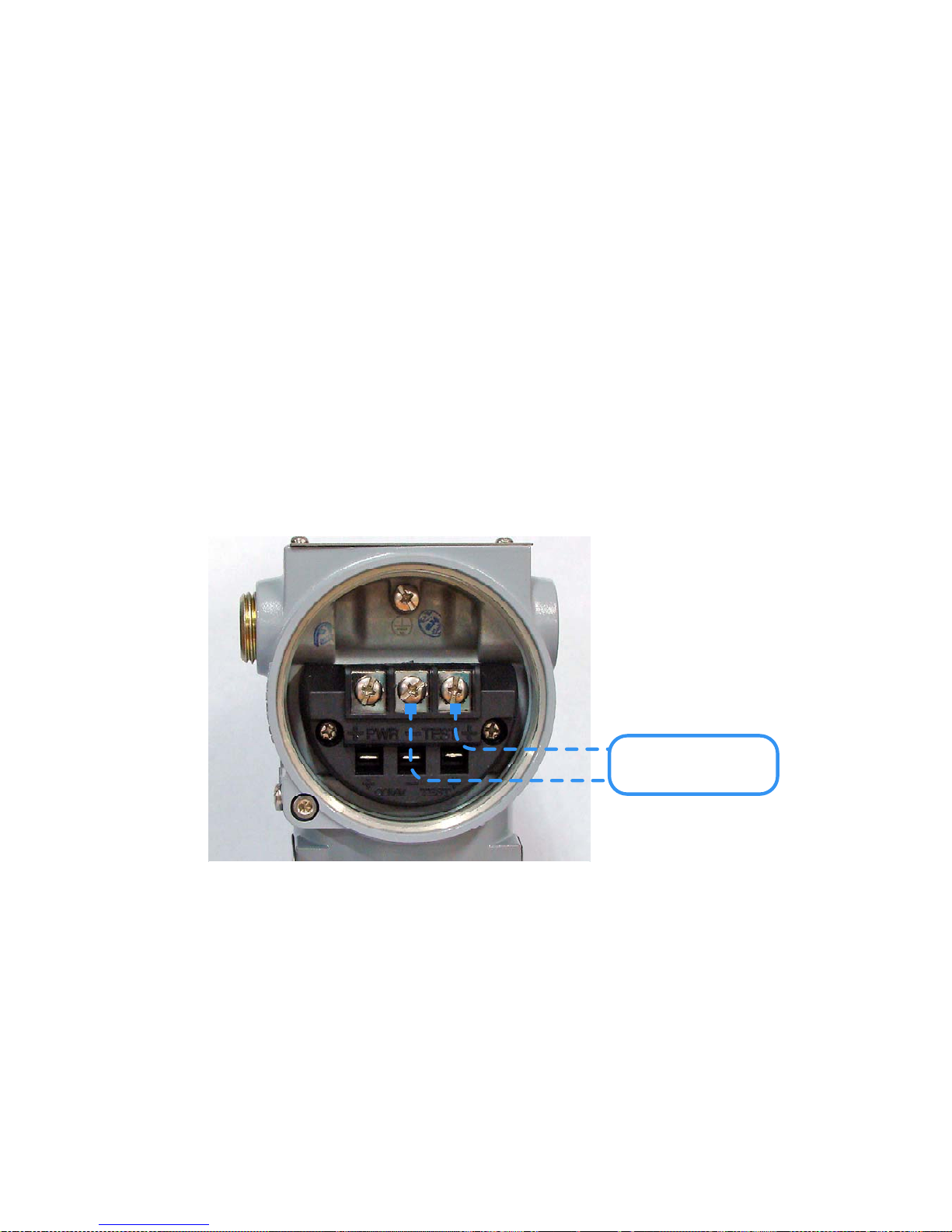
APT3500 Smart Pressure Transmitter Operation Manual M3500-EO1G
61 DUON System Co., Ltd.
6.4 Hardware Maintenance
Autrol APT3500 Smart Transmitters have no moving parts and require a minimum of scheduled
maintenance. Both transmitters feature modular design for easy maintenance. If you suspect a
malfunction, check for an external cause before performing the diagnostics as discussed later in this
section. If you must return failed transmitters or parts, send them to DUON System Co., Ltd. for
inspection, repair, or replacement.
6.4.1 Test Terminals
The test terminal, marked as TEST on the terminal block. The test and negative terminals are
connected to the test terminals; so long as the voltage across the receptacles is kept below the
diode threshold voltage, no current passes through the diode. To ensure that there is no leakage
current through the diode while making a test reading, or while an indicating meter is connected,
the resistance of the test connection or meter should not exceed 10 ohms. A resistance value of
30 ohms will cause an error of approximately 10 percent of reading.
[Figure 6.1 Test Terminals]
Local Indicator
or Current Meter
-
+
Page 64
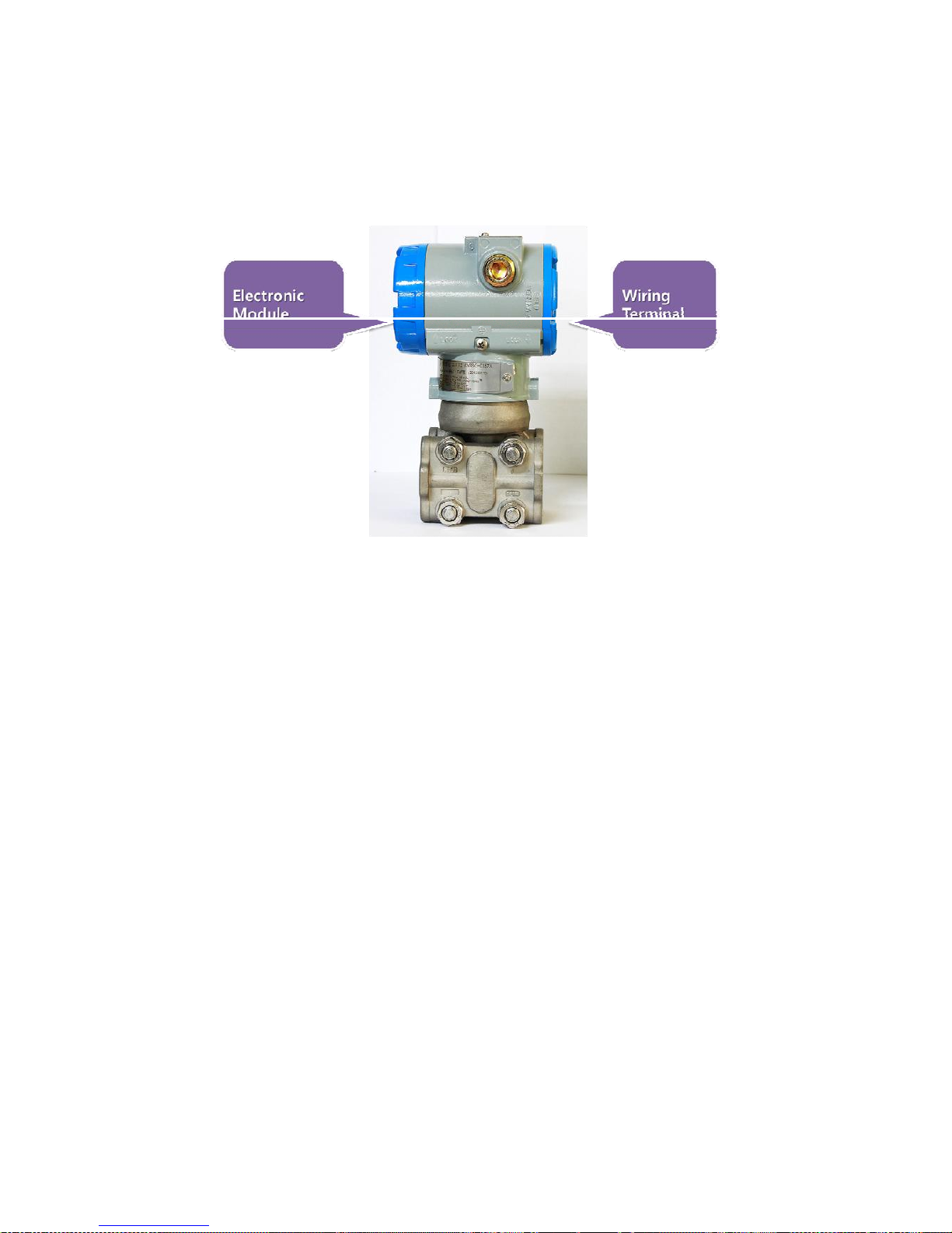
APT3500 Smart Pressure Transmitter Operation Manual M3500-EO1G
62 DUON System Co., Ltd.
6.4.2 Disassembling the Electronics Housing
The transmitter is designed with dual-compartment housing; one contains the electronics module,
and the other contains all wiring terminals and the communication receptacles.
[Figure 6.2 Structure of Housing]
6.4.2.1 Disassembling Electronics Module
Use the following procedure to remove the electronics module.
[Note1]
The electronics are sealed in a moisture-proof plastic enclosure referred to as the electronics
module. The module is a non-repairable unit; if a malfunction occurs the entire unit must be
replaced.
1. Disconnect the power to the transmitter.
2. Remove the cover from the electronics side of the transmitter housing (Figure 6.2). Do not
remove the instrument cover in explosive atmospheres when the circuit is alive. Remove
the LCD meter, if applicable.
3. Remove the two screws that anchor the electronics module to the transmitter housing.
4. Firmly grasp the electronics module and pull it straight out of the housing, taking care not
to damage the interconnecting pins.
[Note2]
The transmitter EEP-Write Jumpers and failure mode are located on the front of the electronics
module. When it will be replaced for a new one, make a same jumper location.
Page 65
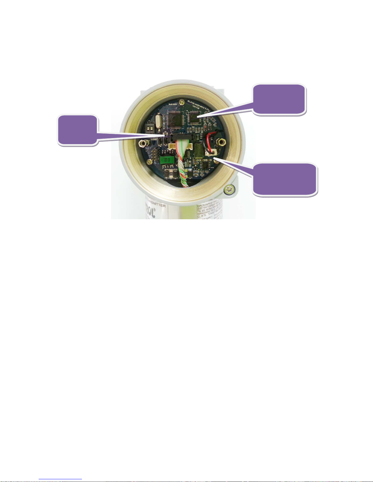
APT3500 Smart Pressure Transmitter Operation Manual M3500-EO1G
63 DUON System Co., Ltd.
6.4.2.2 Fail Mode and Jumper Switch of EEPROM-write
Fail-mode and jumper switch of EEPROM-write is located front of electronics module(Refer to Figure
2-2, 2-3)
6.4.3 Assembling the Electronics Housing
Re-assembling procedure is same as follows.
1. Make sure that Fail-mode and Jumper Switch are set exactly.
2. Insert electronics module in housing
3. Firstly, connect the connector of sensor board with power connector.
Mis connection of the two connectors cause wrong output(4~20mA) and effect on power
of Transmitter.
In case of power connector sandwitched between board and housing, it may cause
wrong output signal and effect on power of transmitter.
4. Fix electronics module with 3 screws.
5. Close the cover of housing..
Figure 6.3 Structure of Electronics Module inner Transmitter
MCU &
Power Module
Analog
Connector
Power(24Vdc)
Connector
Page 66

APT3500 Smart Pressure Transmitter Operation Manual M3500-EO1G
64 DUON System Co., Ltd.
Appendix I
APT3500 SMART PRESSURE TRANSMITTER
Message Description Remarks
ADJ-U Out of Zero setting value when Zero Adj function using button(Upper
side)
ADJ-L Out of Zero setting value when Zero Adj function using
button(Lower side)
ZERO Initial message in using Zero button
SPAN Initial message in using Span button
BT-ERR Button input Sequence error
P-LOCK Button input error when Protect Locked
ZT-ERR Setting Limit (10%) Error when Zero Trim
-TR- Zero Trim Done
ZR-ERR Setting Limit error when executing Zero button function
SP-ERR Setting Limit error when executing Span button function
-ZR- Zero button function done
-SP- Span button function done
-ZA- Zero Adjustment done
-DONE- Setting Done using button
R-OVER Setting Limit error when executing other setting function
LCD_OV Over figure values for LCD
SCD-ER Sensor Code Error
F-RST Flash Setting Data Reset
F-LOCK While Flash Setting Data Reset, Protect Locked
F-FAIL Flash Setting Data Reset Failure
-FR- Flash Reset Done
A-RST Analog EEPROM Initializing Start
A-STOR Analog EEPROM Whole Write
A-FAIL Analog EEPROM Whole Write Failure
Page 67

APT3500 Smart Pressure Transmitter Operation Manual M3500-EO1G
65 DUON System Co., Ltd.
LCD DISPLAY COD
Message Description Remarks
-AC- Analog EEPROM Whole Write Done
S-FL Sensor Fail
S-OP Sensor Overpressure
AEP-RF Analog EEPROM read checksum error
TS-FL Temperature Sensor Error
AEP-WF Analog EEPROM write fail
EOSC Crystal Element Defect Alarm
FAVE Flash Access Violation
PGM-ER Program Memory CRC error
PASSER Wrong password input
TOO-H Input number is too large
TOO-L Input number is too small
LCD_OV The number to be displayed on LCD exceeds the display range
Page 68

APT3500 Smart Pressure Transmitter Operation Manual M3500-EO1G
66 DUON System Co., Ltd.
APPENDIX II
PRODUCT CERTIFICATIONS
This Chapter describes flame-proof certification of APT3500 series.
1. Certification Company
Company Name: DUON SYSTEM CO., LTD.
(AUTROL
○
R
)
Region : 232, Beotkkot-ro, Geumcheon-gu, Seoul , Korea 153-801
2. KOREA (KOSHA) Flameproof
Certificate Number : 12-AV2BO-0741
Ex d IIC T6, IP67 (-20℃ ≤ T
amb
≤ +60℃)
V
dc
= 12.5 ~ 45Vdc, 4~20mA, Process Temperature: Below +80℃
a. KOREA (KOSHA) Flameproof Standards
Notification of Protection Device Duty of Safety Certification (Ministry of Employment & Labor
Notification No. 2010-36)
3. ATEX Explosion-proof Certification
Certificate Number : xxxxxxxxxxxxxxxxx
Certificate Range : Ex d IIC T6...T4, IP67
V
dc
= 12.5 ~ 45Vdc, 4~20mA
4. Pending from FM Explosion-proof Certifier
Page 69
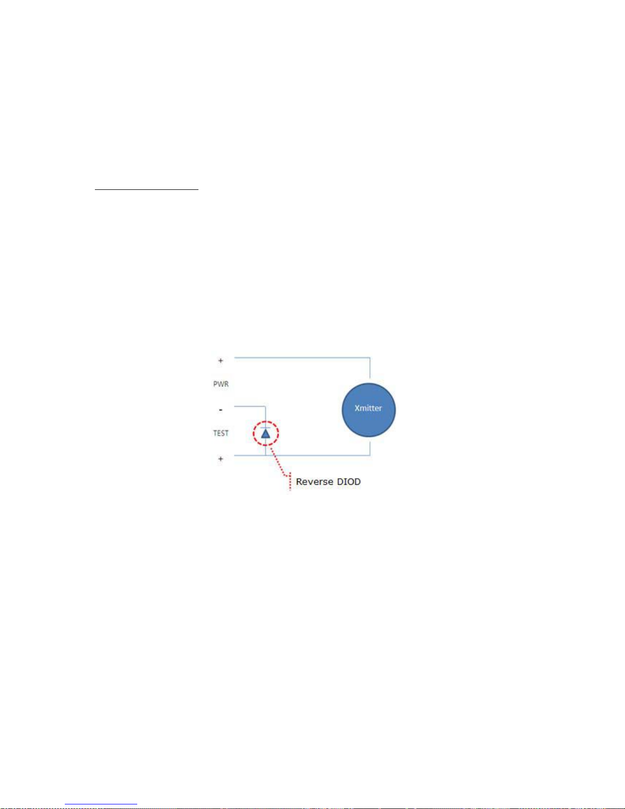
APT3500 Smart Pressure Transmitter Operation Manual M3500-EO1G
67 DUON System Co., Ltd.
APPENDIX III
Special Condition for Safe Use
INSTALLATION
ATEX
◈ Line connection method and length should be suitable for the corresponding
flameproof specification.
◈ Power approved to Transmitter should not exceed rating.
◈ To avoid problems that may occur in power connection to Transmitter, the
backward diode was used. However, in the event of power connection to
wrong place, the backward diode may lose its function.
[Connection of backward diode]
◈ Parts connected to Transmitter additionally should definitely obtain
authorization on regional classification and gas classification.
◈ Cable entrance device should obtain certification for pressure-resistance and
flameproof, and be suitable for working condition.
◈ Unused wire connection should be blocked properly with plugs.
◇ Housing ground should always follow “Local Electrical Codes”. The most
efficient grounding is direct connection to earth with minimal impedance.
Page 70

APT3500 Smart Pressure Transmitter Operation Manual M3500-EO1G
68 DUON System Co., Ltd.
◇ Housing grounding method
● Internal Ground Connection: Internal grounding screw is located at
terminal of the housing interior, and the screw is identified by the ground
symbol.
● External Ground Assembly: It is located at the right side of the housing
front (facing LCD), and identified by ground symbol.
◇ When impulse line is used, Stopping Boxes should be directly connected to
the housing wall.
◇ Cable grand should obtain proper environment certification for flameproof to
be used at ZONE 1.
◇ Impule line should engage at least five screw thread.
◇ Sensor should engage at least seven screw thread, and is prevented from
rotating by tightening “Housing rotation” screw.
 Loading...