

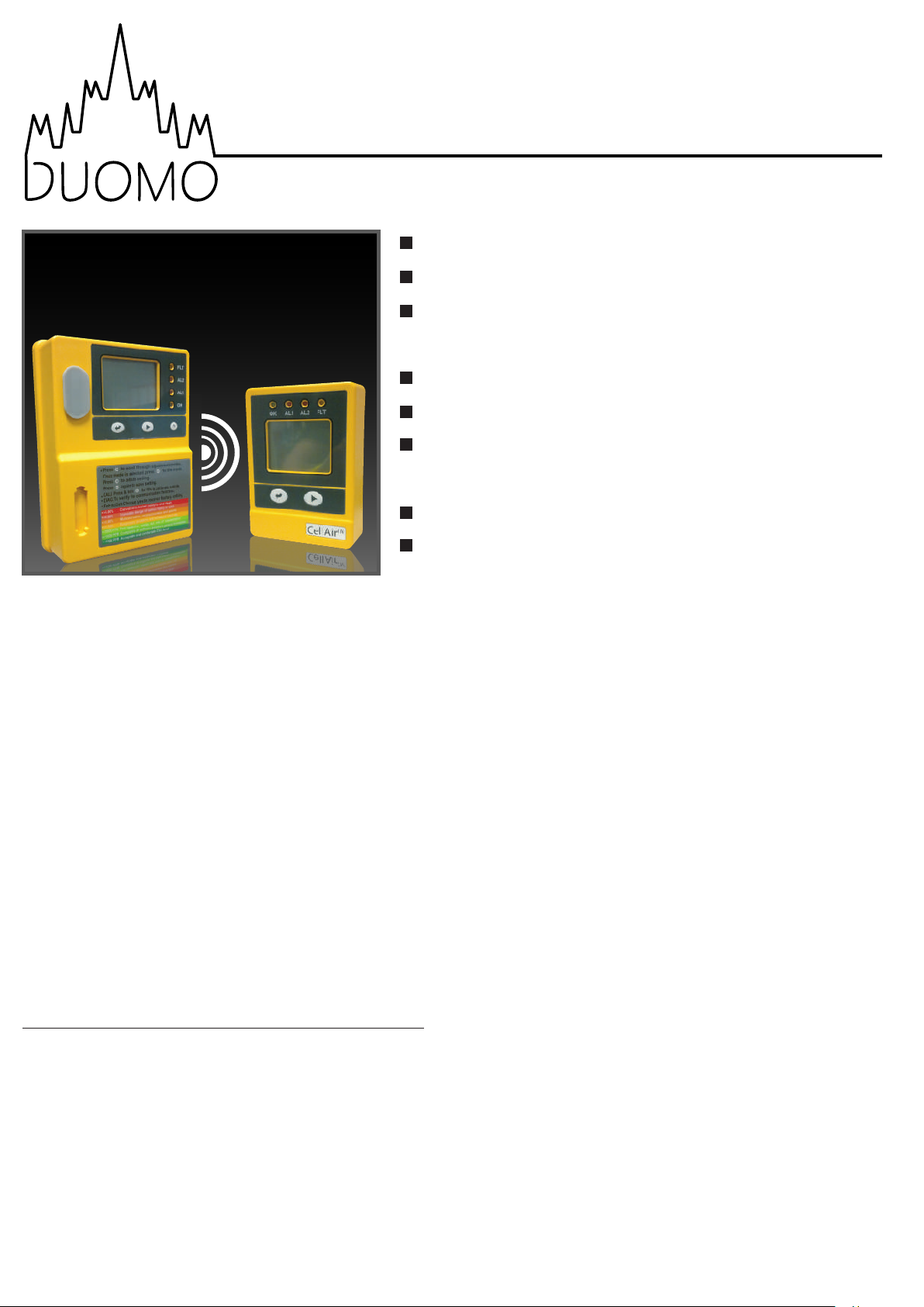
CellAirTM CO2 Detector
NDIR (Non-Dispersive Infrared) sensor
Measures up to 50,000ppm
Can handle up to 3 remote display units;
1 up to 25m away, 3 up to 8m apart
Large LCD display indicates ambient
CO2 concentration and temperature
Relay output to automatically control
a fan to ventilate confined spaces
Audible and visual alarm indications
IP54 water proof protection
Application
Thankyou for selecting the Duomo CellAirTM CO2
monitor. It is designed to detect the presence of
carbon dioxide in the ambient air to protect people
in confined spaces. High concentrations of CO
confined spaces are dangerous, and may lead to
health problems ranging from headaches and
fatigue to asphyxiation and death. CellAir
audible alarm and visual indication which will
activate when CO
level. Detection of high levels of CO
activate a relay that could be used for a fan to
ventilate the confined space and reduce CO
concentration in the area. CellAir
used in CO
cellars, beverage dispensing areas and fast food
outlets.
2
concentration reaches a pre-set
2
TM
can be widely
storage areas, breweries, wineries,
TM
will also
2
in
2
has an
Package Contents
SEU (Sensor Unit), RDU (Remote Display Unit), panel
holders, network cable connector, communication
cable (8m length), fixtures and fittings, user manual.
Specifications
CO2 Specification
Measurement range - 0 - 50,000ppm
Accuracy - ±100ppm or ±5% of reading
Temperature Specification
Measurement range - 0oC - 50oC (32oF - 122oF)
Alarm Levels
Alarm 1 - 0.5 / 1 / 1.5 / 2%
Alarm 2 - 1.5 / 2 / 2.5 / 3 / 3.5 / 4%
Operating Conditions
Operating temperature - 0oC - 40oC (32oF - 104oF)
Humidity range - 0 ~ 95%RH
2
Storage Conditions
Storage temperature - -20oC - 60oC (-4oF - 140oF)
Power Supply & Relay Output
AC adapter - 110/220 VAC
AC input - 100 ~ 240 VAC, 50/60Hz
AC output - 6 VDC, 1.8 W
Relay output - 30 VDC or 250 VAC, max. 2A, SPST, NO
Accuracy
Annual drift < 20ppm / year @ 400ppm
Calibration
User calibration via onboard menu system
Recommended calibration interval - 2 years
w: www.duomo.co.uk - e: sales@duomo.co.uk - t: 01905 797989 - f: 01905 774296 | © Duomo (UK) Ltd. 2016

SEU (Sensor Unit) Function Instruction
The SEU should be placed in a room where the CO2 is likely to accumulate such as a room where CO2 is stored,
like an area with CO
The SEU has several functions. These are;
"DIAG" - Performs a communication test between the SEU and RDU.
"CALI" - Calibrates the unit to the ambient air.
"ReFactSet" - Restores the unit to its factory default settings.
"AL1"- Sets the 1st alarm level to 0.5, 1, 1.5 or 2% CO2 concentration (default is 1.5%).
"AL2" - Sets the 2nd alarm level to 1.5, 2, 2.5, 3, 3.5 or 4% CO2 concentration (default is 3%).
When CO2 concentration exceeds the first alarm level, the red AL1 LED will blink and the alarm will sound
intermittently. At this stage, the relay will be actuated. When levels drop back below the alarm level, the LED will
stop blinking and the alarm will stop sounding.
beverages. The large LCD displays the ambient CO2 concentration and the temperature.
2
When concentrations exceed the second alarm level, both AL1 and AL2 LED's will flash and the alarm will sound
more quickly. The alarm will remain in this state until the button has been pressed.
In the case of very high concentrations, 'ESC' will appear on the screen of the unit. It is imperative that the area be
completely ventilated and that no one enters the area until concentrations have dropped. To reset the unit, use
the "ReFactSet" function.
RDU (Remote Display Unit) Function Instruction
The RDU (Remote Display Unit) should be placed outside the room which is being monitored. This unit is
connected to the SEU by the communication cable provided. It should be placed where it can be conveniently
seen before entering the room where the SEU is located. The RDU is a repeater and displays the measurements
made by the SEU on an LCD. The RDU can be placed a maximum of 24 metres (78.7 feet) away from the SEU.
The RDU also has the "DIAG" function to test the comms between the SEU and the RDU.
Safety Notes
Warning: To ensure this product is used correctly and safely, please read these warnings and the entire user
manual before use.
Please handle the device carefully; do not subject the product to impact or shock.
1.
Do not place the unit, or the adaptor, near a heat source.
2.
Do not touch the exposed electronic circuitry of the device under any circumstances.
3.
Please only use the included power adaptor.
4.
Make sure that the power adaptor is mounted using the plug lock so that it cannot be removed without the
5.
use of tools.
DO NOT enter the room when "ESC" is displayed on the LCD of the SEU or RDU. Some action must be taken
6.
before entering the room where the SEU is installed.
Maintenance
We recommend that users test the communication between the SEU and RDU using the "DIAG" function
periodically. If the four LED's flash and the alarm sounds on both units then the system is functioning normally.
w: www.duomo.co.uk - e: sales@duomo.co.uk - t: 01905 797989 - f: 01905 774296 | © Duomo (UK) Ltd. 2016

Fault Codes & Troubleshooting Guide
LCD Fault
Icon
Er3
Er4
Er5
Er6
Er7
Description
The ambient temperature has
exceeded the temperature
range (0
There is an incorrect
measurement or the sensor
has exceeded its lifespan
System problem
Internal data transmission
o
C - 50oC)
EEPROM
error
SEU
Indication
"Er3" flashes,
Fault LED
flashes, Alarm
sounds
"Er4" flashes,
Fault LED
flashes, Alarm
sounds
"Er5" & "Er6"
flash, Fault LED
flashes, Alarm
sounds
"Er7" flashes,
Fault LED
flashes, Alarm
sounds
RDU
Indication
"Er3" flashes,
Fault LED
flashes, Alarm
sounds
"Er4" flashes,
Fault LED
flashes, Alarm
sounds
"Er7" flashes,
Fault LED
flashes, Alarm
sounds
"Er7" flashes,
Fault LED
flashes, Alarm
sounds
Suggested Action
This error will disappear when
the temperature returns to
within the acceptable range
Power the unit down, then back
up. If "Er4" still appears, please
return the unit to the dealer
Power the unit down, then back
up. If "Er5" & "Er6" still appears,
please return the unit to the
dealer
Power the unit down, then
back up. Check the
communication cable
between the SEU and RDU
The accuracy of the CO
Er8
sensor may deviate from the
actual CO
concentration
2
LCD Display Symbols
PP
M
CO2
c
Temperature (Celcius or Fahrenheit) Ambient temperature
DIAG
AL1
2
CO2 concentration (ppm) Ambient CO2 concentration
Diagnostic check
"Er8" flashes,
Fault LED
flashes, Alarm
sounds
MeaningSymbol Description
Alarm The unit is in alarm
First alarm
level
"Er8" flashes,
Fault LED
flashes, Alarm
sounds
The communications between the
SEU and RDU are being checked
first alarm level. The relay has been
Power the unit down, then back
up. If "Er8" still appears, please
return the unit to the dealer
CO2 concentration exceeds the
activated
AL2
CALI
ReFactSet
w: www.duomo.co.uk - e: sales@duomo.co.uk - t: 01905 797989 - f: 01905 774296 | © Duomo (UK) Ltd. 2016
Second alarm
level
Calibration
Restore factory setting
Escape
High concentration
CO2 concentration exceeds the
second alarm level. DO NOT
ENTER THE ROOM.
Calibrates the CO2 sensor based on
ambient CO
Recovers factory default settings
The CO2 level is above the second alarm
level. Action must be taken.
The CO2 concentration is above 5%
concentration
2

Customising Settings
There are several settings on the CellAirTM that can be altered to personalise it for your application.
Temperature oC/oF
PP
M
CO2
c
PP
M
CO2
F
1. Press the button to switch between oC and oF
Using the "DIAG" function
PP
M
CO2
c
DIAG DIAG
PP
M
CO2
c
1. Press the button until "DIAG" flashes
2. Press , the four LED's on the SEU will flash and
its alarm will sound
3. The four LED's on the RDU will flash and its alarm
will sound
Using the "CALI" function
Setting the first alarm parameter
PP
M
CO2
c
AL1 AL1
%
PP
M
CO2
c
1. Press button until "AL1" flashes
2. Press , the "AL1" icon shown on the LCD
3. Press to go through the parameters
4. Press again to save the setting
Setting the second alarm parameter
PP
M
CO2
c
AL2 AL2
%
PP
M
CO2
c
1. Press button until "AL2" flashes
2. Press , the "AL2" icon shown on the LCD
3. Press to go through the parameters
4. Press again to save the setting
PP
M
CO2
CALI CALI
c
PP
M
CO2
c
the first alarm level.
Using the "ReFactSet" function
Note: The second alarm level should be higher than
Press button until "CALI" flashes
1.
Press , the "CALI" icon shown on the LCD
2.
Press and hold for at least 10 seconds. The "CALI"
3.
icon will flash and the unit will calibrate
automatically. After 10 minutes the LCD will
display "Pass" or "Fail". If "Fail" appears please try
calibrating the unit again.
Note: If possible, calibrate the SEU outside in ambient
air. Wait 10 minutes for the unit to stabilise before
calibrating. DO NOT breathe on or near the unit during
calibration.
ReFactSet ReFactSet ReFactSet
1. Press button until "ReFactSet" flashes
2. Press , then to select either "Yes" or "No"
3. Press again to save the setting
Only use this function if you wish to return the sensor
to its factory default settings, or if the unit displays
"ESC" on the LCD under conditions of very high
concentrations.
PP
M
CO2
c
CO2
c
Installation Instructions
Choose a suitable location to install the SEU. Fix the panel holder on the wall at the recommended height of
1.
about 0.45m (1.5 feet) from the floor and as close to the manifolds and valves as possible.
Put the SEU on the panel holder, making sure the connection is tight.
2.
Fix another panel holder in a suitable location outside the monitored space. Push the RDU onto the panel
3.
holder and stick the warning paper next to the RDU.
The communication cable is pre-wired to the SEU. Route this through to the RDU and plug it into the input
4.
port. Communication between the two units is now established.
The CellAirTM has one relay output which is pre-wired to the SEU. The relay can be used to operate an external
5.
alarm system or ventilation system. It will be triggered when the CO
level.
After completing the installation, remove the rubber cap from the gas entry point, power the unit up and use
6.
the "DIAG" function to verify the connection between the SEU and the RDU.
concentration exceeds the first alarm
2
CO2
c
w: www.duomo.co.uk - e: sales@duomo.co.uk - t: 01905 797989 - f: 01905 774296 | © Duomo (UK) Ltd. 2007

Installation
The diagram below details a typical installation scenario of the CellAirTM unit. For advice on where and how to
install this unit please contact Duomo (UK) Ltd. on 01905 797989.
Fan for
ventilation
Power
Power
supply
supply
for fan
Press to scroll through adjustment modes,
Once mode is selected,press to this mode.
Press to adjust setting.
Press to again to save setting
CALI:Press&hold for 10s to calibrate outside.
DIAG:To verify the communication function.
ReFactSet:Choose yes to recover factory setting.
>5.00%
>4.00%
>3.00%
>1.50%
>5000PPM
>1000PPM
<1000PPM
Layout & Dimensions
A
M
G
H
L
FLT
AL2
AL1
OK
IJK
SEU (Sensor unit)
Convulsions,instant paralysis and death
Immediate danger of serious injury or death
Muscular pains,unconsciousness and spasms
Respiratory problems and increased heart rate
Feel headache,sleepy,dull,loss of concentration
Complaints of stiffness and odors,general drowsiness
Acceptable and comfortable CO2 level
A. LCD display
B
B. FLT LED (Fault indication)
C
C. AL1 LED (Alarm 1)
D
E
D. AL2 LED (Alarm 2)
E. OK LED (Power indication)
F
F. Reset button
G. Mode button
H. Enter button
I. Communication cable
to RDU
J. Relay output
K. Power supply
L. Rubber cap
M. Gas entry
RDU Repeater
Press to scroll through adjustment modes,
Once mode is selected,press to this mode.
Press to adjust setting.
Press to again to save setting
CALI:Press&hold for 10s to calibrate outside.
DIAG:To verify the communication function.
ReFactSet:Choose yes to recover factory setting.
Convulsions,instant paralysis and death
>5.00%
Immediate danger of serious injury or death
>4.00%
Muscular pains,unconsciousness and spasms
>3.00%
Respiratory problems and increased heart rate
>1.50%
Feel headache,sleepy,dull,loss of concentration
>5000PPM
>1000PPM
Complaints of stiffness and odors,general drowsiness
<1000PPM
Acceptable and comfortable CO2 level
46.6mm124.8mm
167.7mm
Q RPO
O. OK LED (Power indication)
33.4mm85mm
P. AL1 LED (Alarm 1)
OK AL1 AL2 FLT
S
Q. AL2 LED (Alarm 2)
R. FLT LED (Fault indication)
S. LCD display
T. Enter button
T U
U. Mode button
117.5mm
V. RJ45 plug for SEU (Input)
W. RJ45 plug for next RDU
Input
Output
Input
Output
(Output)
WV
w: www.duomo.co.uk - e: sales@duomo.co.uk - t: 01905 797989 - f: 01905 774296 | © Duomo (UK) Ltd. 2016
 Loading...