

Page 1
DuoGen-3 Water / Wind
Battery Charger
USER’S MANUAL
Page 2
The Physics of Wind Generation
The power output from any wind turbine is largely dependent on two
factors, the prevailing wind speed and the swept area of the rotor.
This intercept area is governed by the length of the air blades - the
longer they are, the greater the potential power of the wind generator.
Unfortunately, it is not practical to fit large wind turbines on yachts, and
machines with rotor diameters of around 1 metre are the norm.
The amount of energy available in a wind stream varies as the cube of
its velocity - for example, there is over 70% more energy available at
12 mph than at 10 mph. Very low wind speeds contain very little energy,
so although a wind turbine may spin, it will produce little or no power.
With increasing wind speed output from the turbine rises exponentially.
Wind is a variable but occasionally very powerful resource, and sensible
sailors tend to avoid its worst excesses. Where possible, sailors will sail
downwind and anchor in sheltered spots, all of which reduces the energy
available to a yacht-mounted wind generator.
Given these constraints, a wind generator is unlikely to keep pace with
all electricity usage on a daily basis. It can, however, make a very useful
contribution to the energy budget.
Please note: some of the
illustrations in this manual
are of the original DuoGen
model, but the instructions
apply to both DuoGen
versions 2 & 3.
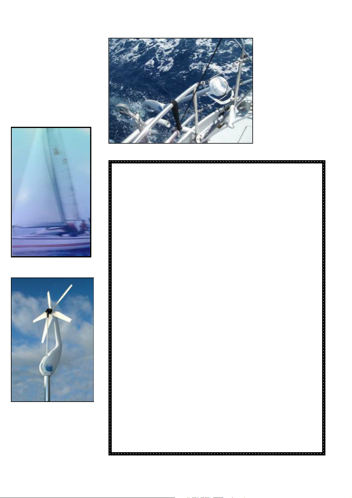
The DuoGen is different.
By deploying the water mode when you go cruising:
The DuoGen taps into the wind power that the yacht’s whole sail area
intercepts
This is many times greater than that of a yacht-sized turbine
At typical cruising speeds, the DuoGen in water mode produces
enough power to run most if not all of the yacht’s electrics
The DuoGen’s water mode is much more efficient than a wind
generator at sea
and much easier to live with.
1
Page 3
Welcome to DuoGen
Welcome to DuoGen
Welcome to DuoGenWelcome to DuoGen
CONTENTS
CONTENTS
CONTENTSCONTENTS
Congratulations on your purchase of the DuoGen water/wind
battery charging system for yachts.
DuoGen has been especially designed and precision
manufactured to provide the most practical and user-friendly
system currently available for renewable energy electricity
generation on cruising yachts.
DuoGen is a combined water and wind generator that can be easily
reconfigured to harness the kinetic energy in either a wind stream or
a water stream in order to produce electricity. DuoGen has been
specifically designed for use aboard cruising yachts where the wind
mode is operated in harbour or at anchor, and the water mode is
deployed when the yacht is under way or at anchor in flowing water.
The benefit of this dual mode system is that the owner has greater
potential for energy conversion than is possible with a single source
system. This is because the air stream intercepted by a yacht’s sails
when it is under way is many times the area intercepted by a typical
wind turbine. In a given wind speed, therefore, the amount of battery
charging power produced is usually far greater when a yacht is under
sail and a water generator is deployed.
1 The physics of Wind Generation
2 Welcome to DuoGen
3 Mounting Options
3 Installing DuoGen
4 DuoGen in wind mode
4 Wind mode outputs
5 Duogen in water mode
5 Water mode outputs
5 Adjusting the diving plane
5 Drag performance comparison
6/7 Electrical Connection with circuit
diagrams
6 Using a battery monitor
8/9/10 Deploying DuoGen in wind
mode
9 The upper tower clamp
11 Self furling
12/13/
Deploying DuoGen in water
14/15
mode
16 Maintenance and repairs
16 Spare parts list
16 Contact details
17 Regulation
DuoGen brings the benefits of dual mode operation to the yacht
owner in a truly practical form. The change from water to wind mode
is accomplished in seconds without the use of tools and without
having to demount and reposition major system elements or electrical
connections.
When using your DuoGen, always exercise due care and operate the
equipment in accordance with the manufacturer’s
recommendations contained in this manual. DuoGen should then
deliver years of trouble free service.
This instruction manual contains important safety
information which will enable you to get the most from
your DuoGen. Please read this manual thoroughly prior
to the installation and operation of the equipment.
18 Commissioning
19 Performance and Expectations
20 Guarantee
20 Certificate of conformity
20 Your notes
21/22/
Appendix, / Universal mount
23/24
bracket installation
2
Page 4
Installing DuoGen
Installing DuoGen
Installing DuoGenInstalling DuoGen
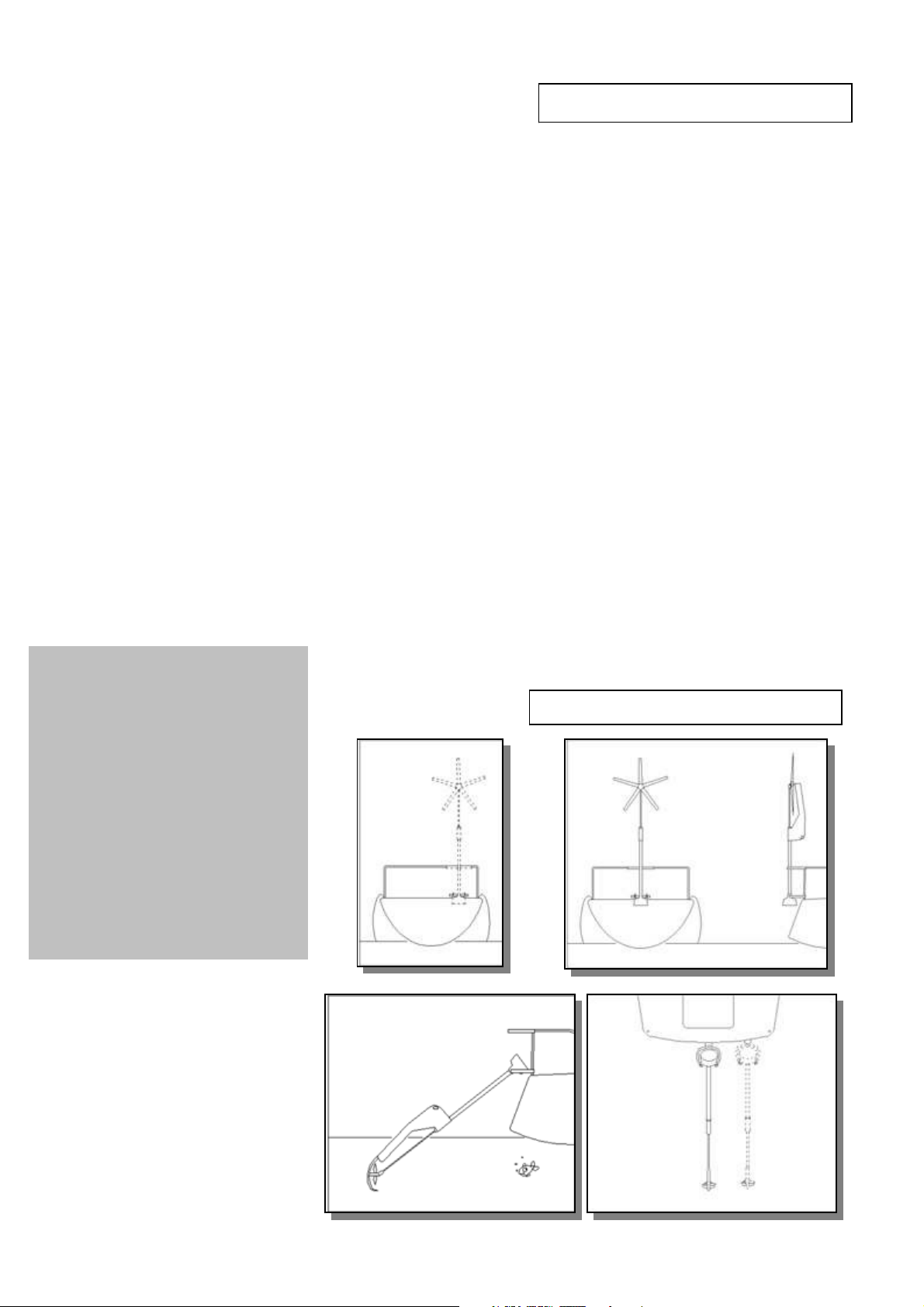
The DuoGen is supplied complete with a universal mount kit. This hardware has been
designed to offer flexibility of mount options. In most cases, the universal mount bracket is
simply clamped to the existing pushpit rail and the swivel foot at the bracket’s base is
through-bolted to the coaming or transom. Once in place, the universal bracket provides
the upper and lower mount points for the DuoGen.
Of course, yachts vary widely in size and form. In some cases, such as canoe stern yachts
or yachts with extended bathing platforms, some additional bracketry may be required.
Eclectic Energy has lots of experience of installing DuoGens, and can offer offer advice
and suggestions for achieving the best installation - a photograph or drawing with some
key dimensions such as freeboard and rail height & diameter will help us advise you.
The DuoGen should be placed either on or as close to the yacht’s centre line as possible.
This minimises the effects of heeling on the running depth of the water mode. However, in
practice, if the mounting is within 800 - 900 mm of the yacht’s centre line, the DuoGen will
perform well.
Once the DuoGen has been installed all subsequent operations and mode changes are
accomplished without the need for tools.
For information on achieving an optimal mounting on your yacht, refer to the dimensioned
mounting schematic provided in your Manual pack.
Universal mount bracket installation instructions are included in the appendix at the end of
this manual.
DuoGen is supplied complete with
standard mount hardware. In most
cases,this is sufficient to achieve
an excellent installation.
Other items you may require
include:
Regulator with dump load
Waterproof deck gland
Spares pack
Battery monitor or ammeter
etc
Recommended spare parts
are listed on Page 16
Mounting Options
Mounting Options
Mounting OptionsMounting Options
3
Page 5
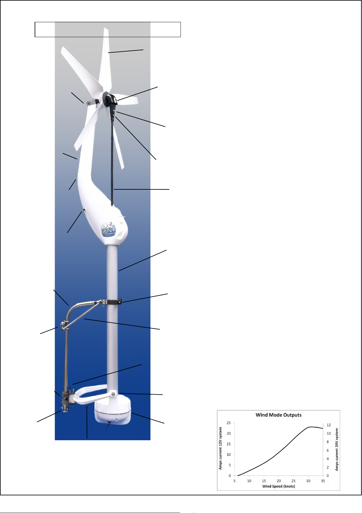
DuoGen in Wind Mode
Air blade (10028)
Air hub, contains
Mortice pin
(80022)
Yaw arm
(90033)
sealed bearings
Conical connector
gear set and
(90044)
Drop-nose
pin, secures
drive shaft
(80023)
(80132)
The DuoGen has been carefully
designed to be as safe as
possible in operation. However,
all rotating machinery is
potentially hazardous.
In consequence, the equipment
should be operated in
accordance with the
manufacturer's instructions
at all times.
!
Recovery
lanyard
shackle
(10320)
Yaw arm
release
plunger
(90124)
Universal
mount tube
(10110)
Rail
clamp
(10124)
Drive shaft
(short: 90030
long: 90031
extra long: 90032
inner section only: 90083)
Tower with top
bearing
(short: 90053
long: 90054
extra long: 90055)
Upper tower
clamp 3 inch
(90106)
Strut assembly
(short: 90011
long: 90012
extra long: 90017)
C-bracket lock
screw set (80034)
C-bracket
assembly
Universal
swivel foot
(90051)
(80144)
Alternator mount
pins (90016)
Alternator
(12 V: 90025
24 V: 90026)
Alternator
yoke (90085)
All performance figures are indicative. Actual outputs may vary. E&OE
4
Page 6

DuoGen in Water Mode
Adjusting the diving plane
The angle of attack of the DuoGen’s diving plane is adjustable by a few degrees either side of 0º or
hydrodynamic neutral.
The neutral point is found by aligning the mark on the diving plane and water impeller bracket.
0º should prove suitable in most cases.
Adjusting the diving plane in the minus
direction will cause the impeller to run nearer the surface and adjusting in the positive direction will cause it to run
deeper.
To adjust, slacken the M8 pivot bolt,
and loosen the socket cap lock screw below it. Re-position the diving plane and re-tighten the M8 pivot bolt.
Finally, re-tighten the socket cap screw to lock the diving plane securely in the new position.
Ensure that the bolt and lock nut are tightened firmly.
The DuoGen's water
mode is generally benign
in operation, but care
should be taken when
deploying the unit that no
swimmers or other
obstructions are in the
water beneath it.
!
Water bracket
(10310B)
Yaw arm
lock hole
Water drive bearings
& pin transmission
Water impeller
(10058B)
Diving plane
(10325B)
(90115)
Drag: DuoGen’s water mode
operates in the top 1/2 metre of
water, within the same wave as the
yacht. Amp for amp,drag from the
impeller unit is 30 % lower than that
of other towed units.
All performance figures are indicative. Actual outputs may vary. E&OE
5
Page 7
Electrical Connections
Electrical Connections
Electrical ConnectionsElectrical Connections
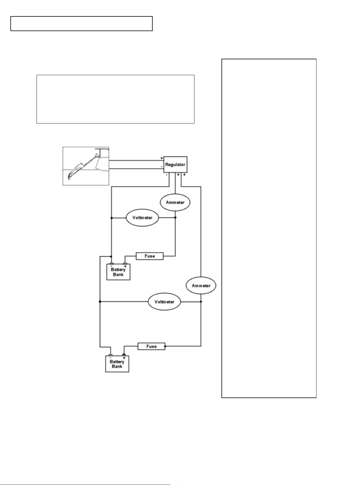
Wiring diagram showing twin battery bank system with
charge splitting regulator and independent metering.
Connect the output cable to the battery bank(s) using
the suggested wiring diagrams for guidance.
Remember to observe the correct polarity.
RED to POSITIVE + and BLACK to NEGATIVE –
The DuoGen alternator is
fitted with 2 metres of 4.5
sq. mm. cable.
Use cable of at least this
cross -section to connect
from the lazarette area to
the batteries.
An in-line fuse is supplied, rated at 40
amps for a 12 volt machine and 20
amps for a 24 volt machine.
It is important that a fuse is fitted
close to each battery bank.
Where a battery monitor is
fitted
If your yacht is fitted with a
digital battery monitor, it will be
driven from a shunt installed
close to the batteries. Shunts
are typically about 100 mm long,
consisting of a brass bar with a
terminal post at each end.
One side of the shunt is
connected directly to the battery
terminal. All other connections
are made to the opposite side of
the shunt, which may be
connected to a busbar.
The shunt is most usually
connected in the negative line.
When wiring the DuoGen to a
system fitted with a shunt,
observe polarity and connect the
appropriate DuoGen output
cable to the non-battery side of
the shunt.
Again observing polarity, the
other DuoGen output cable
should be made directly to the
battery terminal or associated
busbar.
The DuoGen’s output will now
pass through the shunt and the
monitor will display a reading.
If the shunt is bypassed by
connecting both positive and
negative output leads directly to
the battery, the meter will fail to
‘see’ the DuoGen, and register
no output.
Note that where a battery
regulator is fitted, dumped
energy from the DuoGen will not
be seen by the battery monitor.
6
Page 8
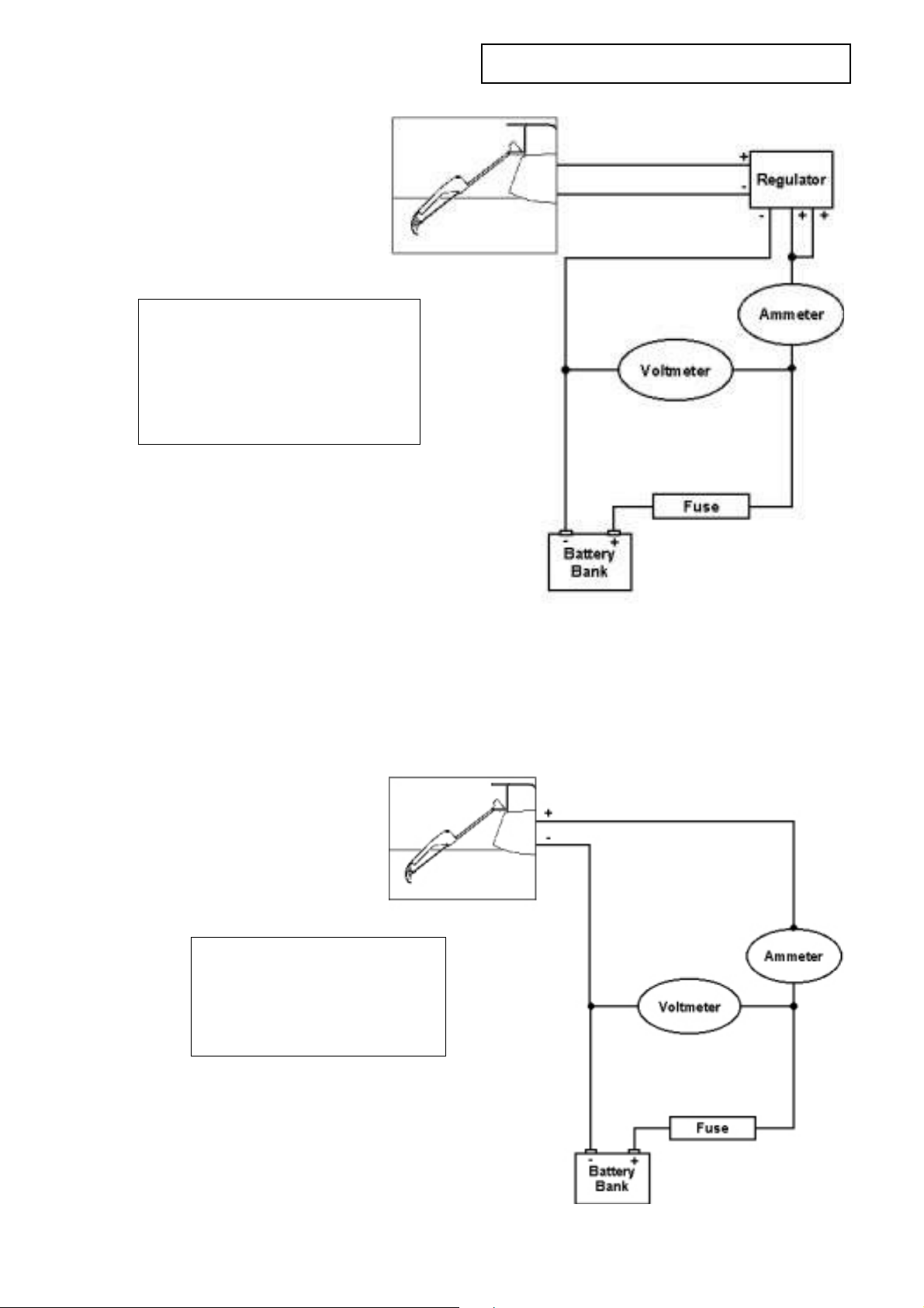
Wiring diagram showing single battery bank
with regulator
We recommend that the DuoGen is
permanently hard-wired. The cable
should enter the yacht via a deck
gland and connection made to the
battery wiring using a waterproof
junction box.
Electrical Connections
Electrical Connections
Electrical ConnectionsElectrical Connections
The DuoGen must always be connected to a battery
when in use, otherwise a dangerously high voltage
can be generated at the output cable.
Wiring diagram showing single battery
bank without regulator
The use of deck plugs and
sockets is not recommended.
These can become accidentally
unplugged, and the plug pins
then constitute a shock hazard.
If in doubt, refer to a competent electrical
engineer or the manufacturers.
7
Page 9
Deploying DuoGen in Wind Mode
Deploying DuoGen in Wind Mode
Deploying DuoGen in Wind ModeDeploying DuoGen in Wind Mode
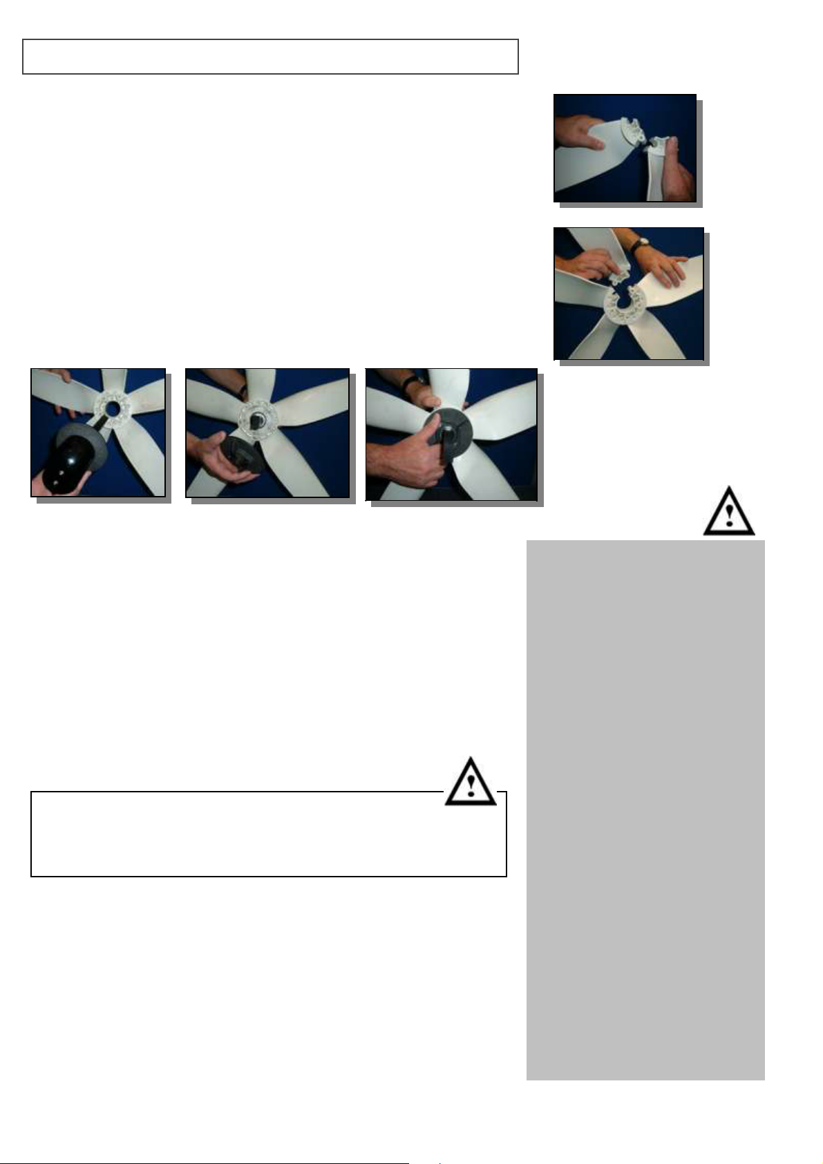
To assemble the wind turbine:
we recommend that you kneel and work on a firm surface, such
as the cockpit floor - this not only makes the operation easy, but
also makes it very unlikely you will drop any components
overboard!
slide the key on one blade root into the keyway on the next blade
continue in this way until you have assembled four blades
with the assembly resting on the floor with the gap uppermost,
position and slide the fifth blade into place
the air drive hub features concentrically arranged conical pins -
identify the matching conical recess in the turbine blade assembly
offer the turbine hub up to that side, aligning the pins with
the recesses
to complete the assembly, screw the clamping plate onto the
hub and tighten firmly
Spring pawls are fitted in the clamp plate to prevent vibration
from loosening it, and you will hear these clicking as
you tighten the clamp plate.
Use only firm hand pressure to tighten the clamp plate.
The spring pawls are factory set and secured with a thread-
locking compound. Do not attempt to adjust these in any way.
visually check that both hub and clamp plate are firmly seated
on the blade roots - there should be no gaps or movement
evident in the completed assembly
Care should be taken when dismantling and
re-assembling the air turbine rotor, as, for maximum
aerodynamic efficiency, the blades feature fine trailing edges
which can cause injury if not handled with caution.
Before attaching the air drive to the yaw arm :
check that the upper tower clamp is securely closed and that
the locking pin is in place (see box right and pictures on Page 9)
check that the alternator yoke is locked centrally by tightening
the thumbscrew on the ‘c’ bracket
orientate the yaw arm so that you will be fitting the
turbine downwind, and ensure that it remains
downwind throughout the operation
The upper tower clamp holds
the machine in a vertical position
when operating in wind mode.
The clamp features a two stage
locking mechanism in order to
prevent accidental release when
the machine is running.
It is essential to ensure that this
clamp is secure. The clamp is
closed by swinging the hinged
retaining bar across the clamp
such that it engages in the gate
opposite the hinge.
The knurled thumb nut is then
tightened until the DuoGen’s
tower is gripped firmly by the
clamp.
Finally, the safety locking pin is
inserted which prevents the
thumb nut from becoming loose
due to vibration.
Note, when fitting the locking pin,
its lanyard should pass around
the tower as this acts as an
additional failsafe.
NB: If difficulty is experienced
when trying to close the clamp,
ensure that it is correctly aligned
and square to the tower tube.
8
Page 10
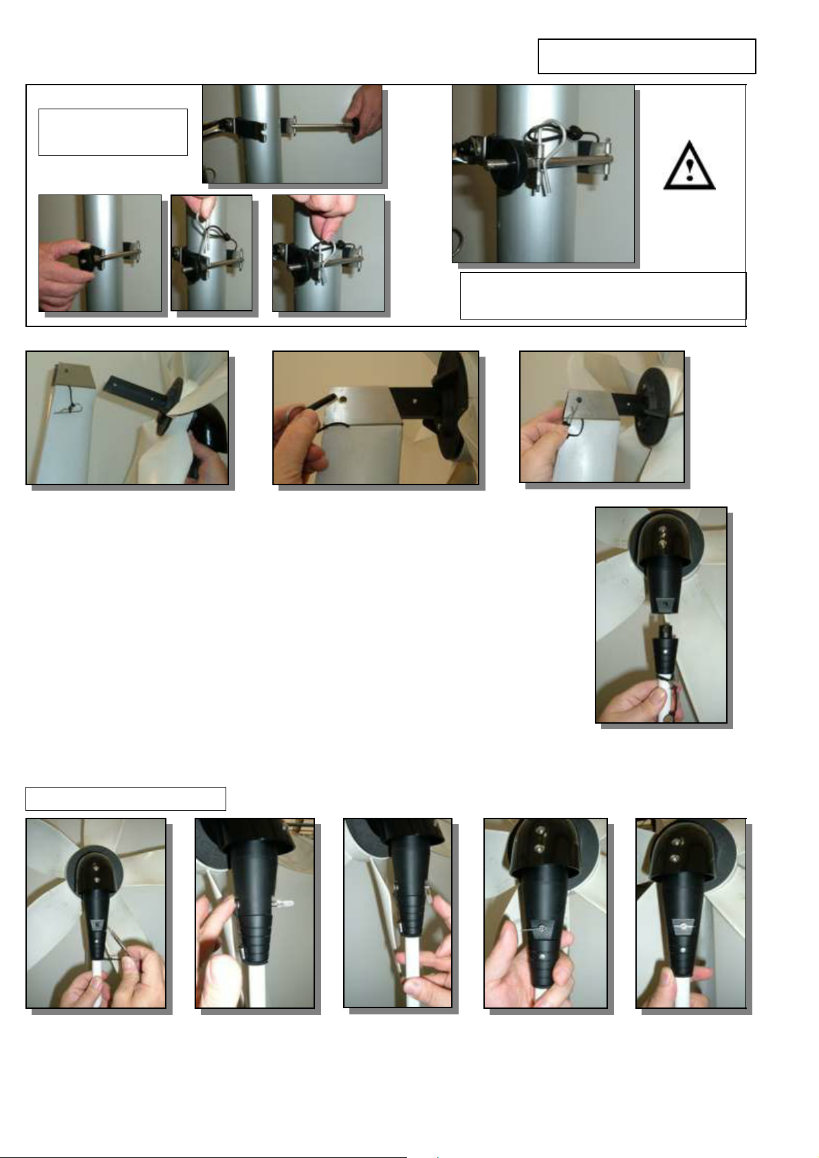
Operating the upper
tower clamp
Wind mode 2
Wind mode 2
Wind mode 2Wind mode 2
Always lock the upper tower clamp as
above before operating in wind mode
grip the air drive in one hand, holding a blade with the other to prevent
rotation offer the air tenon up to the yaw arm socket
align the holes in the yaw arm and the air tenon, and insert the mortice
pin and lock with the beta pin.
once the tenon is located in the socket, tie a short piece of line around
the blades and the yaw arm to prevent blade rotation
extend the telescopic drive shaft until the conical connector boss mates
with the air drive
rotate the drive shaft until the holes align and insert the drop nose pin
Note that the 5 mm bolt which holds the conical connector to the drive shaft can
be used as an alignment aid. Simply align the head of the bolt with the hole in
the air or water drive, and the drop nose pin should pass through easily.
Securing the drop nose pin
Ensure that you rotate the drop nose tab through 90° and push backwards so that it forms a ‘T’ -
this is the lock position for the pin as the tab is retained by a ball spring.
9
Page 11
Wind Mode 3
Wind Mode 3
Wind Mode 3Wind Mode 3
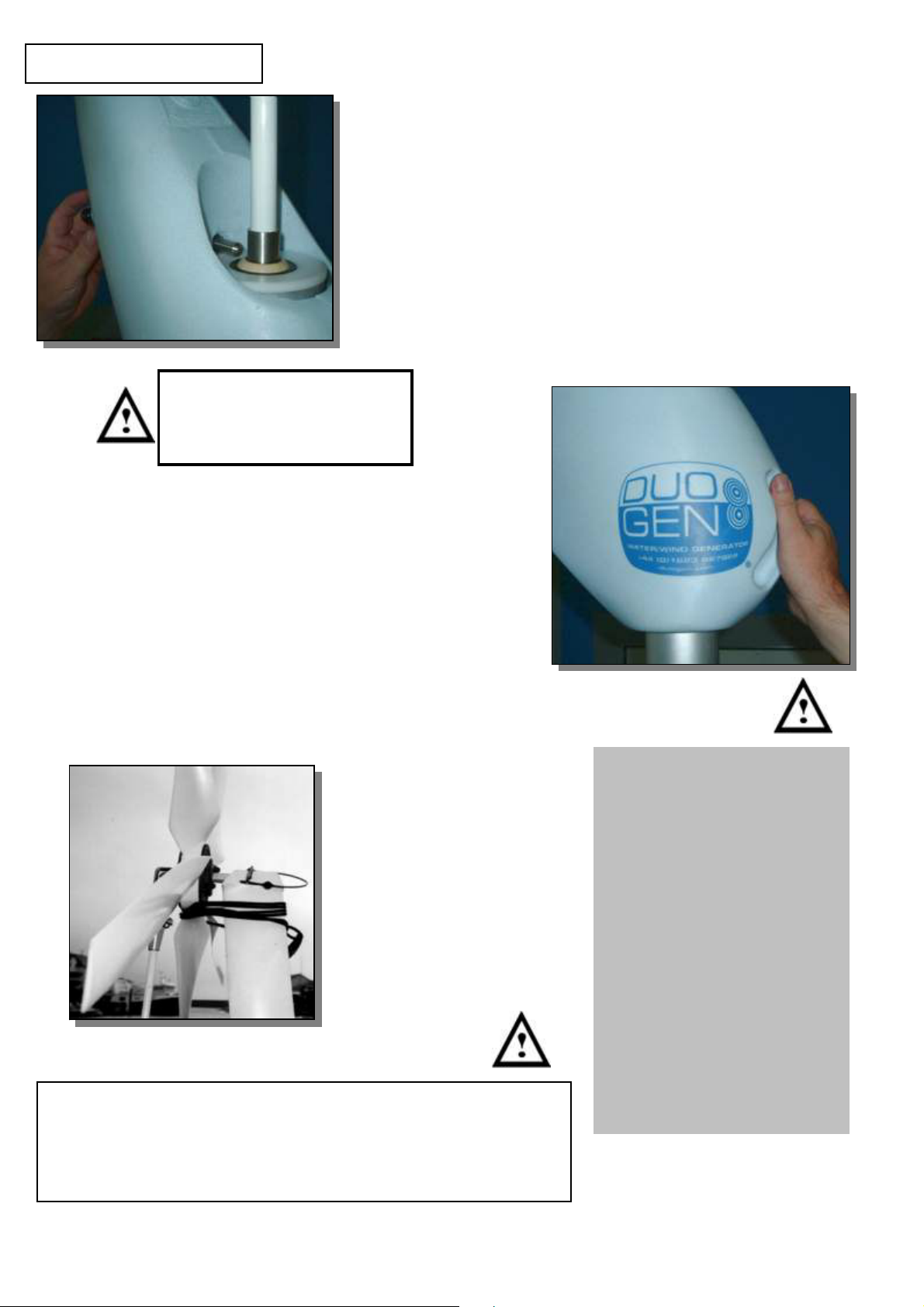
holding an air blade to prevent rotation, remove the
lashing on the blades
raise the yaw arm to the top of the tower and release the
spring plunger by rotating the black knob anti-clockwise
note that in wind mode the plunger rests on the top tower
bearing rather than being located in the yaw arm lock hole
finally, release the air blade and, using the yaw arm
handle, turn the turbine into the wind. The turbine will
begin to run.
NOTE: DuoGen should always be
stopped using the moulded yaw
arm handle, even where an
electrical brake switch is fitted.
To stop DuoGen wind mode:
grasp the moulded yaw arm handle and turn the machine
gently through 180º
the turbine will slow down and stop
as soon as it stops, grip a turbine blade to prevent
rotation
(the blades will run backwards down wind!)
release the spring plunger and lower the yaw arm
Never be tempted to hold the turbine by the air drive tenon
and let it run in the wind. This is highly dangerous.
The turbine will accelerate very rapidly, and the forces
generated will become unpredictable and difficult to control,
due to the gyroscopic effects.
Air blades
In wind mode, as with all wind
turbines, the major hazard lies
in accidental contact with the
turbine blades. Although the
DuoGen's blades run more
slowly than many competitor
machines, they are still capable
of inflicting injury.
When correctly installed and
operating, the DuoGen's air
blades are safely above head
height. By using the handle on
the machine's yaw arm, DuoGen can quickly be stopped
even in severe conditions,
without any risk of injury from
the blades.
10
Page 12

Furling in Wind mode
Furling in Wind mode
Furling in Wind modeFurling in Wind mode
The DuoGen’s wind mode incorporates self-furling.
This can be viewed as analogous to a yacht heeling to gusts of wind.
In light breezes, the DuoGen’s air rotor will point almost directly at the wind. As the wind speed increases, it
will begin to furl about the main tower pointing progressively off the wind.
Once a gust has passed, the air rotor will move back more closely to the wind direction.
The effect of this furling action is to progressively reduce the intercept area of the air rotor in response to
rising wind speeds, in much the same way that heeling reduces effective sail area on the yacht.
High electrical outputs are maintained, but the wind loading on the DuoGen, its mounting and ultimately
the yacht’s moorings, are controlled. In moderate breezes, the rotor may sit 5º to 10º off the wind, and in
high winds 20º to 30º. In practice, you will observe the DuoGen furling gently as a heavy gust of wind
strikes, and then return to its original position as the gust passes.
The furling force is provided by the alternator’s reluctance to be accelerated. This furling force is balanced
by the wind loading on the air turbine rotor, and the DuoGen’s yaw arm, which acts like a tail.
In certain conditions, excessive or erratic furling may be observed. Probable causes are:
a) the operation of the regulator - as the regulator starts to dump power, the alternator suddenly becomes
‘stiffer’ to turn and this produces a large increase in the furling force.
b) turbulent air - as the furling force is balanced primarily by the wind loading on the rotor disc, turbulence
and sudden ‘holes’ in the wind can result in an excessive and erratic furling action. Such turbulence is
usually caused by obstructions upwind or down wind of the turbine, and are particular to a certain
location and wind direction.
c) mechanical or electrical fault - usually indicated by low or no electrical output, and/or undue
mechanical friction and noise.
d) stiffness in the yaw bearing - usually caused by dirt or salt on the bearing surfaces. The yaw bearings
are of a dry running plastic type, designed to run on anodised aluminium.
Periodic flushing with fresh water and polishing the tower tube with a silicone-based furniture polish should
restore free movement.
When lying at anchor with the wind mode deployed, the furling action can be disabled by inserting the
yaw arm spring plunger in the 10 mm hole at the top of the main tower. This locks the yaw arm with the air
rotor facing directly towards the bows. The yacht herself now keeps the air rotor pointing at the wind, and
power outputs for a given wind speed will generally be higher.
A similar effect can be achieved by restraining the yaw arm with shock cord or a lashing.
We recommend that you restore the furling action if the wind speed exceeds 25 knots or if you
leave the boat.
11
Page 13
Deploying DuoGen in Water Mode
Deploying DuoGen in Water Mode
Deploying DuoGen in Water ModeDeploying DuoGen in Water Mode
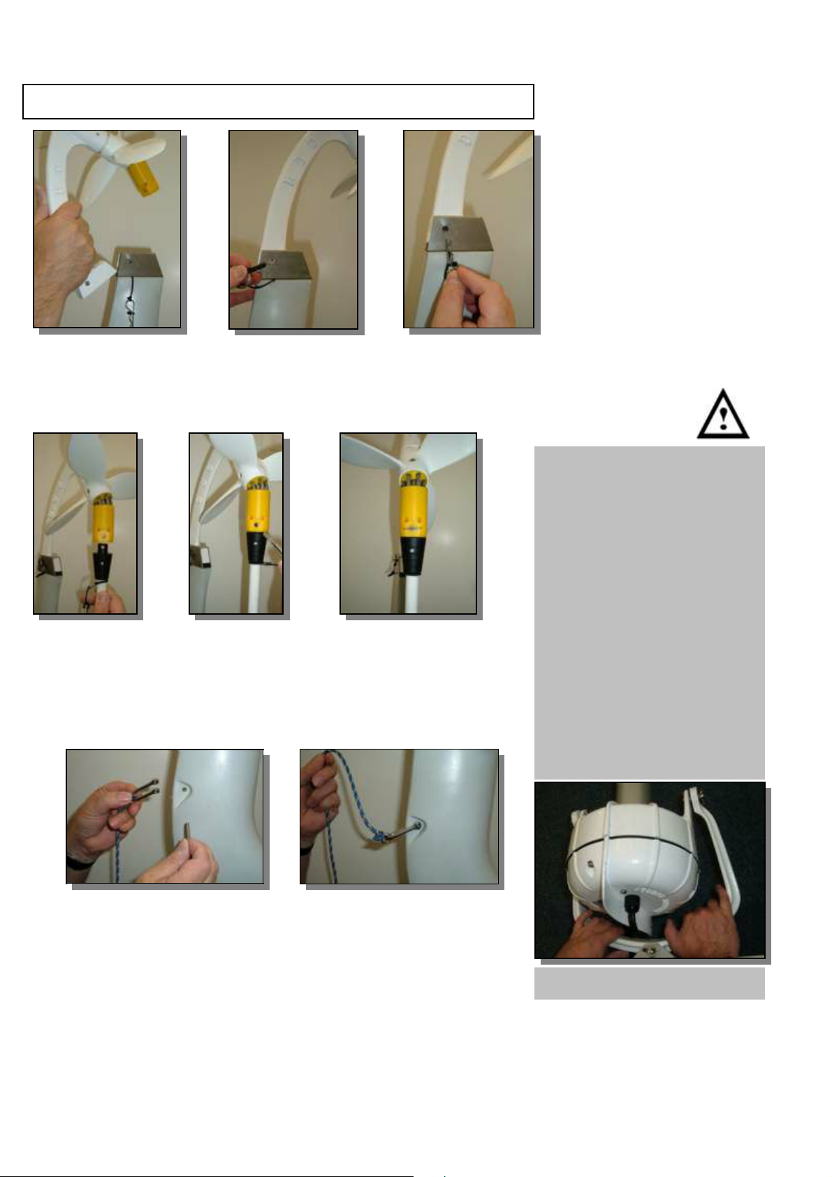
release the yaw arm spring plunger and lower the yaw arm to stop
insert the water bracket tenon into the rear of the mounting socket on the yaw
arm
secure with the mortice pin and beta clip
extend the drive shaft until the connector boss mates with
the impeller transmission
rotate the drive shaft until holes align and insert the drop
nose pin
The DuoGen's water mode
pivots in two planes at the
alternator mounting to allow for
manoeuvring the yacht and for
wave action. In common with
other water generators, this
hinging creates a potential trap
hazard for hands and fingers.
The DuoGen is designed with
generous clearances to
minimise the risk of accidental
crush injuries. Nevertheless,
handling the alternator and its
mounting yoke when the water
mode is deployed should be
avoided.
attach the recovery lanyard to the shackle on the yaw arm
form a loop on the inboard end and drop it over the hook on
the upper tower clamp
adjust the length of the lanyard such that it holds the DuoGen
clear of any part of the yacht’s structure (i.e. steering system
servo oars) when the yacht is stationary
the lanyard should hang loose when the yacht is underway
and the DuoGen is operating normally
12
DON’T PUT YOUR HANDS HERE!
Page 14
Water Mode 2
Water Mode 2
Water Mode 2Water Mode 2
To deploy in water mode:
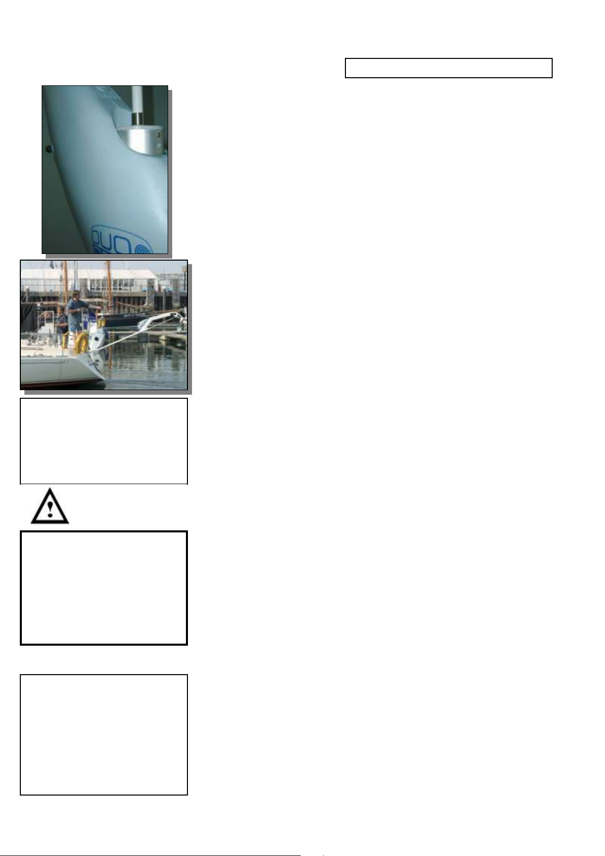
raise the yaw arm to the top of the tower.
You must ensure that the spring plunger is located in the
locking hole at the top of the tower.
This prevents the yaw arm from rotating around the tower and
‘capsizing’ the water impeller when underway
to locate the locking mechanism, align the etched marks on
the yaw arm with the top of the main tower.
release the spring plunger by rotating the black ball knob anti-
clockwise (downwards), and move the yaw arm gently side to
side until the spring plunger clicks into the lock hole
remove the upper tower clamp locking pin and unscrew the
thumb nut on the retaining bar and pivot it clear of the tower
holding the recovery lanyard, push DuoGen backwards freeing
the tower from the tower clamp.
the unit can now be gently lowered into the water using the
recovery lanyard
Running in Water Mode
DuoGen’s alternator yoke allows
freedom of movement in two
planes so that wave and helm
action can be accommodated.
WARNING: the DuoGen
should never be allowed to
operate if it is not connected
to a battery. This condition
allows the machine to
over-speed and very high
voltages can be produced.
NOTE:
Although you can motor slowly
astern with the DuoGen
deployed,we
recommend that it is not
deployed until the yacht is
moving slowly ahead.
Due to its closed cell foam filling the yaw arm is naturally buoyant.
However, if the yacht is stationary and a sea is running, the relative
movement of the yacht and the DuoGen can cause the tower to
bump against the transom of yachts with retrousse sterns.
To avoid this, tie a loop in the recovery lanyard and drop it over the
hook incorporated in the upper tower clamp assembly. Adjust the
length of the line such that it becomes taut just before the DuoGen’s
tower contacts the yacht’s transom.
Note that using the recovery lanyard to limit downwards travel of the
DuoGen is very important, particularly when the unit is installed on a
multihull. Catamaran hulls can ‘bridge’ a wave and trough, allowing
an unrestrained DuoGen to fall almost to the vertical. Once in this
position, the horizontal pivot at the ‘c’ bracket can no longer
effectively dissipate side forces, and damage to the yoke and
alternator casting may result.
In normal operation when the yacht is underway, the recovery line
will hang loose, as the DuoGen rides on its diving plane at an angle
of 35 - 40º to the water surface.
Having deployed the DuoGen water mode, ensure that you
release the alternator yoke by unscrewing the black
thumbscrew on the ‘C’ bracket.
This allows the alternator yoke to pivot laterally.
13
Page 15
Water Mode 3
Water Mode 3
Water Mode 3Water Mode 3
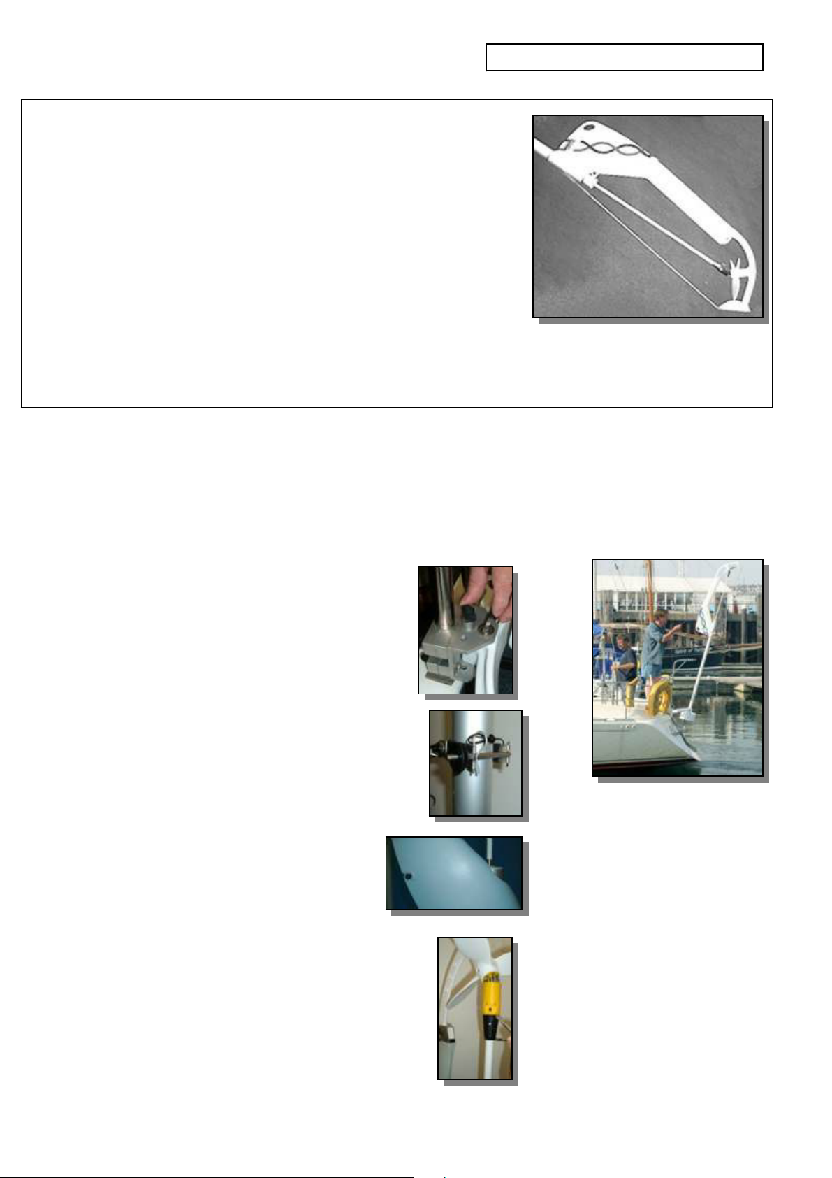
A clearing line can be utilised if clogging of the impeller is a problem.
This is best accomplished with the piece of 3 mm pre-stretched line
supplied, secured by a stopper knot through the hole in the diving plane,
and the other end made fast to the shackle above the moulded handle
recess in the yaw arm.
Alternatively, the clearing lines can be secured to a loop of line attached
to one of the holes in the alternator backplate fin. This option allows the
clearing line to be used to assist recovery of the DuoGen without
reducing boat speed.
Refer to section on ‘Recovering water mode’ overleaf.
Two additional holes are provided at the tips of the diving plane and
further lines can be passed through these and secured in a similar
manner to provide even more protection against floating debris.
Recovering the DuoGen from Water Mode
To recover the DuoGen from water mode with the yacht stopped or moving slow ahead:
centralise the alternator yoke and tighten
the ‘C’ bracket thumbscrew - this will
lock the yoke in its central position
using the recovery lanyard, pull DuoGen
out of the water and back to the vertical
clip the tower into the upper tower clamp and
re-secure the knurled thumb nut
fit the failsafe locking pin, looping the lanyard
around the tower for extra security
(see page 8)
pull the black knob which actuates the
spring plunger rearwards and rotate
anti-clockwise to lock
the yaw arm can now be lowered to its stop
withdraw the drop nose pin and disconnect
the drive shaft
withdraw the mortice pin and remove
the water turbine assembly from the yaw arm
14
Page 16
Water Mode 4
Water Mode 4
Water Mode 4Water Mode 4
To recover the DuoGen from water mode with the yacht underway:
The weight of the DuoGen’s alternator helps to balance the weight of
the tower, making the DuoGen easy to raise and lower using the
recovery lanyard when the yacht is stationary.
However, when the yacht is underway, the hydrodynamic force
generated by the diving plane, which prevents the water impeller from
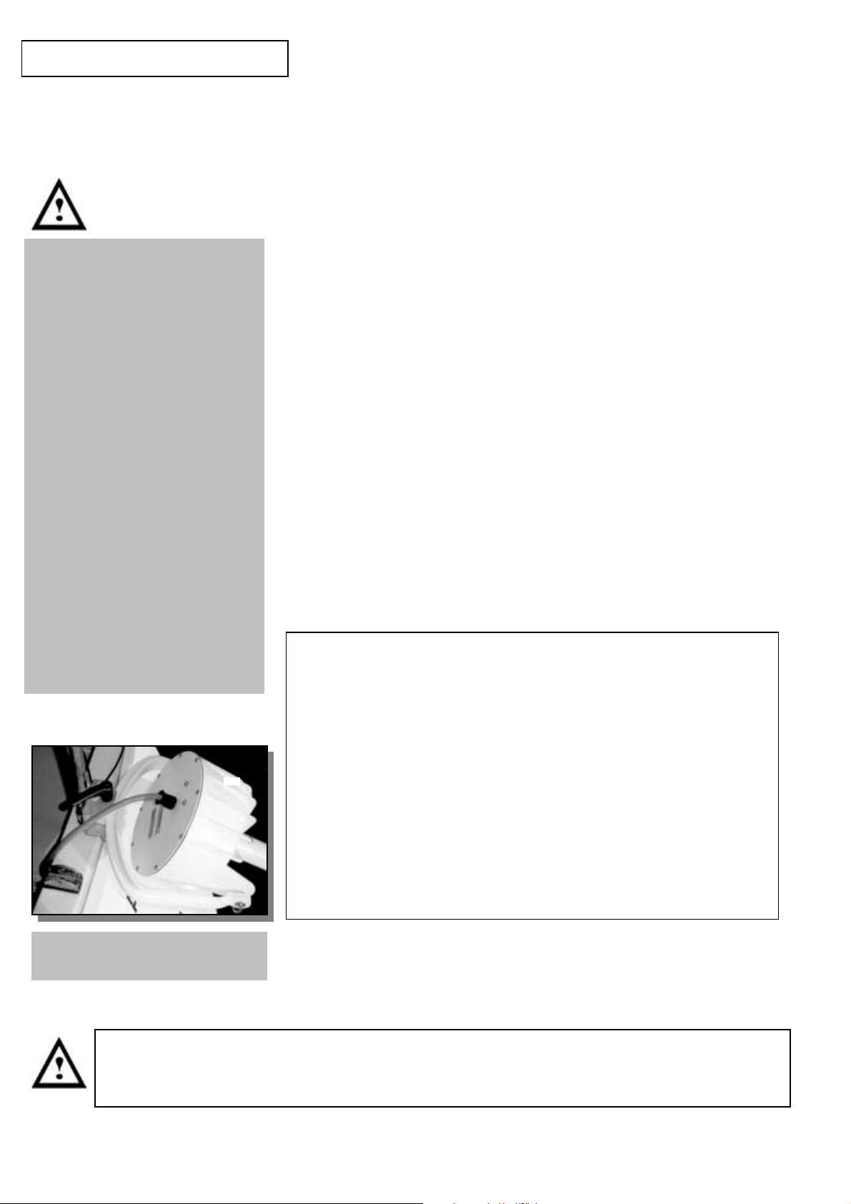
Ensure that electrical
connections are secure and
permanent.
Always fit an in-line fuse
Do not use crocodile clips or
temporary connectors.
Use a waterproof gland where the
cable passes into the boat. Use
extension cable which is at least
the same cross-sectional area as
the cable supplied with the
DuoGen, that is 4.5 mm².
Corroded connections are the
single biggest cause of electrical
failures on yachts. It is good
practice to smear battery
terminals and other exposed
connections with petroleum jelly in
order to prevent this.
Once the DuoGen is installed, it
is not necessary to disconnect
the electrical connections when
changing mode.
surfacing, also makes it difficult to raise the DuoGen at boat speeds
over 3 knots.
Prior to recovering the DuoGen from its water mode, either:
slow the yacht to 3 knots or less, OR
cut the top off a plastic bottle, and allow it to slide down the
clearing line. This will lodge at the diving plane and break the
water flow, making the DuoGen easy to raise, OR
install a longer recovery lanyard via a small block off the
backstay or other convenient point, such as a davit. The
enhanced lead angle and purchase this will provide should make
recovery much easier.
The Diving Plane
Ensure that the cable runs freely
and without obstructions.
Should the DuoGen be vibrating or unduly noisy in operation, it should be stopped
immediately whilst the cause is identified. DuoGen should never be allowed to run with
damaged, cracked or misaligned turbine or impeller blades.
The running depth of the DuoGen’s water impeller unit is controlled
by the diving plane. The impeller usually operates in the top 500 mm
of water and 300 mm is a typical depth for the impeller hub.
The foil can be adjusted to allow the impeller to run a little deeper or
shallower if required. Note that the mount height of the alternator also
has an effect on running depth, so raising or lowering the pivot point
height is an additional or alternative option.
The diving plane is adjusted by loosening the M8 bolt and nut,
together with the allen head locking screw immediately below. The
foil can be moved several degrees either side of a ‘mean’ indicated by
the alignment marks in the casting.
Tighten the M8 bolt in the new position and finally tighten the lock
screw to secure.
15
Page 17

Repairs and Maintenance
Repairs and MaintenanceRepairs and Maintenance
The DuoGen is designed to require minimal maintenance, but a
little attention will pay dividends in terms of appearance and
performance.
Periodic washing with fresh water will remove accumulated salt
deposits and keep the yaw bearings and the telescopic drive shaft
sliding smoothly. An occasional application of a domestic siliconebased polish on the tower tube and drive shaft is also
recommended.
The alternator requires no maintenance as it is hermetically sealed,
and the bearings are protected by a twin lip radial shaft seal.
The water mode is robust and efficient, and maintenance free as the
impeller transmission device is lubricated by a combination of synthetic
oil within the matrix of the bearing material and water.
When dry following immersion in sea water, the unit may feel a little
stiff. This is due to dry salt deposits and the unit should free up
immediately it is returned to the water.
SPARE PARTS
We recommend that you carry
the following parts in case of
loss or damage:
1 x drop nose pin
1 x air turbine blade
1 x mortice pin
2 x 40 amp fuses (12 V)
OR
2 x 20 amp fuses ( 24 V)
1 x tower lock pin
1 x ‘C’ bracket lock screw
1 x air drive grease
However, the DuoGen’s water impeller rotates about 5 million times for
every thousand miles sailed, and like all mechanical devices, is prone
to wear.
We recommend that the transmission elements are replaced every 8
- 10,000 nautical miles, or 40 - 50 million revolutions, in order to
maintain optimum performance. This is a straightforward procedure
that can be undertaken by the owner.
The DuoGen’s air mode transmission device incorporates a heavy
duty gear set and thrust bearings, all running behind grease seals.
The gear faces benefit from the occasional light application of a
good quality weather resistant grease, as supplied.
information, spare parts and repairs, contact
Unit 22 Sherwood Networkcentre
1 x Set of water drive bearings
1 x conical connector kit
1 x acetal gear replacement kit
(A spares pack containing these
parts is available)
CONTACT DETAILS
For after sales service and
Eclectic Energy Limited
Sherwood Energy Village
Ollerton
Nottinghamshire
United Kingdom
NG22 9FD
16
phone: +44 (0)1623 835400
fax:+44 (0)1623 860617
e-mail: [email protected]
Page 18
Regulation
Regulation
RegulationRegulation
The DuoGen is capable of delivering sustained levels of high power.
Therefore it is important to ensure that overcharging does not occur.
Overcharging is characterised by excessive battery terminal voltages and loss
of electrolyte. Permanent battery damage can result.
The two main strategies to avoid this are:
Manual Monitoring
This entails monitoring battery state and simply starting or
stopping the DuoGen as required, For owners who live aboard this is a
viable option, particularly if the battery bank is of high capacity.
Dump Regulation
Eclectic Energy Limited or your supplier can supply a dump regulator
which is installed close to the batteries. The regulators are factory set at
14.2 (12 V) and 28.4 (24 V). The regulator is adjustable between 11.5
and 17 V. You set the voltage in accordance with the battery
manufacturer's recommendations and as this voltage is reached, the
regulator progressively diverts the DuoGen’s output to a pair of large
wire wound resisters where the excess power is lost as heat.
The Pros and Cons of Regulation
Eclectic generally recommends that the DuoGen is used in conjunction with a
regulator. However it is important to be aware of their limitations.
As regulators work by sensing battery terminal voltage, any other device that
raises that voltage, such as a solar panel, can cause the regulator to dump
power prematurely.
For this reason, where possible, a single regulator should be used. The
regulator usually supplied with the DuoGen is rated at 40 amps (12 V) or 20
amps (24 V). As well as the DuoGen, the regulator will also accept the input of
up to 150 watts of solar panel.
If this is not practical, an alternative solution is to install the regulator with a
bypass switch. On passage when you can monitor the system, bypass the
regulator and avoid unwanted dumping of power. When you leave the boat,
switch it back on.
Note that where a bypass switch is fitted, the charge splitting function of the
regulator is also bypassed when the switch is activated.
We recommend that the bypassed output is fed to the largest bank (usually the
service batteries). Alternatively, a dedicated charge splitter can be installed to
distribute the unregulated output across two banks.
17
Page 19
Commissioning
Commissioning
CommissioningCommissioning
With installation steps complete, you should be ready to operate
DuoGen for the first time. Before starting the machine it is advisable to
take a moment and:
- check that all fasteners on the mounting brackets have been fully
tightened
- check that the electrical connections are secure and well made, and
that the cable exiting the alternator does not snag or pull as the DuoGen
moves from one mode to another
- check that the line fuse has been replaced in the fuse holder
With the yaw arm in its raised position and the airblades fitted (tied off
with a piece of line to prevent rotation), turn the arm through 360º to
ensure there is no possibility of contact between the blade tips and
other equipment mounted on the yacht.
System Monitoring
System Monitoring
System MonitoringSystem Monitoring
It is notoriously difficult to monitor wind turbine performance in real
world conditions because the wind is dynamic, continually fluctuating in
both direction and strength.
The most accurate performance assessment can be obtained with a
hand-held anemometer at turbine hub height, and a digital ammeter
connected in line between DuoGen and the regulator.
However, given due consideration of the points made earlier, the ship’s
mast head anemometer and battery monitor are perfectly adequate to
ensure that your system is working well.
Refer to the section on page 6 (Electrical Connection) to ensure the
ship’s battery monitor can ‘see’ DuoGen.
If you are still unsure that the system is working as it should, do not
hesitate to contact us and we will do all we can to resolve the problem.
18
Page 20

Performance and expectations
The DuoGen was specifically designed to maximise zero carbon electricity generation on
cruising yachts. The DuoGen’s unique wind/water capability works best where yachts are
making frequent or long sea passages, interspersed with periods at anchor or in
harbour.
The DuoGen should perform in line with the values given in our published output graphs.
However, when monitoring the system, there are external factors that can effect
performance, and may lead you to falsely conclude that there is a problem. To assist in
accurate evaluation, particularly in relation to wind mode, be aware of the following:
when monitoring the wind mode, wind speed measurement should be made at
the height of the turbine rotor. Where a mast head anemometer is used, there
will be significant wind shear, and it is not unusual for wind speed measurements
at turbine level to be 5 - 6 knots lower than the masthead. This is particularly true
in harbours and marinas.
when measuring performance, battery state is also important. Fully charged
batteries do not readily accept current, and where a charge regulator is fitted, any
dumped power will not be registered by the ship’s battery monitor. In addition,
where batteries are fully charged, or the regulator is ‘dumping’, the load seen by
the DuoGen’s alternator changes. This makes the alternator ‘stiffer’ to turn, which
in turn increases the force which furls the turbine. The increased furling angle
reduces the intercept area of the DuoGen’s air rotor which in turn lowers the
electrical output.
When evaluating the DuoGen’s air mode, try to ensure batteries are 30 - 40%
discharged, or alternatively switch on numerous loads in order to pull the
battery voltage down.
if wind mode outputs remain below expectations, first suspect turbulence in the
wind stream. Turbulence at a given site can be specific to a particular wind
direction where it is caused by an obstruction either up or downwind of the turbine.
When the wind direction changes, and the obstruction is no longer in line with the
turbine, outputs may return to expected levels.
if poor output cannot be attributed to site conditions, re-check the whole
installation against the wiring diagram and also look for poor or loose
connections. Also, check fuses and fuse holders.
finally, ensure that the batteries are in good condition and of sufficient
capacity. We recommend a minimum of 300 Ah for use with the DuoGen.
If you still suspect a problem with the machine, consider the following:
do the air blades spin freely? The air rotor should spin without any undue noise
or friction. If not, is there a braking switch engaged or could there be another
short circuit in the output cables? (Make sure you disconnect the batteries before
trying to find out!)
is the DuoGen free to move about its yaw axis? It should move easily with no
undue noise or friction.
If in doubt, refer to your dealer or the manufacturer.
Note that there is a short period of ‘running in’ with a new wind turbine. The bearings
and shaft seals of a new machine take 40 – 50 hours of operation before mechanical
friction falls to its design level. As a result, your DuoGen may seem a little slow to
respond in light winds until this ‘running in’ period has passed.
19
Page 21

Your Notes
www.eclectic-energy.co.uk
DECLARATION OF CONFORMITY
We declare that this product complies with the
following standards/directives:
89/336/EEC
Product description: 'DuoGen' Alternator
Model number: EE100
Serial number:
Signed:
Dated: Director
Eclectic Energy Limited
Unit 22 Sherwood Networkcentre
Sherwood Energy Village Ollerton
Nottinghamshire
United Kingdom +44 (0) 1623 835400
NG22 9FD
GUARANTEE
DuoGen is guaranteed against faulty parts and manufacture for a period of
twelve months from date of purchase. The unit should be returned prepaid
to:
Eclectic Energy Ltd Unit 22 Sherwood Networkcentre
Sherwood Energy Village Ollerton
Nottinghamshire United Kingdom NG22 9FD
Damage caused by mishandling, faulty installation or accident is not
covered. Eclectic Energy can not be liable for damage caused by DuoGen
in the event of accidental contact, incorrect installation or insufficient care.
However, Eclectic Energy Limited is committed to provide after sales care
as fully and efficiently as possible in order to support our customers.
This guarantee does not affect your statutory rights.
20
Page 22
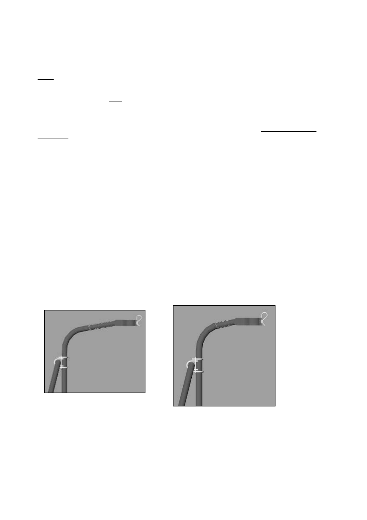
Appendix
Appendix
AppendixAppendix
DuoGen Universal Mount Bracket Installation
1. Read all the instructions carefully before commencing installation and familiarise yourself with
the components.
2. Allow yourself plenty of time, at least four hours. Fitting DuoGen is not difficult, but it is
unfamiliar, and rushing doesn't help! If you can enlist an assistant the job will be much easier.
3. There is nothing worse than dropping tools or fasteners overboard! It is usually well worth the
effort of inflating the dinghy and securing it across the transom so you can tackle the job from
both sides. Alternatively, bring the yacht in stern to so her transom can be reached from the
pontoon.
4. You will see that, when installing using the universal bracket, the bracket becomes a new
vertical pushpit member.
5. Consider the diagrams and photographs and decide how best the universal bracket can be
attached to your yacht.
6. It is often useful to offer the bracket up to the rails in a variety of positions before beginning to
attach it with rail clamps. Note that some drilling and sawing operations may be required. The
universal bracket is made of 316 stainless steel and is very hard. Make sure you have a new
high speed steel hacksaw blade available and a new high speed steel 5 mm drill bit. It will save
a lot of frustration!
7. Depending on the architecture of the yacht and the tower length of the DuoGen, it may be
necessary to shorten the universal bracket at one or both ends. This is easily done by simply
sawing a length off. In some rare cases, notably where an extra long tower machine is being
fitted and where the universal bracket foot falls a long way down a transom, the universal
bracket may require extending. An extension kit is available to achieve this.
8. Check the pushpit rail diameters. The clamp plates and U bolts supplied with the mount kit are
designed to fit 25 mm (1 inch) rails. If your rails are 32 mm (1¼ inches) you will require 4 larger
U bolts to suit. You will also require a larger rail clamp to secure the end of the lateral brace
strut. These parts can be sourced locally or via Eclectic Energy Limited.
21
Page 23
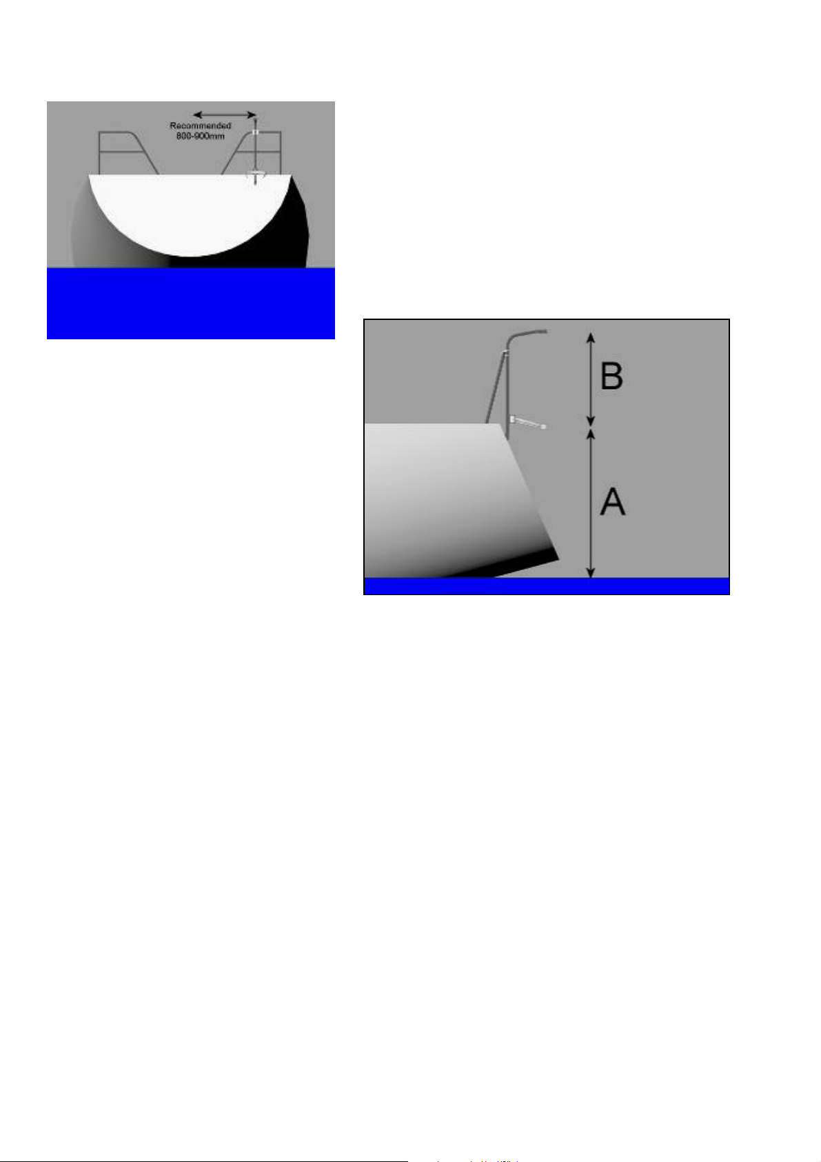
10. Aim to secure the universal bracket
such that it is vertical when viewed
from the stern and the beam. The
upper part of the bracket should be
aligned fore and aft.
Refer to the appropriate mounting
schematic for the tower length of your
machine and ensure that dimensions
A (alternator pivot point to static water
line) and point B (alternator pivot point
to upper tower clamp) fall within the
given parameters.
9. Where possible, keep the mounting within 800 –
900 mm of the yacht’s centre line. This minimises the
difference in running depth of the water mode from
tack to tack and optimises performance. If the
mounting has to be made further out on the quarter,
the machine will still work perfectly on most points of
sail. With DuoGen on the windward quarter, the
impeller may occasionally break the surface when
the yacht is close handed with her rail hard down. It
will rebury immediately as soon as the angle
moderates.
11. Where it is possible to clamp the universal bracket on both the upper and the middle pushpit
rails, it may be sufficient to bond the bracket foot to the deck or coaming with Sikaflex or
similar. Through bolting remains preferable. Substantial screws could also be used. However, if
for practical or aesthetic reasons you prefer not to drill the boat, bonding is an option provided
there are two solid mechanical joints above.
12. Where the universal bracket is clamped to the upper rail only, the foot must be through-bolted
to the deck, coaming or transom, depending on where it falls. The bracket should be secured
with M6 stainless steel nuts and bolts. As drilled holes are permanent, it is a good idea to
secure the bracket using the rail clamp and temporarily mount DuoGen. Once you are
confident that all is correct, the holes can be marked and drilled.
13. The swivel foot at the base of the universal bracket can be re-orientated through 90º. To
achieve this, remove the foot, drill a new 6 mm hole at 90º to the existing one and re-assemble.
14. On some installations, the universal bracket foot may not meet the deck coaming or transom
squarely. In these situations, a simple wedge-shaped packing piece should be made up from
hardwood, plastic or aluminium.
15. Where the universal bracket foot is through-bolted, it is advisable to fit a backing plate to
spread the load. Alternatively, large ‘penny’ washers can be used.
16. Having secured the universal bracket to the boat, attach the ‘C’ bracket using the M25
aluminium clamp blocks.
22
Page 24
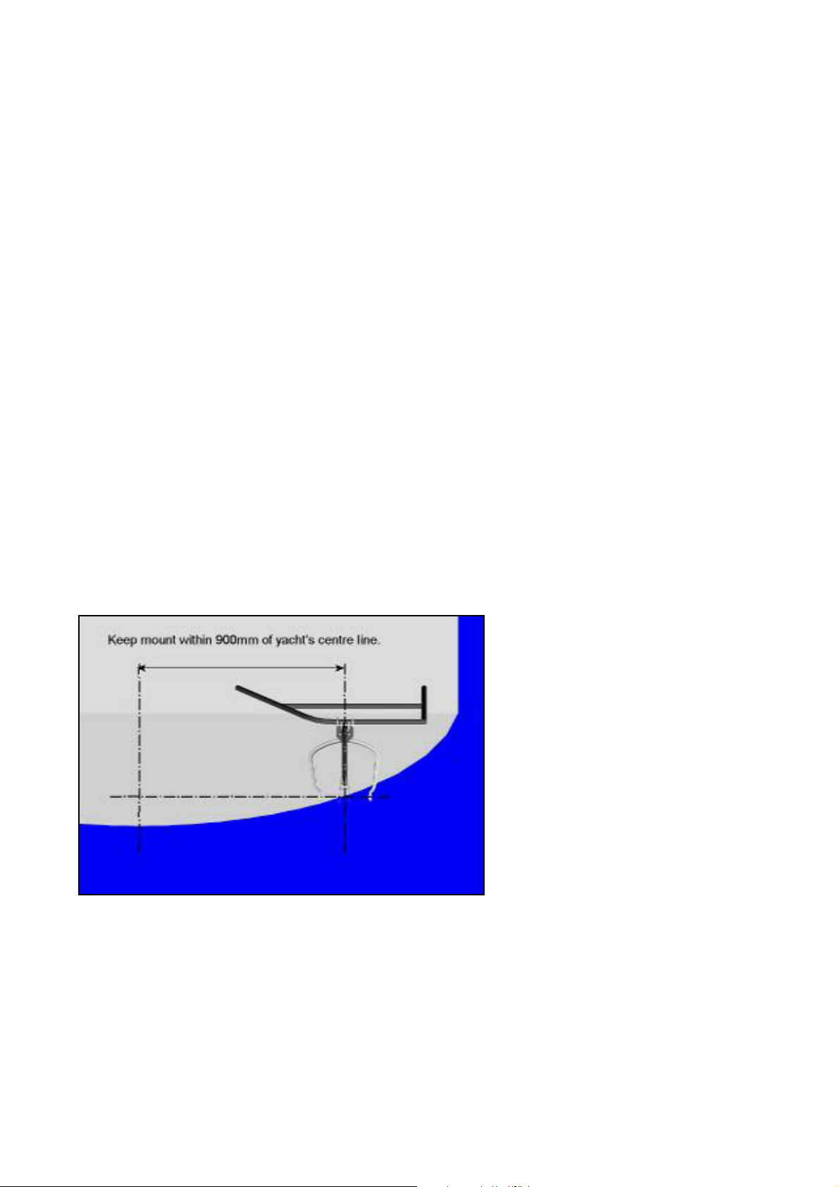
17. Temporarily fit the alternator yoke by installing the 10 mm hinge pin. Centralise the yoke and
tighten the pivot lock mini wing screw. Measure the distance from the alternator pivot point to
the static water line. Slacken the clamp bolts slightly and slide the ‘C’ bracket up or down to
bring the measurement within the parameters specified for the tower length of your machine.
Note that the alternator yoke is reversible and that this has the effect of raising or lowering the
pivot point. Ensure that the yoke is square to the yacht and the upper part of the universal
bracket when viewed from aboard and tighten the clamp bolts.
18. Temporarily fit the upper tower clamp by sliding the 7/8 inch tube inside the upper part of the
universal bracket. Take care to re-fit the rubber anti-rattle ring.
19. Enlist an assistant to help in mounting DuoGen using the short 10 mm pins, passing them
through the bushes in the yoke. The machine is quite heavy and the holes need to be
accurately aligned for the pins to slide home. This is why the job is best undertaken with two
pairs of hands.
NOTE: when properly fitted, the alternator/ tower retaining screw and plunger hole at the top of
the tower should be pointing forward towards the bows.
20. Slide the yaw arm up the tower and raise the tower up to the vertical, locating the tower in the
upper tower clamp. DuoGen’s tower should be vertical when in wind mode. The upper tower
clamp can be slid backwards and forwards in the universal bracket in order to achieve this. If
DuoGen’s tower still leans aft with the tower clamp pushed fully into the universal bracket,
estimate how much further in the clamp would have to go to bring the tower vertical. Remove
the upper tower clamp and cut the estimated length off the end of the 7/8 inch tube. Remove
the anti-rattle ring from the universal bracket and cut a similar amount of the 1 inch tube.
Reassemble and pivot DuoGen back and engage the tower in the tower clamp. Check for
vertical alignment and repeat the process if necessary.
21. When satisfied with the tower
alignment, close the locking
strap on the tower clamp.
Visually check the clamp is
square to the tower tube, and
using first a centre punch, then
a sharp 5 mm drill, drill a hole
through the universal bracket
and into the 7/8 inch tube of the
upper clamp. Then fit the pop
rivet supplied.
22. Next, fit the lateral brace. Offer this up between the bolt which passes through the upper tower
clamp assemble and the pushpit rail. The flattened ‘ear’ attaches at the tower clamp end, and
may require bending slightly in order for it to mate squarely. This is best done in a vice, but a
large shifting spanner or vice grip wrench could be gripped onto the ‘ear’ and used instead.
23. Push the lateral brace rail clamp over the pushpit rail and secure the end of the lateral brace
with the 5 mm nut and bolt provided. Unscrew the nut from the upper tower clamp assembly,
attach the lateral brace and re-secure the nut.
23
Page 25
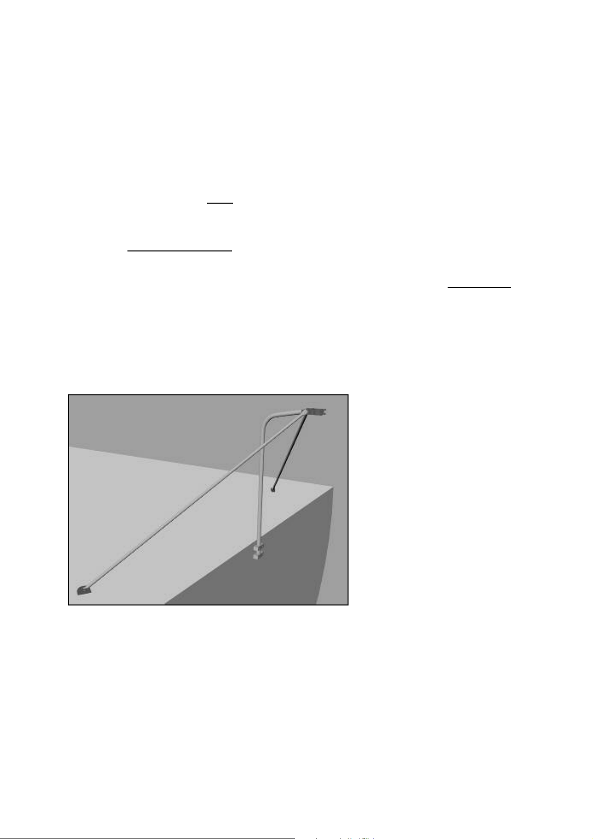
24. Tighten all fasteners.
25. Check that DuoGen pivots freely from wind mode position to water mode. Release ‘C’ bracket
pivot lock mini wing and ensure DuoGen pivots freely from side to side. Centralise the
alternator yoke, re-tighten the ‘C’ bracket pivot lock. Raise DuoGen back to wind mode position.
Ensure that the upper tower clamp strap closes properly and securely with an audible snap. If it
does not, or requires undue force to close it, re-check alignment.
26. Fit nut covers and Tower lock warning sticker.
27. Decide where to bring the cable into the yacht and fit a deck gland. (Do not use deck plugs and
socket.) Allow a reasonable loop of cable so that the cable is not strained as DuoGen pivots
between modes. Raise and lower the machine to make sure the cable runs free.
28. Make the electrical connections in accordance with the guidelines in the manual, and ensure
you fit the in-line fuse. If in doubt, seek qualified assistance.
29. If at any point you experience difficulty or are unsure about how to proceed, contact us.
We will do everything we can to assist you.
Installation without existing pushpit rails.
24
 Loading...