

VBD 662-2 (12.16)
EN
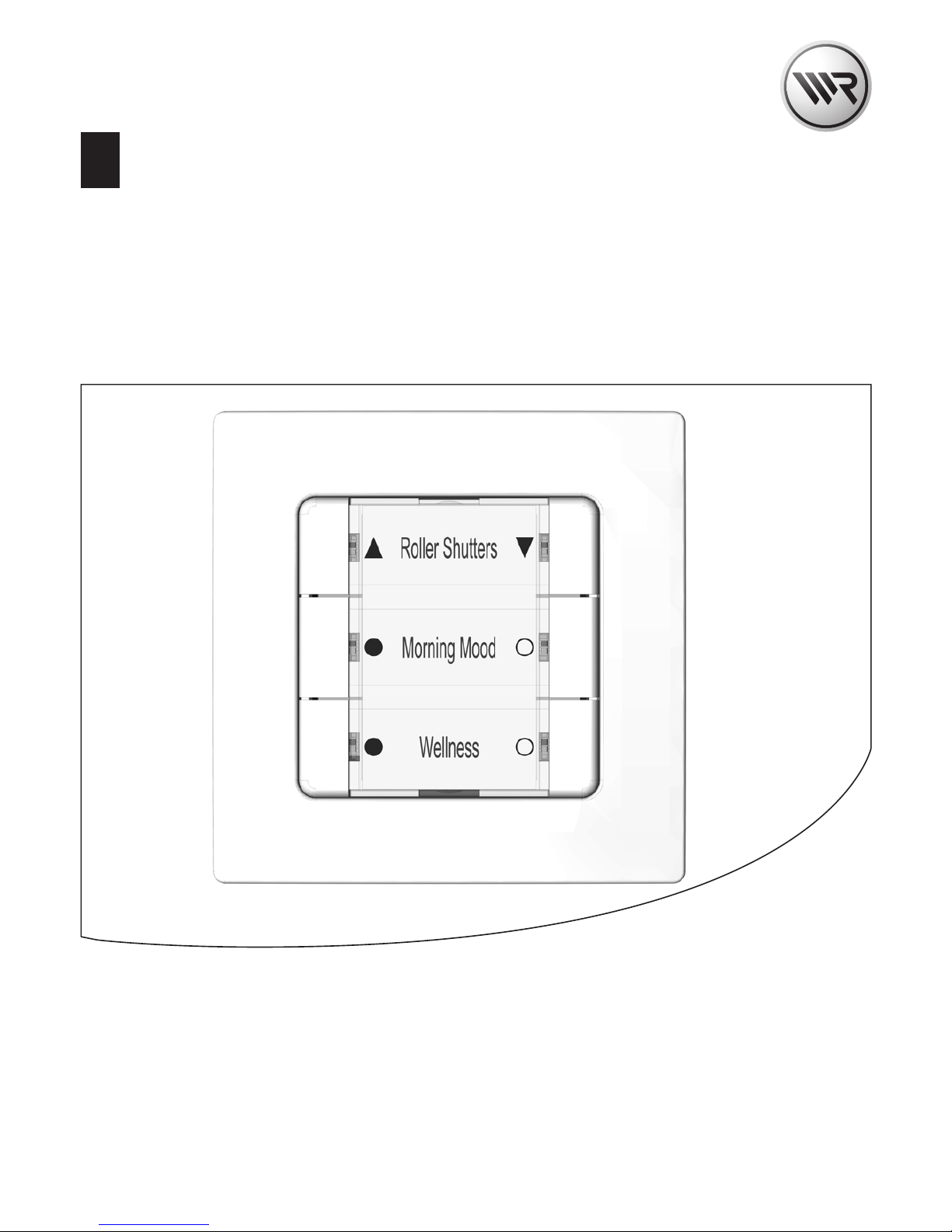
DuoFern Multiple Wall Controller 9494-2
Instruction manual for the electrical connection and for commissioning
Item no. 3250 19 72 / Type: 9494-2 (flush-mounted device for 230 V/ 50 Hz)
2
EN
i
Dear Customer,
With your purchase of a DuoFern Multiple Wall Controller, you
have chosen a quality product manufactured by RADEMACHER.
Thank you for the trust you have placed in us.
RADEMACHER products have been developed with the greatest
possible convenience in mind. Having applied uncompromising
quality standards and thorough testing, we are proud to be able
to present this innovative product to you.
It’s brought to you by all the highlyqualified personnel here at RADEMACHER.

3
EN
i
Contents
i Dear Customer, ...................................................................2
1. This manual... ......................................................................5
1.1 How to use this manual .....................................................................5
2. Hazard symbols ..................................................................6
2.1 Levels of danger and signal words .................................................6
2.2 Symbols and depictions used .......................................................... 7
2.3 Glossary - definition ............................................................................7
3. Included in delivery ...........................................................8
4. Front view of the operating unit .....................................9
5. Product description ........................................................ 10
5.1 Button functions ................................................................................ 12
5.2 Button combinations ....................................................................... 13
6. Technical specifications ................................................. 14
6.1 Conduct in the event of a power failure ................................... 16
7. Safety instructions .......................................................... 17
7.1 Intended use ....................................................................................... 18
7.2 Improper use ....................................................................................... 19
7.3 Required expert knowledge of the installer ............................ 19
8. Installation ........................................................................ 20
8.1 Printing the label insert ................................................................... 20
8.2 Selecting the suitable installation location ............................. 22
8.3 Connecting the DuoFern Multiple Wall
Controller 9494-2 ............................................................................... 22
8.4 Safety instructions for the electrical connection .......................23
8.5 Carrying out the Electrical Connection ..................................... 24
8.6 Connection of a lamp and push button .................................... 25
8.7 Connection Diagram with Changeover Switch ...................... 26
8.8 Installation after the electrical connection .............................. 27

4
EN
Contents
i
9. Commissioning ................................................................ 28
9.1 Removing the factory default reservation for
buttons 1 and 2 ................................................................................. 29
9.2 Logging on DuoFern Devices ....................................................... 30
9.3 Logging off DuoFern devices ........................................................ 31
9.4 Logging on to the HomePilot® ..................................................... 32
9.5 Clearing up the DuoFern network .............................................. 34
10. Activating the jog mode ................................................ 35
10.1 Operation in jog mode .................................................................... 36
11. Setting the lighting ......................................................... 37
12. Carrying out a hardware reset, e.g. if a unit fails .......... 38
13. Erase all settings, software reset .................................. 39
14. Dismantling ...................................................................... 40
15. Simplified EU Declaration of Conformity .................... 41
16. Warranty Terms and Conditions ................................... 42
17. Cut out label insert.......................................................... 43

5
EN
i
1. This manual...
...describes the electrical connection, installation, commissioning
and operation of your DuoFern Multiple Wall Controller 9494-2.
1.1 How to use this manual
◆ Before you begin, please read this manual through
completely and follow all the safety instructions.
◆ Please also read the instruction manuals of the logged on
DuoFern devices as well as of the respective connected
appliance.
◆ This manual is part of the product. Please store it in an
easily accessible place.
◆ When passing the DuoFern Multiple Wall Controller on to a
third party, this manual must be passed on as well.
◆ Damage resulting from non-compliance with these
instructions and safety instructions will void the warranty.
We assume no liability for any consequential damage.
i
6
EN
i
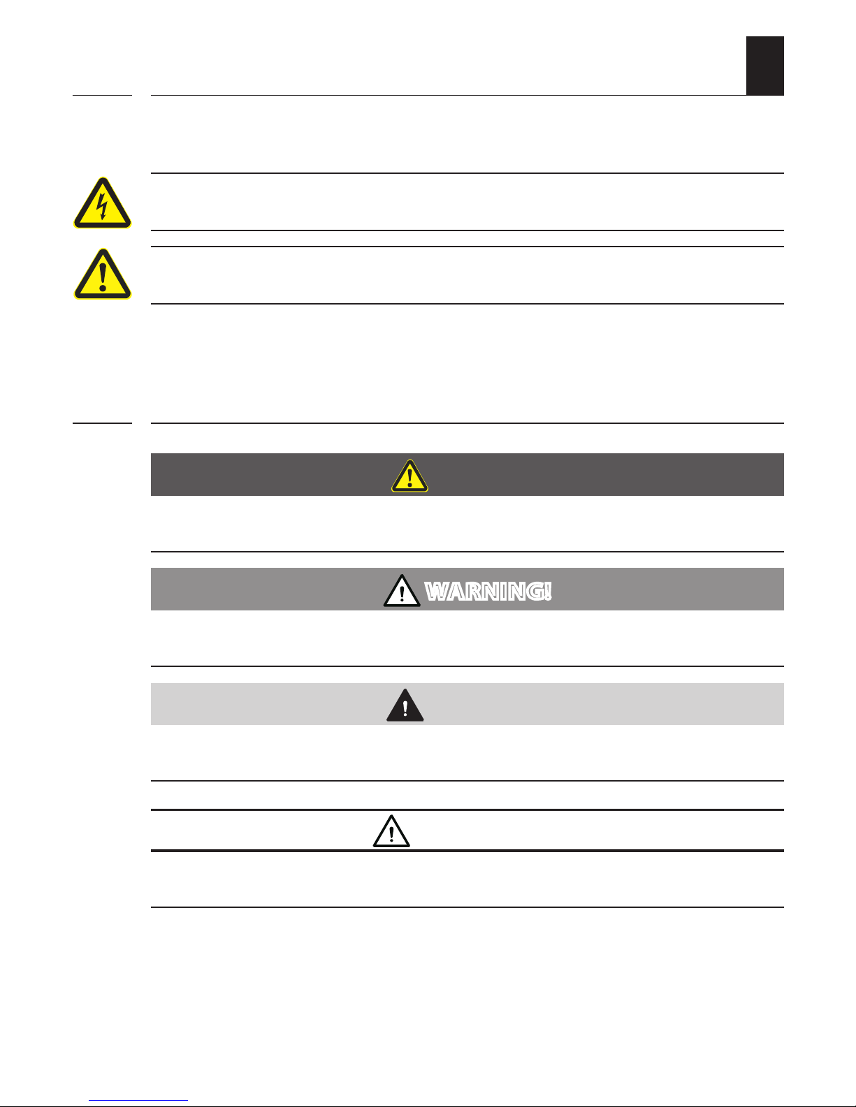
2. Hazard symbols
The following hazard symbols are used in this instruction manual:
Danger of fatal electric shock
Danger area / dangerous situation
2.1 Levels of danger and signal words
DANGER!
This hazard will lead to serious injury or death if not avoided.
WARNING!
This hazard may result in serious injury or death if not avoided.
CAUTION!
This hazard may result in minor or moderate injury if not avoided.
ATTENTION!
This hazard may lead to property damage.
i
7
EN
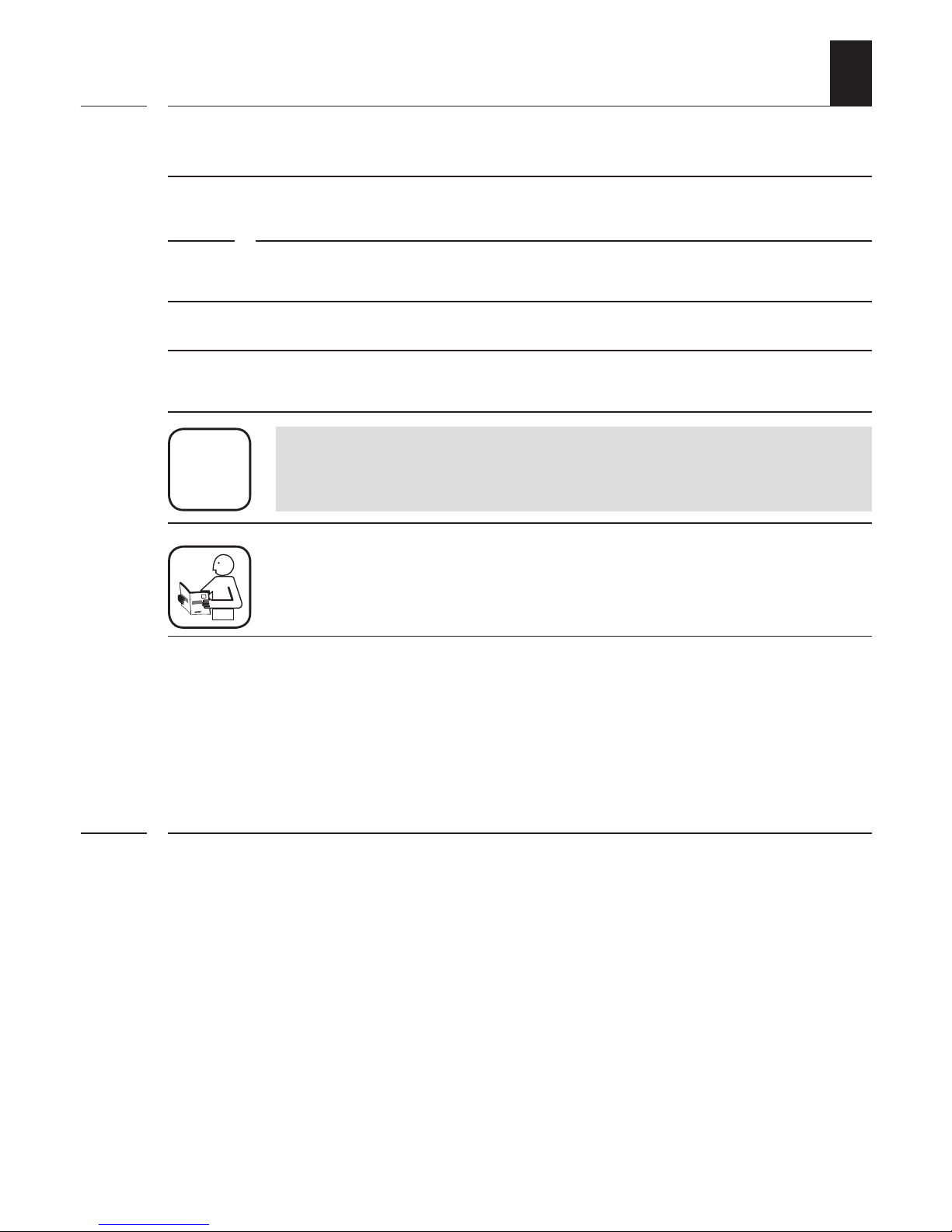
2.2 Symbols and depictions used
Depiction Description
1. Procedures
2.
◆ Itemisation
1) or a) Lists
i
further useful information
Please read the respective manual.
i
i
2.3 Glossary - definition
DuoFern
◆ RADEMACHER radio technology for controlling compatible
products.
HomePilot®
◆ The HomePilot® is a central controller unit for RADEMACHER
radio products.
8
EN
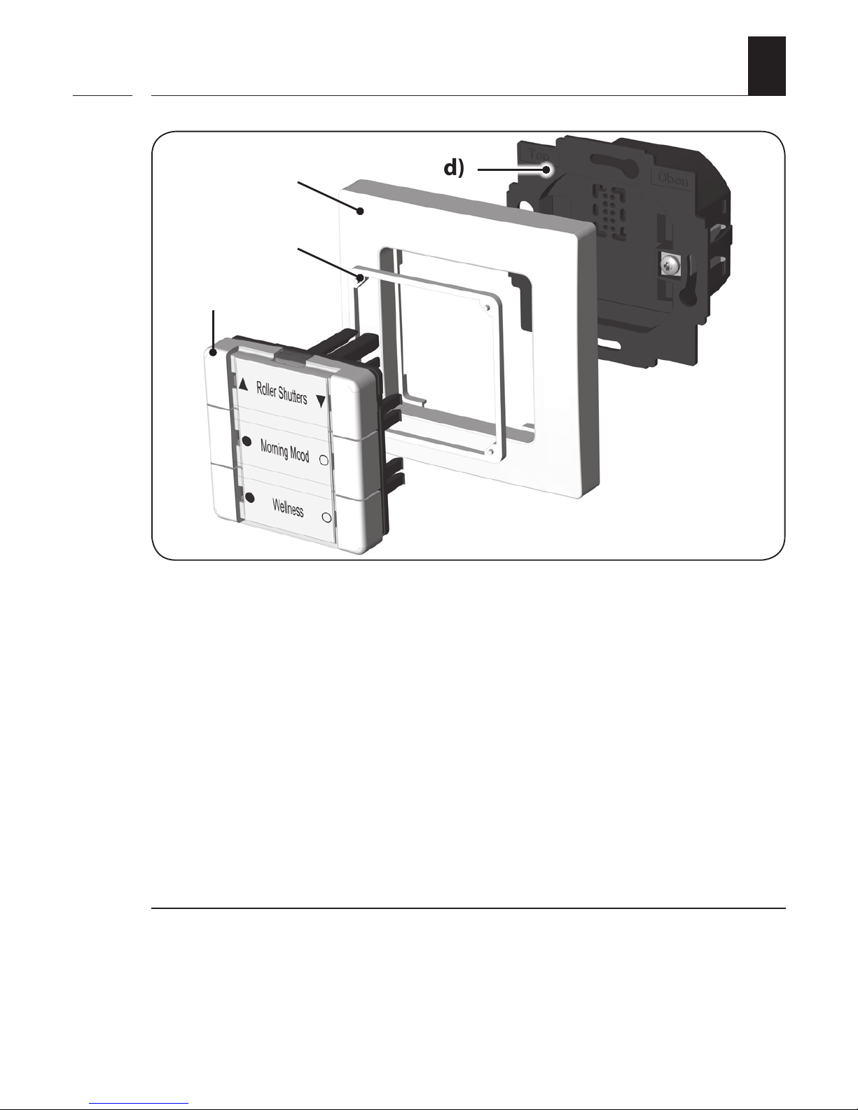
3. Included in delivery
a)
b)
d)
a) 1 x Operating unit (50 x 50 mm) with removable cover panel
for the label insert
b) 1 x Spacer frame
c) 1 x Frame
d) 1 x Installation housing
Not illustrated
e) 1 x Label insert, see page 20.
f) 1 x Instruction manual
After unpacking please check and compare...
... the contents of the package with those specified above.
i
c)
9
EN
i
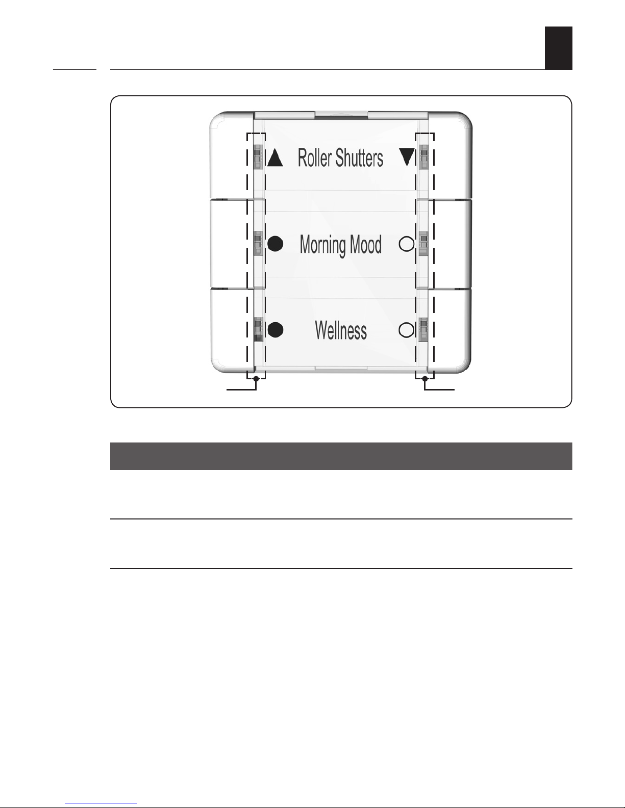
4. Front view of the operating unit
Symbol Description
T1 to T6 Buttons 1 to 6
LED 1 to LED 6 Each button has a red/white LED
T6
T2
T4
T5
T1
T3
LED 1/3/5 LED 2/4/6

10
EN
5. Product description
i
Function
The DuoFern Multiple Wall Controller serves to log on and control
various DuoFern devices. The six operating buttons can be used
to transmit the desired commands to the logged on DuoFern
devices. Six two-tone LEDs (red/white) provide information on
the respective status of the operation.
Max. number of DuoFern devices
A maximum of 8 DuoFern devices can be logged on per button
group. When logging on, the individual DuoFern devices are
automatically detected and recognised by the DuoFern Multiple
Wall Controller.
Jog mode
To control Venetian blinds with slats, the DuoFern Multiple Wall
Controller can be switched to jog mode.
White LEDs used to display the status and for lighting
The white LEDs of the DuoFern Multiple Wall Controller can
additionally be used to display the status as well as for lighting.
If required, the brightness of the white LEDs can also be
adjusted with three different settings.

11
EN
5. Product description
Relay output [ L‘ ] and external control input [ Ext. ]
In addition, the DuoFern Multiple Wall Controller 9494-2 is
equipped with
◆ a relay output [ L‘ ] for the connection * of an electrical
appliance: e.g. lighting when replacing a light switch.
◆ an external control input [ Ext. ] for the connection * of
an additional external switch or button for the electrical
appliance.
* electrical connection, see page 25.
i
Buttons 1 and 2 are, ex works, reserved for the relay
output [ L‘ ] and to control DuoFern Universal
actuators.
If required, this factory setting can be removed,
see page 29.
i
12
EN
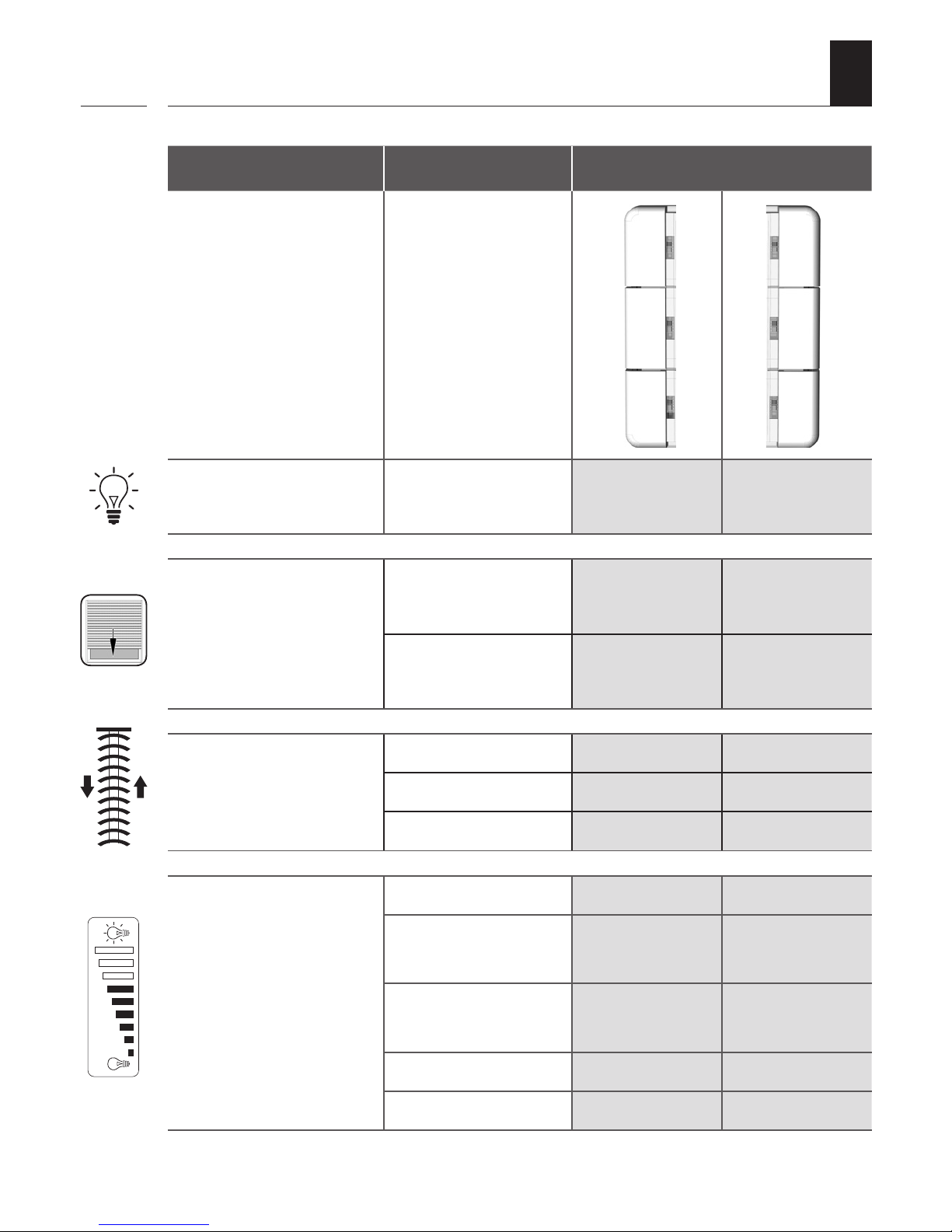
i
Controller Design Function
Activate or deactivate
the light or appliance
1 x tap ON OFF
Control roller shutters /
Venetian blinds
1 x tap UP DOWN
tap again STOP STOP
Roller shutters /
Venetian blinds in
jog mode
1 x tap briefly UP briefly DOWN
1 x long UP DOWN
tap again STOP STOP
Dim light or save
interim values
1 x tap 0 to 100 % 100 % to 0
2 x tap
go directly to
100 %
go directly to 0
1 x tap in opposite
direction
e.g. save 75 % e.g. save 45 %
Press and hold 0 to 100 % 100 % to 0
release e.g. save 75 % e.g. save 45 %
5.1 Button functions
T1
T2
T3 T4
T5 T6
0 %
100 %

13
EN
i
5.2 Button combinations
Activate the registering
mode, see page 30.
Activate the log-off mode,
see page 31.
Clear the DuoFern
network, see page 34.
Activate the jog mode,
see page 35.
Set lighting,
see page 37.
1 sec.
1 sec.
5 sec. 1 sec.
Software reset,
see page 39.
5 sec.
14
EN
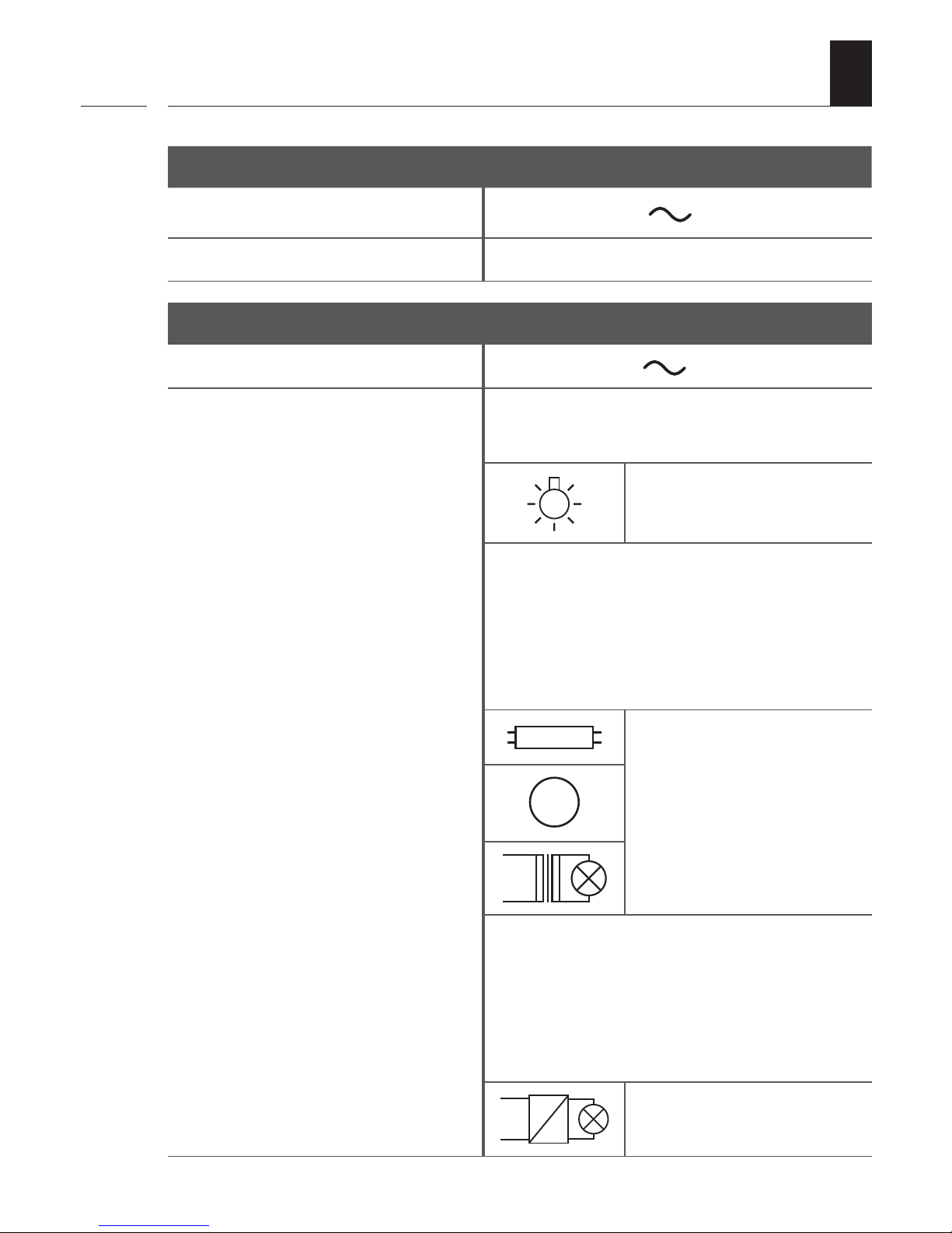
6. Technical specifications
i
Mains supply [ L / N ]
Mains supply voltage: 230 V / 50 Hz
Consumption: Standby: < 0.6 W
Connection [ L‘ and L / N ]
Switching voltage: 230 V / 50 Hz
Maximum switching
capacity:
ohmic load, e.g. bulbs
12 A (µ) (Type 1B)
inductive loads such as:
fluorescent lamps, drives,
iron core transformers, e.g. for
extra-low voltage bulbs such as
halogen bulbs
6 A (µ) (Type 1B)
M
capacitive loads such as:
electronic transformers, AC/DC
transformer, e.g. for extra-low
voltage lamps such as halogen
lamps, LEDs, etc.
6 A (µ) (Type 1B)

15
EN
Control input [Ext. ]
for an external, manual switch / push button on site
Input voltage: 230 V
Maximum length of the
control cable:
10 m
Improper use can lead to serious injuries or property damage.
◆ Due to the small contact distance (µ), not suitable for
disconnecting.
◆ The DuoFern Multiple Wall Controller 9494-2 should not be
used for an electrically safe disconnection of the connected
appliances.
General information
Permissible ambient temperature:
0 °C to 40 °C
Protection class: II (only for use in dry rooms)
Dimensions (W x H x D): 50 x 50 x 12 mm (operating unit)
Installation depth 32 mm (installation housing)
Connecting terminals:
Screw terminals for max.
1.5 mm
2
cable cross-section
6. Technical specifications
i

16
EN
DuoFern radio technology
Transmission frequency: 434.5 MHz
Transmission power: max. 10 mW
Range:
indoors: approx. 30 m *
outdoors: approx. 100 m
* depending on the building structure
Max. number of DuoFern
devices:
8 per button group
24 in total
Factory settings
DuoFern devices: none
Jog mode: deactivated, for all groups
Allocation of switch relay: Buttons 1 and 2
Lighting: Off
6. Technical specifications
i
6.1 Conduct in the event of a power failure
Data retention following a power failure
All settings remain permanently saved. Data is not lost even
after a longer power failure.
i

17
EN
i
The use of defective equipment can lead to personal injury
and damage to property (electric shocks / short circuiting).
◆ Never use defective or damaged equipment.
◆ Check that the DuoFern Multiple Wall Controller is intact.
◆ Consult our customer service department in the event that
you discover damage, see page 44.
There is a risk of fatal electric shock when touching
electrical components of the DuoFern Multiple Wall
Controller 9494-2.
◆ Switch off the mains power before removing the cover
panel.
◆ The DuoFern Multiple Wall Controller 9494-2 should not be
operated without the cover panel and frame.
◆ Assemble all the components of the operating unit before
inserting it into the installation housing.
Short-circuiting, caused when the DuoFern Multiple Wall
Controller 9494-2 is overloaded, poses a danger to life.
◆ The maximum switching capacity must not be exceeded.
◆ Only use the control output [ L‘ ] for connecting and
controlling electrical appliances (e.g. lighting etc.) within
the permissible load limits, see “Technical Specifications” on
page 14 .
7. Safety instructions

18
EN
7.1 Intended use
Only use the DuoFern Multiple Wall Controller to log on and
control DuoFern devices.
Operating conditions
◆ The associated tubular motor must be fitted with a
mechanical or electronic end position switch.
◆ Only use the DuoFern Multiple wlal Controller 9494-2 in
dry rooms.
◆ For the electrical connection of the DuoFern Multiple Wall
Controller 9494-2, a 230 V/50 Hz power supply, together
with a site-provided disconnecting device (fuse), must be
available at the installation location.
◆ The installation and operation of the radio systems is only
permitted for those systems and devices where a malfunction
in the transmitter or receiver would not cause a danger to
personnel or property or where this risk is already covered
by other safety equipment.
i

19
EN
i
Using the DuoFern Multiple Wall Controller for any other purpose
than previously mentioned is not permissible.
Improper use can lead to serious injuries or property
damage.
◆ Never use the radio system (e.g. DuoFern radio system) and its
components for the remote control of appliances and systems
with increased safety-relevant requirements or where there is
an accident risk. Such applications require additional safety
equipment. Observe the respective statutory regulations for
the installation of such systems.
◆ The DuoFern Multiple Wall Controller 9494-2 should not be
used for an electrically safe disconnection of the connected
appliances.
There is a risk to life caused through short circuiting and
electric shocks if the DuoFern Multiple Wall Controller 9494-2
is used outside or in damp rooms.
◆ Do not install and use the DuoFern Multiple Wall Controller
9494-2 outdoors or in damp rooms.
7.2 Improper use
i
The electrical connection, installation and commissioning of the
DuoFern Multiple Wall Controller 9494-2 must only be carried
out by a qualified electrician in accordance with the instructions
in this manual.
7.3 Required expert knowledge of the installer

20
EN
i
8. Installation
i
The DuoFern Multiple Wall Controller 9494-2 is intended for
flush mounting. We recommend installation in a deep 58 mm
flush-mounted box or in an electronic socket.
The label insert must be printed and the electrical connection
must be carried out prior to installation.
8.1 Printing the label insert
DANGER!
There is a risk of fatal electric shock when touching
electrical components of the DuoFern Multiple Wall
Controller 9494-2.
◆ Switch off the mains power before removing the cover
panel.
◆ The DuoFern Multiple Wall Controller 9494-2 should not be
operated without the cover panel and frame.
◆ Assemble all the components of the operating unit before
inserting it into the installation housing.

21
EN
8.1 Printing the label insert
i
i
Templates can be found on our website: here,
individual label inserts can be created and printed.
www.rademacher.de
* Should you have no access to a laser printer, please alterna-
tively use standard printing paper for the label insert.
1. The provided label insert can be printed with the application
specified by you. Please only use a laser printer for printing. *
2. Lift the transparent cover panel from the operating panel and
insert the printed paper into the cover panel. Next, press the
cover panel on to the operating unit until it locks in place.

22
EN
8.2 Selecting the suitable installation location
i
8.3 Connecting the DuoFern Multiple Wall Controller
9494-2
Avoid installation near disturbing sources
i
Radio systems that transmit on the same frequency
can cause interference.
◆ Do not install the DuoFern Multiple Wall
Controller in the proximity of powerful radio
systems.
◆ In order to ensure optimal operation, the DuoFern
Multiple Wall Controller should not be installed
on a metallic base or near metal objects.
Prior to the electrical connection, check that the voltage / frequency
on the type plate corresponds to that of the local mains supply.
Read the specifications relating to the electrical
connection detailed in the instruction manual of the
electrical appliance used.
i
Length of insulation stripped:
6 mm
All leads must be stripped to 6 mm.

23
EN
i
8.4 Safety instructions for the electrical connection
DANGER!
There is a risk of fatal electric shock when touching
electrical components.
◆ All connection and installation work must only be carried
out in a de-energised state.
◆ Disconnect all phases of the mains power cable and secure
it to prevent any reconnection.
◆ Check that the system is de-energised.
WARNING!
Using an incorrect installation housing can lead to personal
injury and damage to property (electric shocks / short
circuiting).
◆ Only use the installation housing provided to connect and
install the DuoFern Multiple Wall Controller 9494-2.
◆ Installation housings of other RADEMACHER products are
not compatible.
Connection instructions when using an external switch/
push button
◆ When using the control input [Ext. ], you must connect the
external switches / push buttons and the DuoFern Multiple
Wall Controller 9494-2 to the same phase [L].
◆ The maximum length of lead to connect an external switch/
push button must not exceed 10 m.

24
EN
i
8.5 Carrying out the Electrical Connection
1. Ensure the mains is disconnected and check whether the mains
power cables are current-free.
2. Securely lay the connecting cables right into the flush-mounted
box.
3. Remove the insulation on all leads down to 6 mm in length and
connect them according to the following connection diagram.
4. After the electrical connection, the installation of the
installation housing into the flush-mounted box and the
installation of the operating unit are carried out, see page 27.

25
EN
NL‘ N L L Ext.
230 V / 50 Hz
L
N
PE
NL
i
8.6 Connection of a lamp and push button
i
The additional connection terminals [ N ] and [ L ] are
solely intended for wiring the connected electrical
consumers and/or an external switch / push button.
◆ Do not use the connection terminals [N] and [L]
for further indoor installations.
Lamp
External switch or
push button (optional)

26
EN
NL‘ N L L Ext.
230 V / 50 Hz
L
N
PE
NL
i
8.7 Connection Diagram with Changeover Switch
Lamp
* Changeover switch (cross connection also possible)
*
i
The additional connection terminals [ N ] and [ L ] are
solely intended for wiring the connected electrical
consumers and/or an external switch / push button.
◆ Do not use the connection terminals [N] and [L]
for further indoor installations.

27
EN
i
8.8 Installation after the electrical connection
1. Insert the installation housing into the flush-mounted box and
fasten it with the screws of the claw fasteners.
2. Place the frame on the installation housing and put the spacer
frame into the frame.
3. Then carefully insert the operating unit into the installation
housing .
4. Switch on the mains power supply again.
5. The lighting will turn on and the LEDs indicate the operational
readiness by means of a running (continuous) light.

28
EN
9. Commissioning
i
Information for logging on DuoFern devices
i
Only DuoFern devices or devices within the same class/
category can be allocated to a specific button group.
When logging on, the individual DuoFern devices
are automatically detected by the DuoFern Multiple
Wall Controller, and the available button groups are
displayed.
Please read the instruction manual for the respective
DuoFern device.
i
Buttons 1 and 2 are, ex works, reserved for the relay
output [ L‘ ] and to control DuoFern Universal
actuators.
If required, this factory setting can be removed,
see page 29.
Controlling the relay output [ L‘ ] with a DuoFern transmitter
If a DuoFern transmitter is logged on to the DuoFern Multiple
Wall Controller 9494-2, the relay output [ L‘ ] can be switched
with this.
Max. number of DuoFern devices
You can log a maximum of 8 DuoFern devices on to each button
group.

29
EN
9.1 Removing the factory default reservation for
buttons 1 and 2
i
i
To remove the reservation, no DuoFern devices
should yet be logged on to buttons 1 and 2.
Should DuoFern devices already be logged on, a
software rest must be carried out first, see page 39.
Morning Mood
Wellness
Roller shutters
Removing the factory default reservation for buttons 1 and 2
1. Log off all DuoFern devices from buttons 1 and 2,
see information above.
2. 10 sec. Press and hold the button 2 for approx.
10 seconds.
LEDs 1 and 2 will light up white.
Restoring the factory default reservation for buttons 1 and 2
1. Repeat steps 1 and 2 above.
The LEDs 1 and 2 will light up red as soon as the reservation of
the buttons is restored.
i
The relay output [ L‘ ] can still
be operated via a DuoFern
transmitter after the
disconnection.

30
EN
9.2 Logging on DuoFern Devices
1. Switch the desired DuoFern device to the registering mode (please
refer to the relevant instruction manual).
2. 1 sec. Activate the registering mode of the
DuoFern Multiple Wall Controller.
Simultaneously press and hold the
buttons 1 and 2 for 1 second.
LEDs 1 and 2 will flash white.
120 sec. The registering mode remains active for
approx. 120 seconds.
3. After successfully logging on, the LEDs of the remaining available
buttons will light up white.
4. Tap on the desired available button group to allocate the new
DuoFern device to this button group.
5. Log-on the next DuoFern device.
i
Pay attention to the LEDs
All LEDs will light up red, one after the other, if the log-on was
unsuccessful. For example, if...
◆ 8 DuoFern devices are already logged on to a button group.
◆ an unsuitable device is logged on.
Morning Mood
Wellness
Roller shutters

31
EN
9.3 Logging off DuoFern devices
1. Switch the desired DuoFern device to the log-off mode
(please refer to the relevant instruction manual).
2. Activate the log-off mode on the
DuoFern Multiple Wall Controller.
Simultaneously press and hold the
buttons 5 and 6 for 1 second.
LEDs 5 and 6 will flash red.
120 sec. The log-off mode remains active for
approx. 120 seconds.
3. After successfully logging off, the LED of the relevant button will
light up white.
i
Morning Mood
Wellness
Roller shutters
1 sec.

32
EN
9.4 Logging on to the HomePilot®
i
In combination with the HomePilot®, all 6 buttons of the DuoFern
Multiple Wall Controller can be used to individually trigger scenes.
To do so, it must first be logged on to the HomePilot®.
1. Open the user interface of the HomePilot® and click left on the
button [configuration] and then on [register device].

33
EN
9.4 Logging on to the HomePilot®
i
2. 1 sec. Simultaneously press and hold the
buttons 1 and 2 for 1 second to activate
the registering mode of the DuoFern
Multiple Wall Controller.
4. Click on the desired device and assign an individual name,
if required. In addition, a graphic symbol can be selected.
5. Save the setting. The DuoFern Multiple Wall Controller is then
listed on the left under "devices" and "transmitters" and can be
used immediately.
Morning Mood
Wellness
Roller shutters
3. Two devices are displayed in the left table after successfully
logging on:
◆ a transmitter DuoFern Multiple Wall Controller
◆ an actuator DuoFern Multiple Wall Controller

34
EN
9.5 Clearing up the DuoFern network
This function enables you to log off all DuoFern devices from the
DuoFern Multiple Wall Controller that are no longer accessible
via radio.
i
Not all battery-operated DuoFern devices can be
logged off in this way.
A software reset must be carried out in order to logout
and delete all DuoFern devices, see page 39.
1. 5 sec. Activate the clear up.
Simultaneously press and hold the
buttons 1 and 2 for 5 seconds.
During the clear up period, LEDs 1 + 2
will flash red.
2. Once the clear up process has been successfully completed,
LEDs 1 + 2 will briefly light up white.
Cancelling the clear up function
You can cancel the clearing process at any time by briefly
pressing any random button.
i
Morning Mood
Wellness
Roller shutters

35
EN
10. Activating the jog mode
In the jog mode, the DuoFern Multiple Wall Controller can be
used, e.g. to control Venetian blinds.
i
1. 1 sec. Activate the switching mode.
Simultaneously press and hold the
buttons 2 and 5 for 1 second.
LEDs 2 and 5 will flash red.
2. If there is a switching mode for one of the button groups, the
according LEDs 1 to 6 will light up white.
left LED white jog mode is deactivated
right LED white jog mode is activated
5 sec. Attention! The switching mode only
remains active for approx. 5 seconds.
Activate the jog mode for one button group
Morning Mood
Wellness
Roller shutters

36
EN
10.1 Operation in jog mode
Tilting the slats
Briefly tapping the operating buttons enables Venetian blinds
slats to be conveniently configured.
Driving the slats into the end position
Press the operating button longer to drive the Venetian blinds
into the end position. The drive can be stopped again by briefly
tapping the button again, see page 12 "Button functions".
i

37
EN
11. Setting the lighting
i
The DuoFern Multiple Wall Controller 9494-2 has permanent lighting that has four different settings (Off + 3 levels of brightness).
Function when on standby
The lighting will shine permanently in the set brightness level.
5 sec. Attention! The setting mode
only remains active for approx.
5 seconds.
1. 1 sec. Activate the setting mode.
Simultaneously press and hold the
buttons 2 and 5 for 1 second.
LEDs 1 and 6 will flash red.
2. Set the brightness level for the standby mode.
Brighter
Darker
Morning Mood
Wellness
Roller shutters
Roller shutters
Morning Mood
Wellness
Roller shutters

38
EN
12. Carrying out a hardware reset, e.g. if a unit fails
We recommend resetting the hardware if the DuoFern Multiple
Wall Controller 9494-2 fails.
i
All settings remain unaltered when the hardware
is reset.
i
1. Carefully pull the operating unit out of the installation housing.
2. Wait approx. 5 seconds and then carefully reinsert the operating
unit into the installation housing.
3. Subsequently check that the DuoFern Multiple Wall Controller
9494-2 is functioning correctly.
4. If the DuoFern Multiple Wall Controller 9494-2 is still not reacting,
carry out a software reset (see page 39) and test the DuoFern
Multiple Wall Controller 9494-2 with the factory settings.

39
EN
A software reset must be carried out to reset the DuoFern
Multiple Wall Controller to the original default condition as
when supplied.
13. Erase all settings, software reset
1. Press and hold buttons 5 and 6
simultaneously until all LEDs
continuously light up red.
i
Morning Mood
Wellness
Roller shutters
2. All settings have been erased and reset to the default factory
settings. All of the registered DuoFern devices are automatically
logged-off.

40
EN
14. Dismantling
i
1. Carry out a software reset (see page 39) to log off all DuoFern
devices from the DuoFern Multiple Wall Controller.
2. Ensure the mains are current-free. Secure it from restarting and
check that the system is de-energised.
3. Carefully pull the operating unit and then the frame out of the
installation housing.
4. Release the claw fasteners of the installation housing and pull it
out of the flush-mounted box.
5. Disconnect the connecting cable from the installation housing.
6. Secure the connection point against restarting and the connecting
cable from unintentional contact.
DANGER!
There is a risk of fatal electric shock when touching
electrical components.
◆ Disconnect all phases of the mains power cable and secure
it to prevent any reconnection. Check that the system is
de-energised.

41
EN
15. Simplified EU Declaration of Conformity
i
RADEMACHER Geräte-Elektronik GmbH hereby declares that
the DuoFern Multiple Wall Controller 9494-2 complies with the
Directive 2014/53/EU (Radio Equipment Directive).
The full text of the declaration of conformity is available at the
following website:
www.rademacher.de/ce

42
EN
i
16. Warranty Terms and Conditions
RADEMACHER Geräte-Elektronik GmbH shall provide a
24-month warranty for new systems that have been installed in
compliance with the installation instructions. All construction
faults, material defects and manufacturing defects shall be
covered by the warranty.
Your statutory warranty claims shall remain unaffected by this
warranty.
The following shall not be covered by the warranty:
◆ Incorrect fitting or installation
◆ Non-observance of the installation and operating instructions
◆ Improper operation or wear and tear
◆ External influences, such as impacts, knocks or weathering
◆ Repairs and modifications by third parties, unauthorised
persons
◆ Use of unsuitable accessories
◆ Damage caused by unacceptable excess voltages
(e.g. lightning)
◆ Operational malfunctions caused by radio frequency
overlapping and other such radio interference
A prerequisite for the warranty is that the new device must have
been purchased from one of our approved specialist retailers.
Proof of this must be provided by presenting a copy of the bill.
RADEMACHER shall remedy any defects that occur within the
warranty period free of charge either by repair or replacement
of the affected parts or by supplying a new replacement unit or
one to the same value. There shall be no general extension of the
original warranty period by delivery of a replacement or by repair
as per the terms of the warranty.

43
EN
✂
17. Cut out label insert
30 mm
47 mm
i

RADEMACHER
Geräte-Elektronik GmbH
Buschkamp 7
46414 Rhede (Germany)
info@rademacher.de
www.rademacher.de
Service:
Hotline 01807 933-171*
Fax +49 2872 933-253
service@rademacher.de
* 30 seconds free of charge, subsequently
14 cents / minute from German fixed line
networks and max. 42 cents / minute from
German cellular networks.
Subject to technical modifications, misprints and errors excepted. Illustrations not binding.
 Loading...