

VBD 520-2 (05.13)
Item no. 3481 00 60
EN
Operating Manual
DuoFern Central Operating Unit
2
EN
i
By purchasing the DuoFern central operating unit you have chosen a quality product
manufactured by RADEMACHER. Thank you for the trust you have placed in us.
This product has been developed with the greatest possible convenience in mind.
The intuitive menu navigation make it considerably easier to use. Having applied
uncompromising quality standards, and carried out thorough testing, we are proud
to be able to present you with this innovative product.
It’s brought to you by all the highly-qualified personnel
here at RADEMACHER.
Dear Customer,
These instructions...
CE Mark and Conformity
...describe how to use the DuoFern central operating unit.
Before you begin, please read these instructions through completely and follow all
the safety instructions.
Please store these instructions in a safe place and pass them on to any future owners.
Damage resulting from non-compliance with these instructions and safety instructions
will void the guarantee. We assume no liability for any consequential damage.
The DuoFern central operating unit (item no. 3481 00 60) complies with the requirements
of the current European and national directives. The conformity has been verified
and the corresponding declarations and documentation are available on file at the
manufacturer’s premises.
i
i

3
EN
i
Contents
Dear Customer, .........................................2
These instructions... .................................. 2
CE Mark and Conformity ............................ 2
Key to symbols .........................................4
General view ............................................5
Functional description ..............................6
The „WR ConfigTool“ PC software ...............7
Functions for DuoFern actuators ................7
Commissioning the central operating unit .. 8
The control keys ......................................10
The various menu views .......................... 14
Normal view ........................................... 15
The main menu.......................................17
The system settings menu
...............18
Examples of application .......................... 19
– Connecting a DuoFern actuator. ....... 20
– Connecting a DuoFern actuator
via a radio code. .............................. 24
– Configuring switching times for a
group .............................................26
– Setting the position of the sun .........28
Automatic functions in the main menu ....30
Menu overview / main menu ................... 31
Main menu ............................................. 32
System settings ...................................... 43
– Menu overview /
1. 1 Actuators .........44
– Menu overview /
1.2 Groups ............. 49
– Menu overview / 1
.
3 Central
operating unit .................................52
– Menu overview / 1
.
4 Sensors ............ 57
– Menu overview / 2 Radio settings ...58
Technical Specifications ..........................60
Battery replacement ............................... 60
Time zone table ...................................... 61
Suggested names for groups and
members ................................................63
Menu overview .......................................64
CE Mark and EC Conformity ..................... 66
Warranty conditions ...............................67
4
EN
i
Key to symbols
This concerns your safety
Please pay particular attention and carefully
follow all instructions marked with this symbol.
NOTE / IMPORTANT / WARNING
Safety instructions to draw your attention to additional information that is important
for trouble-free operation.
Please read the operating instructions for the external device (e.g. a DuoFern actuator)
described at this point.
Proper use
Only use the DuoFern central operating unit ...
... and the associated components of the DuoFern radio system (actuators, sensors,
etc.) for remotely controlling the following equipment:
◆ Roller shutters
◆ Venetian blinds
◆ Awnings
◆ Electrical appliances (e.g. lamps)
Operating conditions
◆ The installation and operation of the DuoFern radio system and its components is
only permitted for those systems and devices where a malfunction in the transmitter
or receiver would not cause a danger to personnel or property or where this risk
is already covered by other safety equipment.
◆ Only use the DuoFern central operating unit in dry rooms.
Improper use
Never use the DuoFern central operating unit to...
...remote control devices and systems with increased safety-relevant requirements
or where there is an increased risk of accidents. This shall require additional safety
equipment. Observe the respective statutory regulations for the installation of such
systems.
i
i
5
EN
i
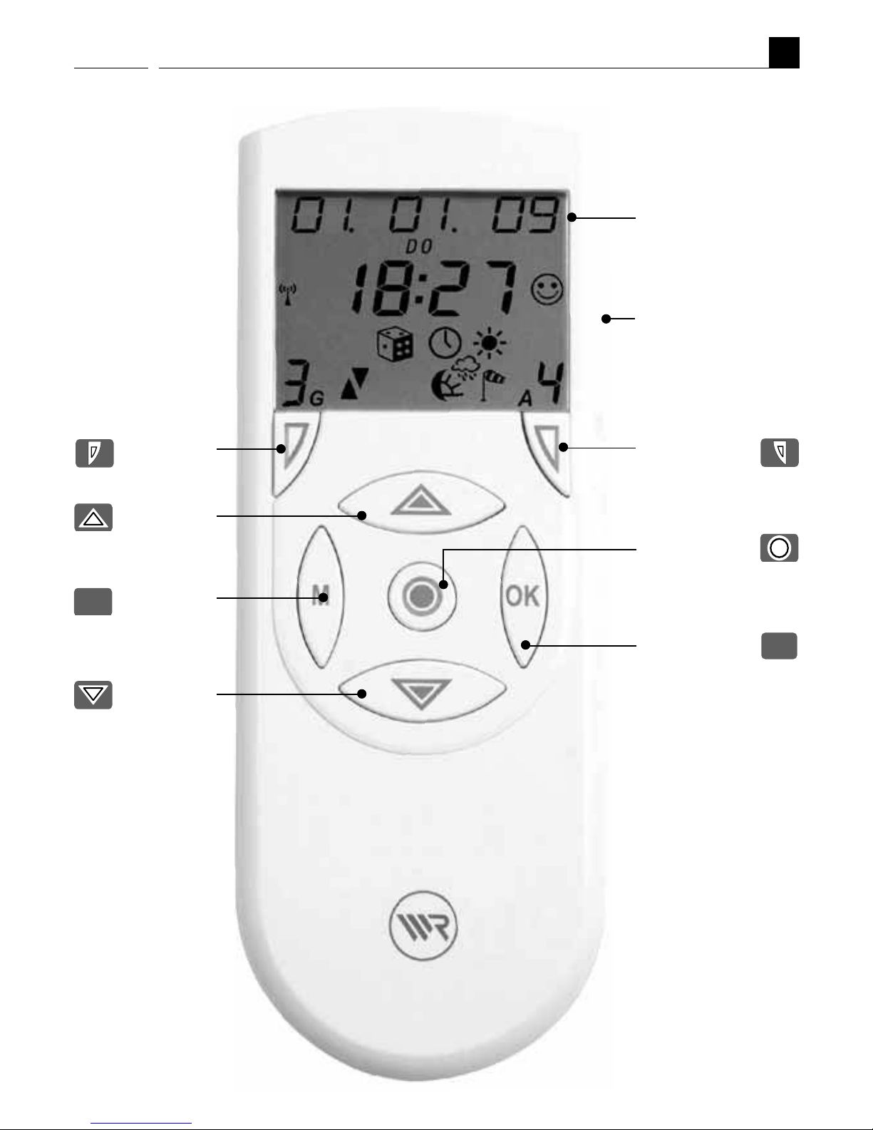
General view
Display
Member
key
Group
key
Function
key
Function
key
Menu
key
OK key
Function
key
Battery
compartment on
the rear side (incl.
USB port
OK
M

6
EN
i
Functional description
The DuoFern central operating unit is the universal input device for the DuoFern radio
system. The DuoFern central operating unit makes it possible to configure the functions
you require (e.g. connecting and disconnecting actuators and sensors / creating groups
/ automatic switching times, etc.) The settings are transmitted wirelessly to all of the
actuators and connected end units (appliances).
The actuators/sensors must be connected to the central operating unit.
Each DuoFern actuator/sensor has to be assigned to the central operating unit for
your settings and manual switching commands to be executed.
Explanation of terms
The following terms are used in this manual: actuators/members and end units.
Two members or two end units can be controlled by a two-channel actuator after
connection to the central operating unit.
Creating groups
You can collate the logged-on end units together into groups.
9
9
81
Maximum number of groups and members
Groups:
Members per group:
End units
(appliances connected to the actuators)
The following rules apply:
◆ An end unit can only be placed into a group as a member once.
◆ An end unit can be placed in numerous groups.
◆ The central operating unit always suggests the next free group slot.
This serves to avoid unintentional changes.
You can assign a name for all end units and groups
An individual name can be assigned to all end units and groups in order to facilitate a
better overview (e.g. lounge, kitchen, etc.). A table with preprogrammed suggested
names is included on page 63.
7
EN
i
i
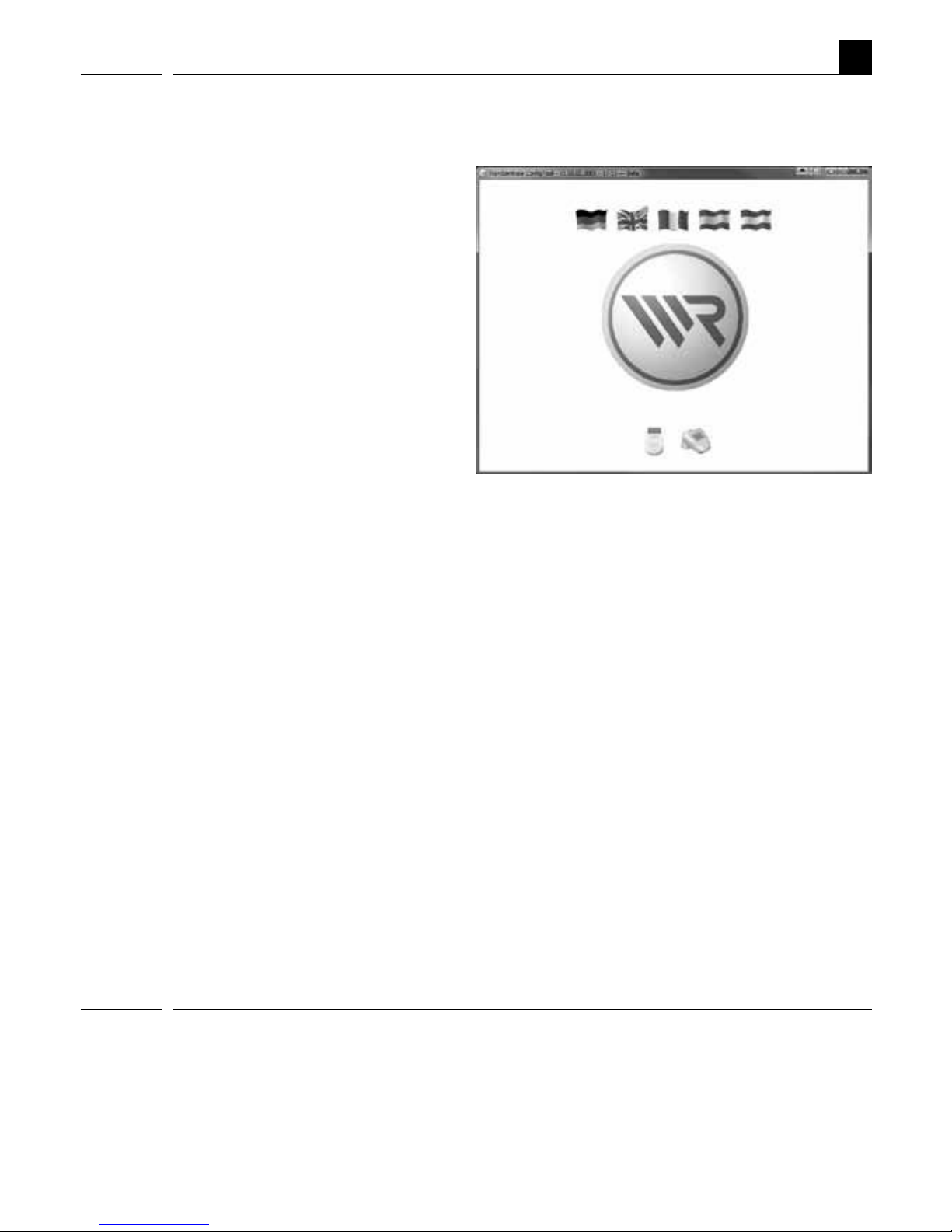
The „WR ConfigTool“ PC software
Alternative function input using the PC software "WR ConfigTool"
Alternately it is possible to set all
functions quickly and clearly on a
computer (which must have a USB
port) using the configuration software
and then to transfer the settings to
the central operating unit.
The "WR ConfigTool" PC software offers the following options:
◆ Convenient configuration via computer.
◆ Assignment of individual names for groups and members.
◆ Backup your settings.
NOTE
◆ You can download the latest version of the configuration software at any time
from the download area on our website (www.rademacher.de/download).
◆ The USB port is located under the battery compartment cover.
◆ It is not possible to directly control end units with WR ConfigTool.
Functions for DuoFern actuators
An overview of all central operating unit functions which can be configured for use with
the individual DuoFern actuators can be found on our website (rademacher.de/duofern).

8
EN
i
Commissioning the central operating unit
Insert batteries (pay attention to the polarity)
Insert the batteries into the battery compartment at the rear of the central operating
unit. Please pay attention to the correct polarity when inserting the batteries.
Only use the following battery type: 3 x 1.5 V type AAA (Micro).
NOTE
The central operating unit will not work if the batteries are inserted incorrectly.
Incorrectly inserted batteries can cause damage to the central operating unit.
Setting the date and time
After changing the batteries, you will be prompted to set the current time and date;
see page 53. If you have DCF signal reception at the site of operation, you can ignore
this prompt. Pressing the
OK
-key multiple times enables you to quit setting mode.
9
EN
i
Check DCF signal reception
The central operating unit is equipped with a DCF radio timer. The current date and
time will be set automatically once the DCF signal is received.
The DCF signal scan begins:
◆ as soon as the batteries are inserted (commissioning).
◆ the next day at 03:01 AM, in the event that no DCF signal was available at the
time of commissioning.
◆ every Sunday at 03:01 AM.
NOTE
Reception of a valid signal can take up to 5 minutes.
Under what circumstances is it possible that no valid /
correct DCF signal is received?
◆ If the place of use of the central operating unit is more than 1500 km
from Frankfurt am Main / Germany.
◆ If you are operating the central operating unit in another time zone.
◆ If building conditions restrict reception.
◆ If DCF reception is deactivated.
What can I do if the DCF signal is not detected?
◆ Activate the DCF clock, see page 53.
◆ Enter the current time and date manually; see page 53.
Observe the radio clock icon on the display:
Status Message
A DCF signal is being scanned for. The icon flashes.
A DCF signal has been received. The icon lights up.
No DCF signal has been received. The icon remains off.
DCF reception is deactivated. The icon remains off.
Commissioning the central operating unit

10
EN
i
The control keys
The controls keys can be used to navigate within the menus and sub-menus of the
central operating unit as well as to carry out all of the required programming settings.
The various menu views are described from page 14 on.
The following section serves to briefly describe the individual keys and their functions.
A precise functional description shall follow in the latter part of this manual, as part
of the description for the individual settings.
NOTE
For space reasons, the keys are depicted in all of the chapters with substitute icons
instead of the original depiction. Observe the corresponding icons in the following
key description and on page 5.
Keys DisplayDescription
Name: Menu key
Function: a) Access the main menu.
b) Return to the previous
menu item.
c) When encountering problems,
you can return to the normal
view by pressing and holding
this key (approx. 2 seconds).
Symbol: =
M
M
11
DisplayDescriptionKeys
EN
i
The control keys
Name: OK key
Function: a) Open the selected menu.
b) Open the selected menu
function (e.g. random function).
c) Save or confirm the
current setting.
d) Briefly pressing the key causes
the status of the current
member to be displayed in the
normal view.
e) Press and hold = toggles
between automatic and manual
mode in normal view.
Symbol: =
OK
Example
Name: Function keys
Function: a) Navigate back and forth in the
main menu and all sub-menus.
b) Change the selected value.
c) Manual operation (e.g
switch on an end unit).
Symbol: =
/
OK
12
DisplayDescriptionKeys
EN
i
The control keys
Name: Function key
Function: a) Switch off manual operation (e.g.
end unit) or pause a running
roller shutter.
b) Different functions depending
on the menu, e.g. status display.
Symbol: =
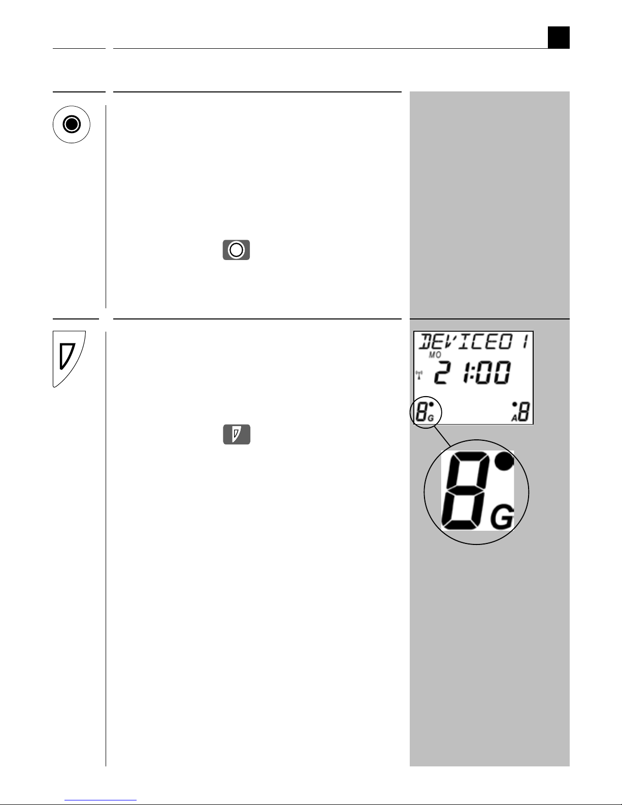
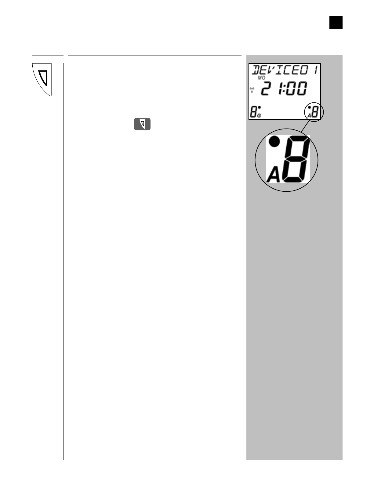
Name: Group key
Function: Select a group.
NOTE: No other group can be selected if a
point appears next to the number.
Symbol: =
13
DisplayDescriptionKeys
EN
i
Name: Member key
Function: Select a member from a group.
NOTE: No other member can be selected if a
point appears next to the number.
Symbol: =
NOTE: The following table describes the
relationship between the groups and
members view as well as the resulting
functions.
The control keys

14
EN
i
The various menu views
The respective settings are undertaken in the menus and sub-menus of the DuoFern
central operating unit. The menus are grouped according to topics, in order to provide
a clearer overview and easier configuration (e.g. manual mode / timer functions /
automatic functions / system settings).
NOTE
A complete overview of the menus can be found on page 64.
Various menu views are used depending on the application (normal mode / main
menu settings or system settings). The following pages serve to briefly describe
the menu views and the individual display icons.
15
DisplayDescriptionKeys
EN
i
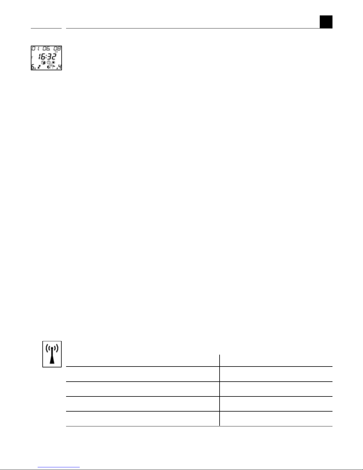
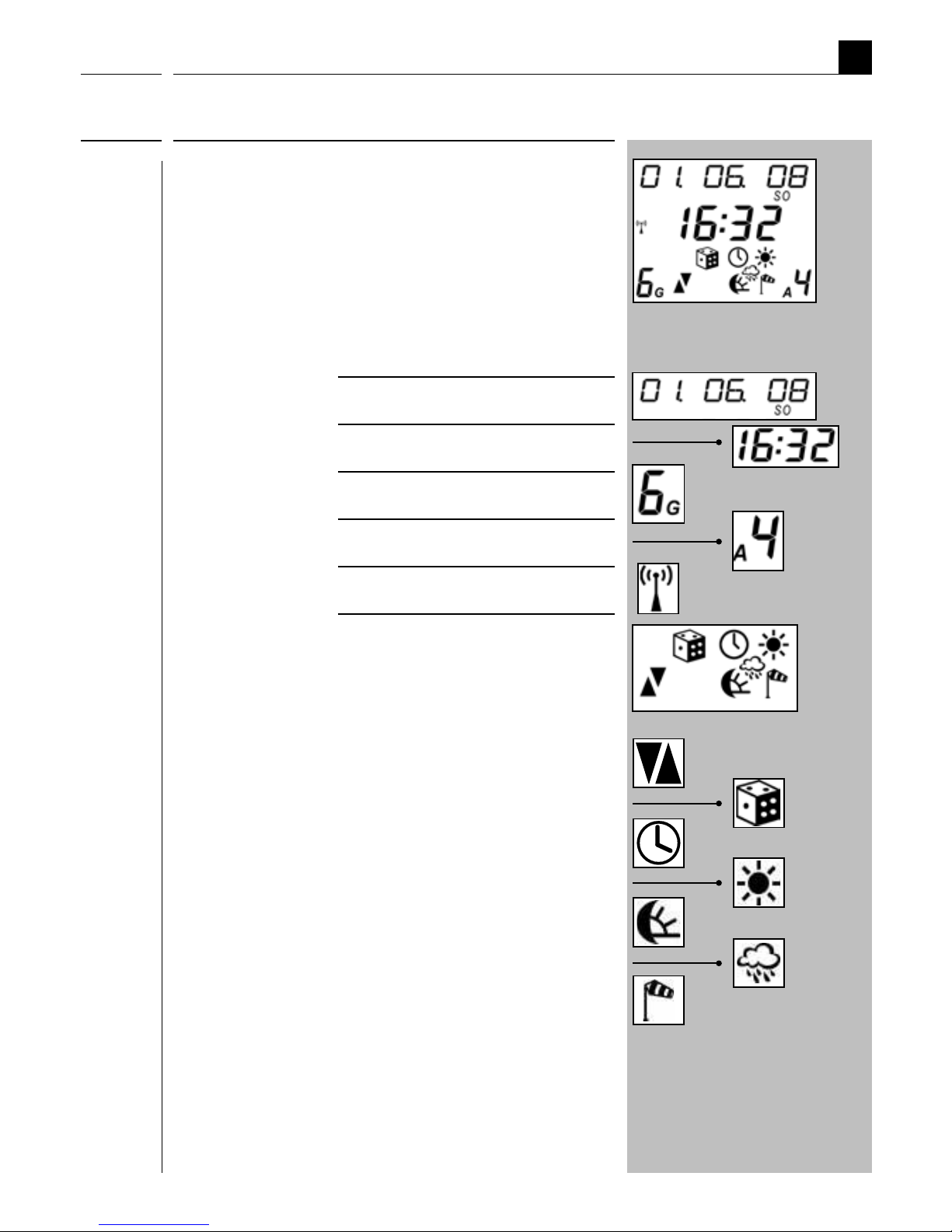
Name: Normal view
Function: Provides information on:
- The current date
- The current time
- The active group
- The active actuator
- DCF signal
- The last received status for
the selected group or
selected actuator:
Automatic switching times
Random function
Automatic timer
Automatic solar function
Automatic darkness function
Rain function
Automatic wind function
NOTE: The actuator status icons switch
off after approx. 30 seconds in order
to save the battery. Briefly pressing
the OK key causes the status to be
shown again.
Example
Normal view
16
DisplayDescriptionKeys
EN
i
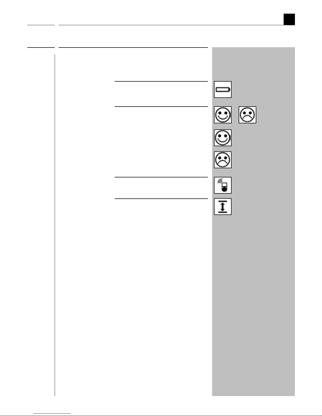
Normal view
Additional display icons in normal view:
- Battery status
- Data transfer status
Successful
data transfer
Unsuccessful
data transfer
- Radio transmission
- USB status, the central
operating unit is connected
to a computer via USB cable.
/
17
EN
i
The main menu
From the main menu you can select four sub-menus.
Graphical icons are used for these sub-menus to enable easier orientation. As soon
as a sub-menu is selected, the border flashes and the name of the menu is shown at
the top of the display in the ticker.
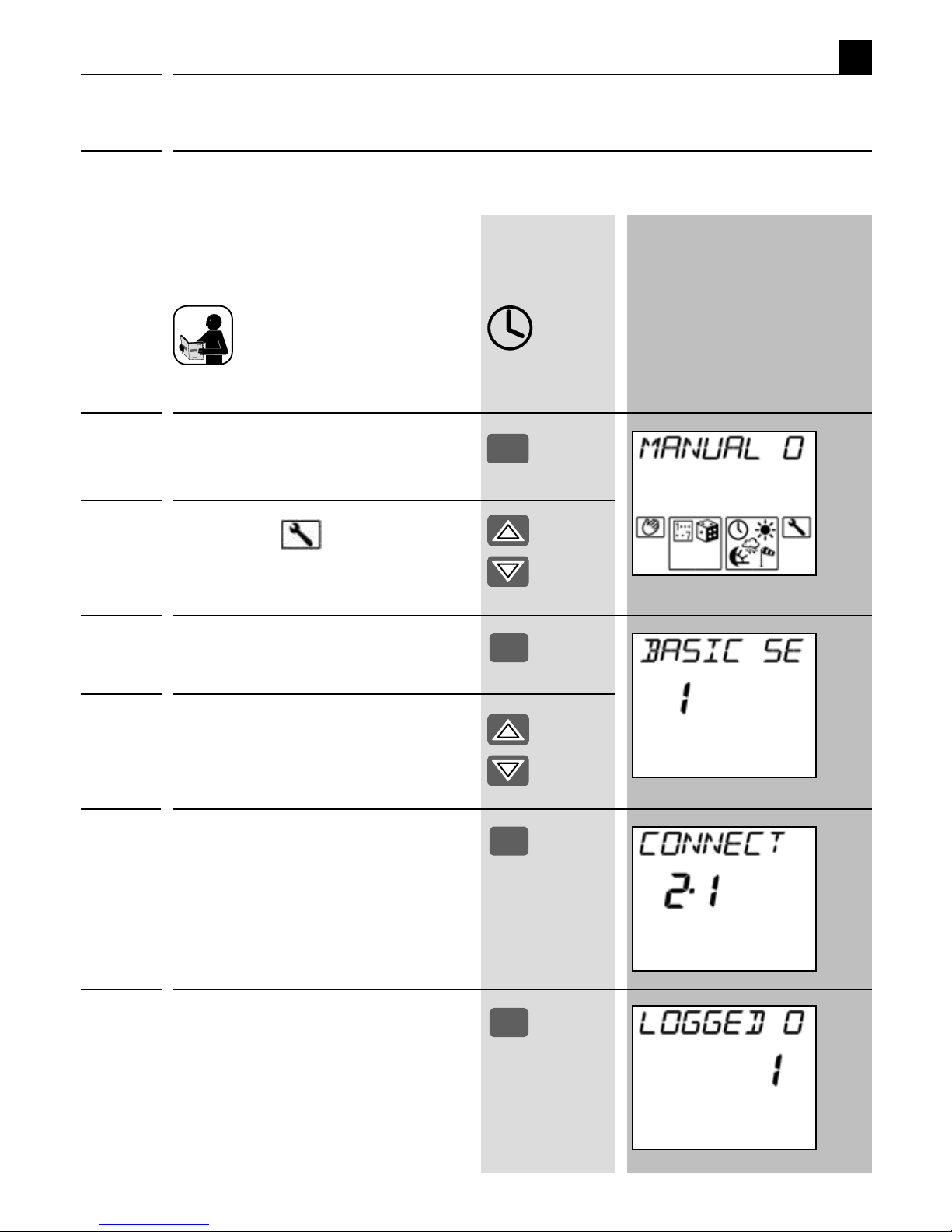
DisplayDescription
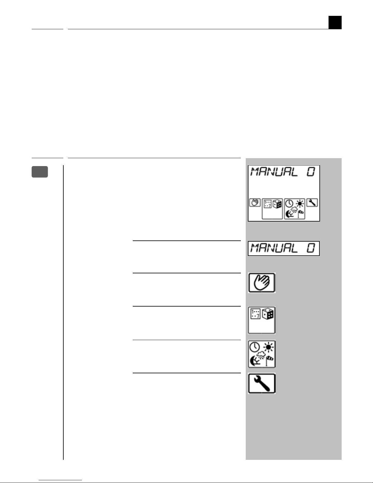
Name: Main menu
Function: Display and select menus.
Key: - Menu title (as ticker)
- Manual mode
- Timer functions
- Automatic functions
- System settings
Key
M
18
EN
i
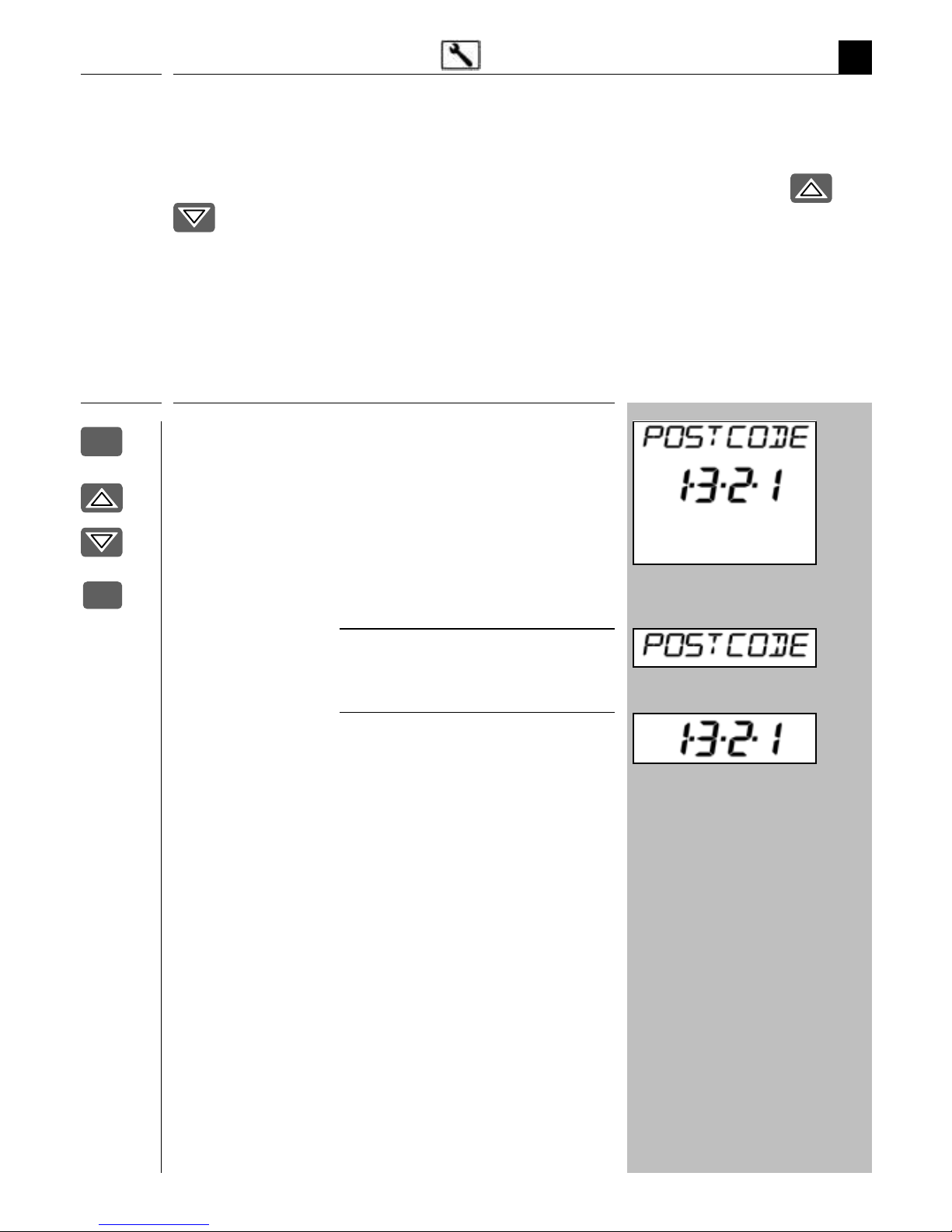
The system settings menu
DisplayDescription
Name: System settings
Function: Basic settings and individual
functions.
Key: - Menu title
- Menu number of the submenu
(e.g.
1.3.2.1 = postcode =
set postcode)
Beispiel
Keys
The "system settings" menu enables you to undertake all important basic settings
(see page 43). All of the sub-menus within the system settings menu are designated
with a menu number in order to simplify orientation. The function keys
and
enable you to quickly select the desired sub-menu and function.
NOTE
An overview of the system settings menu is provided on page 65.
M
OK

19
EN
i
Examples of application
The easiest way to familiarise yourself with the menu structure and operation of the
central operating unit is to carry out the most important tasks for setting up a DuoFern
radio network step-by-step.
In order to do so, the following pages describe several basic examples:
◆ Connecting a DuoFern actuator.
◆ Connecting a DuoFern actuator via a radio code.
◆ Configuring a switching time for a group.
◆ Setting the position of the sun for an end unit (e.g. a tubular motor via tubular
motor actuator).

20
EN
i
Examples of application
Connecting a DuoFern actuator.
Each DuoFern device (actuator/sensor) has to be assigned to the central operating
unit in order that your settings and manual switching commands can be executed.
In doing so, you can combine the DuoFern actuators into groups.
The maximum number of groups and members can be taken from the table on page 6.
Name assignment when connecting.
An individual name can be assigned to each end unit and group (e.g. lounge, etc.). A
table with the default suggested names is included on page 63.
Foregoing considerations
In order to maintain a clear overview of the settings, we suggest that you enter the end
unit assignment and desired settings into a table (name / group / member number). A
suitable template is available on our website under www.rademacher.de/download.
2.,1
21
Keys Display
EN
i
Examples of application
Connecting a DuoFern actuator.
1. Activate the actuator's connect
mode.
Connect mode remains active
for approx. 1 minute.
Approx. 1 min.
2.,1
M
OK
2. Call up the main menu.
3. Select the "
system
settings menu".
4. Confirm selection.
5. Select the menu "2 radiosettings".
6. Confirm selection.
7. Activate function "2
.
,1
Connect".
The number of connected actuators
is indicated on the display (e.g. [0]
in the event of initial installation).
OK
OK

22
Keys Display
EN
i
8. The following describes how to
connect a new actuator to the
central operating unit.
Examples of application Connecting a DuoFern actuator.
2.,1
9.a After the connection, select the
following for the new actuator:
a) a group number
b) a member number
NOTE
◆ Each channel is assigned its own
member number for multi-channel
actuators, see point 11.
◆ The central operating unit
always suggests the next free
member number automatically.
or
◆ Alternatively assign no member
number to a channel.
OK
9.b Confirm the members and
groups.
10. Subsequently assign a name for
the new actuator and the new
end unit.
M

23
Keys Display
EN
i
Connecting a DuoFern actuator.
2.,1
Examples of application
OK
11. Confirm the name of the new
end unit.
The following displays can appear:
a) Repeat points 9 to 11 for multi-
channel actuators until all of the
actuator channels are assigned.*
b) For single-channel actuators *
* Continue at 13.
12. Confirm the previously
assigned name.
The number of connected actuators
is once again indicated on the display.
13. Back to normal view.
Press the key repeatedly.
a)
b)
OK
Example
M

24
EN
i
Examples of application
Connecting a DuoFern actuator via a radio code.
2.2
The radio code can be used to directly control DuoFern actuators and connect them to
the central operating unit. Once the connection has been successfully established, you
can carry out actions such as setting the limit stops for a tubular motor.
This offers a huge advantage for operating and configuring flush-mounted devices,
as it is not necessary to dismantle them.
◆ The radio code is located on the bottom of the respective DuoFern actuator and
on a label attached to the packaging.
◆ For DuoFern radio tubular motors you will find the radio code on the motor and
on a label fitted to the connecting cable.
duofern code
43 00 A1
◆ Example of a radio code label
on the back of a DuoFern actuator.
NOTE
After switching on the power supply, the radio code for the actuator is active for
approximately 2 hours.

25
Keys Display
EN
i
Examples of application
Connecting a DuoFern actuator via a radio code.
2.2
1. Select:
M
Main menu
System settings
2 Radio settings
2.2 Radio code
2. Confirm selection.
3. Enter the six-character radio code
of the actuator and confirm each
digit.
4. If necessary you can jump back to
the previous figure to correct it.
5. Upon confirmation of the last
figure you can activate ...
M
OK
OK
M
OK
OK
6. ...the actuator's connect mode.
7. Connect the actuator to the
central operating unit. Continue
at point 2. on page 21.
OK

26
EN
i
Examples of application
Keys Display
Configuring switching times for a group
You can set individual switching times for each group in order to customise the device
to your daily requirements.
This example shows you how to configure the switching times for a group to "ALL
DAYS SAME, Mo - Su". This setting causes all of the members of the selected group to
react at the same configured switching time every day
1. Select:
M
Main menu
Time functions
Switching times
2. Confirm selection.
3.a Select the desired group.
M
OK
OK
3.b Select the desired setting, e.g.
"ALL DAYS SAME".
Options:
1 All days same *
2 Weekly program *
3 Every day different *
* A description of the
settings can be found
starting on page 33.

27
Keys Display
EN
i
OK
OK
Setting order:
◆ Hours
◆ Minutes
Optional:
◆ Hours = OFF
4. Confirm setting mode.
5. Set the desired switching time
"UP (▲)".
Confirm each entry.
NOTE
You can also deactivate each swit ching time UP (▲) / DOWN(▼) if
necessary by setting the hours to
OFF.
OK
M
6. Set the desired switching time
"DOWN (▼)".
Confirm each entry.
7. Back to the normal view
Examples of application
Configuring switching times for a group
Setting order:
◆ Hours
◆ Minutes
Optional:
◆ Hours = OFF

28
EN
i
Examples of application
Setting the position of the sun
1.1.2.1
NOTE
The end points and running time of the roller shutters must be set prior to configuration of the position of the sun(see page 48/46).
For end units with automatic solar function, the roller shutters will move to the position of the sun as soon as the solar function is activated.
Please additionally read the operating instructions for the corresponding DuoFern
actuator.
Keys Display
1. Select:
M
Main menu
System settings
1 Basic settings
1.1 Actuators
1.1.2 Special functions
1.1.2.1 Position of the sun
2. Confirm selection.
3. Select the desired member
(end unit).
M
OK
OK
/

29
Keys Display
EN
i
Examples of application
Setting the position of the sun
1.1.2.1
4. Move to the required sun
position.
The connected tubular motor moves
in the corresponding direction.
5. The tubular motor stops as soon as
the roller shutters have reached
the desired position.
NOTE
The position of the sun is displayed
as a percentage of the roller shutter's
overall travel.
6. Confirm position of the sun.
The position of the sun is stored on
the selected member or end unit.
7. Back to normal view.
M
OK
NOTE
Ensure that the automatic solar function
is activated for the actuator (see page
37).

30
EN
i
Automatic functions in the main menu
The following section serves to briefly describe the various automatic functions in
the main menu as well as their setting parameters. A corresponding menu overview
of all automatic functions is included on page 64.
It is only possible to carry out these settings if the central operating unit and the
corresponding DuoFern actuators are connected to each other and a radio connection
has been established between the devices.
NOTE
If the selected DuoFern actuator is
not detected, then dashes appear
in the display.
You can query the status of the desired
actuator again by pressing the button.
Keys Display

31
EN
Main menu
Menu overview / main menu
M
M
M
Main menu Page
Manual mode ..........................................................32
Switching times ..........................................................33
◆ PROGRAM OFF ....................................................34
1 ALL DAYS SAME .................................................34
2 WEEKLY PROGRAM.............................................34
3 EVERY DAY DIFFERENT .......................................34
Time 2 Set a secondary switching time ........................... 35
Random function ..........................................................36
Automatic timer ..........................................................36
Automatic solar function .................................................37
Automatic darkness function ...........................................38
1 MORNINGS (dawn function for mornings) ...........39
2 EVENINGS ........... (twilight function for evenings)
39
◆ CUSTOMISE........................................................39
◆ EARLIEST 40
◆ LATEST 40
◆ ON DAYS 40
Automatic rain function ..................................................42
Automatic wind function ................................................42
System settings ..........................................................43

32
DisplayDescriptionMenu
EN
Main menu
Name: Manual operation
Select:
M
Main menu
Manual mode
Setting:
On = switch on
OFF = switch off
Function: Toggles between automatic and
manual mode. Safety functions such as
"wind" are not influenced by manual
mode.
Automatic operation
Manuellbetrieb
NOTE: You can also toggle between automatic
and manual modes in the normal view.
1.
/
Select the desired device.
2.
OK
approx. 2 sec.
Press and hold the key until the
smiley icon is displayed.
IMPORTANT: Manual mode quits automatically as
soon as an automatic mode is activated
(e.g. automatic timer).
Further
important
information:
M

33
DisplayDescriptionMenu
EN
Main menu
Name: Switching times
Select:
M
Main menu
Time functions
Switching times
Setting: ◆ PROGRAM OFF
1 ALL DAYS SAME
2 WEEKLY PROGRAM
3 EVERY DAY DIFFERENT
Function: ◆ Automation of roller shutters and
additional switch actuators:
– Opening and closing times for
roller shutters.
– On and off times for additional
end units.
– Set individual switching times
per group.
◆ Configure a second switching time
per group.
– Please refer to the information on
page 51 to configure a second
switching time per group.
◆ Individual switching times can
be deactivated if:
– Hours set to OFF.
M

34
DisplayDescriptionMenu
EN
M
Name: PROGRAM OFF
All switching times are deactivated.
No additional settings can be
undertaken for the following
functions.
Name: 3 EVERY DAY DIFFERENT
Setting: 7 x UP/DOWN
Individual switching times for every
day of the week.
Name: 2 WEEKLY PROGRAM
Setting: 2 x UP/DOWN
Same switching times:
◆ from Monday to Friday
◆ for Saturday and Sunday
Name:
1 ALL DAYS SAME
Setting: 1 x UP/DOWN
The same switching times for every
day of the week from Monday to
Sunday.
NOTE:
Individual switching times can be deactivated by setting
"Hours" to "OFF"
Main menu

35
DisplayDescriptionMenu
EN
M
Configure a second switching time.
NOTE
If the "2nd switching time [
1.2.3 ]" function is activated
(see page 51), it is possible to configure a second
switching time for all previously described switching times.
The respective switching time (Time 1/ Time 2) is shown
as a ticker and left-hand digit.
Call up the first or second switching time (Time 1/
Time 2) and automatic timer.
1. Open the switching times menu. *
2.
/
1st or 2nd Select switching times.
3.
OK
Confirm selection.
4. Select desired automatic timer
(
1/2 or 3). *
5. Setting the switching times.
* see page 33
1. Switching time
"
1 ALL DAYS SAME"
2. Switching time
"
3 EVERY DAY
DIFFERENT"
Main menu

36
DescriptionMenu
EN
Display
M
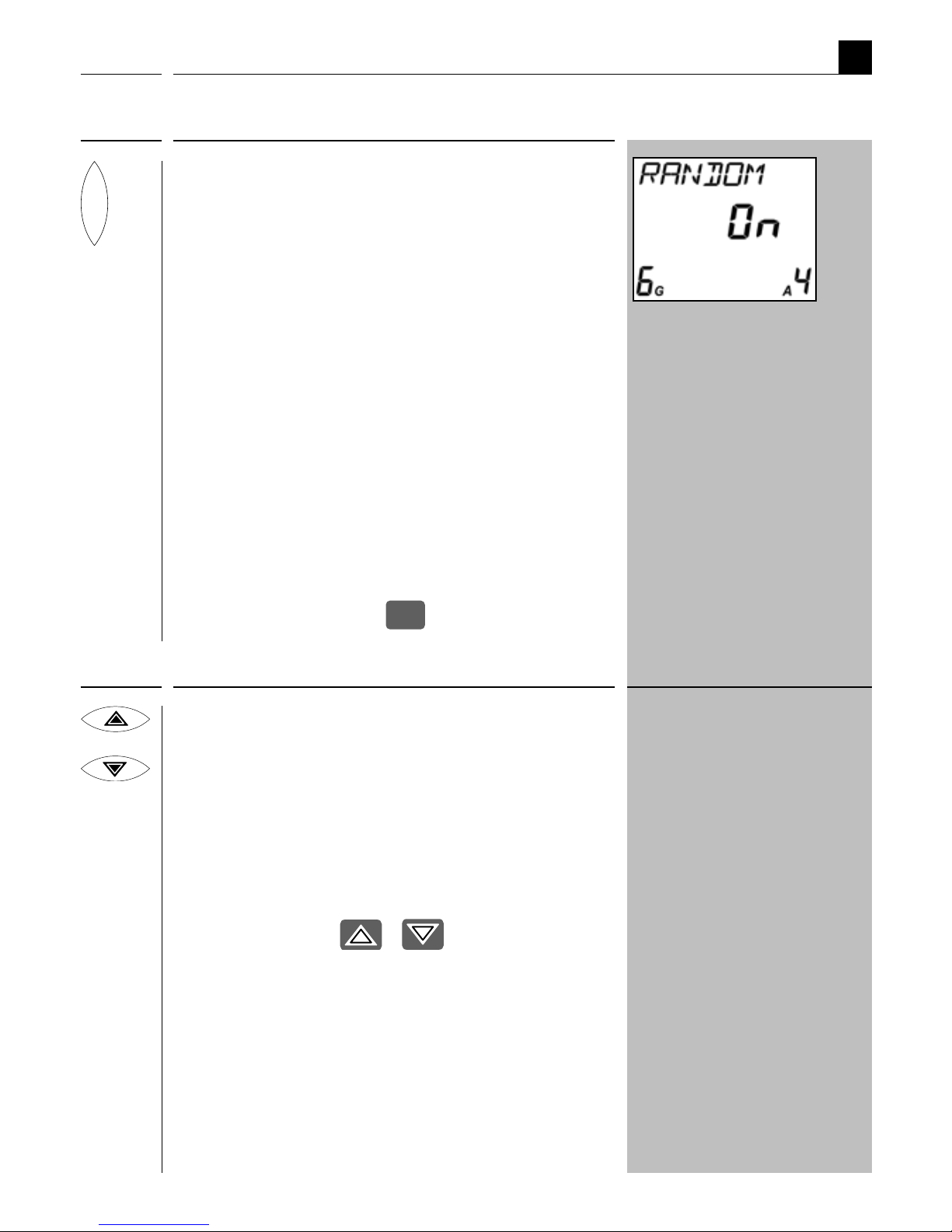
Name: Random function
Select:
M
Main menu
Time functions
Random
Function: This function causes a random delay
to the configured switching time between
0 and 30 minutes for the selected
actuator.
Further
important
information:
Name: Automatic timer
Select:
M
Main menu
Automatic functions
Time
Function: Switch the automatic timer for the
selected actuator on / off.
Further
important
information:
DisplayDescriptionMenu
Main menu

37
DisplayDescriptionMenu
EN
M
Name: Automatic solar function
Select:
M
Main menu
Automatic functions
Sun
Function: Switch the automatic solar function
for the selected actuator on / off.
NOTE
You can only activate the automatic
solar function if the position of the sun
has previously been configured for the
actuator.
Please also observe the application
example beginning on page 28.
Main menu

38
DisplayDescriptionMenu
EN
M
Main menu
Name: Dawn / Dusk
HINWEIS Astro function:
The time of the switching command
depends on the date and the geographical
location of your installation.
The settings in menu "
1.3.2 ASTRO"
must be checked (see page 54) in order
to ensure that the Astro function operates
correctly.
Select:
M
Main menu
Automatic functions
Twilight
Setting:
1 MORNINGS
2 EVENINGS
◆ AUTOMATIC
◆ CUSTOMISE
◆ EARLIEST / LATEST
◆ ON DAYS
◆ EXECUTE
Function: Selects whether the settings are to be
executed at dawn and / or dusk.

39
DisplayDescriptionMenu
EN
M
Configure the desired function.
Name: ◆ AUTOMATIC
Function: Switch the automatic darkness function
on/off for the actuator.
IMPORTANT
The following applies to actuators which
are connected in numerous groups:
You can only assign one switching
command for dawn and dusk per
actuator.
Further
important
information:
...earlier or later
- 10 10
- 20 20
- 30 30
- 40 40
- 50 50
- 60 60
Name: ◆ CUSTOMISE
Function: Change the switching time for the
automatic darkness function by +/- 60
minutes (increment = 10 minutes).
The Astro function of the central
operating unit reacts for the
selected actuator (xx) minutes...
Main menu

40
DisplayDescriptionMenu
EN
Main menu
M
Name: ◆ EARLIEST / LATEST
Function: ◆ EARLIEST
– Dawn is not executed before this
time.
◆ LATEST
– Dusk is executed at this time, at
the latest.
Name: ◆ ON DAYS
Setting:
1 MON - SUN
2 MON - SUN
3 SAT SUN
4 MON TUES WED THUR FRI SAT
SUN
Function: Dusk/dawn is executed on the selected
days:
1 MON - SUN
Every day of the week
2 MON - SUN
Monday to Friday.
3 SAT SUN
Saturday and Sunday.
4 MON TUES WED THUR FRI SAT
SUN Arbitrary selection of days.
4 Only configurable with
"WR-ConfigTool".

41
DisplayDescriptionMenu
EN
Main menu
M
Name: ◆ EXECUTE
Function: Once the automatic darkness function
has been configured, the switching
times for the dawn / dusk automatic
darkness function are shown for the
current day.

42
DescriptionMenu
EN
Display
M
Name: Rain function
Select:
M
Main menu
Automatic functions
Rain
Function: Switch the rain function for the selected
actuator on / off.
Further
important
information:
DisplayDescriptionMenu
Name: Automatic wind function
Select:
M
Main menu
Automatic functions
Wind
Function: Switch the automatic wind function
for the selected actuator on/off.
Further
important
information:
NOTE:
If the automatic wind function
has been activated, it remains
active even in manual mode.
Main menu

43
EN
System settings
The following section serves to briefly describe the various system settings and
their parameters. A brief menu overview of the menus is included on page 64.
The structure of the sub-menus is presented to you in the corresponding chapter,
for example, page 44.
Please check to see whether your actuator supports the desired function.
NOTE
The previous chapters explained in detail how to navigate through the individual
menus. For example, accessing and configuring the function "Position of the sun":
Select:
M
Main menu
System settings
1 Basic settings
1. 1 Actuators
1.1.2 Special functions
1. 1.2.1 Position of the sun
You can select and call all menus and functions in the system setting according to
this schematic.

44
EN
System settings
Menu overview / 1
.
1 Actuators
1
* All of the settings undertaken here are stored directly in the selected
DuoFern actuators and influence all actions of the DuoFern transmitters.
The actuator must be connected to the DuoFern central operating unit
and must be in the immediate vicinity in order to set the respective
option.
In doing so, observe the information provided in the operating
manual for the respective actuator.
Basic settings Page
Actuators ..........................................................44
1. 1.1 Name ..........................................................45
1.1.2 Special functions *
1.1.2.1 Position of the sun ..............................45
1.1.2.2 Ventilation / intermediate position ......45
1.1.2.3 Remote log-on / log-off
1.1.2.4 Stairway / impulse function ................. 46
1.1.2.5 Running time ......................................46
1.1.2.6 Direction of rotation / change function . 47
1.1.2.7 Wind direction of travel .......................47
1.1.2.8 Rain direction of travel ........................47
1.1.2.9 Venetian blinds function ......................47
1.1.2.A End points ..........................................48
1.1.2
.
b Software version .................................48
Groups (
1.2.1 - 1.2.4) ..................................................... 49
Central operating unit (
1.3.1 - 1.3.7) ...............................52
Sensors (
1.4.1 - 1.4
.
d) ....................................................57
1.1
1.2
1.3
1.4

45
EN
DescriptionMenu
Menu overview / 1
.
1 Actuators
Description
Name: Name
Function: Enter a name for the current actuator. A table with the default
suggested names is included on page 63.
NOTE
You can customise the names using the WR ConfigTool software.
Menu
1. 1.1
Name: Sun position
Function: Setting the position of the sun for the current actuator.
For key function and order, see page 28.
1. 1.2.1
Name: Ventilation / intermediate position
Function: ◆ Switch the ventilation position on / off.
◆ Set the ventilation position.
The ventilation position setting corresponds to the settings for
the position of the sun from point 2 on page 28. Repeat these
settings for the ventilation position.
1. 1.2.2
DescriptionMenu

46
EN
DescriptionMenu
Menu overview / 1
.
1 Actuators
Name: Stairway / impulse function
Function: Switch the stairway / impulse function on / off for the selected actuator.
Additional configuration options are available with the
"WR ConfigTool" software.
If the stairway counter is set very low, then the actuator will generate
a corresponding impulse.
1. 1.2.4
DescriptionMenu
Name: Running time
Function: Configures the running time for opening a roller shutter.
If the roller shutter drive is configured to move to specific positions
(e.g. position of the sun / ventilation position), then the running
time for opening and closing the roller shutter should be determined
and entered in advance.
Proceed as follows:
1. Measure the opening time of the roller shutter.
2. Select the actuator which is connected to the roller shutter drive.
3. Enter the measured opening time plus 2 seconds.
1. 1.2.5
DescriptionMenu
Name: Remote log on / off
Function: Activate connect / disconnect mode for an actuator.
Subsequently, you can connect a DuoFern flush-mounted actuator
with another DuoFern manual transmitter, for example.
Connect
Quit connect / disconnect mode
Disconnect
1
. 1.2.
3

47
EN
Menu overview / 1
.
1 Actuators
Name: Change direction of rotation / function
Function: Reverse the direction of rotation for an actuator to control roller
shutters
or
Change the function of an actuator.
1. 1.2.6
DescriptionMenu
Name: Wind direction of travel
Function: Set the direction of travel for an actuator in the event that "wind" is
detected for an active automatic wind function.
1. 1.2.7
DescriptionMenu
Name: Rain direction of travel
Function: Set the direction of travel for an actuator in the event that "rain"
is detected for an active automatic wind function.
1. 1.2.8
DescriptionMenu
Name: Venetian blinds function
Function: Switch the Venetian blinds function on/off for the selected
actuator.
Additional configuration options are available with the
"WR ConfigTool" software.
1. 1.2.9
DescriptionMenu

48
EN
Menu overview / 1
.
1 Actuators
Name: End points
Function: Set the upper and lower end point for the currently selected drive.
Proceed as follows:
1.
/ Move the roller shutters to the centre position.
2. Call up the menu "
1.1.2.A".
3.
/ Press and hold the required key; the roller
shutter moves up or down..
4. Release the button as soon as the desired end point is reached.
IMPORTANT
Release the key promptly and never allow it to extend beyond
the respective limit stop. Failure to do so can cause overloading
and may damage the drive.
5. The roller shutter stops and the upper / lower end point is stored.
Adjusting the end points:
6. Repeat the above steps.
1. 1.2.A
DescriptionMenu
Description
Menu
Name: Software version
Function: Displays the software version for the currently selected actuator.
1. 1.2
.
b

49
EN
Menu overview / 1
.
2 Groups
Basic settings Page
Actuators (
1.1.1 - 1.1.2).....................................................44
Groups (
1.2.1 - 1.2.4) ..................................................... 49
1.2.1 Name ..........................................................50
1.2.2 Member ..........................................................50
1.2.3 2nd switching time ............................................51
1.2.4 Venetian blinds function / jog mode ...................51
Central operating unit (
1.3.1 - 1.3.7) ...............................52
Sensors (
1.4.1 - 1.4
.
d) ....................................................57
1
1.1
1.2
1.3
1.4
System settings

50
EN
Menu overview / 1
.
2 Groups
DescriptionMenu
Name: Name
Function: Select a name for the current group.
A table with the default suggested names is included on page 63.
Additional configuration options are available with the
"WR ConfigTool" software.
1.2.1
DescriptionMenu
Name: Members
Function: Assign a connected DuoFern actuator as a member of a group.
NOTE
◆ The actuator may not already be a member of this group.
◆ If the desired member number is already assigned, then the
original member will be removed from the group.
Proceed as follows:
1. Select the desired group and the member number for
the new actuator.
2. Select the actuator that you wish to assign.
How to remove a member from a group:
1. Select group and member.
2. Select "FREE".
NOTE
The actuator has now been removed from the group, but is still
connected to the central operating unit.
1.2.2

51
EN
DescriptionMenu
Name: 2nd switching time
Function: Switch the second switching time for a group on / off. Instructions
on how to configure a second switching time are given on page 35.
1.2.3
Menu overview / 1
.
2 Groups
DescriptionMenu
Name: Venetian blinds function / jog mode
Function: If jog mode is active, a corresponding movement command is transmitted
in normal mode by briefly pressing "
or ". The drive moves
gradually in the desired direction.
Travel command with jog mode deactivated.
If one of the two keys is held down with jog mode deactivated, then
the command "up" or "down" is transmitted.
Jog mode for dimming or adjusting the position
of Venetian blinds.
Switch on jog mode for the group if you want to gradually adjust a
dimmer in steps or the slat position for Venetian blinds.
1.2.4

52
EN
Menu overview / 1
.
3 Central operating unit
1
Basic settings Page
Actuators (
1.1.1 - 1.1.2).....................................................44
Groups (
1.2.1 - 1.2.4) ..................................................... 49
Central operating unit (
1.3.1 - 1.3.7) ...............................52
1.3.1 Time
1.3.1.1 Settings .............................................. 53
1.3.1.2 DCF clock ............................................53
1.3.1.3 DCF quality .........................................53
1.3.1.4 SU-WI time .........................................54
1.3.2 Astro
1.3.2.1 Postcode ............................................. 54
1.3.2.2 Astro times .........................................55
1.3.2.3 Twilight ..............................................55
1.3.3 Key lock ..........................................................55
1.3.4 Contrast ..........................................................56
1.3.5 Ticker ..........................................................56
1.3.6 Language ..........................................................56
1.3.7 Version ..........................................................56
Sensors (
1.4.1 - 1.4
.
d) ....................................................57
1.1
1.2
1.3
1.4
System settings

53
EN
DescriptionMenu
Name: Settings (time)
Function: Manual settings for time and date. The setting is undertaken automatically
one after the other.
NOTE
This function is only accessible if:
◆ No DCF signal has been received.
◆ DCF reception is deactivated.
◆ Directly after inserting the batteries.
1.3.1.1
DescriptionMenu
Name: DCF clock
Function: Switch DCF signal reception on/off.
NOTE
Additional information about the DCF radio timer is given on page 9.
1.3.1.2
Menu overview / 1
.
3 Central operating unit
DescriptionMenu
Name: DCF quality
Function: Checks the quality of the received DCF signal.
0 No DCF reception
5 good DCF reception
1.3.1.3

54
EN
Menu overview / 1
.
3 Central operating unit
DescriptionMenu
Name: SU-WI time
Function: Switches automatic daylight saving time switch-over on / off.
Proceed as follows to activate automatic switch-over:
1. Activate Su-Wi switch-over.
2. Set the desired broadcasting time.
NOTE
If you set a broadcasting time prior to the actual switch-over, the
new time will be broadcast immediately once the switch-over is
reached.
1.3.1.4
DescriptionMenu
Name: Postcode
Function: Enables input of your postcode.
The postcode is required for execution of the Astro function. Once
the postcode has been entered, the program can calculate the switching
times for automatic darkness function.
0 - 99 German postcodes
This enables you to enter the first two digits of
your postcode.
100 - 255 code for various European cities
(see table on page 61).
1.3.2.1

55
EN
DescriptionMenu
Name: Astro times
Function: Enables you to view the calculated twilight times for the
selected postcode.
1.3.2.2
DescriptionMenu
Name: Twilight
Function: Switches the twilight time calculation function on / off on the
central operating unit.
1.3.2.3
Menu overview / 1
.
3 Central operating unit
Name: Key lock
Function: Activate / deactivate key lock or menu lock.
This enables you to prevent unintentional operation of the central
operating unit.
OFF no key lock
1 The main menu cannot be accessed from the normal view.
2 All key presses are ignored.
NOTE
The selected lock is activated in normal view if no key input
is made within 2 minutes.
M
+
OK
This temporarily deactivates the
key lock.
1.3.3
DescriptionMenu

56
EN
Menu overview / 1
.
3 Central operating unit
DescriptionMenu
Name: Contrast
Function: Enables the display contract to be set.
1 low contrast
5 high contrast
1.3.4
DescriptionMenu
Name: Ticker
Function: Setting the ticker speed.
1 slow
8 fast
1.3.5
DescriptionMenu
Name: Language
Function: Set the desired language.
1 German
2 English
3 Spanish
4 French
5 Dutch
1.3.6
DescriptionMenu
Name: Version
Function: Displays the current version number for the software on the central
operating unit.
1.3.7

57
EN
Menu overview / 1
.
4 Sensors
1
DuoFern sensors offer an interface to our environment.
If you have selected a function from the menu "
1.4 Sensors" and none of the
sensors connected to the central operating unit support this function, the
message "Not Possible" appears in the display. This message also appears
if you have still not connected any sensor to the central operating unit.
Please refer to the operating manual for the respective DuoFern
sensor for information about how to configure and operate your
sensor with the DuoFern central operating unit.
System settings
Basic settings Page
Actuators (
1. 1.1 - 1.1.2) ................................................... 44
Groups (
1.2.1 - 1.2.4) ..................................................... 49
Central operating unit (
1.3.1 - 1.3.7) ...............................52
Sensors (
1.4.1 - 1.4
.
d) ....................................................57
1.4.1 Sun
1.4.2 Position
1.4.3 Twilight
1.4.4 Wind
1.4.5 Rain
1.4.6 Temperature
1.4.7 DCF clock
1.4.8 Time
1.4.9 Astro
1
.4.
A Remote log-on / log-off
1.4
.
b Test
1.4.C Clear
1.4
.
d Software Version
1.1
1.2
1.3
1.4

58
EN
Menu overview / 2 Radio settings
System settings
2
DescriptionMenu
Name: Connect / disconnect
Function: Connect a DuoFern actuator to the central operating unit or disconnect
from the central operating unit.
Start connect mode on the central operating unit
Quit connect / disconnect mode on the
central operating unit
Start disconnect mode on the central operating unit.
2.1
Radio settings Page
Connect/disconnect ........................................................58
Radio code ..........................................................59
Clear ..........................................................59
2.1
2.2
2.3

59
EN
DescriptionMenu
Name: Radio code
Function: Switches a DuoFern device to connect or disconnect mode with the
radio code (see application example on page 24).
Connect
Quit connect / disconnect mode
Disconnect
NOTE
For security reasons, this function is only available for the
first two hours after switching on the power supply.
Further
important
information:
2.2
Menu overview / 2 Radio settings
DescriptionMenu
Name: Clear
Function: Disconnect all DuoFern devices from the central operating unit which
are no longer accessible via radio.
Start the "Clear" function.
The central operating unit attempts to contact all of the
connected DuoFern devices. All DuoFern devices which fail
to provide a return signal are disconnected from the central
operating unit.
NOTE
a) Battery operated DuoFern devices are not checked.
b) Only start this function when in the immediate
vicinity of all connected DuoFern devices.
2.3

60
EN
TD Technical Specifications
Battery replacement
The battery icon flashes in the normal view when the battery is nearly empty. We
recommend exchanging the battery at this time. The battery compartment is located
on the back of the central programming unit.
NOTE
Ensure that the batteries are inserted in accordance with their polarity. This is
indicated on the bottom of the battery compartment. Only use the following
battery type: 3 x 1.5 V type AAA (Micro).
TD
Supply voltage: 4.5 V
Battery type: 3 x 1.5 V type AAA (micro)
Battery life: approx. 2 years
Transmission frequency: 434.5 MHz
Transmission power: 10 mW
Range: 100 m (outdoors)
Clock: DCF radio timer
DCF reception (range): approx. 1500 km from Frankfurt am
Main / Germany
Max. number of groups: 9
Max. number of members per group: 9
Number of end units: 81 (total)
Ambient conditions: Device may only be used in dry rooms.
Dimensions (W x L x H) 54 x 142 x 24 mm

61
EN
i
Time zone table
Germany
0 - 99 postcode
Belgium
100 Arlon
101 Antwerp
102 Bruges
103 Brussels
104 Liège
105 Mechelen
106 Mons
107 Ostend
Denmark
108 Aalborg
109 Ringsted
110 Esbjerg
111 Horsens
112 Kolding
113 Copenhagen
114 Svendborg
115 Randers
England
116 Aberdeen
117 Birmingham
118 Bristol
119 Glasgow
120 London
121 Manchester
122 Newcastle
Estonia
123 Tallinn
Finland
124 Helsinki
125 Jyyäskylä
126 Oulu
127 Tampere
128 Turku
129 Vasa
France
130 Bordeaux
131 Brest
132 Dijon
133 Le Havre
134 Lyon
135 Montepellier
136 Nantes
137 Nice
138 Paris
139 Reims
140 Strasbourg
141 Toulon
Italy
142 Bologna
143 Bolzano
144 Florence
145 Genoa
146 Milan
147 Naples
148 Palermo
149 Rome
150 Turin
151 Venice
Ireland
152 Cork
153 Dublin
154 Belfast
Latvia
155 Riga
Liechtenstein
156 Vaduz
Lithuania
157 Vilnius
Luxembourg
158 Luxembourg
The Netherlands
159 Amsterdam
160 Eindhoven
161 Enschede
162 Groningen
163 Maastricht
164 Rotterdam
165 Utrecht
Norway
166 Oslo
167 Stavanger
168 Bergen
169 Trondheim
Austria
170 Amstetten
171 Baden
172 Braunau
173 Brixen
174 Bruck/mur
175 Eisenstadt
176 Graz
177 Innsbruck
178 Klagenfurt
179 Landeck
180 Linz
181 Nenzing
182 Salzburg
183 Vienna

62
EN
i
Time zone table
Poland
184 Wrocław
185 Bromberg
186 Danzig
187 Kattowitz
188 Krakow
189 Lodz
190 Lublin
191 Posen
192 Stettin
193 Warsaw
Portugal
194 Faro
195 Lisbon
196 Porto
Switzerland
197 Basel
198 Bern
199 Andermatt
200 Chur
201 Lausanne
202 Lucerne
203 Zurich
Sweden
204 Boras
205 Gävle
206 Gothenburg
207 Helsingborg
208 Jönköping
209 Östersund
210 Malmö
211 Stockholm
212 Sundsvall
213 Umea
Spain
214 Almería
215 Alicante
216 Barcelona
217 Bilbao
218 Badajoz
219 Burgos
220 Cáceres
221 Castellón
222 Granada
223 Guadalajara
224 La Coruña
225 Lérida
226 León
227 Madrid
228 Murcia
229 Oviedo
230 Palma
231 Pamplona
232 San Sebastián
233 Seville
234 Santander
235 Valencia
236 Valladolid
237 Vitoria
238 Zaragoza
239 La Palma
240 Tenerife
241 Grand Canaria
242 Fuerteventura
South-East Europe
243 Athens
244 Belgrade
245 Bratislava
246 Bucharest
247 Budapest
248 Istanbul
249 Maribor
250 Prague
251 Sarajevo
252 Sofia
253 Skopje
254 Thessaloniki
255 Zagreb

63
EN
i
No. Name
1 DEVICE XX / GROUP Y
2 STORE ROOM
3 WORKROOM
4 BATHROOM
5 SURGERY
6 LIBRARY
7 IRONING ROOM
8 OFFICE
9 ATTIC
10 ROOF LIGHT
11 ENTRANCE
12 MASTER BEDROOM
13 GROUND FLOOR
14 DINING ROOM
15 FLOOR
16 LOUNGE
17 HALL
18 FOYER
19 SPARE ROOM
20 GARDEN
21 HOBBY ROOM
22 VENETIAN BLINDS
23 FIREPLACE ROOM
24 CELLER
25 NURSERY
26 KITCHEN
27 LAMP
Suggested names for groups and members
No. Name
28 FAN
29 AWNING
30 MEDIA ROOM
31 MOTOR
32 NORTH
33 UPPER FLOOR
34 EAST
35 PUMP
36 ROLLER SHUTTERS
37 BEDROOM
38 STANDARD LAMP
39 SOUTH
40 PATIO
41 TOILET
42 STAIRWAY
43 CURTAINS
44 STORE ROOM
45 ANTEROOM
46 WAITING ROOM
47 WC LADIES
48 WC GUESTS
49 WC GENTLEMEN
50 CRAFT ROOM
51 WORKSHOP
52 WEST
53 LIVING ROOM

64
EN
i
Menu overview
System settings (see next page)
1 Basic settings (1
.
1 - 1.4)
2 Radio settings (2
.
1 - 2.3)
Automatic functions
Time
Sun
Rain
Wind
Twilight
Normal view (example)
Main menu
Manual operation
Time functions
Switching times
Random

65
EN
i
1
1.1
1.2
1.3
1.4
2
2.1
2.2
2.3
Menu overview
Basic settings Page
Actuators (
1.1.1 - 1.1.2)......................................44
Groups (
1.2.1 - 1.2.4) ...................................... 49
Central operating unit (
1.3.1 - 1.3.7) ................52
Sensors (
1.4.1 - 1.4
.
d) ....................................57
Radio settings Page
Connect/disconnect ......................................... 58
Radio code ......................................................59
Clear ............................................................... 59
System settings

66
EN
i
CE Mark and EC Conformity
The present product complies with the requirements of the current European and
national directives.
1999/5/EC
R&TTE directive
Conformity has been verified. The corresponding declarations and documentation are
available on file at the manufacturer’s premises.
RADEMACHER Geräte-Elektronik GmbH & Co. KG
Buschkamp 7
46414 Rhede

67
EN
i
Warranty conditions
RADEMACHER Geräte-Elektronik GmbH & Co. KG provides a 24-month warranty for
new systems that have been installed in compliance with the installation instructions.
All construction faults, material defects and manufacturing defects are covered by
the warranty.
The following are not covered by the warranty:
◆ Incorrect fitting or installation
◆ Non-observance of the installation and operating instructions
◆ Improper operation or wear and tear
◆ External influences, such as impacts, knocks or weathering
◆ Repairs and modifications by third party, unauthorised persons
◆ Use of unsuitable accessories
◆ Damage caused by unacceptable excess voltage (e.g. stroke of lightning)
◆ Operational malfunctions caused by radio frequency overlapping and other
such radio interference
RADEMACHER shall remedy any defects, which occur within the warranty period
free of charge either by repair or by replacement of the affected parts or by supply
of a new replacement unit or one to the same value. There is no general extension
of the original warranty period by delivery of a replacement or by repair as per the
terms of the warranty.

RADEMACHER
Geräte-Elektronik GmbH & Co. KG
Buschkamp 7
46414 Rhede (Germany)
info@rademacher.de
www.rademacher.de
Service:
Hotline 01807 933-171*
Fax +49 2872 933-253
service@rademacher.de
* 30 seconds free of charge, subsequently 14 cents / minute from
German fixed line networks and max. 42 cents / minute from
German cellular networks.
Subject to technical modifications, misprints and errors. Illustrations not binding.
 Loading...