

DUO AIRE CI-108 Installation Manual
INSTALLATION MANUAL
This manual provides installation & operating instructions
BUILT IN
ACCORDANCE
WITH
NFPA 96
NOTIFY CARRIER OF DAMAGE AT ONCE.
It is the responsibility of the consignee to inspect the container upon receipt of same and to determine the
possibility of any damage, including concealed damage. Duo-Aire suggests that if you are suspicious of damage
to make a notation on the delivery receipt. It will be the responsibility of the consignee to file a claim with the
carrier. We recommend that you do so at once.
4000 Portage Road, Suite 205/206, Kalamozoo, MI 49001 Phone (616) 343-2475 Fax (616) 343-2438

Retain this manual for future reference.
Notice: Due to a continuous program of product improvement, Duo-Aire
reserves the right to make changes in design and specifications without
prior notice.
Notice: Please read the entire manual carefully before installation.
If certain recommended procedures are not followed, warranty claims
will be denied.
Model Number
Serial Number
Installation Date
Safety Procedures
• Always Disconnect power cord before attempting to work on or to clean
equipment. Turning the switch off is insufficient as the power remains live
to the cabinet and can be a hazard.
• Route the power cord so that it is not likely to be walked on or pinched by
other appliances.
• Do not overload outlets with too many appliances. This can result in fire
or electrical shock.
• Disconnect plug when the appliance will be idled for a long period of time.
• Do not attempt to service this unit yourself as removing covers may
cause unnecessary exposure to dangerous voltage.
• Never connect the unit to a power source while standing in water. Wet
hands and wet floors should be avoided when connecting any electrical
appliance to a power outlet.
• When a replacement part is required, always insist on factory authorized
parts.

Index
INSTALLATION INSTRUCTIONS
Installation Requirements for Duo-Aire Hoods ........................ ....... Page 2
Canopy Hoods ................................................................................ Page 2
Low Side Wall Ventilators................................................................ Page 3
Pizza Oven Hoods ........................................................................... Page 4
Exhaust Fans & Ducts .................................................................... Page 5
Fresh Air Supply Fans ..................................................................... Page 6
Hoods with Air Volume Controllers
- Adjustment Instructions ............................................................... Page 7
Side Skirts ...................................................................................... Page 8
Top Enclosure Panels...................................................................... Page 9
Stainless Steel Wall Panels............................................................. Page 10
OPERATING INSTRUCTIONS START - CHECK - BALANCE
Direct Draw Hoods......................................................................... Page 11
Make-Up Air Hoods......................................................................... Page 12
FINAL AIR BALANCE
Make-Up Air Hoods......................................................................... Page 12
Air Balance Report ......................................................................... Page 13
Notes and Worksheet .................................................................... Page 14
Page 1
INSTALLATION INSTRUCTIONS
Installation Requirements For All Duo-Aire Hoods
Duo-Aire hoods are provided with slotted hanging brackets designed to receive 1/2" threaded rod
with a 1/2" bolt and washer. Supporting rods must be connected to all factory installed brackets.
Recommended hanging height is 6'- 6" above finished floor for canopies. Low side wall ventilators
should be installed directly upon a Duo-Aire base or on a fire rated wall. If wall mounted, the bottom of
the vent should be 36" above finished floor.
ALL DUO-AIRE VENTILATION SYSTEMS MUST BE INSTALLED IN ACCORDANCE WITH NFPA-96,
REMOVAL OF SMOKE AND GREASE-LADEN VAPORS FROM COMMERCIAL COOKING EQUIPMENT.
CANOPIES
1. Check all local codes prior to installation. Special requirements may be necessary
depending upon building material construction.
2. Move crated hood to location of installation and very carefully uncrate hood.
3. Raise hood to proper hanging height.
4. Suspend hood from adequate roof supports using 1/2" threaded rods with nuts
and washers. (See Fig. 1)
5. Level hood left to right and front to back.
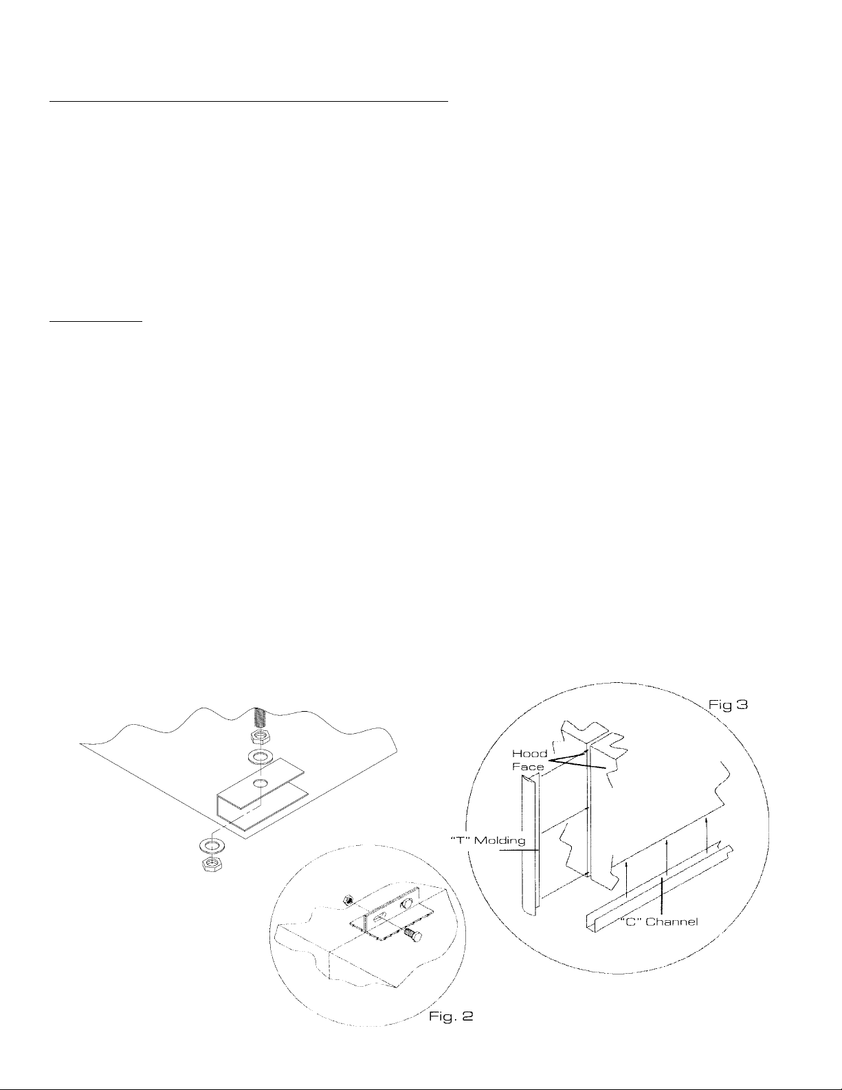
6. Brackets are provided for hoods which are to be installed end to end or back to
back. Bolt brackets together using 3/8" bolt through holes provided. (See Fig. 2)
7. Install “C” channel where the ends of hood meet and install “T” moldings on front
face of hoods where they join. High temperature silicone can be used to install “C”
and “T” moldings. (See Fig. 3)
8. For Make-up air hoods, the supply collar with built-in U.L. listed fire damper, and air volume damper must
be installed per instructions on collar.
9. Provide a removable service door in supply duct near fire damper. (See Fig. 5)
Fig.1
Page 2
LOW SIDE WALL VENTILATORS
1. Check all local codes prior to installation. Special requirements may be necessary
depending upon building material construction.
2. Move crated hood to location of installation and very carefully uncrate vent.
3. If vent is base mounted, base must be installed and leveled front to back and left to
right.
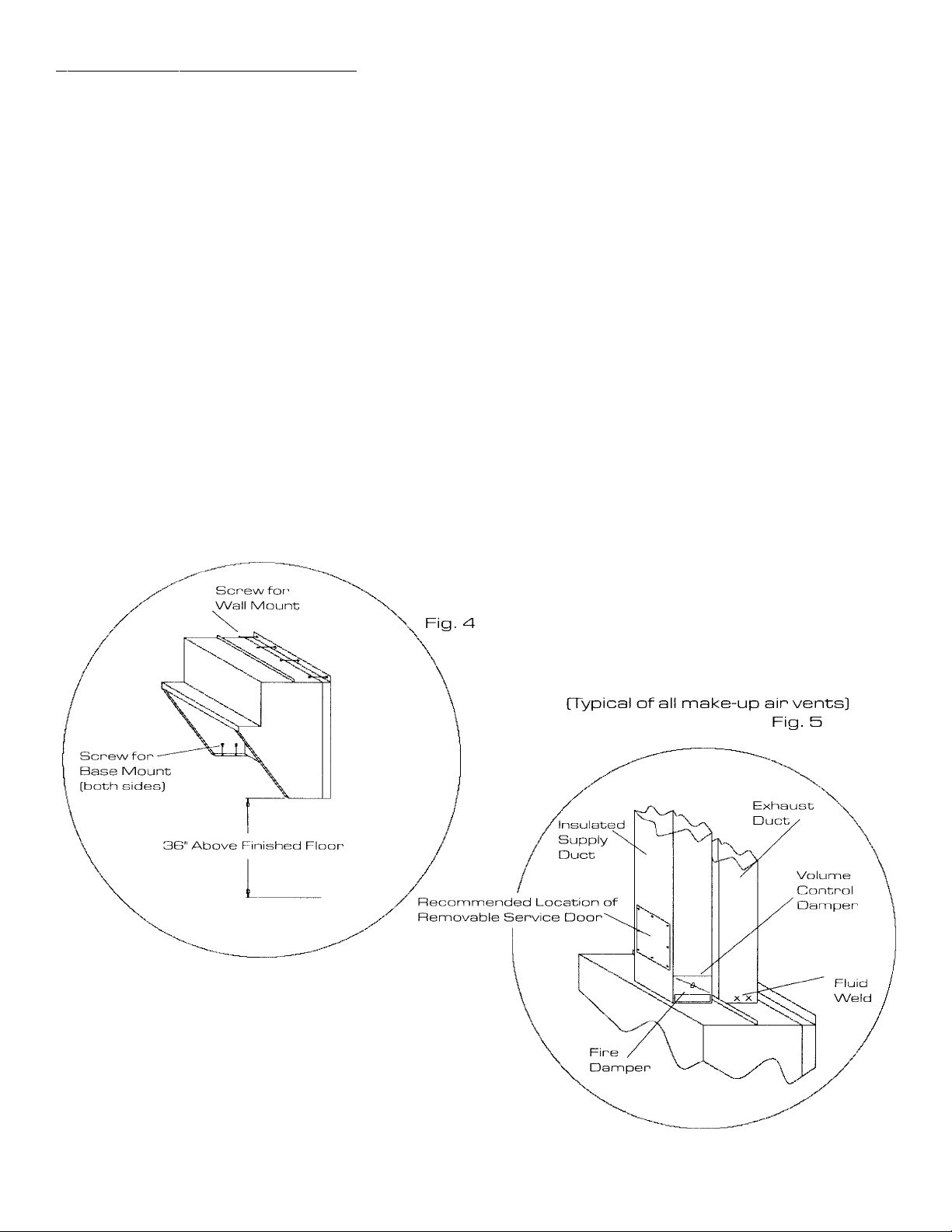
4. Place vent on base. Secure vent to base by screwing side walls of vent to base. (See Fig. 4)
5. If vent is wall mounted, place vent on wall, level front to back and left to right, then
bolt metal hanging bracket located on top of hood to wall. (See Fig. 4)
6. Bottom of ventilator should be 36" above finished floor. (See Fig. 5)
7. Fluid weld exhaust duct to hood exhaust duct collar. (See Fig. 5)
8. For Make-up air ventilators, the supply collar with built-in U.L. listed fire damper, and air
volume damper must be installed per instructions on collar.
9. Attach air supply duct work to supply collar. DO NOT SCREW INTO FIRE
DAMPER.
10. Provide a removable service door in supply duct near fire damper. (See Fig. 5)
*
* WHEN USING FLOOR FRYERS,
CONFIRM FLUE HEIGHT
Page 3
 Loading...