

Page 1
1 of 165
_________________________________________________________________________________________
DUAL FUEL BURNERS
TD/TAD4
GENERAL INFORMATION
AND
OPERATING MANUAL
Page 2

Operating Instructions For TD/TAD4 Dual Fuel Burner
June 13 2 of 165 TD/TAD4 Manual Rev 4
Revision Table
Rev No.
Description
Date
By
1
2
3
4
Emergency stop information added - section 5.9
Exploded drawings revised – section 11
6.6.13
R.S
Page 3

Operating Instructions For TD/TAD4 Dual Fuel Burner
June 13 3 of 165 TD/TAD4 Manual Rev 4
`TD/TAD` SERIES DUAL FUEL BURNERS
GENERAL INFORMATION AND OPERATING MANUAL
IMPORTANT
Throughout this publication Dunphy Combustion Limited are referred to as `The Company`.
The manual, which is supplied with every burner, should be read prior to the installation of the unit.
While giving information on the site work involved and on the burner commissioning procedure,
the content cannot include all of the data which may be necessary to achieve the design output of a
burner to a particular appliance because of the wide variety of heating and process plant for which
the burner is suitable precludes this.
The Company strongly advises that the commissioning of the burners is carried out by Dunphy
trained engineers and points out that it may be impossible to impart all the necessary information to
enable others to do so.
Under all circumstances the provisions of The Health and Safety at Work Act 1974 are the most
important consideration and if any doubts exist concerning the safe operation of the burner, The
Company should be contacted for advice. This provision also applies to the legislation of countries
to which the burners may be exported.
Where equipment, not of The Company`s supply, is used in conjunction with the burners, reference
should be made to specific instructions or regulations governing the installation and use of such
equipment.
The Company gratefully acknowledges the permission of component suppliers and others to
reproduce data sheets and technical information in this manual.
For reliable and efficient operation of the burner, it is essential that regular maintenance is carried
out in accordance with the instructions contained in the text of this manual. The fact that a burner
may be under warranty does not absolve the user from the responsibility for this and inadequate
maintenance may lead to claims, made under guarantees of materials or performance being denied
IF IN DOUBT - ASK!
Information contained in this manual is given without any responsibility on the part of the company
for the consequences of the actions of persons making use of such information.
Equipment is supplied strictly under the terms of The Company’s current `Conditions of Supply`
which are printed on the reverse of order acknowledgements and delivery notes.
Copies are available on request.
Page 4

Operating Instructions For TD/TAD4 Dual Fuel Burner
June 13 4 of 165 TD/TAD4 Manual Rev 4
Contents
1 General Information ...................................................................................................................................... 7
1.1 General ............................................................................................................................................................ 7
1.2 Working parameters ................................................................................................................................... 7
1.3 Fuels ................................................................................................................................................................. 7
1.3.1 Fuel Tanks .............................................................................................................................................. 8
1.3.2 Filtration .................................................................................................................................................. 8
1.3.3 Ring Main Pumps .................................................................................................................................. 8
1.3.4 Pipe Runs ................................................................................................................................................ 8
1.3.5 Burner Connection ............................................................................................................................... 8
1.3.6 Burner Filtration ................................................................................................................................... 8
1.3.7 Pressure Regulation ............................................................................................................................ 8
1.3.8 Oil Line Connections ........................................................................................................................... 9
1.4 Burner construction .................................................................................................................................... 9
1.5 Burner details and power curve ........................................................................................................... 12
1.6 General arrangement details ................................................................................................................. 13
1.6.1 High low/modulating burners on gas, high low on oil ......................................................... 13
1.6.2 Electronic modulation burners (M RT) ....................................................................................... 14
1.6.3 TD10-415 Multi – Fuel Low Nox Burner General Arrangement ........................................ 16
1.6.4 TD420 Multi – Fuel Low Nox Burner General Arrangement............................................... 17
1.6.5 TAD420 Multi – Fuel Low Nox Burner General Arrangement ............................................ 18
2 Installation ........................................................................................................................................................ 19
2.1 Burner Mounting......................................................................................................................................... 19
2.2 Gas Valve mounting .................................................................................................................................. 20
2.2.1 Burner fitted with Unibloc ............................................................................................................... 20
2.2.2 Burner fitted with Siemens VGD40 gas valve ................................ ......................................... 22
2.3 Fuel oil installations .................................................................................................................................. 23
2.3.1 Pump Connections ............................................................................................................................. 23
2.4 Pump Priming .............................................................................................................................................. 23
2.5 Gas installation ........................................................................................................................................... 24
2.6 Electrical connections ............................................................................................................................... 24
2.7 Inverter Connection .................................................................................................................................. 24
2.8 Ventilation requirements ......................................................................................................................... 24
3 Combustion Head Settings ....................................................................................................................... 26
3.1 High / Low Burners ................................................................................................................................... 27
3.2 Modulating Burners ................................................................................................................................... 28
3.3 Modulating TD410 Burners Fitted With Low NOx Multi-Pipe Gas Head ................................. 29
3.1 Modulating TD415-420 Burners Fitted With Low NOx Multi-Pipe Gas Head ....................... 31
3.2 Modulating TD410 Burners Fitted With Low NOx Multi-Pipe Gas Head & Multi-Oil .......... 33
3.1 Modulating TD415-420 Burners Fitted With Low NOx Multi-Pipe Gas Head & Multi-Oil . 35
3.2 Modulating Burners Fitted With Bio - Gas Head ............................................................................ 37
3.3 Nozzle Adjustment .................................................................................................................................... 38
3.3.1 Gas Head ............................................................................................................................................... 38
3.3.2 Multipipe Gas Nozzle adjustment ................................................................................................ 38
4 Adjustments and Operating Principles ............................................................................................. 39
4.1 High/Low burners (HL) ............................................................................................................................ 39
4.1.1 High / Low Gas ................................................................................................................................... 39
4.1.2 High / Low Oil ...................................................................................................................................... 40
4.2 Pneumatic Modulating burners (M and M-sc) on Gas, High / Low on Oil ............................. 42
4.3 Electronic Modulation burners (M RT) ................................................................................................ 42
4.3.1 Oil Operating System Modulating Burners ART 114 and ART 1400 Nozzles ............... 43
4.3.2 ART114 Burner Gun .......................................................................................................................... 44
4.3.3 ART 1400 Burner Gun ...................................................................................................................... 44
4.3.4 Oil Operating System Modulating Burners ART 106 Nozzle .............................................. 46
4.3.5 Oil Operating System Modulating Burners Multi-Oil Nozzles ............................................ 48
4.3.6 Oil Operating System High/Low Burners Multi-Oil Nozzles................................................ 49
4.3.7 Oil Operating System Air / Steam Atomising .......................................................................... 50
4.3.8 Fuel Pumps and Motors ................................................................................................................... 51
5 Operation & User Interface ..................................................................................................................... 52
5.1 The Display / Keypad ............................................................................................................................... 52
5.2 Start -up Sequence ................................................................................................................................... 53
Page 5

Operating Instructions For TD/TAD4 Dual Fuel Burner
June 13 5 of 165 TD/TAD4 Manual Rev 4
5.3 Modulation .................................................................................................................................................... 55
5.4 Normal mode ............................................................................................................................................... 55
5.5 Local mode ................................................................................................................................................... 55
5.6 Non-volatile lockout .................................................................................................................................. 55
5.7 Ratiotronic 6000 Inverter interface additional information ....................................................... 56
5.8 Post Purge Operation................................................................................................................................ 56
5.9 Emergency Stop ................................................................................................ ................................ ......... 57
6 Component Setup Parameters ............................................................................................................... 58
6.1 Ratiotronic 6000 ......................................................................................................................................... 58
6.2 Danfoss VLT FC 102 .................................................................................................................................. 64
6.2.1 RWF 40.000A97 Default Burner Settings ................................................................................. 66
7 Commissioning ................................................................................................................................................ 67
7.1 Basic settings .............................................................................................................................................. 67
7.2 Start Gas Heat Input ................................................................................................................................ 68
7.3 Pre-commissioning .................................................................................................................................... 69
7.4 Commissioning – High Low and Pneumatic Modulation burners - Firing on Gas .............. 70
7.4.1 Dry run ................................................................................................................................................... 70
7.4.2 Check for leaks through the automatic gas valve. ............................................................... 70
7.4.3 Check rotation of burner fan motor ............................................................................................ 70
7.4.4 Check for correct control sequence. ........................................................................................... 70
7.4.5 Firing the burner ................................................................................................................................ 71
7.4.6 Combustion values and results..................................................................................................... 71
7.4.7 Adjustment of Gas Proving Pressure Switch ........................................................................... 72
7.5 Oil Firing ........................................................................................................................................................ 72
7.5.1 Setting the Firing Rate, High / Low Oil Burners ..................................................................... 72
7.6 Electronic Modulating Burners .............................................................................................................. 75
7.6.1 Gas Butterfly Valve ........................................................................................................................... 75
7.6.2 Oil Metering Valve ............................................................................................................................. 75
7.6.3 Adjustment of air pressure proving switch .............................................................................. 75
7.6.4 Ratiotronic programming ................................ ................................ ................................................ 76
7.6.5 Setting the servo motors ................................................................................................................ 76
7.6.6 Burner Commissioning ..................................................................................................................... 76
7.6.7 Combustion values and results..................................................................................................... 76
8 Burner Maintenance Schedule ............................................................................................................... 77
8.1 Opening the Burner................................................................................................................................... 77
8.2 Minor Maintenance .................................................................................................................................... 78
8.3 Major Maintenance .................................................................................................................................... 78
8.4 Dismantling and Re-assembly of Burners ........................................................................................ 79
9 Faults and fault finding .............................................................................................................................. 81
9.1 Ratiotronic 6000/6006 ............................................................................................................................. 81
10 Useful Information ....................................................................................................................................... 82
11 Exploded Diagram & Spare Parts List ................................................................................................ 85
11.1 Modulating Oil Modulating Gas Setup ................................................................................................ 85
11.2 Modulating Oil Modulating Gas with DH2 Pump (TD420 Only) ................................................ 90
11.3 High Low Oil High Low Gas Setup (TD410 Only) ........................................................................... 94
11.3 Modulating Gas High Low Oil Setup (TD410 Only) ....................................................................... 99
11.4 Multi-Oil Multi-Gas Exploded Diagram ............................................................................................. 104
11.5 TD410 Low NOx Combustion Head Assembly ............................................................................... 109
11.6 TD415-420 Low NOx Combustion Head Assembly ..................................................................... 109
11.7 TD410 Combustion Head Assembly .................................................................................................. 110
11.8 TD415-420 Combustion Head Assembly ........................................................................................ 110
11.9 DN65 Unibloc ............................................................................................................................................. 111
11.10 DN80 Unibloc ......................................................................................................................................... 111
11.11 DN100 Unibloc ...................................................................................................................................... 111
11.12 VGD40.65 Assembly for Pneumatic Modulating and High Low Burners ......................... 112
11.13 VGD40.80 Assembly for Pneumatic Modulating and High Low Burners ......................... 112
11.14 VGD40.100 Assembly for Pneumatic Modulating and High Low Burners ....................... 113
11.15 VGD40.65 Assembly for Electronic Modulating Burners ....................................................... 113
11.16 VGD40.80 Assembly for Electronic Modulating Burners ....................................................... 114
11.17 VGD40.100 Assembly for Electronic Modulating Burners ..................................................... 114
12 Component Information .......................................................................................................................... 115
12.1 LFL1.333 Burner Control Box .............................................................................................................. 115
Page 6

Operating Instructions For TD/TAD4 Dual Fuel Burner
June 13 6 of 165 TD/TAD4 Manual Rev 4
12.2 RWF 40 Burner temperature controller ........................................................................................... 123
12.3 Unibloc ......................................................................................................................................................... 128
12.3.1 Unibloc General Arrangements ................................................................................................... 128
12.3.2 65mm Ratiotronic Unibloc exploded diagram and parts list. .......................................... 130
12.3.3 65mm Ratiotronic Unibloc with pilot exploded diagrams and parts list ...................... 131
12.3.4 80mm Ratiotronic Unibloc exploded diagrams and parts list ......................................... 133
12.3.5 80mm Ratiotronic Unibloc with pilot exploded diagrams and parts list ...................... 134
12.3.6 100mm Ratiotronic Unibloc exploded diagrams and parts list ....................................... 136
12.3.7 100mm Ratiotronic Unibloc with pilot exploded diagrams and parts list ................... 137
12.4 Butterfly Gas Valve ................................................................................................................................. 139
12.4.1 General Arrangement ..................................................................................................................... 139
12.4.2 Exploded Diagram ........................................................................................................................... 140
12.5 Siemens VGD20 and VGD40 Gas Valve Blocks ............................................................................ 141
12.5.1 Siemens SKP actuators .................................................................................................................. 145
12.6 VPS 504 Valve Proving System .......................................................................................................... 151
12.7 Variotronic VT Oil Metering Valve ...................................................................................................... 154
12.7.1 General Description ......................................................................................................................... 154
12.7.2 Construction ....................................................................................................................................... 154
12.7.3 Valve Maintenance .......................................................................................................................... 154
12.7.4 Changing Seals ................................................................................................................................. 154
12.7.5 Adjustment of the valve ................................................................................................................ 155
12.7.6 Installation of the valve ................................................................................................................. 155
12.7.7 Valve Drive ......................................................................................................................................... 155
12.7.8 Exploded Diagram ........................................................................................................................... 156
12.8 DH Series Pump ....................................................................................................................................... 157
12.8.1 Pressure Regulation ........................................................................................................................ 158
12.8.2 Technical Data Summary .............................................................................................................. 159
12.8.3 Installation Operation Maintenance .......................................................................................... 160
12.8.4 Fault Finding ...................................................................................................................................... 161
12.8.5 Oil Flow Diagrams ............................................................................................................................ 162
Page 7

Operating Instructions For TD/TAD4 Dual Fuel Burner
June 13 7 of 165 TD/TAD4 Manual Rev 4
During commissioning, all adjustments to the burner must be made in accordance with the boiler
manufacturer's instructions and these must include checking of flue gas temperature, average water
temperature and CO2 or CO concentration.
1 General Information
1.1 General
Burners must be checked at the time of delivery and any deficiencies or damage immediately
reported to the carrier or supplier. The company will make good any defects or replace missing
items strictly in accordance with their current conditions of supply.
The company has a policy of continuous development and therefore reserve the right to make
changes, without notice, in burner or other specifications.
Burners carrying the same model number may have major differences in their detailed
specification, such as draught tube lengths to suit the dimensions of a particular appliance, which
makes it impossible to give, in a single publication, precise information on the whole range of
applications. Data is readily available from the company and can be supplied on application.
Please give the burner serial number when requesting information.
All TD series burners are manufactured and tested to European Standards BS EN676: 2003 &
A2:2008 Automatic forced draught burners for gaseous fuels, Definitions, requirements, testing,
marking and EN 267 Forced draught oil burners – Definitions, requirements, testing, marking
If a burner is to be fitted to an existing boiler, maximum combustion efficiency can only be
achieved if all heat transfer surfaces are cleaned prior to the installation. Generally `TD` series
burners are not suitable for use in areas of high humidity or in explosive atmospheres, but special
units suitable for use in adverse situations can be manufactured to a customer's specific
requirements. Details of special units are available, on request, from the Dunphy sales department.
1.2 Working parameters
Temperature
0 to +50°C
Relative Humidity
60 - 90% non-condensing
Atmospheric Air Pressure – will generally be in the range of 950 to 1100mbar, but this will change
with altitude, if there are any queries please consult the Dunphy technical department.
1.3 Fuels
'TD / TAD' Series of burner must only be used with the fuels specified on the burner data plate and
in the case of gas, the pressure must not, under any circumstances, drop below the stated
minimum operating level.
The burner is also optimised for use with 35 sec diesel oil.
B100 Bio-diesel must not be used on a standard burner. When using B100, it must be specified at
time of order. Special pumps, valves and seals are used when burning B100.
It is essential that appliance and burner combinations are correctly matched.
If any doubt exists about the suitability of a particular combination the installer
must check with the manufacturers.
Page 8

Operating Instructions For TD/TAD4 Dual Fuel Burner
June 13 8 of 165 TD/TAD4 Manual Rev 4
1.3.1 Fuel Tanks
Fuel storage tanks must be positioned to maintain a positive head to burners or ring main pumps,
regardless of the oil level in the tank.
Vertical and horizontal storage tanks should be mounted on concrete plinths in accordance with
local, national or any environmental standards that may apply.
The fuel lines and fuel filtration system must be sized to prevent any possibility of vacuum
occurring in the pump suction ports.
If a positive head of oil is not maintained, there is a possibility that cavitations will occur within the
fuel pump.
As a general guide, the fuel storage tanks must be mounted at least one meter above the ring main
fuel pumps which should be sited as close as possible to the tank discharge.
1.3.2 Filtration
Duplex fuel filtration is recommended to the ring main pumps, this will allow for maintenance
without shutdown of the ring main system, during normal operation of the plant.
1.3.3 Ring Main Pumps
The ring main pumps should be sized to give 100 to 150% over the burner pumps fuel
requirements.
Pumps must be fitted with an internal relief valve set at a maximum of 3 bar for pump protection.
Manual isolation valves should be fitted to the pump inlet and outlet pipework to allow for
maintenance. It is recommended that the valves have electric switch packs fitted to them so that
they can be interlocked with oil operation.
It is always preferable to use duplex pumping where practical, particularly on multi-burner
installations.
1.3.4 Pipe Runs
Pipework should be run in a manner that allows it to be self venting and, in sections that require
venting, a suitable vent or de-gassing section should be fitted.
Where overhead ring mains are to be installed particular care and attention should be taken that the
system can be adequately vented. Welded construction is preferable to screwed connections.
1.3.5 Burner Connection
Burner connections should be provided in the ring main pipework adjacent to the boiler and close
enough to allow the burner to be opened without the need to disconnect the flexible oil lines.
Note: - Manual isolation valves should not be fitted on the return lines.
1.3.6 Burner Filtration
Burner filtration will depend on the size of burners in question and the quality/grade of the fuel oil
to be used, but good quality fuel filters, preferably of the self-clean type are recommended.
1.3.7 Pressure Regulation
The Pressure regulating valve of the ring main must be of the low, or zero, hysteresis type and
capable of maintaining a stable ring main pressure through the minimum and maximum flow
conditions of the supply system irrespective of any change in flow volume or viscosity.
A number of suppliers manufacture valves suitable for this purpose and further details are available
from the Dunphy technical department.
Page 9

Operating Instructions For TD/TAD4 Dual Fuel Burner
June 13 9 of 165 TD/TAD4 Manual Rev 4
1.3.8 Oil Line Connections
It is essential that the final connections between the main oil supply lines and the burner fuel pump
are made with flexible oil lines that are long enough to allow the burner to be swung open on its
hinges without having to be disconnected. Care should be taken to ensure that the flexible oil lines
do not become `kinked` as this will cause damage to the flexible and result in leakage.
1.4 Burner construction
Each ‘T’ series burner is constructed from 5 separate castings described as follows:
Hinge
In common with all other body castings, the mounting casting is manufactured from aluminium
grade LM6 with the front face drilled to the dimensions given in section 1.5 of this manual suitable
for mounting studs. The rear face has two external lugs which form part of the burner hinge and is
drilled to accept the studs that are used to lock the burner closed.
Note: The fuel pipework enters this casting and it is essential that all joints and connections on the
combustion head are checked for security before the burner is hinged to the closed position. See the
maintenance section for details.
This casting houses the burner draught tube and combustion head along with the appropriate
ignition cables and flame detection equipment.
Fan case assembly
This consists of two aluminium castings with machined faces, bolted together and enclosing
the fan (which is sized to suit the particular burner model according to output and combustion
chamber resistance).
Integral with and inside the front half of the fan cases are the compressor blades; on the outside,
external lugs are attached with pins and thrust bearings to the burner mounting casting to form the
hinges.
The rear half is tapped to take the burner lifting eye and pads are used for the attachment of the
components on various models of the burner. The rear face is machined to match the air shutter
assembly, which is attached to it.
A differential air pressure switch, piped across the air inlet and pressure outlet of the combustion air
fan is mounted on the front section. Its function is to prevent the burner from firing if a supply of
combustion air is not available or to lock out the burner if the air supply is interrupted during
normal running.
Air shutter
Combustion air is introduced through two concentric castings, one rotating about the other on a
PTFE bearing surface, regulating the combustion air supply through characterised slots to
accurately maintain the fuel air ratio. Close machining tolerances ensure almost zero leakage when
the damper is fully closed. The characterisation of the slots also ensures very high control of the air
supply at the important low fire end – typically 30 degrees of movement accounts for only 10% of
air throughput thus ensuring very high turndown capability.
The operation of the air shutter is activated by a reversible, mains voltage, synchronous motor (on
high/low burners) or a 240 (or 24V) motor with potentiometer control for fully modulating units.
Adjustable rigid linkage is used and the limits of travel are set by micro switches. Final adjustments
are made during commissioning.
On burners fitted with electronic modulation systems the air shutter and the fuel valves will all be
manufactured with individual drive motors controlled by the modulation system.
Page 10
Operating Instructions For TD/TAD4 Dual Fuel Burner
June 13 10 of 165 TD/TAD4 Manual Rev 4
Figure 1
Figure 2
On burners which have air inlet silencers as standard a 0-10 scale is fitted to indicate the opening of
the air shutter (not the firing rate) and nylon support bearings ensure that the travel is as smooth as
possible.
Burner Motor
The burner (fan) motor is a continuously rated 2-pole unit with class 'F' insulation, sized according
to the application. The motor is mounted the inside of the inner shutter thus allowing 100% heat
recovery from the motor into the combustion air offering efficiency ratings greater than EFF1. This
also ensures inherently quiet operation from the burner.
Combustion Air Fan
Mounted directly onto the motor shaft and positioned within the fan case assembly, the fan supplies
combustion air via the compressor vanes and mounting casting to the combustion head.
Due to the 'T' burner requirement for extremely low vibration and noise levels the fans are
manufactured and balanced to the very highest standards (ISO 1940-2003).
All fans are colour coded according to size.
Combustion Head
The air for combustion passes from the burner fan at a pressure related to the resistance of the
boiler, down the draught tube to the combustion head. The latter is an assembly of components
which cause the gas to be discharged into the air flow in such a way that optimum mixing takes
place.
Many types of combustion head are available depending on appliance geometry, gas type, available
gas pressure, NOx level requirement etc…
Note: On any burner, an almost infinite combination of combustion head components may be used
to achieve optimum efficiency and a flame shape to suit a very wide range of heat-raising
appliances.
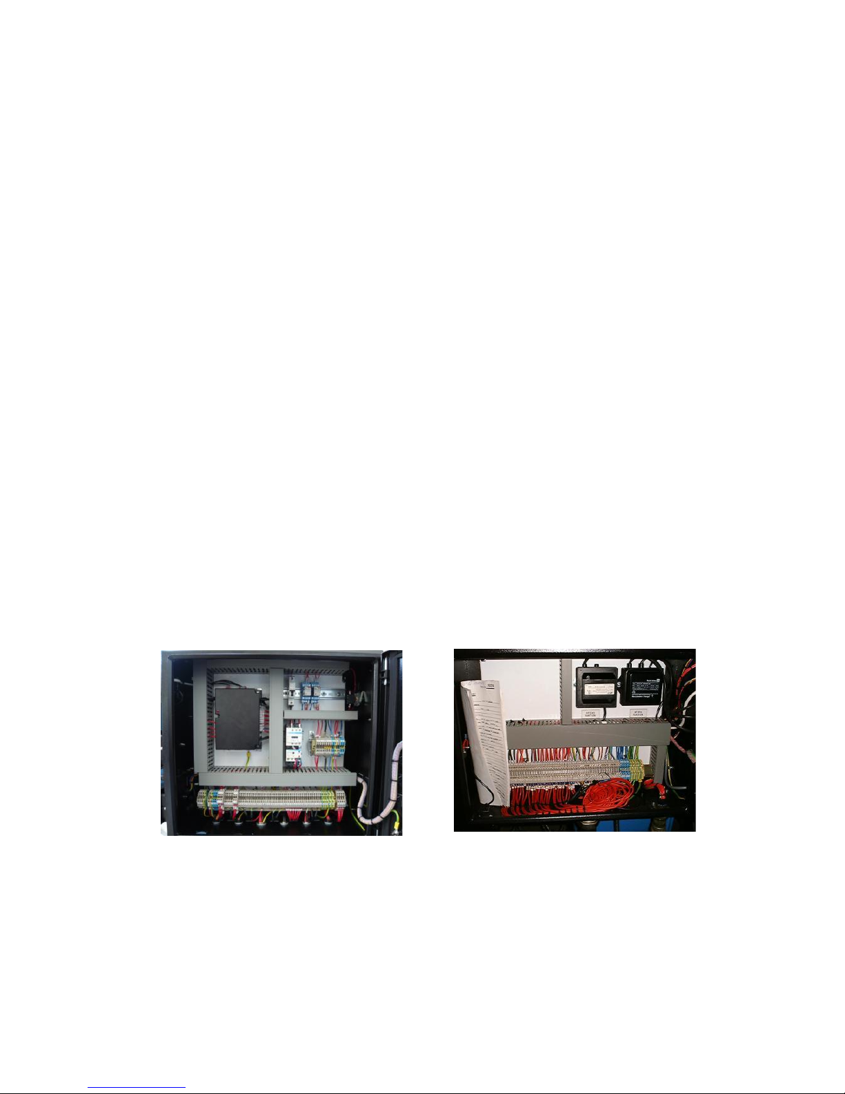
Burner Control Cabinet
Standard burners are supplied with a dust resistant damp-proof cabinet mounted on the side of the
burner. In many cases all the burner controls are fitted within the burner control cabinet (figure 1).
In more complicated installations, this cabinet would house a terminal strip (figure 2) which would
then interface to a control desk via flying leads.
Page 11
Operating Instructions For TD/TAD4 Dual Fuel Burner
June 13 11 of 165 TD/TAD4 Manual Rev 4
Figure 3
Figure 4
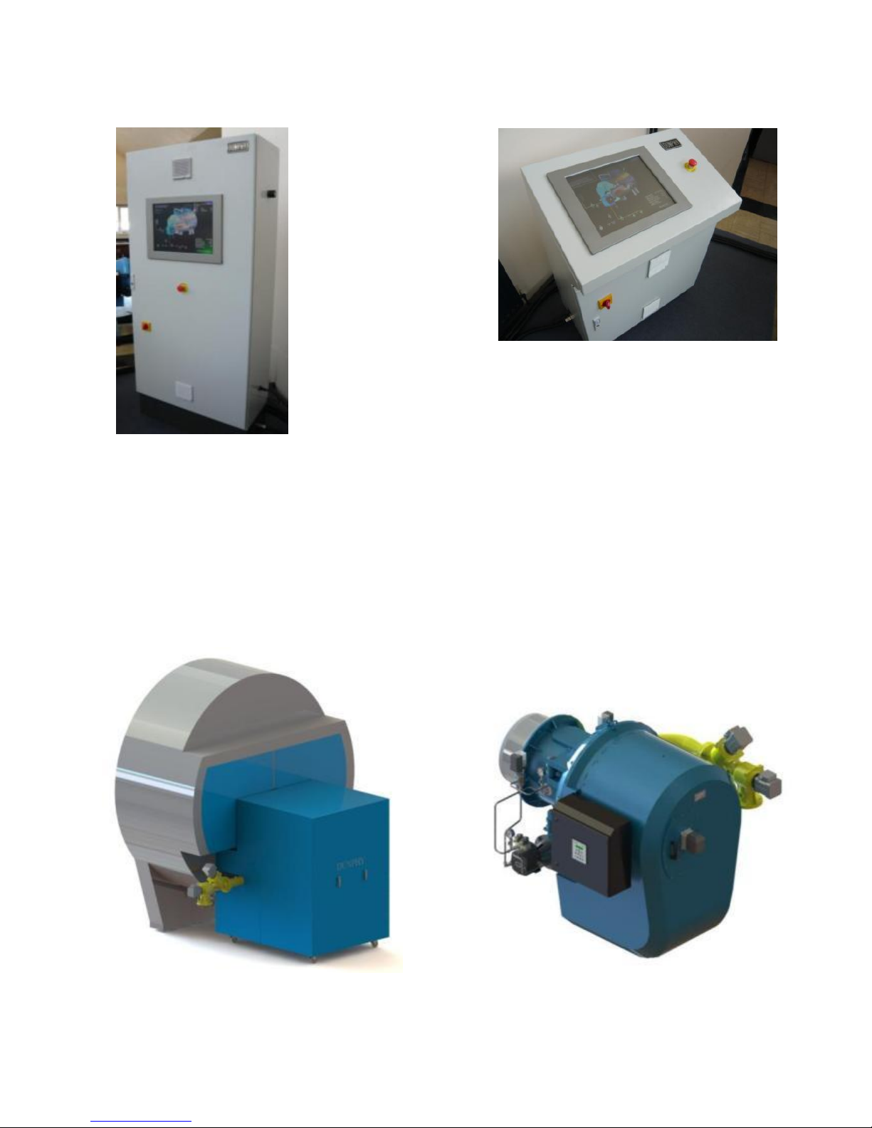
Control desks are available in ‘wardrobe’ type style (figure 3) or ‘desk’ type style (figure 4). These
can vary in complexity and are able to house a whole host of burner/boiler controllers, water levels
controls, inverters, plc etc...
Air Inlet Silencer
Because of their design characteristics, 'T' series burners operate at very low noise levels, however,
further reduction of these levels can be made by fitting air inlet silencers which are designed to
cover the air shutter castings. The standard foam lined silencer typically offers sound levels in the
region of 80dBA. An optional ‘Snorkel’ type silencer is available which will reduce sound levels to
below 75dBA. Silencers can also be tailored to suit ducted air supplies, filters or additional acoustic
attenuation. For extremely sensitive installations, 'Acoustic Shrouds' which cover the entire burner
can be individually designed to suit most applications. Quotations are available on request.
Typical Acoustic Shroud Burner fitted with 'Snorkel' Silencer
Page 12
12 of 165
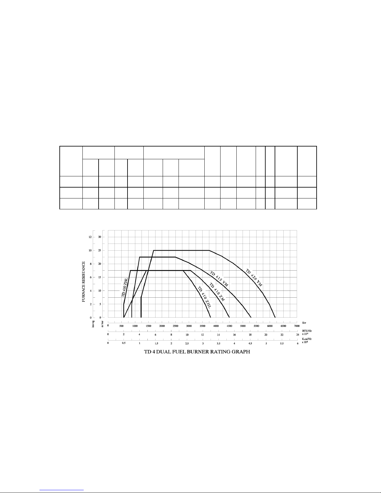
1.5 Burner details and power curve
*1 – Based on Nat. Gas C.V 10.4 kW/m3
*2 - Fitted with a Ratiotronic 6000 System
BURNER
Firing Rate kW
GAS
VOLUME
(m3/HR)*1
FIRING MODE OPTIONS
Fan
Motor
KW
Pump
Motor
kW
Voltage
Hz
Ph
Running
Current
Starting
Current
TYPE
MIN
MAX
MIN
MAX
Mod
Gas
High /
Low Oil
High /
Low
Electronic
Modulation
*2
TD410Z
600
4500
58
433
7.5
2.2
380-420
50 3 23 Amp
48 Amp
TD415Z
800
5300
77
510
11.0
2.2
380-420
50 3 32 Amp
64 Amp
TD420Y
1250
6200
120
596
15.0
2.2
380-420
50 3 39 Amp
88 Amp
Page 13
13 of 165
1.6 General arrangement details
1.6.1 High low/modulating burners on gas, high low on oil
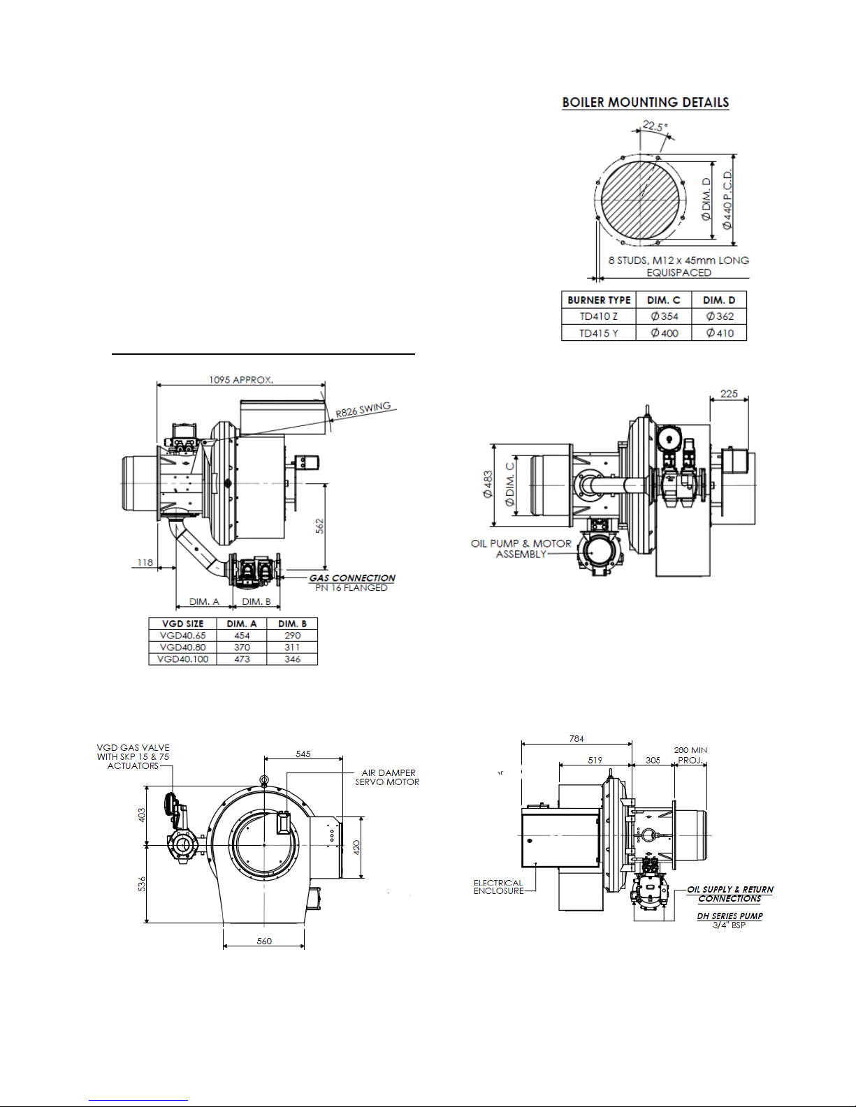
High Low and Pneumatic Modulation burners both use air/gas
ratio valves (details can be found in the component section of this
manual). They have built-in governors thus not requiring an
external governor for gas pressures up to 350mbar.
In this configuration the gas valve requires two signals from the
burner - the air pressure of the burner and furnace resistance of the
boiler. The furnace resistance is monitored with a stainless steel
piece of pipe which is projected into the furnace along the side of
the burner head. This will require an additional hole or notch in the
boiler mounting plate to accommodate – see mounting detail.
TD410 - 415 Burners with VGD40 Gas Valve
Page 14
Operating Instructions For TD/TAD4 Dual Fuel Burner
June 13 14 of 165 TD/TAD4 Manual Rev 4
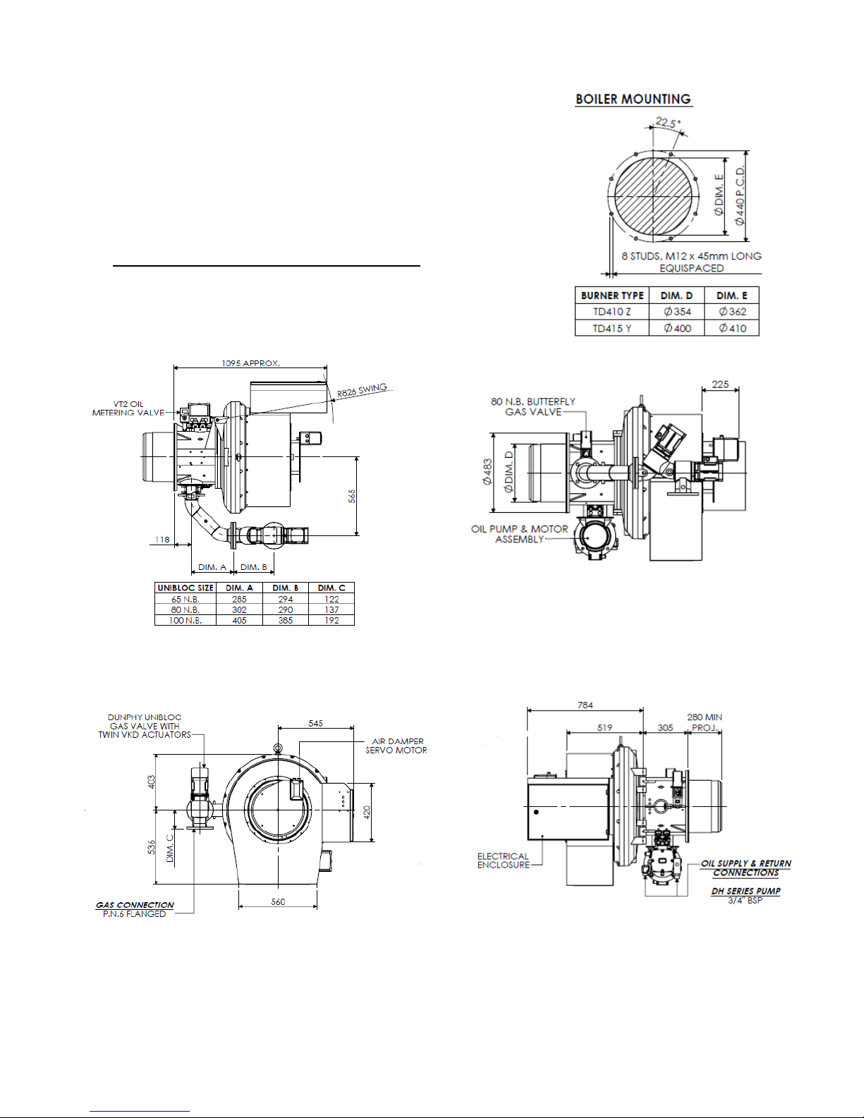
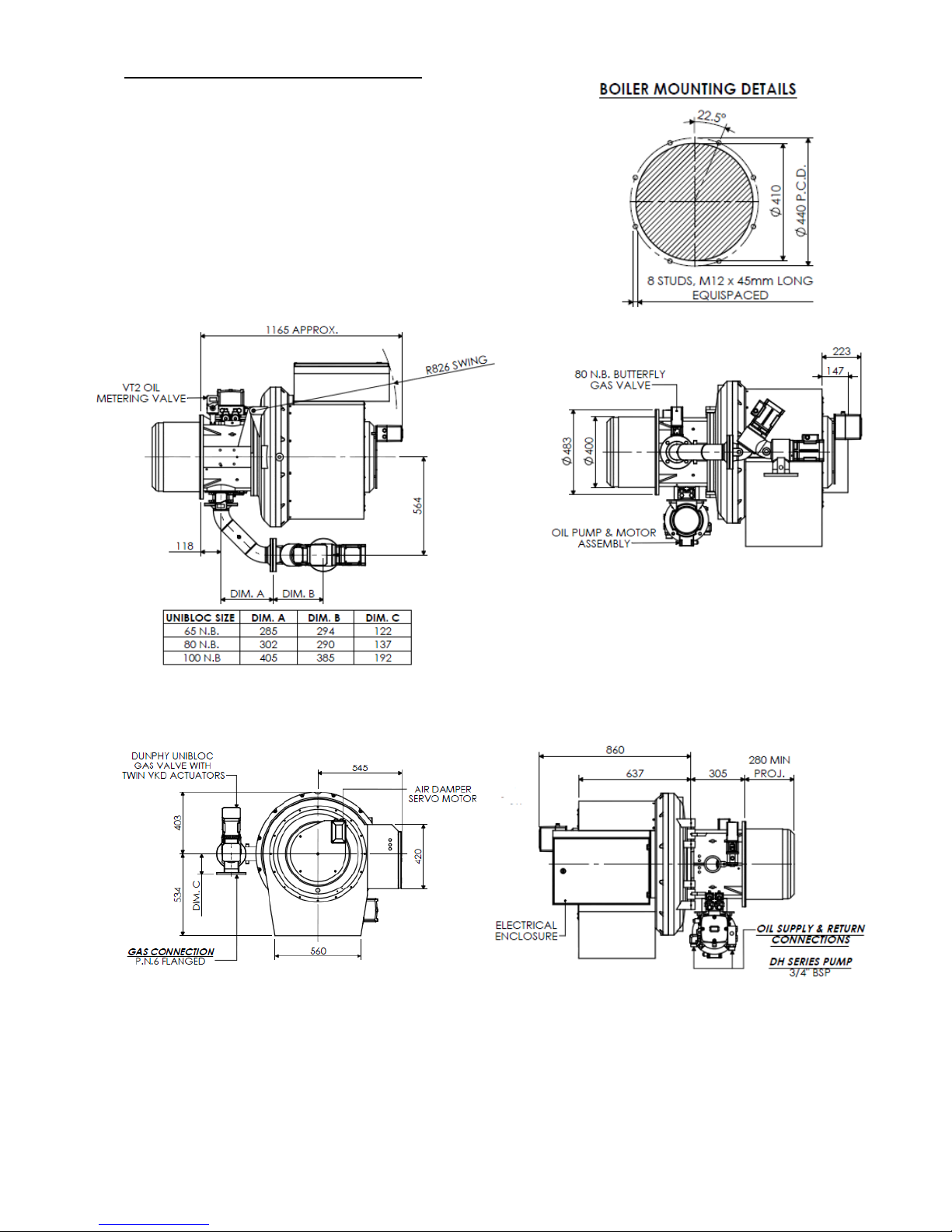
1.6.2 Electronic modulation burners (M RT)
Electronic modulation burners are fitted with on/off gas valves and
electronically controlled butterfly valves for the gas regulation. The
gas valve is generally a Unibloc (see component section for details)
however other valves can also be used depending on site details or
customer preference. An additional electronically controlled oil
metering valve is fitted for oil regulation – see principle of
operation section for more details.
TD410 - 415 Burners with Unibloc Gas Valve
Page 15
Operating Instructions For TD/TAD4 Dual Fuel Burner
June 13 15 of 165 TD/TAD4 Manual Rev 4
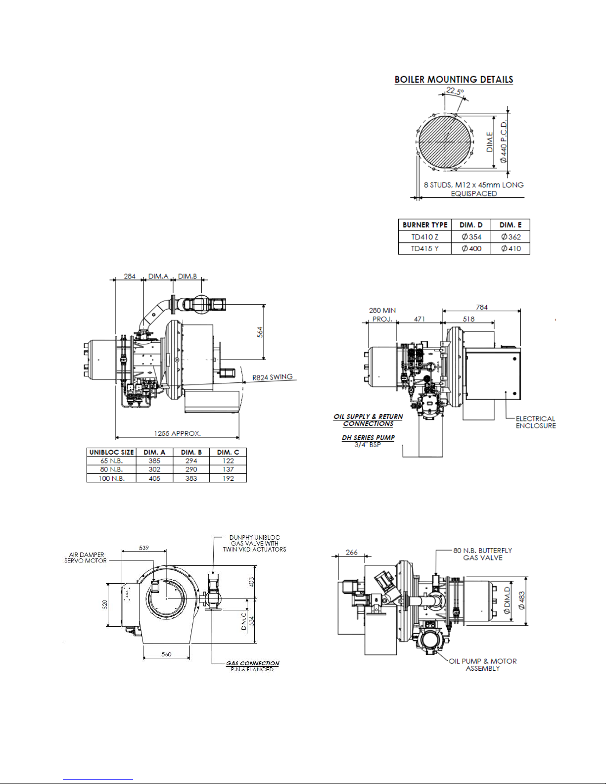
TD420 Burners with Unibloc Gas Valve
Page 16
Operating Instructions For TD/TAD4 Dual Fuel Burner
June 13 16 of 165 TD/TAD4 Manual Rev 4
1.6.3 TD10-415 Multi – Fuel Low Nox Burner General Arrangement
Page 17
Operating Instructions For TD/TAD4 Dual Fuel Burner
June 13 17 of 165 TD/TAD4 Manual Rev 4
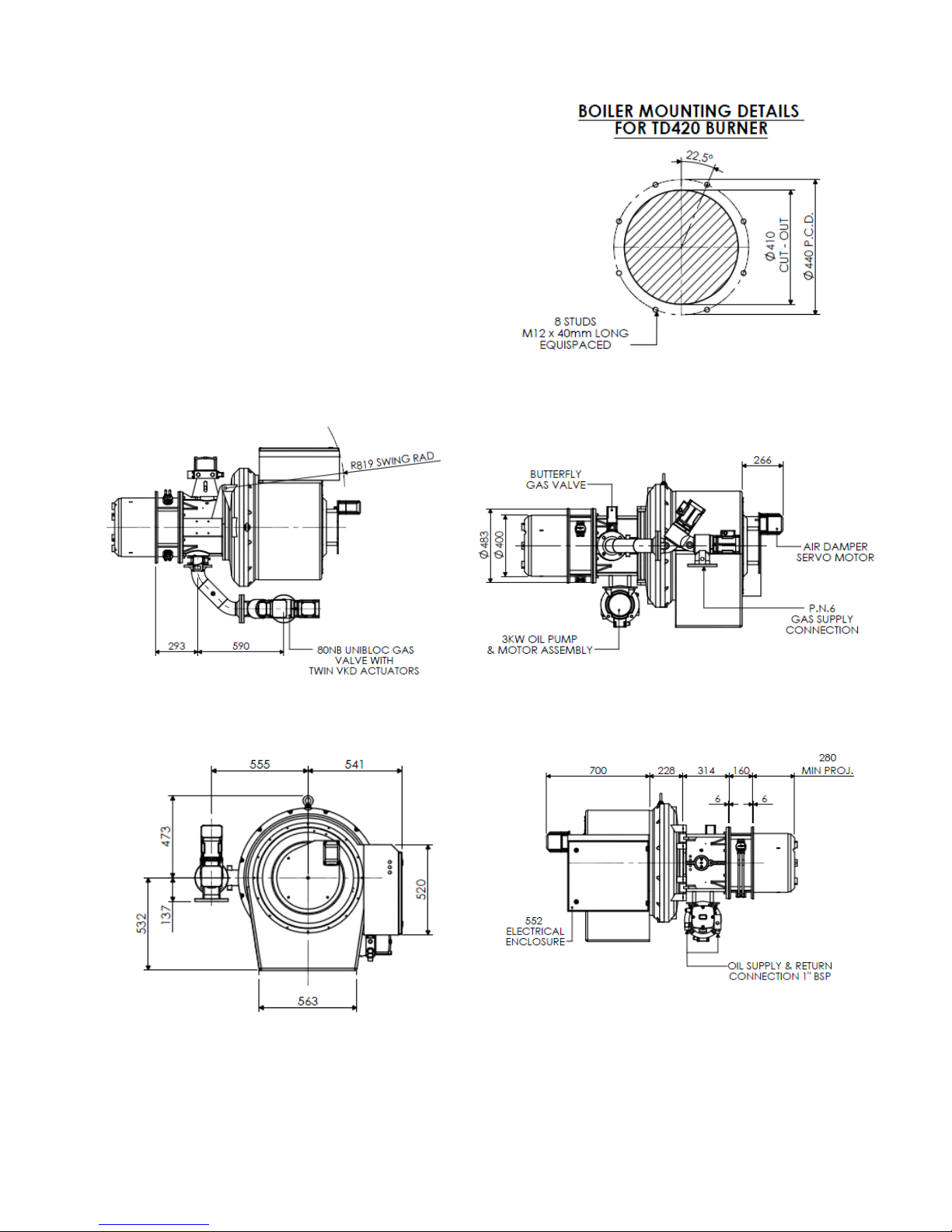
1.6.4 TD420 Multi – Fuel Low Nox Burner General Arrangement
Page 18
Operating Instructions For TD/TAD4 Dual Fuel Burner
June 13 18 of 165 TD/TAD4 Manual Rev 4
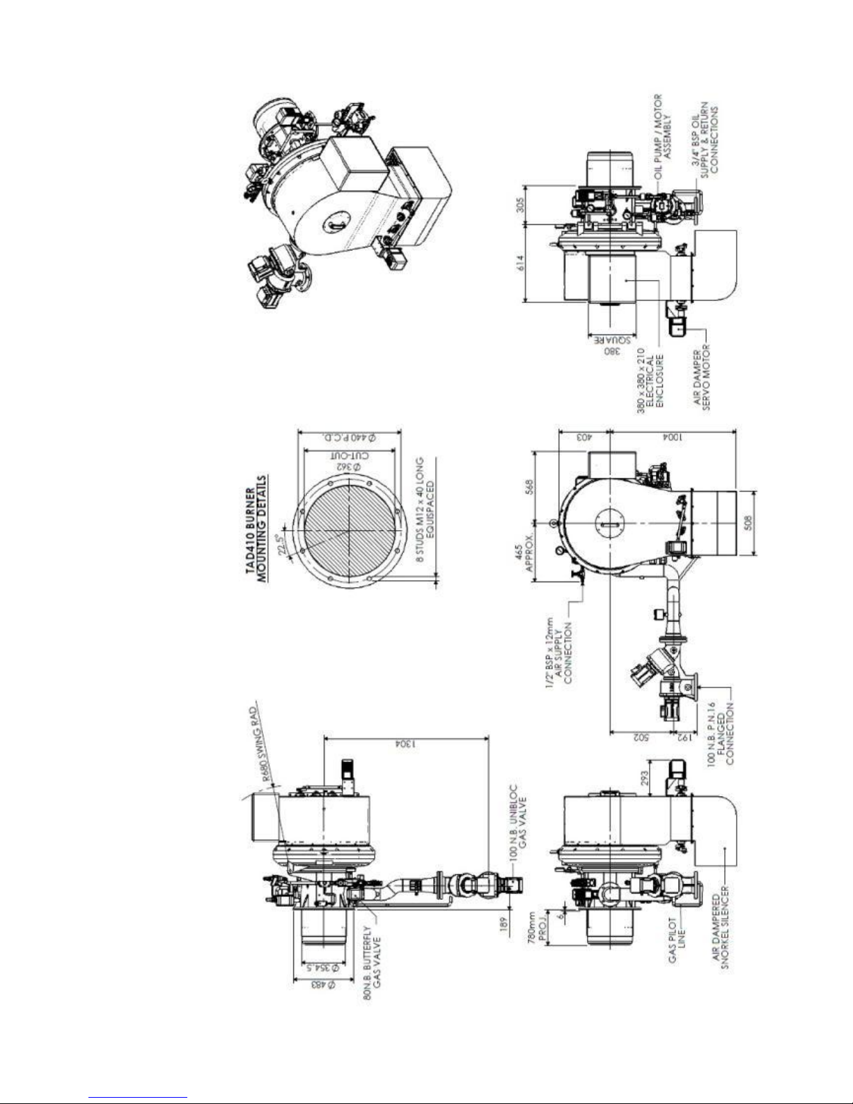
1.6.5 TAD420 Multi – Fuel Low Nox Burner General Arrangement
Page 19
Operating Instructions For TD/TAD4 Dual Fuel Burner
June 13 19 of 165 TD/TAD4 Manual Rev 4
2 Installation
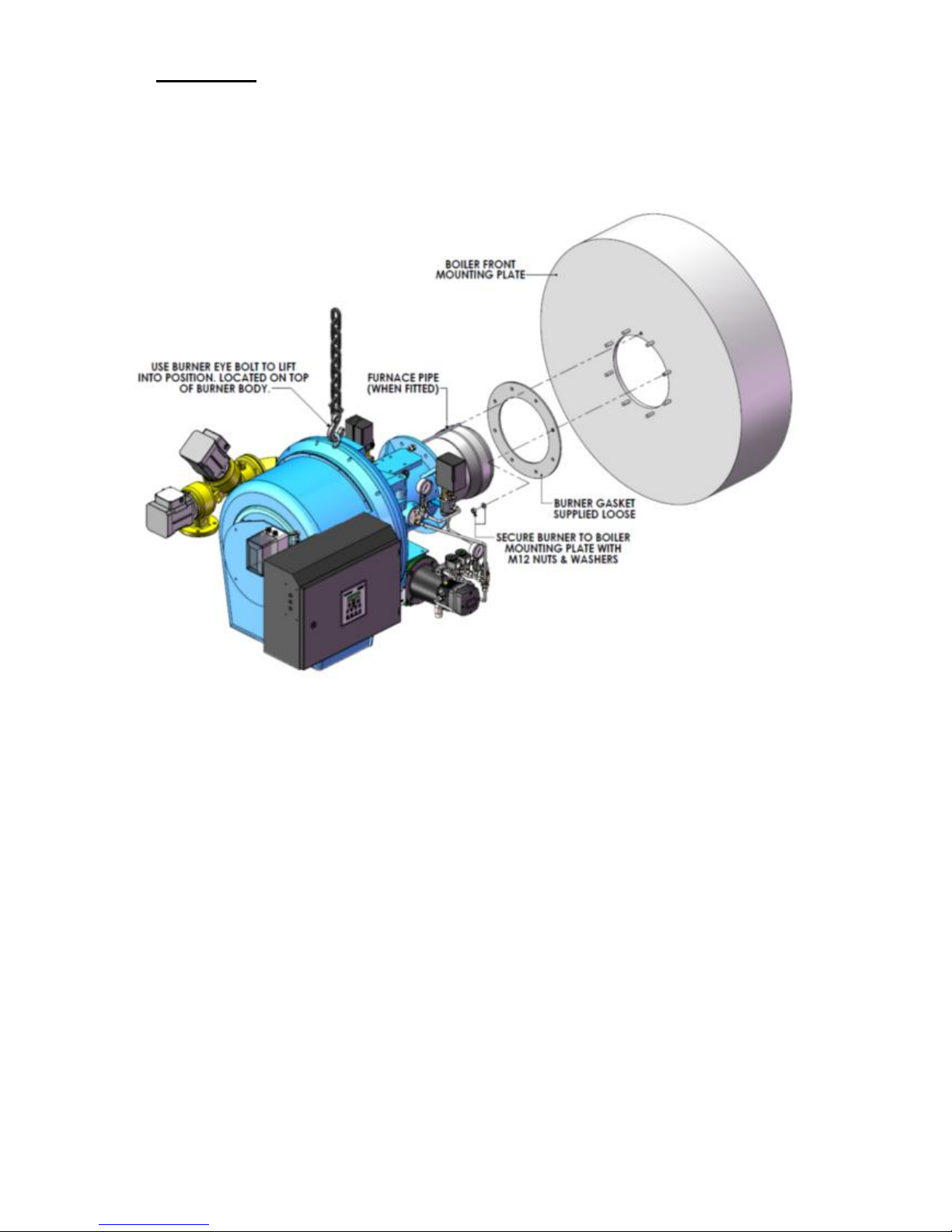
2.1 Burner Mounting
Care must be taken when mounting the burner not to damage the mounting gasket. The furnace
pipe (where fitted) is generally positioned at 12 o’clock on the mounting flange and care must be
taken not to damage it during the mounting process.
Note: - Ensure that the burner mounting gasket is correctly fitted when fixing the burner to
the appliance. This gasket creates a gas-tight seal between the boiler and burner and also
insulates the burner mounting casting.
It is important to check that the burner draught tube projection into the combustion chamber
conforms to the appliance manufacturers instructions.
Non standard draught tube projections are available on request; - please consult the Dunphy sales
dept.
In general, for reverse flame boilers the draught tube projection into the combustion chamber
should be between 50 and 100mm. For other boilers the burner draught tube should finish flush or
slightly proud of any boiler refractory or insulation. Low NOx heads should be projected into the
furnace by at least 100 - 150mm.
If there is any doubt about the correct projection into the combustion chamber, the appliance
manufacturer must be consulted.
Page 20
Operating Instructions For TD/TAD4 Dual Fuel Burner
June 13 20 of 165 TD/TAD4 Manual Rev 4
2.2 Gas Valve mounting
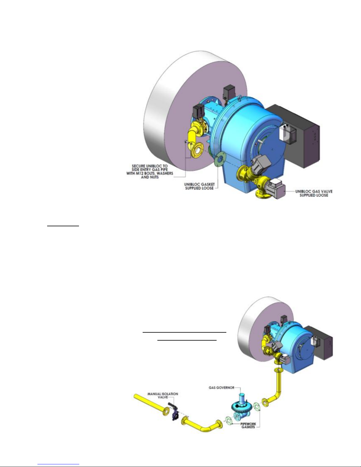
2.2.1 Burner fitted with Unibloc
The Unibloc gas valve is
a heavy item and will
require two persons to lift
it into position and secure
in place using bolts
provided.
The Unibloc is shipped
pre - connected. Please
consult electrical wiring
diagram for electrical
connections.
Governor shown is
supplied with every
burner using a Unibloc
gas valve and should be
installed according to
guidelines illustrated
below and approximately
10 pipe diameters
upstream of the gas valve.
Pipe work and isolating valve are supplied by others.
Important:
The installer must install a 90° turn type isolation ball valve next to or in close proximity to
the burner and capable of rapid operation.
The manual valve must be capable of operating at a pressure equal to 1.5 times the maximum
supply pressure and where possible must be orientated in such a way that when the valve closes the
handle must fall from the vertical to the horizontal. The valve must have mechanical end stops to
prevent the ball valve from going below the 0° point or above the 90° point.
The gas supply pipework
must be adequately
supported to prevent undue
stress on the burner casing or
the gas train components.
Gas supplies greater than
500mbar must be governed
down to a suitable gas
pressure below 500mbar
using a CE approved high
pressure gas governor. The
gas governor or should be
fitted as per manufactures
instructions, copies available
on request.
Typical Gas train installation
is shown on the right
Page 21
Operating Instructions For TD/TAD4 Dual Fuel Burner
June 13 21 of 165 TD/TAD4 Manual Rev 4
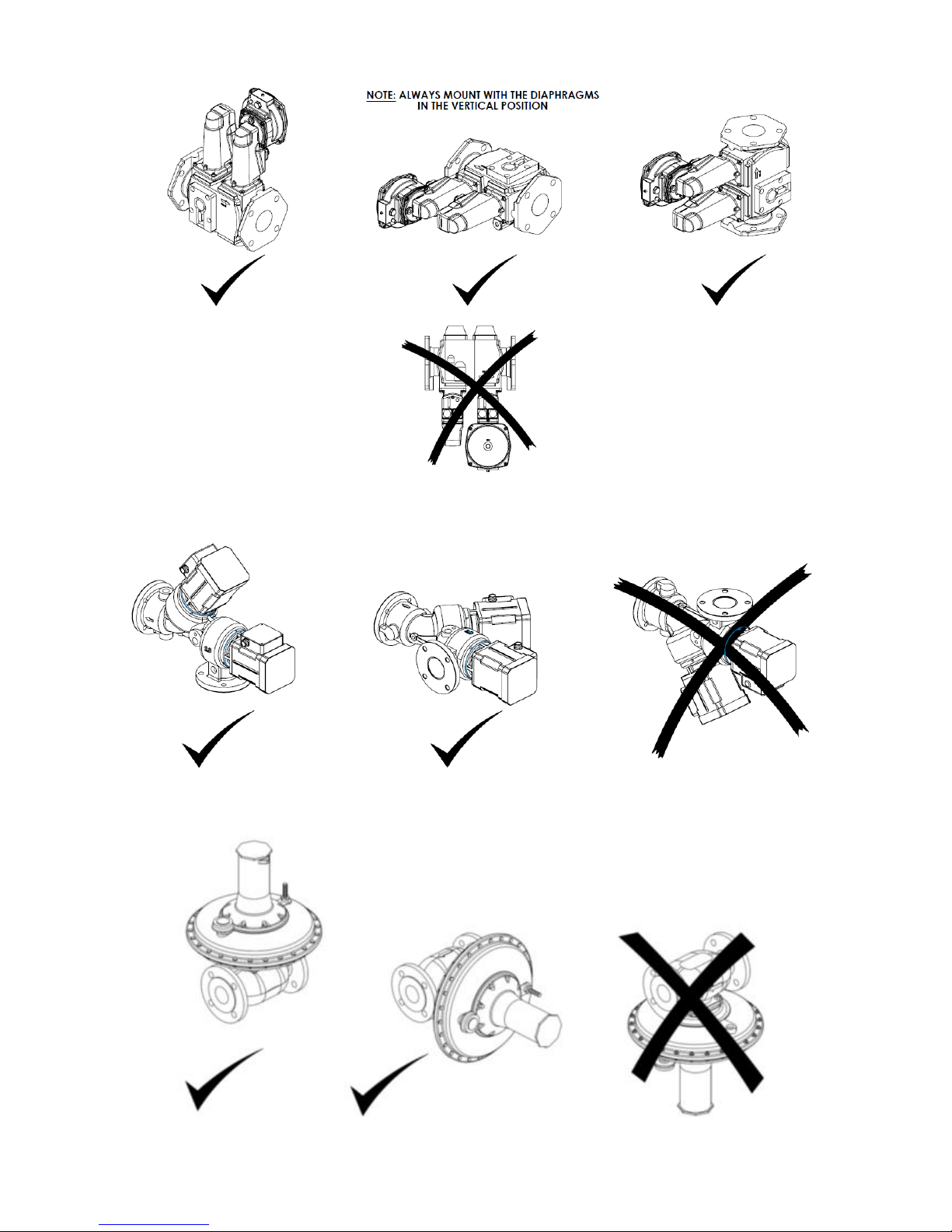
VGD Gas Valve Orientation
Unibloc Orientation
Governor Orientation
Fit governor in accordance with manufactures instructions.
Page 22
Operating Instructions For TD/TAD4 Dual Fuel Burner
June 13 22 of 165 TD/TAD4 Manual Rev 4
With the gas isolation valve next to the burner closed, a pressure test should be carried out on the
main gas supply pipe work and all connections checked with a suitable, non corrosive leak
detection fluid.
If the installation is supplied with a gas pressure above 1 bar (14.5p.s.i.g.) and contains plant with a
heat input of more than 2MW, local authorities will generally ask for the fitting of remotely
operable fire valves. The national or other standards in countries to which the burners may be
exported must be identified and met.
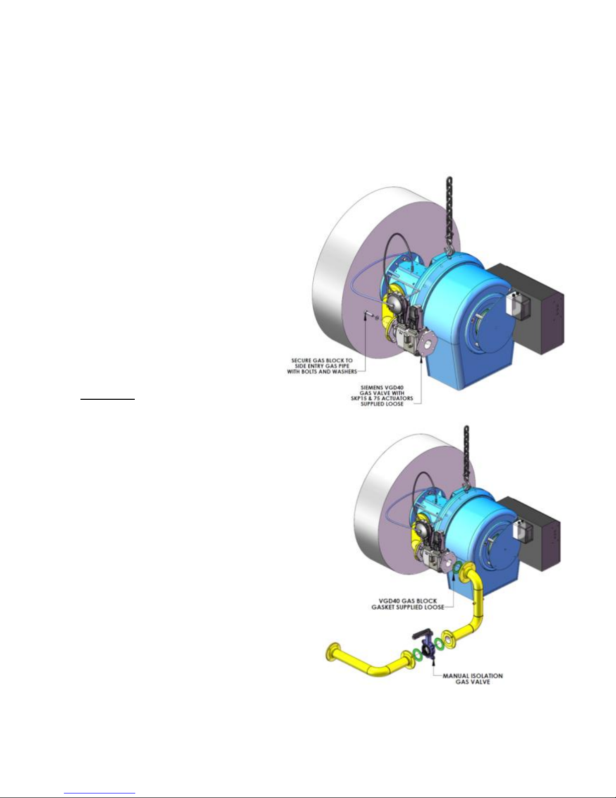
2.2.2 Burner fitted with Siemens VGD40 gas valve
The Siemens gas valve is a heavy item
and will require two persons to lift it into
position and secure in place using bolts
provided.
8mm blue and black PVC pipes plus
fitting are supplied with the burner. The
blue line must be connected between the
“Air” connection on the SKP75 actuator
and the air pulse line situated on the top
flat of the burner hinge section. The black
line must be connected between the
“Combustion Chamber” connection on the
SKP75 and the furnace line connection
protruding through the mounting flange of
the burner.
Important:
The installer must install a 90° turn type
isolation ball valve next to or in close proximity
to the burner and capable of rapid operation.
The manual valve must be capable of operating at
a pressure equal to 1.5 times the maximum supply
pressure and where possible must be orientated in
such a way that when the valve closes the handle
must fall from the vertical to the horizontal. The
valve must have mechanical end stops to prevent
the ball valve from going below the 0° point or
above the 90° point.
The gas supply pipework must be adequately
supported to prevent undue stress on the burner
casing or the gas train components.
The Siemens gas valve has a built-in governor and
is suitable for gas pressures up to 500mBar.
Gas supplies greater than 500mbar must be
governed down to a suitable gas pressure below
500mbar using a CE approved high pressure gas governor. The gas governor or should be fitted as
per manufactures instructions, copies available on request.
Page 23
Operating Instructions For TD/TAD4 Dual Fuel Burner
June 13 23 of 165 TD/TAD4 Manual Rev 4
2.3 Fuel oil installations
Fuel oil installations must comply with the following British Standards or equivalent local, national
or international standards.
BS799 Oil burning equipment
BS5410 Code of practice for oil firing
BS2869 Fuel oils for non marine use
Installations must conform to local Bye-laws and regulations which should be identified by
application to the local planning authority.
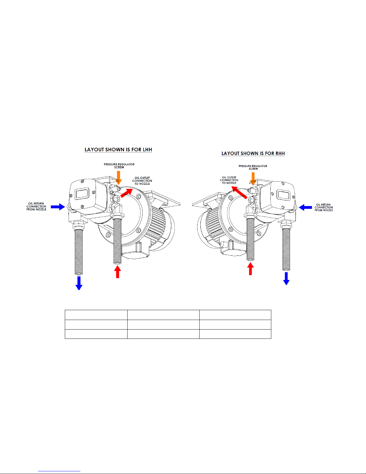
2.3.1 Pump Connections
The burner is supplied with two flexible hose lines and is connected as shown in illustration below.
PUMP TYPE
CONNECTION A
CONNECTION B
DH1 Series
3
/4" BSP
3
/4" BSP
DH2 Series
1” BSP
1” BSP
2.4 Pump Priming
In order to ensure correct start-up for DH series oil pumps, the following guidelines should be
adhered to.
1. Ensure that the oil supply to the pump has been properly bled through and that no air is
present in the oil supply. The flexible oil lines should be fully flooded before connection to
the pump.
2. Check that all isolating valves are open and that the oil supply temperature and pressure are
correct.
3. Lubricate the pump by removing the pressure gauge plug and filling the pump with suitable
thin lubricating oil.
4. Check pumps rotation.
OIL RETURN FLEXIBLE
CONNECTION B
OIL RETURN FLEXIBLE
CONNECTION B
OIL RETURN FLEXIBLE
CONNECTION A
OIL RETURN FLEXIBLE
CONNECTION A
Page 24

Operating Instructions For TD/TAD4 Dual Fuel Burner
June 13 24 of 165 TD/TAD4 Manual Rev 4
Warning:
Touching the electrical parts may be fatal – even after the equipment has been
disconnected from mains.
Also make sure that other voltage inputs have been disconnected, such as
load-sharing (linkage of DC intermediate circuit), as well as the motor
connection for kinetic back-up.
Before touching any electrical parts, wait at least: please consult the inverter
manual.
5. Turn pump slow until all air has been vented both from the pump itself and the burner
pipework, and the system is fully flooded.
6. The pump can now be put into operation.
2.5 Gas installation
Note: The national or other standards in countries to which the burner may be exported to must be
identified and adhered to.
2.6 Electrical connections
All electrical installation work must be carried out in accordance with the I.E.E. wiring regulations
17th Edition 2008, with further reference to the Health and Safety Executives `Memorandum of
Guidance on the Electricity at Work Regulations 1989 ( H.S.E. Booklet HS[R]25 )
Take note of the I.E.E. requirement for bonding main gas supply pipework to earth.
Connections to all terminals and the appliance should be made in accordance with the wiring
diagram supplied with each burner.
The final part of the electrical cable run must be made in flexible conduit, long enough to enable
the appliance door to be opened.
Ensure that the mains electrical supply to the burner is protected by a suitably sized fuse.
Connections to all terminals and the appliance should be made in accordance with the wiring
diagram supplied with each burner, using suitable fixed wiring installation (incorporating means of
disconnection) in accordance with local and national wiring regulations.
2.7 Inverter Connection
Burner motor connections can be found in dedicated aluminium enclosure situated on the side of
the burner control panel. Wiring diagram shows how to connect the inverter to this enclosure. The
earth leakage current from the frequency converter exceeds 3.5mA. To ensure excessive leakage
current conforms to EN/IEC 61800-5-1, an earth wire of at least 10mm2 or two separate earth
ground wires are used.
2.8 Ventilation requirements
In all cases, gas installation work must be carried out by approved members of
Gas Safe
All relevant standards of The British Standards Institute, IGEM Standard's
and the equivalent European Standards must be adhered to.
Page 25

Operating Instructions For TD/TAD4 Dual Fuel Burner
June 13 25 of 165 TD/TAD4 Manual Rev 4
Provision must be made for an adequate supply of combustion and ventilating air to be available
when all access doors, fire doors and windows are closed. Air supply fans or flue dilution systems
must be interlocked to prevent operation of the burner(s) in the event of fan failure or shutdown.
To ensure an adequate supply of combustion air, the room in which the burner(s) are installed
should have permanent ventilation according to local or national standards.
Page 26

Operating Instructions For TD/TAD4 Dual Fuel Burner
June 13 26 of 165 TD/TAD4 Manual Rev 4
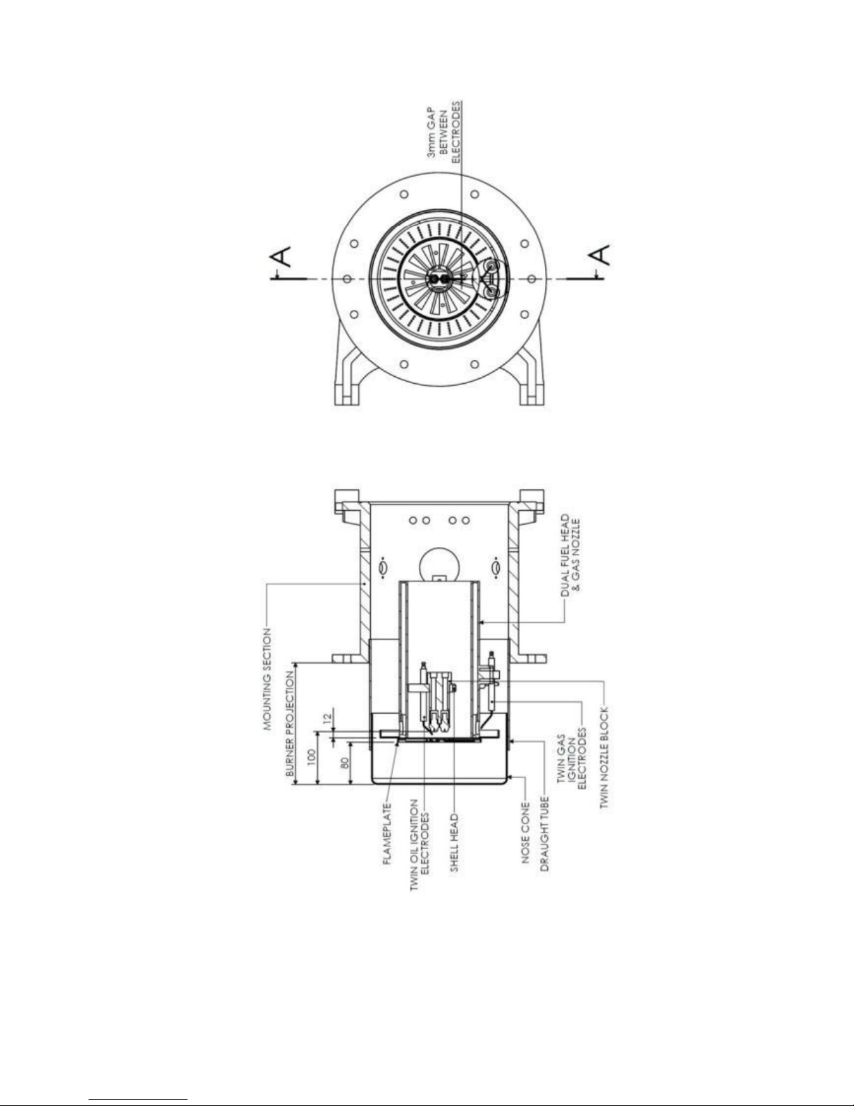
3 Combustion Head Settings
On burners fitted with standard 'Z' and 'Y' type nose cones, the dimension 'A' between the end of
the burner nose cone and the front face of the flame plate, can be altered by releasing the three, M6
locking nuts inside the draught tube, and sliding the cone forwards / backwards, along its
adjustment slots until the required setting is obtained.
Important Notes:
Factory setting of gas flow is as shown on the following combustion head arrangement
drawings. Position of gas nozzles must be finalised at commissioning to suit the particular
boiler in which the burner is fitted.
When using low NOx heads, the projection must be at least 130-150mm past the boiler
refractory (into the furnace).
Page 27
Operating Instructions For TD/TAD4 Dual Fuel Burner
June 13 27 of 165 TD/TAD4 Manual Rev 4
3.1 High / Low Burners
Page 28
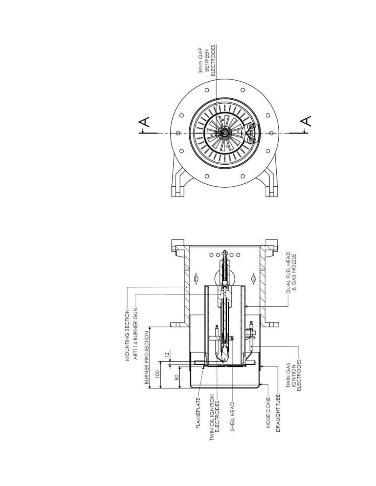
Operating Instructions For TD/TAD4 Dual Fuel Burner
June 13 28 of 165 TD/TAD4 Manual Rev 4
3.2 Modulating Burners
Page 29
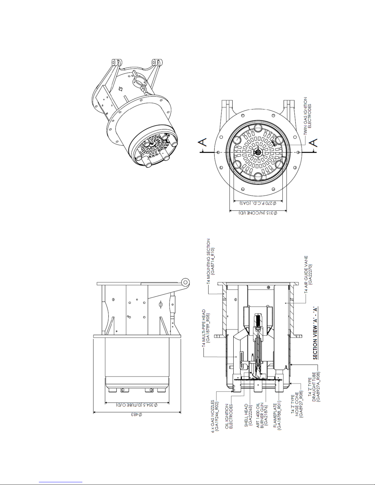
Operating Instructions For TD/TAD4 Dual Fuel Burner
June 13 29 of 165 TD/TAD4 Manual Rev 4
3.3 Modulating TD410 Burners Fitted With Low NOx Multi-Pipe Gas Head
Page 30
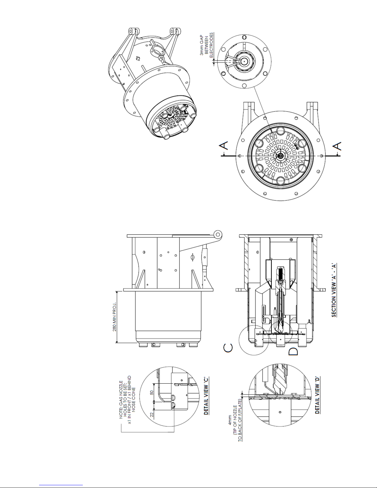
Operating Instructions For TD/TAD4 Dual Fuel Burner
June 13 30 of 165 TD/TAD4 Manual Rev 4
Page 31
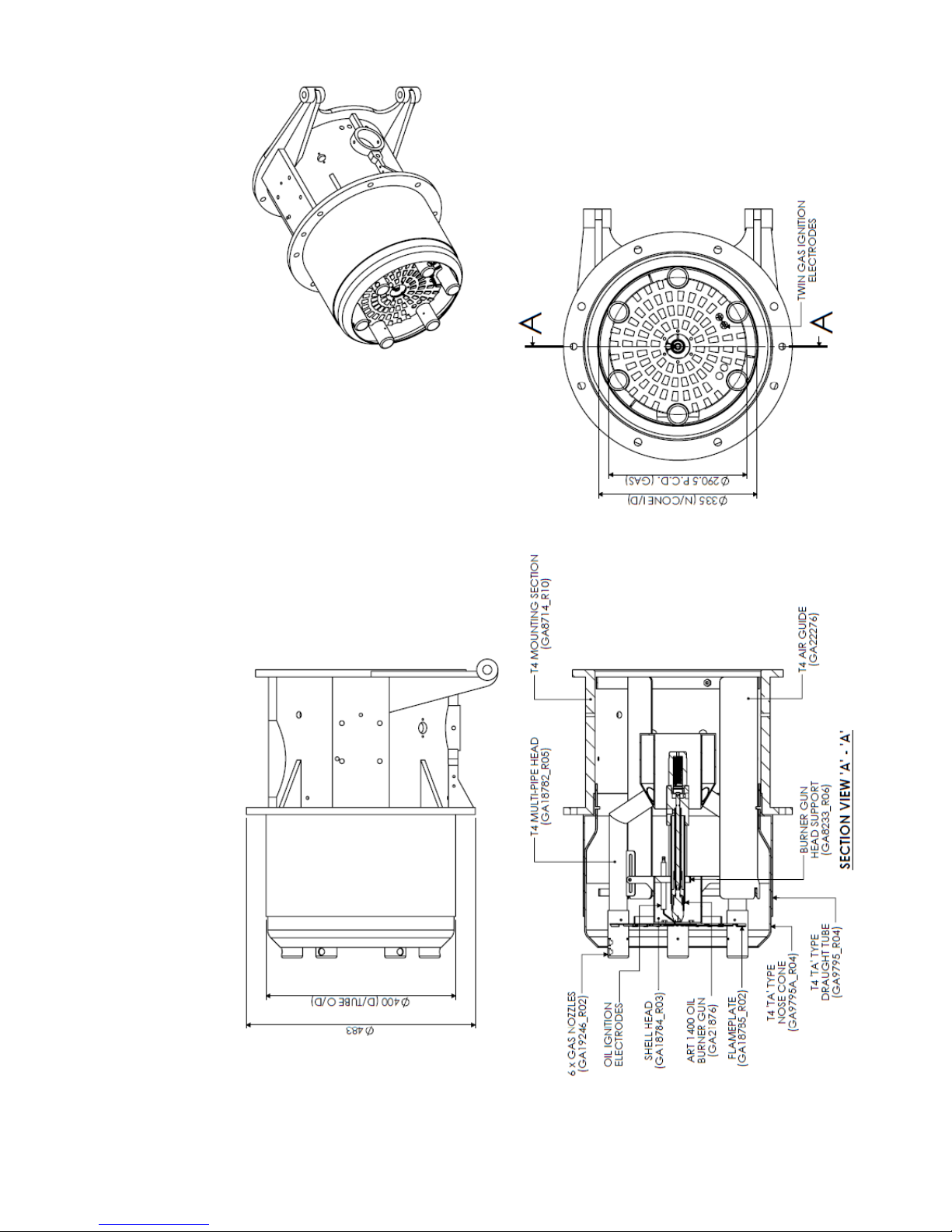
Operating Instructions For TD/TAD4 Dual Fuel Burner
June 13 31 of 165 TD/TAD4 Manual Rev 4
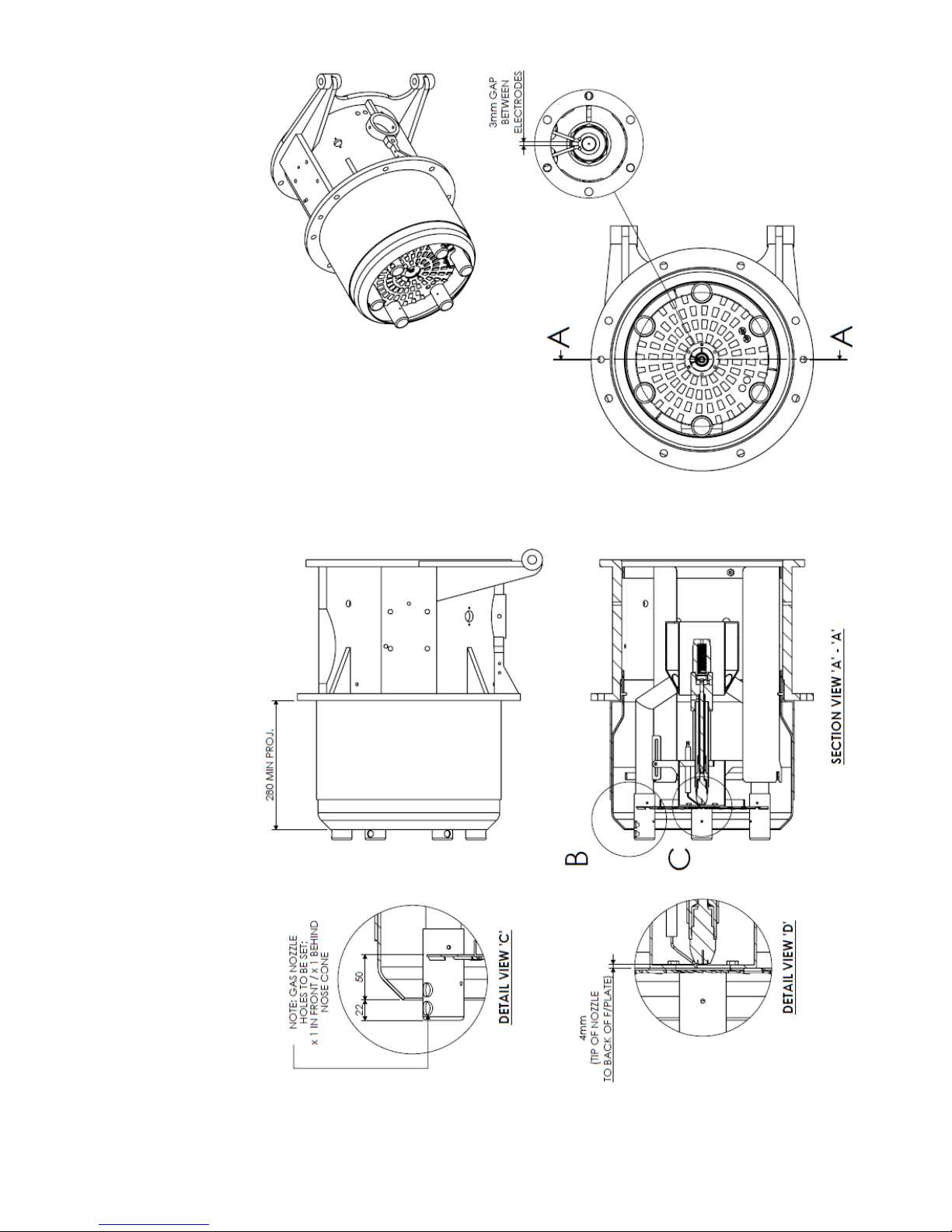
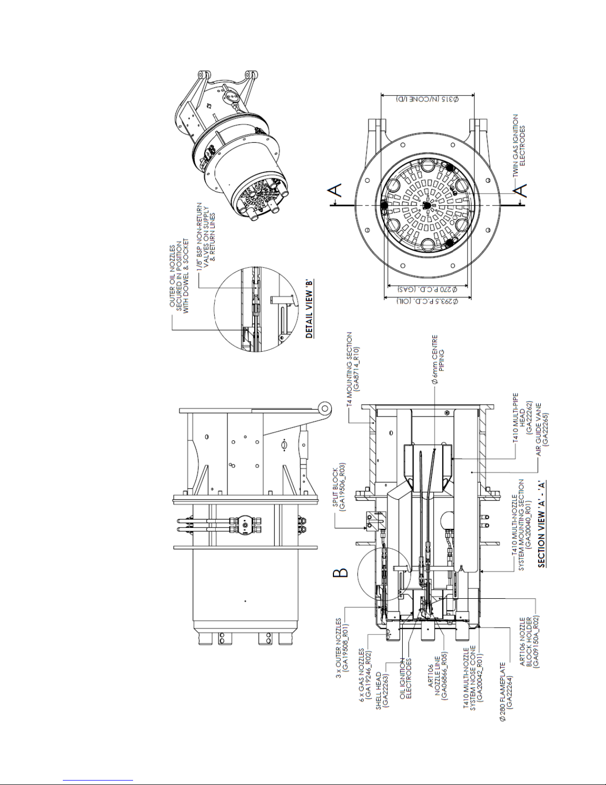
3.1 Modulating TD415-420 Burners Fitted With Low NOx Multi-Pipe Gas Head
Page 32
Operating Instructions For TD/TAD4 Dual Fuel Burner
June 13 32 of 165 TD/TAD4 Manual Rev 4
Page 33
Operating Instructions For TD/TAD4 Dual Fuel Burner
June 13 33 of 165 TD/TAD4 Manual Rev 4
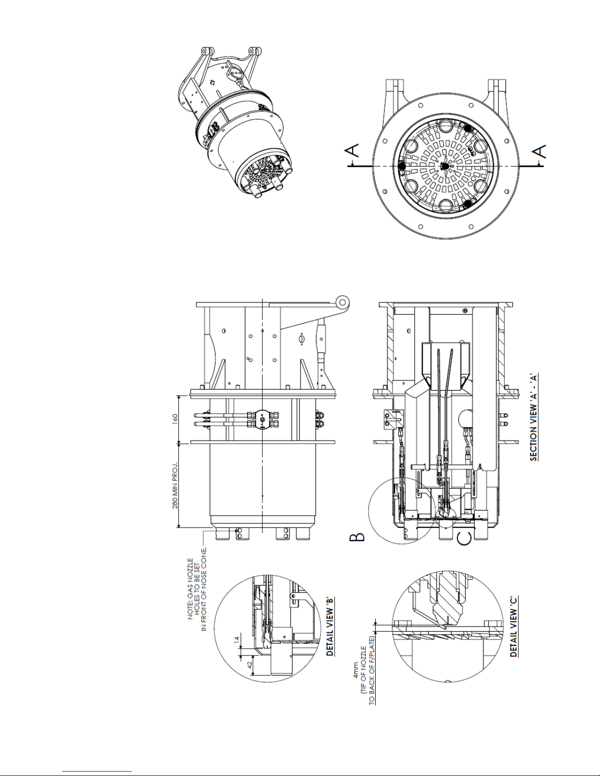
3.2 Modulating TD410 Burners Fitted With Low NOx Multi-Pipe Gas Head & Multi-Oil
Page 34
Operating Instructions For TD/TAD4 Dual Fuel Burner
June 13 34 of 165 TD/TAD4 Manual Rev 4
Page 35
Operating Instructions For TD/TAD4 Dual Fuel Burner
June 13 35 of 165 TD/TAD4 Manual Rev 4
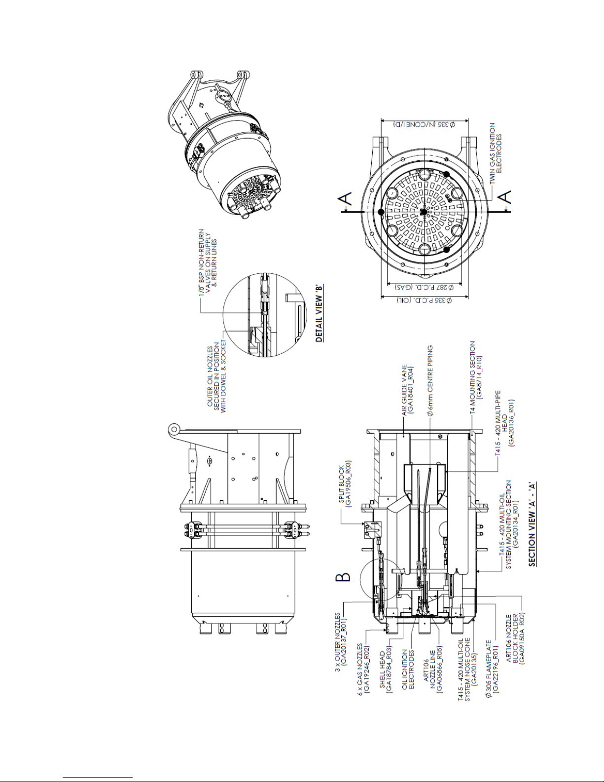
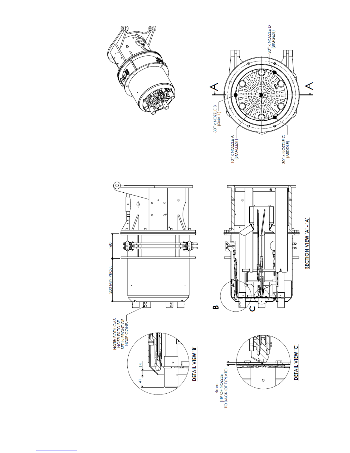
3.1 Modulating TD415-420 Burners Fitted With Low NOx Multi-Pipe Gas Head & Multi-
Oil
Page 36
Operating Instructions For TD/TAD4 Dual Fuel Burner
June 13 36 of 165 TD/TAD4 Manual Rev 4
Page 37
Operating Instructions For TD/TAD4 Dual Fuel Burner
June 13 37 of 165 TD/TAD4 Manual Rev 4
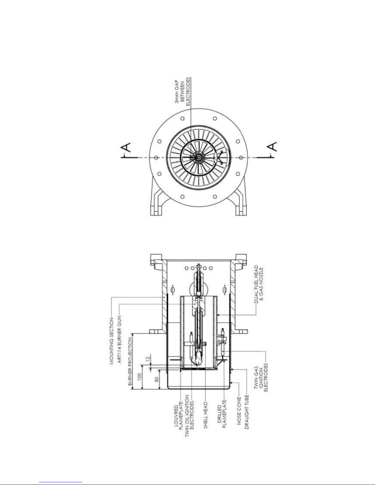
3.2 Modulating Burners Fitted With Bio - Gas Head
Page 38
Operating Instructions For TD/TAD4 Dual Fuel Burner
June 13 38 of 165 TD/TAD4 Manual Rev 4
3.3 Nozzle Adjustment
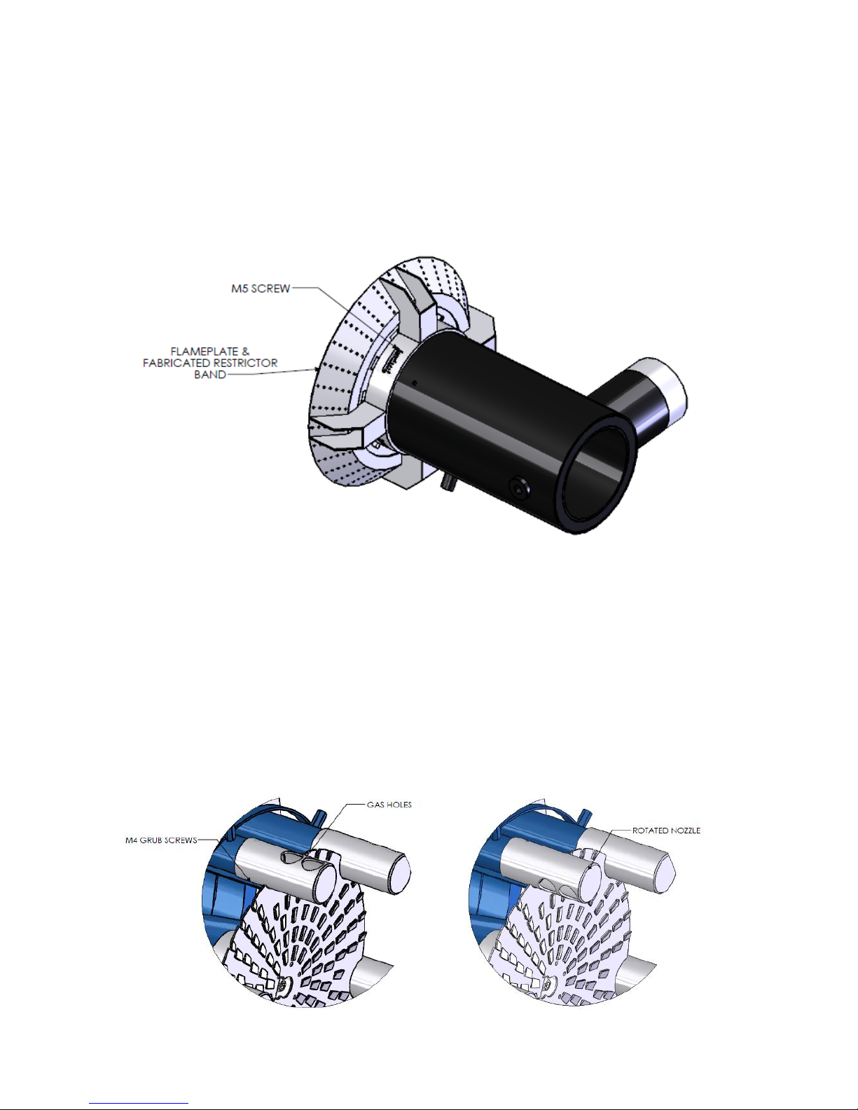
3.3.1 Gas Head
The Combustion head is attached to the gas inlet on the body. The gas flows through the gas annulus
and through the 4 holes in the gas nozzle.
The gas flow can be altered by adjusting the restrictor band, shown below. Undo the four M5 screws,
rotate the band to open or close the nozzle holes.
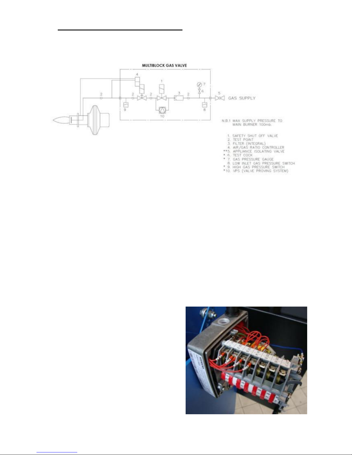
3.3.2 Multipipe Gas Nozzle adjustment
The Combustion head is attached to the gas inlet on the body. The gas flows through the 6 gas pipes and
through the holes in the gas nozzles.
The gas flow can be altered by rotating the nozzles to direct the gas either towards or away from the
centre of the burner.
The gas nozzles can also be adjusted along the multipipe head, this will either move the gas holes closer
or further away from the flameplate.
To carry out the above adjustments, loosen the 2x M4 grub screws on each nozzle securing the nozzle
to the pipe.
Page 39
Operating Instructions For TD/TAD4 Dual Fuel Burner
June 13 39 of 165 TD/TAD4 Manual Rev 4
4 Adjustments and Operating Principles
4.1 High/Low burners (HL)
4.1.1 High / Low Gas
High low control is classed as the simplest form of control for a burner of this size. It relies on a
high/low thermostat monitoring either the temperature or pressure of an appliance which in turn via
the control box will drive the air damper servo between the high fire position and low fire position.
Gas regulation is performed by means of an air/gas ratio valve. The valve senses the amount of
combustion air available and regulates an internal gas governor to output sufficient gas to ensure
good combustion at both high and low firing rates. This also gives the feature of maintaining good
air gas ratio (therefore good efficiency) between high and low fire positions which wouldn’t be the
case on a standard 2 stage gas valve. When the burner is switched off the air damper will fully close
preventing any chimney buoyancy cooling of the appliance. Cam IV of the air servo motor is used
to set the ignition position of the air damper. Once the burner is lit and has stabilised the air damper
will move to either the low fire (CAM III) or high fire (CAM I) position depending on load
demand. Travel is adjusted by means of cam operated limit switches. The cam switch gears within
the motor can be disengaged by pushing the brass push button. Releasing the gears allows
adjustment of the air damper without connection to the drive unit. Adjustments of cams can be
made by hand or with the key which is housed within the motor cover.
Gas flow adjustments are made using the controls
‘V’ (for high fire adjustment) and ‘N’ (for low fire
adjustment) – see commissioning section for
details and gas valve manufacture details shown in
component section.
Cam I………... High Fire Gas
Cam II...............Air Damper Fully Closed
Cam III..............Low Fire Gas
Cam IV..... ........Ignition Position For Gas
Cam V...............High Fire Oil
Cam VI............. Low Fire Oil
Cam VII............V2 Oil
Page 40
Operating Instructions For TD/TAD4 Dual Fuel Burner
June 13 40 of 165 TD/TAD4 Manual Rev 4
4.1.2 High / Low Oil
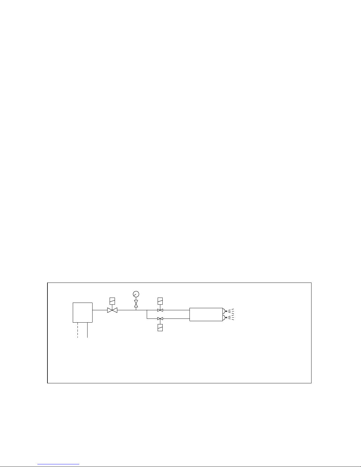
Atomisation of the fuel is by two separate nozzles, one for low fire and the second for high fire.
The oil supply to each nozzle passes through one of twin solenoid shut-off valves and the burner
output is determined by the size of nozzle and the pressure setting of the fuel pump regulator.
Normally, two nozzles of the same size will be used to give a total output equivalent to the
maximum continuous rating (MCR) of the appliance, and, At low fire, approximately 50% of
MCR.
Dissimilar nozzles can however be fitted to alter the low fire to high fire ratio. Nozzles of different
spray angle and patterns are used on various furnace configurations in order to give the appropriate
flame shape. The whole of the oil system is protected by a pump discharge valve ( PDV ) which is
fitted on the oil pressure outlet of the pump and which closes, isolating the oil system when the
burner is not running.
When the control box reaches the firing stage, the air damper drives to the low fire position
(CAM VI) and the ignition spark is switched on.
Both the PDV and first stage solenoid valve (V1) are energised simultaneously releasing oil
through the first stage nozzle, which is ignited by the spark from the ignition electrode.
The oil pressure should now be adjusted, by means of the pump pressure regulating screw, to give
approximately 50% of the MCR of the appliance and the air shutter adjusted to give optimum
combustion efficiency.
As the control box reaches the high fire stage, the air damper motor drives the air shutter to the
high fire position and sends a signal to the second stage oil valve (V2).
As a safety measure, the second stage oil valve is energised through an auxiliary switch in the air
damper motor (CAM VII). The logic of this arrangement is that the air damper must be in the `high
fire` position before the second stage solenoid can open, thus ensuring that an oil rich condition
cannot occur.
When a burner is switched from high to low fire, the closing speed of the solenoid will always be
faster than that of the air damper, so the combustion will again remain air-rich.
The oil pressure should now be adjusted, by means of the pump pressure regulating screw, to give
the full MCR of the appliance and the air shutter adjusted to give optimum combustion efficiency.
Nozzle throughputs are given in the table on the following page.
It is essential that, on completion, the burner is tried a number of times to ensure that changeover
between low and high fire is smooth and that the flame does not `lift off`.
LFN
HFN
V1
V2
GC
PG
PDV
PUMP
P
S
R
OIL SUPPLY
V1
Low Fire Valve NC
V2
High Fire Valve NC
PDV
Pump Discharge Valve
PG
Pressure Gauge
GC
Gauge Cock
LFN
Low Fire Nozzle
HFN
High Fire Nozzle
P
Pump Pressure
S
Suction
R
Return
OIL LINE SCHEMATIC FOR LIGHT OIL DUAL FUEL BURNERS
HIGH LOW WITH TWIN NOZZLES
Page 41

Operating Instructions For TD/TAD4 Dual Fuel Burner
June 13 41 of 165 TD/TAD4 Manual Rev 4
HIGH/LOW BURNERS
NOZZLE PRESSURE/OIL THROUGHPUT TABLES
Rated Flow at
U.S. GALLONS PER HOUR
LITRES PER HOUR
100 P.S.I.
PRESSURE P.S.I.
PRESSURE BAR
G.P.H.
L/hr
125 150 175 200 250 300 350 10 12 14 18 20 25
1.00 3.78 1.12 1.22 1.32 1.41 1.58 1.73 1.87 4.56 5.00 5.39 6.11 6.44 7.20
1.10 4.16 1.23 1.35 1.46 1.56 1.74 1.91 2.06 5.01 5.49 5.93 6.73 7.09 7.93 1.20 4.54 1.34 1.47 1.59 1.70 1.89 2.08 2.25 5.47 5.99 6.47 7.34 7.73 8.64 1.25 4.73 1.40 1.53 1.65 1.77 1.98 2.16 2.34 5.70 6.24 6.74 7.64 8.05 9.00 1.35 5.11 1.51 1.65 1.79 1.91 2.13 2.34 2.53 6.15 6.74 7.28 8.26 8.71 9.73 1.50 5.68 1.68 1.84 1.98 2.12 2.37 2.60 2.80 6.84 7.49 8.09 9.17 9.67 10.8 1.65 6.25 1.84 2.02 2.18 2.33 2.61 2.86 3.09 7.52 8.24 8.90 10.1 10.6 11.9
1.75 6.62 1.96 2.14 2.31 2.47 2.77 3.03 3.27 7.98 8.74 9.44 10.7 11.3 12.6 2.00 7.60 2.24 2.45 2.65 2.83 3.16 3.46 3.74 9.12 9.99 10.8 12.2 12.9 14.4
2.25 8.50 2.52 2.76 2.98 3.18 3.56 3.89 4.20 10.3 11.2 12.1 13.8 14.6 16.3 2.50 9.50 2.80 3.06 3.31 3.54 3.95 4.33 4.67 11.4 12.5 13.5 15.3 16.1 18.0 3.00 11.4 3.35 3.67 3.97 4.24 4.74 5.20 5.61 13.7 15.0 16.2 18.3 19.3 21.6 3.50 13.0 3.91 4.29 4.63 4.95 5.54 6.06 6.55 16.0 17.5 18.9 21.4 22.6 25.2 4.00 15.0 4.47 4.90 5.29 5.66 6.32 6.93 7.48 18.2 20.0 21.6 24.5 25.8 28.9 4.50 17.0 5.03 5.51 5.95 6.36 7.12 7.79 8.42 20.5 22.5 24.3 27.5 29.0 32.4
5.00 19.0 5.59 6.12 6.61 7.07 7.91 8.66 9.35 22.8 25.0 27.0 30.6 32.3 36.0 5.50 21.0 6.15 6.74 7.28 7.78 8.69 9.53 10.3 25.1 27.5 29.7 33.6 35.4 39.6
6.00 23.0 6.71 7.35 7.94 8.49 9.49 10.4 11.3 27.3 30.0 32.4 36.7 38.7 43.3 6.50 25.0 7.27 7.96 8.60 9.19 10.3 11.3 12.2 29.6 32.5 35.1 39.7 41.9 46.8 7.00 26.5 7.83 8.57 9.26 9.90 11.1 12.1 13.1 31.9 35.0 37.7 42.8 45.1 50.5 7.50 28.0 8.39 9.19 9.92 10.6 11.9 13.0 14.0 34.2 37.4 40.4 45.9 48.4 54.1 8.00 30.0 8.94 9.80 10.6 11.3 12.6 13.9 15.0 36.5 39.9 43.1 48.9 51.6 57.6 9.00 34.0 10.1 11.0 11.9 12.7 14.2 15.6 16.8 41.0 44.9 48.5 55.0 58.0 64.8
10.00
38.0 11.2 12.2 13.2 14.1 15.8 17.3 18.7 45.6 49.9 53.9 61.1 64.4 72.0 11.00
42.0 12.3 13.5 14.6 15.6 17.4 19.1 20.6 50.1 54.9 59.3 67.3 70.9 79.3
12.00
45.0 13.4 14.7 15.9 17.0 19.0 20.8 22.4 54.7 59.9 64.7 73.4 77.4 86.5 13.00
49.0 14.5 15.9 17.2 18.4 20.6 22.5 24.3 59.3 64.9 70.1 79.5 83.8 93.7 14.00
53.0 15.7 17.1 18.5 19.8 22.1 24.2 26.2 63.8 69.9 75.5 85.6 90.2 101 15.00
57.0 16.8 18.4 19.8 21.2 23.2 26.0 28.1 68.4 74.9 80.9 91.7 96.7 108 16.00
61.0 17.9 19.6 21.2 22.6 25.3 27.7 29.9 72.9 79.9 86.3 97.8 103 115 17.00
64.0 19.0 20.8 22.5 24.0 26.9 29.4 31.8 77.5 84.9 91.7 104 110 123
18.00
68.0 20.1 22.0 23.8 25.5 28.5 31.2 33.7 82.0 89.9 97.1 110 116 130 20.00
76.0 22.4 24.5 26.5 28.3 31.6 34.6 37.4 91.2 99.9 108 122 129 144
22.00
83.0 24.6 26.9 29.1 31.1 34.8 38.1 41.2 100 110 119 135 142 159 24.00
91.0 26.8 29.4 31.7 33.9 37.9 41.6 44.9 109 120 129 147 155 173 26.00
98.0 29.1 31.8 34.4 36.8 41.1 45.0 48.6 119 130 140 159 168 187 28.00
106 31.3 34.3 37.0 39.6 44.3 48.5 52.4 128 140 151 171 180 202 One U.S. Gallon = 3.785 Litres
One U.S. Gallon = 0.83267 Imperial Gallons
Page 42
Operating Instructions For TD/TAD4 Dual Fuel Burner
June 13 42 of 165 TD/TAD4 Manual Rev 4
4.2 Pneumatic Modulating burners (M and M-sc) on Gas, High / Low on Oil
M burners use the same air gas ratio valve as used on the high low burners
and therefore connections to the valve are the same and principle of
operation is also the same.
The control system however does differ in that the position of the air damper
can be done in incremental steps via a 3-stage switched input. This is
generally performed using a temperature or pressure controller, Dunphy use
an RWF40 controller to perform this function – see component section for
more details, however any suitable controller with a 3-stage output would
suffice. The RWF40 can either be mounted on the burner panel or remotely
somewhere within the customer panel. Air damper and gas valve adjustments
are the same as with the High Low burner above.
Principle of Operation for Oil is the same as in Section 3.1.2
Burners with extension M-sc are modulating burners with inverters fitted to control the speed of the
fan. This has the benefit of higher turn-down, improved combustion, much quieter operation and
energy saving. Its set point is derived from a potentiometer situated and mechanically connected to
the back of the air damper motor. As the control box drives the air damper motor up and down
according to the appliance load characteristics, the potentiometer sends a proportional signal to the
inverter which makes the fan go faster or slower depending on whether more or less air is required.
The inverter is setup in the factory and there is no need to make any adjustments.
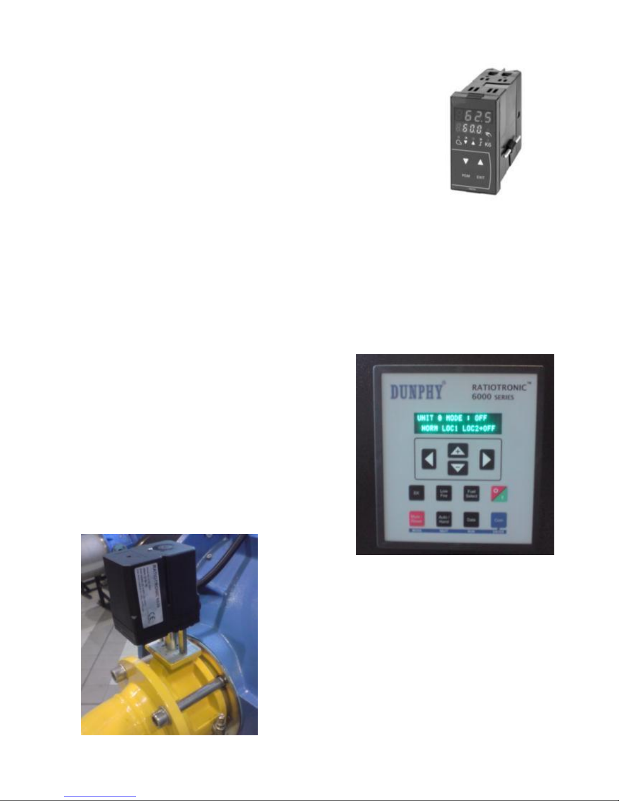
4.3 Electronic Modulation burners (M RT)
ME burners are fitted with electronic control systems
which have direct control over the air damper and gas
butterfly valve using high precision digital servo motors.
The Air / Gas or Air / Oil ratio is defined by a profile
curve which is programmed into the controller during the
commissioning phase.
Ratiotronic 6000 series controllers are generally fitted to
these burners however Siemens LMV2.. series and
LMV5.. series controllers may also be offered as an
alternative.
ME burners are relatively complex products and it is
recommend that they are commissioned by qualified
Dunphy personnel.
Documentation on these controllers is too lengthy to
incorporate into this document and therefore is supplied as
a separate manual. Both manuals must be used in
conjunction with each other when commissioning and
operating the burner.
Page 43
Operating Instructions For TD/TAD4 Dual Fuel Burner
June 13 43 of 165 TD/TAD4 Manual Rev 4
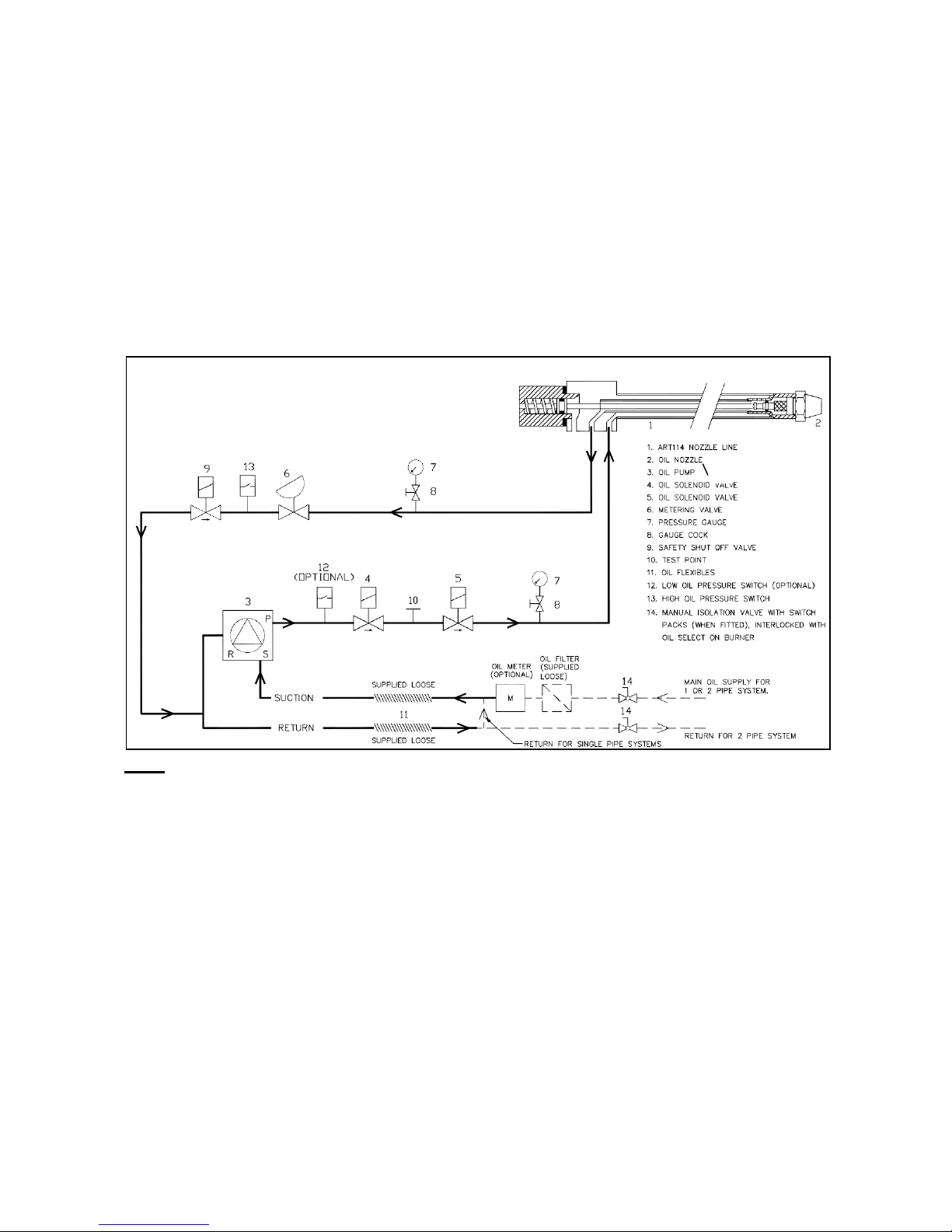
4.3.1 Oil Operating System Modulating Burners ART 114 and ART 1400 Nozzles
Atomisation of the oil is by means of a single nozzle which works on the spill-back principle. The
nozzle fits into a hydraulic nozzle line assembly that allows oil from the pump outlet to circulate
through the nozzle and back through the metering valve to the pump return when the burner is
ready to fire, N.C. solenoid valves 4 & 5 open allowing oil to flow through the nozzle. the return
path from the nozzle line flows through a metering valve and back to the return of the pump
through a safety shut off valve.
The oil volume is controlled by a metering valve 6, in the spill line restricting the amount of spilled
oil and therefore increasing the volume that passes through the nozzle for combustion.
Control of both the metering valve and the air shutter is achieved by means of independent servo
motors which are positioned by the electronic control system.
Key
1) Nozzle Line Assembly
2) Nozzle
3) Oil Pump (Dunphy)
4) Pump Discharge Valve - Normally Closed
5) Pump Discharge Valve - Normally Closed
6) Oil Metering Valve (Dunphy)
7) Pressure Gauge - 0-40 Bar
8) Gauge Clock
9) Non - Return Valve
10) Test Point
11) Flexible Oil Line (Supplied Loose)
12) Low Oil Pressure Switch (Optional)
13) High Oil Pressure Switch
14) Manual Isolation Valve with Switch Packs (when fitted), interlocked with oil select on
burner.
Page 44
Operating Instructions For TD/TAD4 Dual Fuel Burner
June 13 44 of 165 TD/TAD4 Manual Rev 4
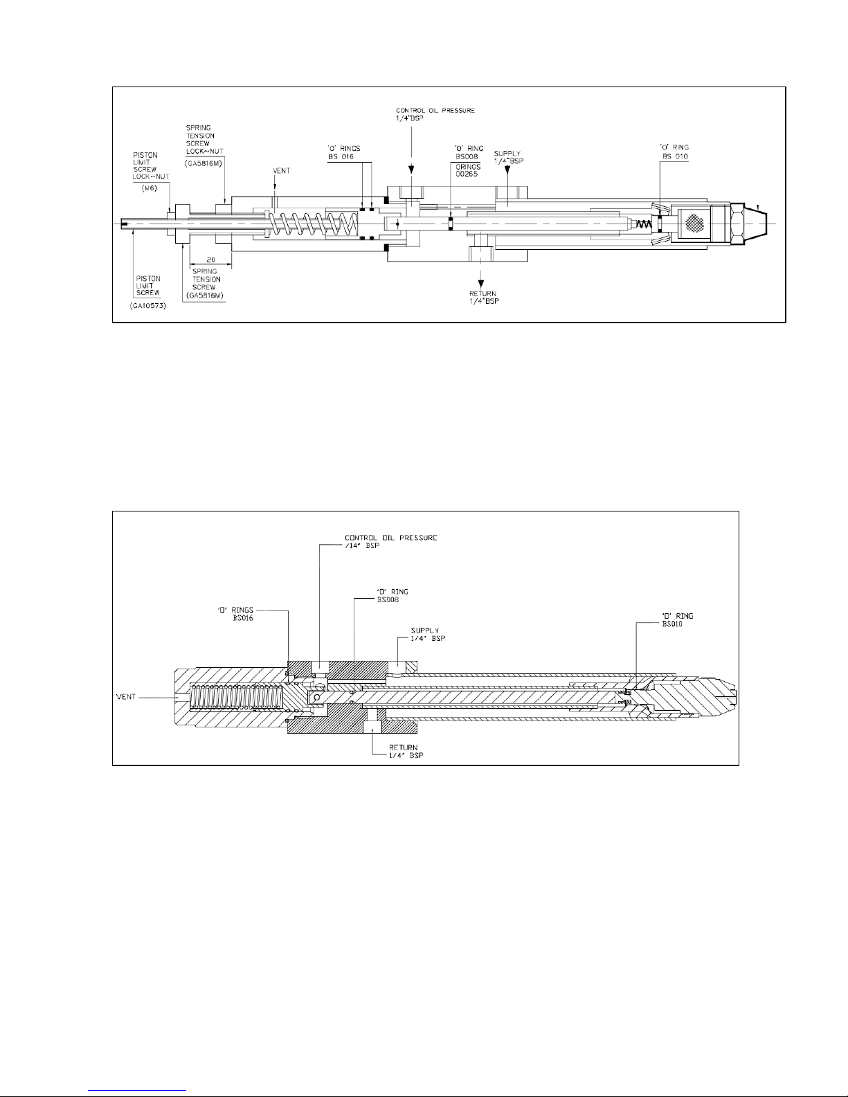
4.3.2 ART114 Burner Gun
To set the spring tension of the piston, the spring tension screw is set 20mm from the back chamber
as shown above. The piston stroke is setup using the piston limit screw. The screw is first fully
screwed in so that the piston cannot move; the screw is then moved out by 10mm to set the stroke.
The nozzle has a vent on the back chamber to allow the piston to move, DO NOT BLOCK THE
VENT.
4.3.3 ART 1400 Burner Gun
The ART1400 nozzle has a set spring tension and piston stroke; no adjustments can be made to the
operation of the burner gun.
The nozzle has a vent on the back chamber to allow the piston to move, DO NOT BLOCK THE
VENT.
Page 45

Operating Instructions For TD/TAD4 Dual Fuel Burner
June 13 45 of 165 TD/TAD4 Manual Rev 4
6 10 14 18 21 24 MAX
40 - 7 11 18 26 37 49 150 2.5
50 - 9 14 22 33 47 61 180 2.85
60 - 11 17 27 40 58 74 200 3. 15
70 16 22 30 43 56 72 86 210 3.2
80 18 24 34 48 64 83 98 230 3.2
90 20 27 37 54 72 94 110 254 3.2
100 22 30 42 60 80 105 122 270 3.2
112 24 33 46 67 90 118 137 290 3.2
125 27 36 52 76 103 135 153 320 3.3
140 31 42 59 86 117 152 172 380 3.35
160 35 48 67 98 132 175 196 430 3.5
180 40 54 76 112 150 195 220 460 3.6
200 44 60 86 126 170 220 245 550 4
225 48 67 96 143 192 250 276 600 4
275 58 80 118 175 240 310 337 700 4
300 62 88 130 195 270 350 368 750 4
330 67 96 145 220 300 395 405 800 4
360 73 106 160 240 335 - 440 870 4
400 79 117 180 266 375 - 490 900 4
450 89 133 198 296 420 - 557 960 4
500 98 148 220 333 467 - 612 1025 4
550 108 162 248 367 514 - 673 1100 4
625 124 184 281 417 584 - 765 1200 4
700 138 209 315 464 648 - 857 1300 4
ATOMIZER
NUMBER
RECOMMENDED
MAXIMUM
TURN-DOWN RATIO
PUMP
OUTPUT
RETURN PRESSURES IN BAR
OUTPUTS IN KILOGRAMS/hr
CAPACITY TABLES FOR
TYPE ART114/1400 RETURN FLOW NOZZLES
Supply pressure - 30 bar Viscosity - 5cSt (35 secs Redwood) Maximum output with return closed.
Page 46
Operating Instructions For TD/TAD4 Dual Fuel Burner
June 13 46 of 165 TD/TAD4 Manual Rev 4
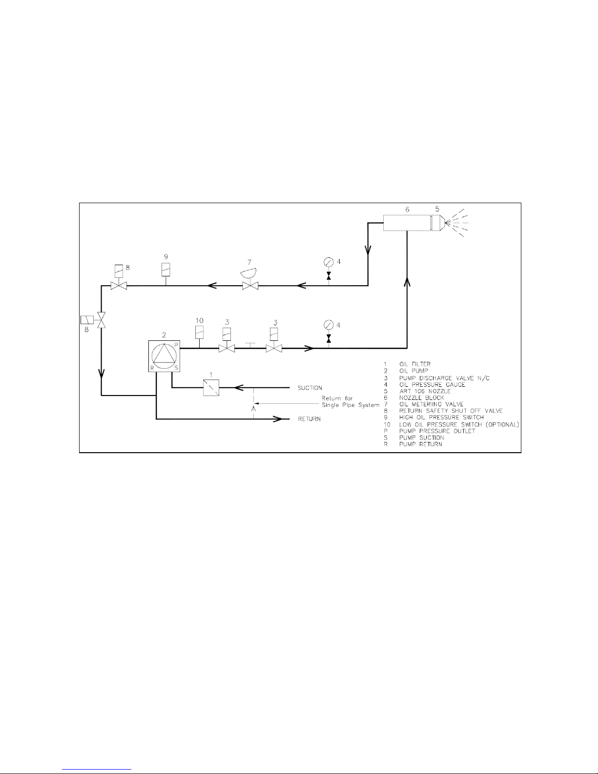
4.3.4 Oil Operating System Modulating Burners ART 106 Nozzle
Atomisation of the oil is by means of a single nozzle which works on the spill-back principle.
From the schematic diagram below it can be seen that when the oil supply is admitted to the
nozzle by the two main oil valves, the flow can either pass through the nozzle into the furnace or
can return down the spill line to the pump return.
The control of the oil volume is achieved by a metering valve in the spill line restricting the amount
of `spilled` oil and therefore increasing the volume that passes through the nozzle for combustion.
Control of both the metering valve and the air shutter is achieved by means of a modulating
motor which is positioned by potentiometer according to the control signal.
On burner shutdown both the main safety shut off valves and the return safety shut off valves
close simultaneously to isolate the nozzle and reduce any possibility of oil spillage into the furnace.
Page 47
Operating Instructions For TD/TAD4 Dual Fuel Burner
June 13 47 of 165 TD/TAD4 Manual Rev 4
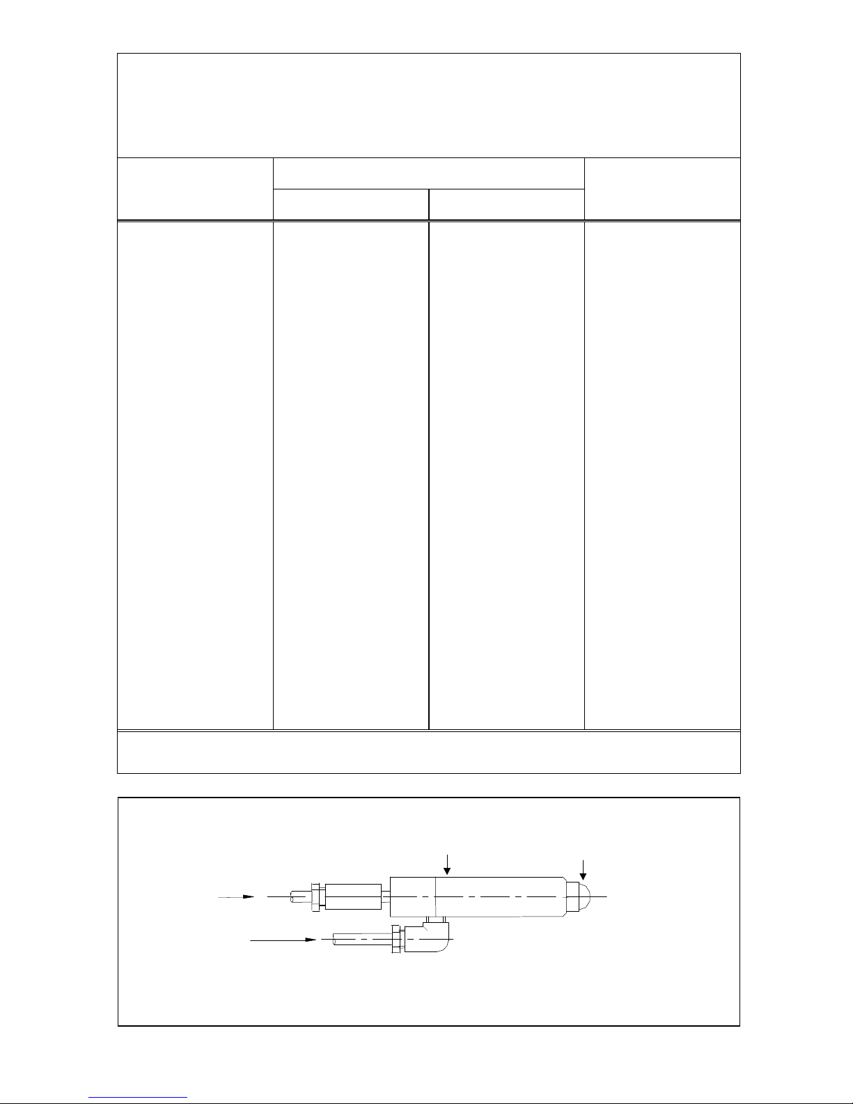
CAPACITY TABLES FOR
TYPE ART 106 RETURN FLOW NOZZLES
Supply pressure - 20 bar Viscosity - 5 cSt ( 35 secs Redwood )
NOZZLE
NOZZLE OUTPUT Kg/hr
TURN-DOWN
NUMBER
RETURN PRESSURE
@ 3 bar
CLOSED
RETURN
RATIO
1.25 1.9 5.3 2.8 1.5 2.15 6.4 3.0 1.75 2.6 7.5 2.9 2.0 3.05 8.5 2.8 2.25 3.4 9.6 2.8 2.5 3.8 10.8 2.8 2.75 4.1 11.0 2.7 3.0 4.2 13.0 3.1 3.25 4.75 14.0 2.9 3.5 5.0 15.0 3.0 4.0 5.7 17.0 3.0 4.5 6.5 19.5 3.0 5.0 7.3 22.0 3.0 5.5 7.7 24.0 3.1 6.0 8.5 26.0 3.1 6.5 9.0 28.0 3.1 7.0 9.8 30.0 3.1 7.5 10.2 32.5 3.2 8.0 11.0 35.0 3.2 8.5 11.5 37.0 3.2 9.0 12.2 39.5 3.2 10.0 13.5 44.0 3.3 11.0 15.2 48.0 3.2 12.0 17.0 53.0 3.2 14.0 18.7 62.0 3.3 16.0 21.5 71.0 3.3 18.0 23.8 80.0 3.4 20.0 26.5 88.0 3.3
Note:- Turn-down ratio will increase with supply pressures
OIL SUPPLY
OIL RETURN
ART 106
SPILL-BACK NOZZLE BLOCK
ART 106
SPILL-BACK OIL NOZZLE
ART 106 SPILL-BACK NOZZLE BLOCK AND NOZZLE
Page 48
Operating Instructions For TD/TAD4 Dual Fuel Burner
June 13 48 of 165 TD/TAD4 Manual Rev 4
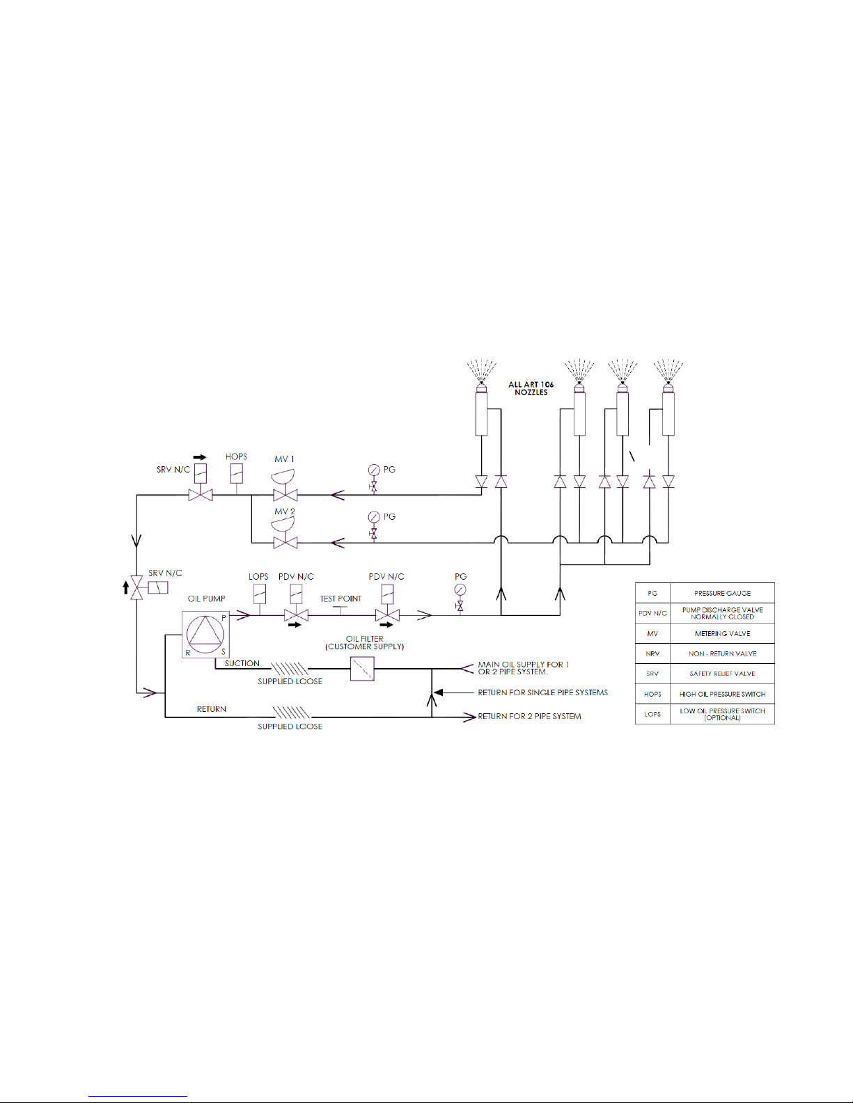
4.3.5 Oil Operating System Modulating Burners Multi-Oil Nozzles
Atomisation of the oil is by means of three nozzles which work on the spill-back principle. The
nozzle fits into the hydraulic nozzle line assemblies that allow oil from the pump outlet to circulate
through the nozzles and back through the metering valves to the pump return when the burner is
ready to fire, two PDV N/C solenoid valves open allowing oil to flow through the nozzles. The
return path from the centre nozzle flows through metering valve MV1, while the three outer nozzle
flows through MV2, they then join a common oil line, passing through two N/C safety shut off
valves, and back to the return of the pump.
The oil volume is controlled by the metering valves (MV1 and MV2) in the spill line restricting the
amount of spilled oil and therefore increasing the volume that passes through the nozzle for
combustion.
Control of both metering valves and the air shutter is achieved by means of independent servo
motors which are positioned by the electronic control system.
Page 49
Operating Instructions For TD/TAD4 Dual Fuel Burner
June 13 49 of 165 TD/TAD4 Manual Rev 4
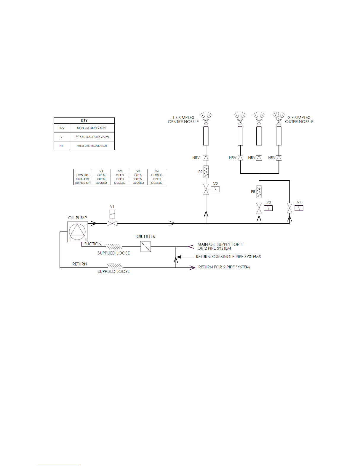
4.3.6 Oil Operating System High/Low Burners Multi-Oil Nozzles
Atomisation of the oil is by mean of three outer nozzles and one central nozzle. The pump pressure
is set at 25 Bar, the two pressure regulators controlling the pressure to all four nozzles are set at 10
Bar. On Low fire V1, V2 and V3 are open, V4 is closed. This allows oil to pass through all four
nozzles at a pressure of 10 Bar. On High fire, V1,V2, V3 and V4 are opened, oil at 10 Bar flows
through the centre nozzle, oil flows through the three outer nozzles at 25 Bar through V4 bypassing
the pressure regulator through V3.
Page 50

Operating Instructions For TD/TAD4 Dual Fuel Burner
June 13 50 of 165 TD/TAD4 Manual Rev 4
4.3.7 Oil Operating System Air / Steam Atomising
The ‘TA’ principle of operation is that oil, carrying both heat and hydraulic energy, enters a mixing
chamber in the nozzle where it is mixed with the streams of the atomising fluid (compressed air or
steam), carrying kinetic energy and in the case of steam, heat energy.
The combination of forces resulting from the directional differences between the oil flow, steam
flow and the kinetic and heat energy forces cause an emulsification process to take place.
The oil/steam or oil/air mixture then impinges on the nozzle pintle plate which gives secondary
atomisation, and finally passes out of the nozzle orifice which imparts a swirling motion into the
finely atomised spray. The emerging angle of the spray can vary according to the type of nozzle
fitted.
The oil supply from the pump passes through the pump discharge valve, the pre-heater the metering
valve and the nozzle line and goes back to the pump return via the V1 main oil valve and a nonreturn valve. When the burner is switched on, the oil pre-heater (When fitted) is energised and the
oil temperature is raised to the required level. When the oil reaches the required temperature the
burner motor/pump is started and the oil is allowed to circulate through the burner pipework until
the correct temperature is attained throughout the system.
The check stat then sends a signal to the control box which starts the firing cycle by opening the air
damper to the high fire position. When the control box reaches the firing stage, the air damper
drives to low fire position and the ignition spark is switched on.
Both V1 normally open and V1N normally closed nozzle line solenoids are energised together
releasing oil through the nozzle, and the atomising medium solenoid (PV) opens to allow air or
steam into the nozzle mixing chamber.
The resulting mixture is ignited by the spark from the ignition electrode or by a pilot gas ignition
system.
The main oil pressure is set, by means of the pump pressure regulating screw and the atomising oil
pressure adjusted at the metering valve to give the correct low and high fire oil throughputs. The
atomising medium pressure must be adjusted at the pressure regulator (RG) in conjunction with the
oil pressure to ensure smooth light up and optimum combustion throughout the firing range.
The air shutter is adjusted to give optimum combustion efficiency throughout the firing range.
Page 51
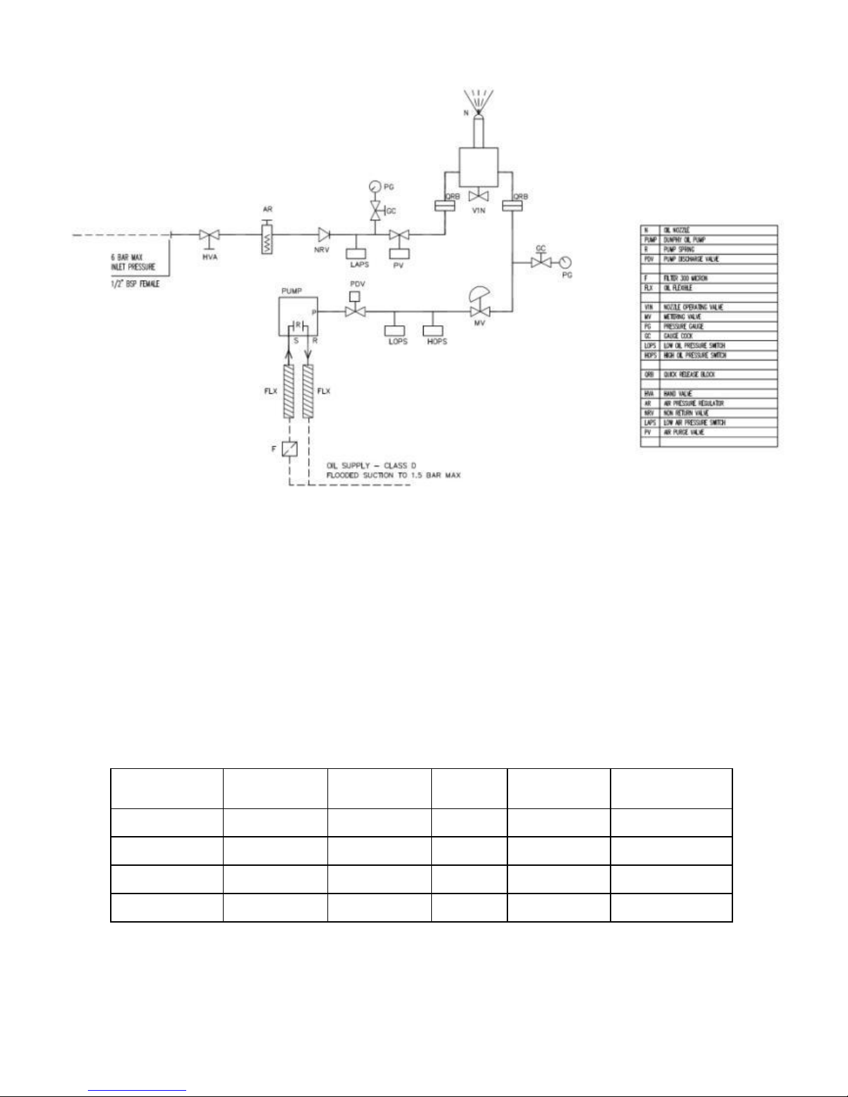
Operating Instructions For TD/TAD4 Dual Fuel Burner
June 13 51 of 165 TD/TAD4 Manual Rev 4
4.3.8 Fuel Pumps and Motors
All `TD` series burners are supplied with a separate, directly coupled fuel pump and drive motor.
Details of the various sizes of pumps and motors are given in the table below.
BURNER TYPE
PUMP TYPE
MOTOR SIZE
(kW)
RPM
DRIVE
COUPLING
OIL LINE
CONNECTIONS
TD410ZHL
DH1-1-30
1.1 2800
Fig 71
3
/4" BSP
TD410ZM
DH1-1-30
1.1 or 2.2
2800
Fig 71
3
/4" BSP
TD415YM
DH1-2-30
2.2 2800
Fig 71
3
/4" BSP
TD420YM
DH2-1-30
3.0 2800
Fig 71
1" BSP
Page 52
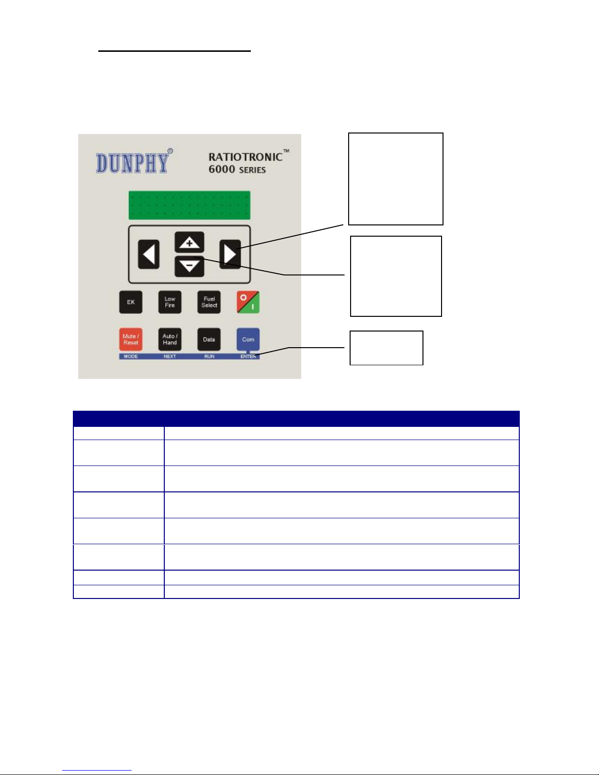
Operating Instructions For TD/TAD4 Dual Fuel Burner
June 13 52 of 165 TD/TAD4 Manual Rev 4
5 Operation & User Interface
5.1 The Display / Keypad
The display is a 2 line, 20 characters per line, dot matrix vacuum fluorescent type allowing the use
of plain text messages for display parameters. The keypad is a membrane construction with tactile
keys to give a positive feedback of the actuation.
Key
Function
EK
Selects Engineers Key mode.
LOW FIRE
Pressing this key will force the burner to Low fire until the key is pressed
again to release the burner to modulate.
FUEL SELECT
Changes Fuel/Profile. If the fuel is changed when the burner is firing, the
burner will go off then restart firing the new fuel selection.
BURNER O-I
Sets the burner On or Off and enables changes between normal and local
operation. Note: Terminal PE9 must be ON for this switch to start the burner.
MUTE / RESET
Press this key to mute (open) the alarm relays, and then hold the key down
for approximately three seconds to reset the cleared faults.
AUTO / HAND
Selects auto or manual burner modulation. In manual mode the UP/DOWN
keys are used to alter the fire rate.
DATA
Selects different data types on the display window.
COM
Changes operation to commission mode via a pass-code.
The UP/DOWN keys are
used to adjust the fire rate in
manual modulation mode.
In commission mode, they
are used for data value
selection.
The SCROLL keys are used to
view boiler and burner status
data during normal running
conditions.
In commission mode, these
keys select option parameters,
which are adjusted by the
UP/DOWN keys.
Alternate key functions
when in commission
mode.
Page 53

Operating Instructions For TD/TAD4 Dual Fuel Burner
June 13 53 of 165 TD/TAD4 Manual Rev 4
5.2 Start -up Sequence
When a fuel selection is made and the ‘burner select’ signal is given to start up the burner, the
controller performs the sequence described below. If a gas profile is selected and the safety valve
proving function is selected, the controller will perform safety valve pressure proving concurrently
with the start-up sequence.
State
no.
State name
Description
0. Non-volatile
lockout
All fuel valve outputs are OFF and the Alarm output is ON until
muted. The burner is held in this state until all faults are
removed.
1. Burner off
The burner is checked to make sure that it has switched off
completely. Testing includes - main fuel safety valves closed, no
flame signal and no air pressure’ signal. The controller will
remain in this state until there is a call for heat from the PID
system.
2.
Wait for purge
The controller waits for both a burner select (PE9 ON) and a
fuel/air profile to be selected. Progression to stage 3 or 5 maybe
held off by external influences, e.g. Digital Communications
control or digital input controlled by an external circuit.
3.
Open fuel valve
If gas firing and safety valve proving are selected, the gas valve
servo motor is moved ‘open’ for five seconds to allow any gas
in the test section to be vented easily during the proving
sequence.
4.
Hold fuel valve
The fuel motor is held in position until step 1 of the safety valve
proving sequence (open main valve 2, or vent valve) is
completed.
5.
Prove closed
positions
If gas is selected, the gas valve proving sequence begins. The
fuel and air motors are moved to closed position until they stop.
The final positions are compared with the closed positions
stored in memory when the profile is commissioned.
6.
Prove air
pressure
The burner motor output is set ON and air pressure prove time
(t1) is initiated. The selected motors are moved ‘open’ towards
the purge position. If the ‘fan start early’ option parameter has
been set then the motors will not move until the option time has
expired.
7.
Prove purge
positions
When the air pressure prove time has elapsed, the air pressure
switch must give a ‘pressure’ signal or the controller will
lockout the burner and move to stage 0. If primary air is
selected, then both primary and secondary air pressure signals
must be ON to prove air pressure. The selected motors are
driven ‘open’ until they reach their commissioned purge
position.
Page 54

Operating Instructions For TD/TAD4 Dual Fuel Burner
June 13 54 of 165 TD/TAD4 Manual Rev 4
State
no.
State name
Description
8.
Pre-purge
Once the servo motors are at their purge positions the controller
starts the pre-purge (t2) timer.
9.
Move to ignition
positions
When t2 has elapsed, the fuel and the air motors are moved to
the ignition position for the selected profile. The controller will
wait at the ignition positions while the gas valve proving
sequence finishes before progressing to stage 10
10.
Pre-ignition
Once the fuel and air motors are at their ignition positions, the
ignition transformer output is energized and pre-ignition time
(t3) is starts.
11.
Pilot ignition
Once t3 has elapsed the ignition transformer remains on, first
main valve if required for pilot flame gas, and pilot valve
outputs are energised and the first safety time (t4) is started.
If firing on oil and ignition selected to be with both pilot and
main valve, use timing in the start-up sequence table for main
valve 1.
If firing on oil and ignition with main valve is not selected the
pilot ignition will occur with only the pilot valve, use timing in
the start-up sequence table for main valve 2.
12.
Pilot ignition
interval
When t4 is complete, a flame must be detected or the controller
will lockout the burner and move to stage 0. The ignition
transformer may optionally be on or off (See option parameter
14.6).
13. Main ignition
Once the pilot interval time (t5) has elapsed, the second (and
first if not already open) main valve output(s) for gas, or main
oil valve output for oil is energized and the second safety time
(t6) is started.
If firing on oil and ignition with main valve was selected the
main oil valve will have already opened for pilot ignition. The
ignition transformer may optionally be on or off (See option
parameter 14.6). A flame and air pressure signal must be
detected or the controller will lockout the burner and move to
stage 0.
14.
Wait for Main
flame established
When t6 has expired, the pilot valve output is turned off. If
permanent pilot is selected and the burner is firing on gas, then
the pilot will remain open with the main valves.
Main flame interval time (t7) is started. A flame and air pressure
signal must be detected or the controller will lockout the burner
and move to stage 0.
15.
Moving to low
fire
When t7 has elapsed, the flame is considered established and the
fuel and air motors are moved from their ignition positions to
their low fire positions and held at those positions for the
duration of the Low Fire Hold Time (t8). A flame and air
pressure signal must be detected or the controller will lockout
the burner and move to stage 0.
Page 55

Operating Instructions For TD/TAD4 Dual Fuel Burner
June 13 55 of 165 TD/TAD4 Manual Rev 4
State
no.
State name
Description
16.
Modulation
When t8 has elapsed the fuel and air motors are modulated
according to the demand placed on the burner. If the fuel
selection is changed or the ‘burner on’ signal (PE9) is removed,
the main valve output(s) are turned off. A flame and air
pressure signal must be detected or the controller will lockout
the burner and move to stage 0.
17.
Move to postpurge
If Post Purge is not selected then the controller returns to state 1
to wait for another start-up.
If Post Purge has been selected then the fuel servo motor is
moved to its closed position, and the selected air motor(s) are
moved to their post purge position(s).
18.
Post-purge
When the air drive(s) have reached their post purge positions
then the Post Purge Time (t9) is started. When t9 has elapsed,
the burner motor is turned off and the controller returns to state
1 to wait for another start-up.
5.3 Modulation
During stage 16 (modulation), the controller will position the fuel and air motors within the
programmed profile appropriate to the requirement for heat. The controller has 2 modes of
operation using the standard RATIOTRONIC modulation function, Normal and Local. The mode
of operation is set via the keypad by pushing the “Burner ON/OFF” key and selecting the mode.
Using the programmable block function (option) within the controller it is possible for the
modulation control to be generated with customised options, these are not covered in the standard
manual.
5.4 Normal mode
In Normal mode, the modulation rate is determined by the internal PID control settings, Manual
modulation from the keypad, or by one of the following remote influences:
Auxiliary modulation input,
Digital set point selection
Serial communications – Comview or Lead/Lag.
5.5 Local mode
In Local mode, the modulation rate is determined by either the internal PID settings or Manual
modulation via the UP/DOWN keys. External modulation inputs and set point selection inputs are
ignored.
When “Local1” is displayed the burner is running using the Set point 1 PID settings.
When “Local2” is displayed the burner is running using the Set point 2 PID settings.
5.6 Non-volatile lockout
Non-Volatile lockouts cannot be cleared without operator intervention and are remembered in the
event of power being removed from the controller.
A non-volatile lockout will occur under the following conditions:
Page 56

Operating Instructions For TD/TAD4 Dual Fuel Burner
June 13 56 of 165 TD/TAD4 Manual Rev 4
If any step of the gas proving sequence fails
In stages 1-9 (inclusive) if a flame is detected
In stages 11-16 (inclusive) if a flame is not detected
In stage 4 if the air pressure switch goes high (air pressure present)
In stages 7-18 (inclusive) if the air pressure switch goes low (air pressure not present)
In stages 5, 7 and 8, stages 10-16 (inclusive) and stage 18 if a motor is not in the correct
position
In any stage, if an internal or external fault not previously mentioned occurs which may
affect the safe operation of the burner
5.7 Ratiotronic 6000 Inverter interface additional information
The Ratiotronic 6000 may have an optional daughter board within the main enclosure to allow
control of 1 or 2 inverter drives (daughter board dependent). Optionally the daughter board is also
available to allow feedback to be taken from directly from encoders measuring the speed of the
relevant motor, fan or pump shaft. There is also an option to allow the speed of an additional rotary
device to be monitored as an encoder input.
When not configured to control an inverter, the 4-20mA outputs may be configured to transmit
system variables as current outputs.
There are special wiring requirements for inverter feedback.
5.8 Post Purge Operation
If a post combustion purge is selected (with option parameter 7.9), a normal shutdown post purge
will be performed at low fire. The drives will move to the low fire position (if not already there)
and the post-purge time will then start. If the burner has turned off because the fuel profile selection
has been removed (i.e. set to NONE), no post-purge will be performed.
If the burner locks out at or after ignition, and a post-purge time has been entered, the controller
will also attempt a post purge. For a flame failure fault, the controller will attempt to post purge at
high fire. For all other faults, the drives will stay at the positions they were in when the lockout
occurred. In both cases, the post-purge time starts at the moment the lockout occurs – the controller
does not wait for drives to position before starting the post-purge time.
Page 57
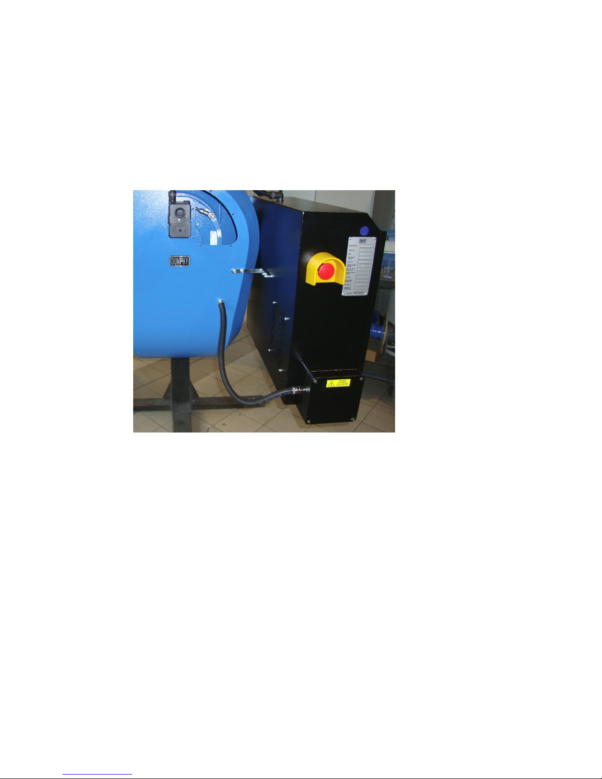
Operating Instructions For TD/TAD4 Dual Fuel Burner
June 13 57 of 165 TD/TAD4 Manual Rev 4
5.9 Emergency Stop
The emergency stop or e-stop is a safety mechanism used to shut off the burner in an emergency
situation in which it cannot be shut down in the usual manner. Unlike a normal shut-down
switch/procedure, which shuts down the burner in an orderly fashion and turns it off without
damaging it, an e-stop is designed and configured to a) completely abort the operation at all costs
and b) be operable in a manner that is quick, simple (so that even a panicking user with
impaired executive function can operate it), and, usually, c) be obvious even to an untrained
operator or a bystander. The e-stop features a removable barrier to provide protection against
accidental activation.
Page 58

Operating Instructions For TD/TAD4 Dual Fuel Burner
June 13 58 of 165 TD/TAD4 Manual Rev 4
6 Component Setup Parameters
Before the commissioning process of the burner can take place, there are certain components like
the Ratiotronic 6000, inverter (when fitted), etc, which will need to be setup. The burner should be
factory set; however, if the parameters have been erased for whatever reason, then this section can
be used as a starting point. Please note that a fuel / air profile will not have been setup. Please also
note that this parameter set should be used in conjunction with the manual.
6.1 Ratiotronic 6000
Option
Value
Description
Comments
0.1
xxx
Site passcode
last 3 digits of burner serial number
0.2
0
Serial communications control address
0.3
0
Reset hours run
0.5
0
Language Select
0.7
1
IsoComsAddress
0.8
2
IsoComsSetting
1.0
5
Power up option
5=ignore alarms for 5 seconds at
power up
1.1
1
Keyboard auto/manual enable
1.2
0
Fault mute input enable
1.3
0
External profile select enable
1.4
0
Gas valve proof of closure select
1.5
0
Oil valve proof of closure
1.6
0
Second airflow switch (primary air) enable
1.7
0
Safety time configuration set
1.8
0
Force Mode Input
2.0
0
Drive 0 name
not used
2.1
2
Drive 1 name
gas servo motor
2.2
3
Drive 2 name
oil servo motor
2.3
10
Drive 3 name
air servo motor
2.4
11
Drive 4 name
VSD drive
2.5
0
Drive 5 name
2.6
0
Drive 6 name
2.7
0
Drive 7 name
2.8
0
Drive 8 name
2.9
0
Drive 9 name
3.0
0
Drive 0 serial number
not used
3.1
xxxx
Drive 1 serial number - Gas Servo
1st 4 Digits of Ser No
3.2
xxxx
Drive 2 serial number - Oil Servo
1st 4 Digits of Ser No
3.3
xxxx
Drive 3 serial number - Air Servo
1st 4 Digits of Ser No
Found on side of servo motor
3.4
VSD1
Drive 4 serial number
3.5
0
Drive 5 serial number
3.6
0
Drive 6 serial number
3.7
0
Drive 7 serial number
3.8
0
Drive 8 serial number
3.9
0
Drive 9 serial number
4.0
0
Drive 0 profile assignment
not used
4.1
1
Drive 1 profile assignment
profile 1
4.2
2
Drive 2 profile assignment
profile 2
4.3
3
Drive 3 profile assignment
profiles 1 + 2 = 3
4.4
3
Drive 4 profile assignment
profiles 1 + 2 = 3
Page 59

Operating Instructions For TD/TAD4 Dual Fuel Burner
June 13 59 of 165 TD/TAD4 Manual Rev 4
4.5
0
Drive 5 profile assignment
4.6
0
Drive 6 profile assignment
4.7
0
Drive 7 profile assignment
4.8
0
Drive 8 profile assignment
4.9
0
Drive 9 profile assignment
5.0
0
Drive 0 rotation
0 = anti-clockwise / 1 = clockwise
5.1
0
Drive 1 rotation
0 = anti-clockwise / 1 = clockwise
5.2
0
Drive 2 rotation
0 = anti-clockwise / 1 = clockwise
5.3
0
Drive 3 rotation
0 = anti-clockwise / 1 = clockwise
5.4
0
Drive 4 rotation
0 = anti-clockwise / 1 = clockwise
5.5
0
Drive 5 rotation
0 = anti-clockwise / 1 = clockwise
5.6
0
Drive 6 rotation
0 = anti-clockwise / 1 = clockwise
5.7
0
Drive 7 rotation
0 = anti-clockwise / 1 = clockwise
5.8
0
Drive 8 rotation
0 = anti-clockwise / 1 = clockwise
5.9
0
Drive 9 rotation
0 = anti-clockwise / 1 = clockwise
6.1
1
Fuel train for profile 1
gas
6.2
1
Fuel train for profile 2
oil
6.3
0
Fuel train for profile 3
6.4
0
Fuel train for profile 4
7.0
0
Fan on early time
7.1
15
Air Proving time
7.2
30
Pre-purge time
Do not reduce this timing
7.3
1
Pre-ignition time
Do not extend this timing
7.4
3
Pilot ignition time
Do not extend this timing
7.5
3
Pilot hold time
Do not extend this timing
7.6
3
Main ignition time
Do not extend this timing
7.7
3
Ignition hold time
Do not extend this timing
7.8
5
Low fire hold time
Do not extend this timing
7.9
30
Post purge time
Do not reduce this timing
8.0
0
Ignition spark output check
8.1
1
Flame failure response time
8.2
0
Extend false flame response time
9.0
0
Inverter control accuracy
0 = low / 1 = high
9.1
1
Inverter error tolerance
0 = low / 1 = high
9.2
100
Inverter closed loop gain
9.3
30
Inverter stop time
9.4
30
Inverter acceleration time
9.5
0
VSD1 speed encoder scaler
9.6
0
VSD2 speed encoder scaler
9.7
0
Low speed cup limit
9.8
0
Oil warning speed
10.0
0
Gas pressure sensor select
1 – valve proving via sensor,
0 – valve proving via pressure
switches
10.1
0
Gas pressure sensor span
10.2
70
Gas pressure nominal
Parameters 10.2, 10.5 and 10.6 will
give a valve proving time of approx
40secs. This is an optimised set of
figures – do not alter
10.3
0
Gas pressure low limit
10.4
0
Gas pressure high limit
10.5
1
Test volume
Page 60

Operating Instructions For TD/TAD4 Dual Fuel Burner
June 13 60 of 165 TD/TAD4 Manual Rev 4
10.6
7.5
Maximum permissible leakage rate
10.7
0
Vent valve select
10.8
1
Valve proving select
1 – VPS enabled, DO NOT DISABLE
10.9
3
VPS Power Time
12.0
0
Photocell / IR flame detection select
12.1
0
Pilot flame threshold photocell
12.2
0
Main flame threshold photocell
12.3
0
Centre frequency photocell
12.4
0
Frequency pass ban photocell
13.0
x
UV/Ionisation flame detection
1=non-shuttered/2=shuttered
13.1
x
Pilot flame threshold
non-shuttered = 20, shuttered = 10
13.2
20
Main flame threshold
14.0
6
Primary fault relay
14.1
0
Limit relay
14.2
0
Oxygen + fuel temperature limit relay
14.3
0
Permanent gas pilot select
14.4
1
Pilot with/without main valve select
0 = without / 1 = with
14.5
1
Direct ignition on oil
14.6
0
Spark termination
14.7
1
Oil pump relay function
1 = light oil / 2 = heavy oil
14.8
0
Extended oil pilot
15.0
2
Modulation input sensor type
2 = 4-20mA
15.1
x
Modulation input decimal places
0 = temp / 1 = pressure
15.2
0
Modulation input zero value
15.3
xx
Modulation input span value
default: temp = 150, pressure = 16.0
15.4
x
Set-point display units
1 = bar / 3 = deg c
15.5
0
Boiler high safety limit
15.6
20
Modulation time
15.7
0
Bumpless transfer
15.8
1
Low fire before off
0 = no / 1 = yes
16.1
0
Go back to pilot
16.2
0
Allow profile swap online
16.3
011
HV input 12 alarm/lockout function
Boiler high limit stat, on PE7
16.4
012
HV input 13 alarm/lockout function
Fan trip, on PE8
16.5
xx
HV input 12 display message
11 – high temp, 13 – high pressure,
on PE7
16.6
17
HV input 13 display message
Fan interlock, on PE8
17.1
0
Relay 1 output function
(display unit) PR1,PR2,PR3
17.2
20
Relay 2 output function
(display unit) PR5,PR6,PR7
17.3
19
Relay 3 output function
(display unit) PR7,PR8,PR9
17.4
20
Relay 4 output function
(controller) PD6,PD7,PD8
17.5
19
Relay 5 output function
(controller) PD4,PD5,PD6
17.6
0
Relay 6 output function
(controller) PD1,PD2,PD3
17.7
26
Relay 7 output function
(26 = VSD1 start circuit) PZ17-PZ18
17.8
0
Relay 8 output function
PZ15-PZ16
18.1
0
LV input 1 function
PB9-PB10
18.2
0
LV input 2 function
PB9-PB11
18.3
0
LV input 3 function
PB9-PB12
18.4
0
LV input 4 function
PB9-PB13
18.5
22
LV input 5 function
Low Gas Pressure PB14-PB15
18.6
21
LV input 6 function
High Gas Pressure PB14-PB16
Page 61

Operating Instructions For TD/TAD4 Dual Fuel Burner
June 13 61 of 165 TD/TAD4 Manual Rev 4
18.7
0
LV input 7 function
PB14-PB17
18.8
0
LV input 8 function
PB5-PB6
18.9
0
LV input 9 function
PB5-PB7
19.1
0
LV input 1 message
PB9-PB10
19.2
0
LV input 2 message
PB9-PB11
19.3
0
LV input 3 message
PB9-PB12
19.4
0
LV input 4 message
PB9-PB13
19.5
5
LV input 5 message
Low Gas PB14-PB15
19.6
4
LV input 6 message
High Gas PB14-PB16
19.7
0
LV input 7 message
PB14-PB17
19.8
0
LV input 8 message
PB5-PB6
19.9
0
LV input 9 message
PB5-PB7
20.0
0
Set-point select input
1-7 or 12-13
20.1
0
Boiler shutdown input
1-7 or 12-13
20.2
0
Low fire hold input
1-7 or 12-13
20.3
0
Oxygen trim disable input
1-7 or 12-13
20.4
0
Ignition wait input
1-7 or 12-13
20.5
0
Purge hold input
1-7 or 12-13
20.6
0
Purge time start input
1-7 or 12-13
20.7
0
Analogue input 5 option
aux mod input
20.8
0
Lead boiler select
1-7 or 12-13
21.0
0
Set-point 1 enable
21.1
x
Set-point 1 control value
default: temp = 80, pressure = 8.0
21.2
0.5
Set-point 1 proportional value
default: temp = 1, pressure = 0.5
21.3
1
Set-point 1 integral time
21.4
0
Set-point 1 derivative time
21.5
2
Set-point 1 control limit type
Deviation
21.6
0.5
Set-point 1 low limit control value
default: temp = 10, pressure = 0.5
Burner On 0.5 below SP
21.7
0.5
Set-point 1 high limit control value
default: temp = 10, pressure = 0.5
Burner Off 0.5 above SP
21.8
0
Remote set-point 1 zero (4mA) value
21.9
0
Remote set-point 1 span (20mA) value
22.0
0
Set-point 2 enable
22.1
0
Set-point 2 control value
22.2
0
Set-point 2 proportional value
22.3
0
Set-point 2 integral time
22.4
0
Set-point 2 derivative time
22.5
0
Set-point 2 control limit type
22.6
0
Set-point 2 low limit control value
22.7
0
Set-point 2 high limit control value
22.8
0
Mod Max Enable Input
22.9
0
Mod Max Value
23.0
0
Warming enable
23.1
0
Warming limit
23.2
0
Warming time
24.0
0
Number of sequence lag boilers
enables into sequencing
24.1
0
1st lag boiler address
24.2
0
2nd lag boiler address
24.3
0
3rd lag boiler address
24.5
0
Lead assign type
24.6
0
Lag on rate
Page 62

Operating Instructions For TD/TAD4 Dual Fuel Burner
June 13 62 of 165 TD/TAD4 Manual Rev 4
24.7
0
Lag on delay
24.8
0
Lag off rate
24.9
0
Lag off delay
29.0
0
Analogue output 1 function
VSD1 overrides if selected
29.1
0
Analogue output 1 zero (4mA) value
29.2
0
Analogue output 1 span (20mA) value
29.3
0
Analogue output 2 function
VSD2 overrides if selected
29.4
0
Analogue output 2 zero (4mA) value
29.5
0
Analogue output 2 span (20mA) value
29.6
0
Analogue output 3 function
29.7
0
Analogue output 3 zero (4mA) value
29.8
0
Analogue output 3 span (20mA) value
30.0
0
Oxygen probe interface serial number
30.1
0
Oxygen probe calibration offset value
30.2
0
Oxygen probe calibration gain value
30.3
0
Oxygen probe calibration gas
concentration
30.4
0
Flue & inlet temp sensor units
30.5
0
Oxygen input function
30.6
0
Oxygen probe calibrate enable
30.7
0
Boiler transport delay
30.8
0
Reset oxygen trim profile
30.9
0
Automatic trim commissioning
31.0
0
Limit modulation range
31.1-
31.4
0
Trim type for profiles
32.0
0
Trim limit default
32.1-
32.4
0
Trim limits
33.1-
33.4
0
Trim integral gain
34.0
0
Trim proportional gain default
34.1-
34.4
0
Trim proportional gain
35.0
0
Inlet temp sensor serial number
35.1-
35.4
0
Hydrocarbon ratios for each fuel
respectively
35.5-
35.8
0
Calorific values of fuels / profiles 1-4
respectively
35.9
0
Boiler radiated heat loss
36.0
0
Flue temperature alarm select
36.1-
36.4
0
Flue temperature low alarm value
37.1-
37.4
0
Flue temperature high alarm value
38.0
0
Oxygen alarm select
38.1-
38.4
0
Oxygen low alarm value at low fire
39.1-
39.4
0
Oxygen low alarm value at high fire
40.1-
40.4
0
Oxygen high alarm at low fire
41.1-
41.3
0
Oxygen high alarm at high fire
42.0
0
Second oxygen probe select
Page 63

Operating Instructions For TD/TAD4 Dual Fuel Burner
June 13 63 of 165 TD/TAD4 Manual Rev 4
42.1
0
Second oxygen probe calibration offset
42.2
0
Second oxygen probe calibration gain
42.4
0
Maximum oxygen variation
42.5
0
Maximum flue temp variation
42.6
0
Second oxygen probe calibration enable
44.0
0
Set real time clock
44.1
0
Set year
44.2
0
Set month
44.3
0
Set day of month
44.4
0
Set day of week
44.5
0
Set hours
44.6
0
Set minutes
44.7
0
Set seconds
44.9
0
Clear fault history
45.0
0
Erase/Restore enable
45.1
0
Erase command
45.2
0
Restore command
Page 64

Operating Instructions For TD/TAD4 Dual Fuel Burner
June 13 64 of 165 TD/TAD4 Manual Rev 4
6.2 Danfoss VLT FC 102
PNU
NAME
FACTORY DEFAULT
DCL SETTING
0-20
DISPLAY LINE 1.1
REF %
ANALOG INPUT 53
0-21
DISPLAY LINE 1.2
MOTOR AMPS
0-22
DISPLAY LINE 1.2
POWER KW
0-23
DISPLAY LINE 2
FREQUENCY HZ
0-24
DISPLAY LINE 3
KW/H COUNTER
SPEED RPM
0-40
LCP HAND START
ENABLE
DISABLE
0-41
LCP STOP
ENABLE
DISABLE
0-42
LCP AUTO START
ENABLE
DISABLE
0-43
LCP RESET
ENABLE
1-00
CONFIG MODE
OPEN LOOP
1-03
VT CHARACTER
AEO FUNCTION
1-20
MOTOR POWER
xxxKW
Use Motor Dataplate Info
1-22
MOTOR VOLTAGE
400 V
1-23
MOTOR FREQUENCY
50 HZ
1-24
MOTOR CURRENT
xxx A
Use Motor Dataplate Info
1-25
MOTOR NOM SPEED
xxxx RPM
Use Motor Dataplate Info
1-29
AUTO MOTOR ADAPT
NO AMA
ENABLE COMPLETE
1-90
MOTOR THERM PROTECTION
ETR TRIP 1
THERMISTOR TRIP
1-93
THERMISTOR SOURCE
NONE
ANALOG INPUT 54
3-02
MIN REFERENCE
0.0 HZ
20.0 HZ
3-03
MAX REFERENCE
50.0 HZ
3-13
REFERENCE SITE
HAND / AUTO
REMOTE
3-15
REFERENCE 1 SOURCE
ANALOG INPUT 53
3-41
RAMP UP TIME
45.0 SEC
15 SEC
3-42
RAMP DOWN TIME
90.0 SEC
20 SEC
PNU
NAME
FACTORY DEFAULT
DCL DEFAULT
4-10
MOTOR SPEED DIRECTION
BOTH DIRECTIONS
CLOCKWISE
4-12
MOTOR SPEED LOW LIMIT
0.0 HZ
20.0 HZ
4-14
MOTOR SPEED HIGH LIMIT
50.0 HZ
4-16
TORQUE LIMIT MOTOR MODE
110 %
150 %
4-18
CURRENT LIMIT
110 %
150 %
4-19
MAX OUTPUT FREQUENCY
100 HZ
4-50
WARNING LOW CURRENT
0.0 A
4-51
WARNING HIGH CURRENT
99.0 A
4-52
WARNING LOW SPEED
0.0 RPM
4-53
WARNING HIGH SPEED
3000 RPM
5-01
TERMINAL 27 MODE
INPUT
5-10
TERMINAL 18 DIGITAL INPUT
START
5-11
TERMINAL 19 DIGITAL INPUT
NO OPERATION
5-12
TERMINAL 27 DIGITAL INPUT
COAST INVERSE
5-13
TERMINAL 29 DIGITAL INPUT
JOG
NO OPERATION
5-14
TERMINAL 32 DIGITAL INPUT
NO OPERATION
5-15
TERMINAL 33 DIGITAL INPUT
NO OPERATION
5-40
RELAY 1 FUNCTION
ALARM
RUNNING
5-41
RELAY 1 ON DELAY
0.01 SEC
Page 65

Operating Instructions For TD/TAD4 Dual Fuel Burner
June 13 65 of 165 TD/TAD4 Manual Rev 4
5-42
RELAY 1 OFF DELAY
0.01 SEC
5-40
RELAY 2 FUNCTION
RUNNING
ALARM
5-41
RELAY 2 ON DELAY
0.01 SEC
5-42
RELAY 2 OFF DELAY
0.01 SEC
6-12
TERMINAL 53 MIN SCALING
4.00 mA
6-13
TERMINAL 53 MAX SCALING
20.00 mA
6.14
TERMINAL 53 LOW
REF/FEEDBACK VALUE
0.00
20.00
6.15
TERMINAL 53 HIGH
REF/FEEDBACK VALUE
50.00
6-20
TERMINAL 54 MIN SCALING
0.07 V
6-21
TERMINAL 54 MAX SCALING
10.0 V
6-50
TERMINAL 42 ANALOG OUT
SPEED – 0 HIGH LIMIT
SPEED 4-20mA
6.51
TERMINAL 42 MIN SCALING
0 %
40 %
6.52
TERMINAL 42 MAX SCALING
100 %
100 %
8.30
PROTOCOL
FC
MODBUS RTU
8.31
ADDRESS
1
2
8.32
BAUD RATE
19200 BAUD
9600 BAUD
8.33
PARITY/STOP BITS
EVEN PARITY/1 STOP BIT
NO PARITY/1 STOP
BIT
Page 66

Operating Instructions For TD/TAD4 Dual Fuel Burner
June 13 66 of 165 TD/TAD4 Manual Rev 4
6.2.1 RWF 40.000A97 Default Burner Settings
SETTING
FACTORY
DEFAULT
DCL SETTING
REMARKS
C111
9030
F000
0000
PRESSURE
TEMP
C112
0010
0000
C113
0110
0110
SCL
0.0
0.0
SCH
100.0
16.0
100
PRESSURE
TEMP
SCL2
0.0
0.0
SCH2
100.0
100.0
SPL
0.0
0.0
SPH
100
16.0
100.0
PRESSURE
TEMP
OFF1
0.0
0.0
OFF2
0.0
0.0
OFF3
0.0
0.0
DF1
1.0
1.0
DF3
1278
1278
OLLO
-199.9
-199.9
OLH1
999.9
999.9
DTT
30
30
AL
0.0
0.0
HYST
1.0
1.0
PB.1
10.0
1.0
10.0
PRESSURE
TEMP
DT
80.0
25.0
RT
350
100.0
DB
1.0
1.0
TT
15.0
15.0
HYS.1
-5.0
-1.0
-5.0
PRESSURE
TEMP
HYS.2
3.0
0.5
3.0
PRESSURE
TEMP
HYS.3
5.0
1.0
5.0
PRESSURE
TEMP
Q
0.0
0.0
H
1.0
1.0
P
0.0
0.0
SP1
60.0
8.0
80.0
PRESSURE
TEMP
User definable
Page 67

Operating Instructions For TD/TAD4 Dual Fuel Burner
June 13 67 of 165 TD/TAD4 Manual Rev 4
7 Commissioning
7.1 Basic settings
It is essential that heat output of the appliance is known in order that the correct fuel input can be
calculated and set. If there is any doubt at all with regard to the appliance rating, the manufacturer
should be consulted before the burner is fired. The calorific value of the fuel must be known and
measurement of the fuel input should be by meter wherever possible.
Do not leave the burner firing at a rate which is known to be or which may be excessive, this will
result in damage to the appliance.
The nett flue gas temperature should be taken throughout the process of setting combustion. The
figure will vary according to the construction of the appliance but will normally be in the range
of 180° to 250°C gross. – if in doubt what this figure should be, please consult the boiler/appliance
manufacturer.
Calculation of burner firing rate ( output ).
Qf
Qn
k
kW[ ]
Qf = Burner Firing Rate ( Output ) kW
Qn = Boiler nominal thermal output ( kW )
k = Boiler Efficiency
Calculation of Gas Throughput at Nominal Boiler Output
Vb
Qn
HU k
m h
*
[ ]
3
Vb = Gas Throughput ( Fuel Input ) m3h.
Qn = Boiler nominal thermal output ( kW )
k = Boiler Efficiency
HU = Calorific Value of Fuel under Normal Conditions ( kWh/m3 )
Calculation of Gas Throughput for Boiler Firing Rate
Vb
Qf
HU
m h [ ]
3
Vb = Gas Throughput ( Fuel Input ) m3h.
Qf = Burner Firing Rate ( Output ) kW
HU = Calorific Value of Fuel under Normal Conditions ( kWh/m3 )
Burner output ( kW ) =
Boiler output ( kW )
Boiler efficiency
The indicating scale on the air damper motor is calibrated so that zero represents the fully closed
position for the air damper. The indicated low fire and high fire positions will be the result of the
Page 68
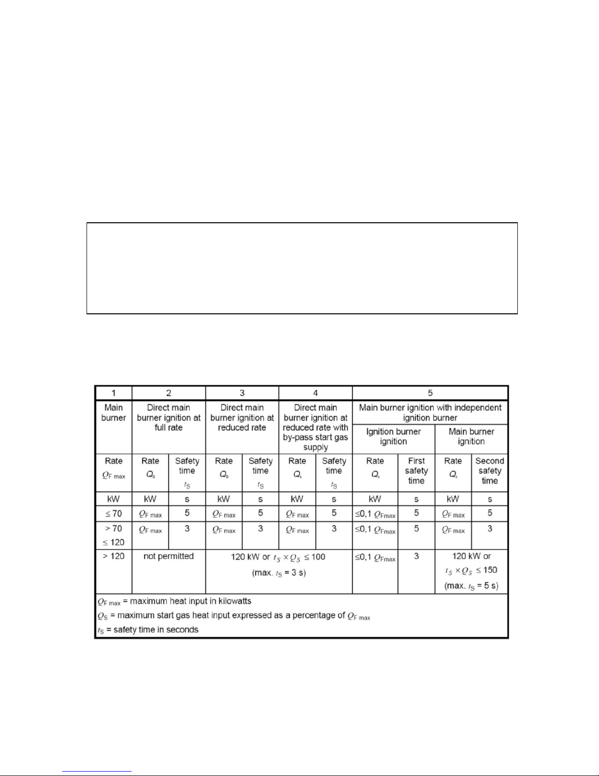
Operating Instructions For TD/TAD4 Dual Fuel Burner
June 13 68 of 165 TD/TAD4 Manual Rev 4
NOTE:
ON ANY BURNER, AN ALMOST INFINITE COMBINATION OF COMBUSTION
HEAD COMPONENTS AND SETTINGS MAY BE USED TO ACHIEVE OPTIMUM
EFFICIENCY AND A FLAME SHAPE TO SUIT A VERY WIDE RANGE OF HEAT-
RAISING APPLIANCES. THE MOST SUITABLE COMBINATION/SETTINGS
MUST BE DETERMINED DURING THE COMMISSIONING PROCEDURE.
adjustments described below, there are no pre-determined positions applicable to a particular
burner. The scale reading only represents the air damper opening and not the firing rate!
Adjustments to the burner combustion head (for example the position of the flame ring in the nose
cone) may be necessary during the `setting up` of a burner.
Details of the settings for a particular burner , firing a given make of boiler, cannot be given in a
manual of a realistic size, however, standard basic settings are given in section 3 of this manual.
The size and relative position of the flame ring to the cone will have an appreciable effect on the
volume and velocity of air passing over the flame ring and this must be taken into consideration
when setting the combustion efficiency, with adjustments made as necessary. Adjustment of the
flame plate in relation to the nose cone can be made by loosening the screws holding the nose cone
in place and moving the nose cone backwards or forwards. After adjustments have been made,
ensure that screws are retightened and sealed in place.
7.2 Start Gas Heat Input
The table below summarises the ignition gas rates for different burner configurations.
The start gas heat input must not exceed 120kW or the value given by the equation :
ts x Qs ≤ 100
where:
Page 69

Operating Instructions For TD/TAD4 Dual Fuel Burner
June 13 69 of 165 TD/TAD4 Manual Rev 4
ts is the safety time in seconds (s):
Q
s
is the maximum start gas heat input expressed as a percentage of the main gas rate
This approximates to an ignition rate of less than one third of the maximum firing rate.
If the burner is fitted with a separate pilot, the start gas heat input of the ignition burner must not
exceed the value given by the equation:
ts x Qs ≤ 150
where:
ts is the safety time in seconds (s):
Q
s
is the maximum start gas heat input expressed as a percentage of the main gas rate
7.3 Pre-commissioning
Note: The following tests must be carried out before commissioning is started.
Check that the appliance has been filled to the correct level
Check that the appliance isolating valves are fully open.
Where fitted, check that the flue damper is locked in the open position.
Check that the flue-draught stabiliser moves freely
Check that the gas supply is guaranteed and is at the correct pressure.
Check that the gas meter is the correct size.
Ensure that a manual gas isolation valve is positioned as close as possible to the burner and
that all gas pipe work is adequately supported.
Check that the external electrical connections are in accordance with the appliance
manufacturers wiring instructions.
Make certain that both fuel supplies and electrical supplies have been isolated.
Ensure that all gas, oil and electrical connections are tight as connections may come loose
during transportation.
Check the electrode gap to be 3mm at the narrowest point of the ignition electrode (twin)
and the tip of gas ignition electrode is 3mm away from the gas nozzle outlet.
Set the firing rate control switch to `low fire` to ensure that the burner will remain at low
fire after light-up.
Hot water boilers - check operation of the control and limit thermostats and that the boiler
has been filled with water.
Steam boilers - confirm the operation of the boiler feed pump and switch, and check that
the water level controls are working.
After the initial firing of the boiler, do not leave the unit operating in an unmanned boiler
house unless the boiler on/off control has been operated and set at a suitable figure and the
flame failure system on the burner has been checked.
Page 70

Operating Instructions For TD/TAD4 Dual Fuel Burner
June 13 70 of 165 TD/TAD4 Manual Rev 4
7.4 Commissioning – High Low and Pneumatic Modulation burners - Firing on Gas
7.4.1 Dry run
Note: Gas leak checks must be carried out using a suitable non-corrosive leak detection fluid.
Check for gas leaks on meters, governors and all mains gas supply pipe work.
Ensure all pipework leading up to the burner main gas valve has been purged according to
IGE/UP/1 Soundness testing and Purging of Industrial & Commercial Gas Installations
Ensure that the burner manual isolation valve is closed.
Check that all isolation valves in the main gas supply pipe work are open.
Remove or loosen the gas inlet pressure test point on the inlet side of the gas valve and open
the burner isolation valve until all air has been purged between the isolation valve and the
burner gas valve.
When this has been done, close the isolation valve.
Note: For the following tests a digital manometer will be required.
7.4.2 Check for leaks through the automatic gas valve.
Connect the manometer to the gas inlet test point on the automatic gas valve, open the manual gas
isolation valve for two seconds and then close it again.
The pressure shown on the manometer should remain constant.
7.4.3 Check rotation of burner fan motor
Switch on mains electrical supply. Momentarily 'blip' the burner fan connector and check rotation
of fan against direction of rotation sticker fixed to the rear of the burner. If motor rotates in the
wrong direction, changeover two of the incoming 3 phase supply. Repeat test to ensure rotation is
now correct.
7.4.4 Check for correct control sequence.
Open manual gas isolation valve for two seconds and then close it again, sealing the gas
between the automatic gas valve and the isolation valve.
Check that all time switches, room thermostats etc are in the `on` position and that the boiler
thermostat is set to the required temperature.
Switch on the mains electrical supply.
Select 'Gas' on the control system
The control box will commence the starting sequence which, depending on the control box,
will average:-
Prepurge time 30 seconds
Pre-ignition time 3 seconds
Pilot proving time 3 seconds
When the pilot proving time is reached, the automatic gas valve is energised and will
release the gas trapped between the valve and the closed isolation valve.
The burner will then stop because the pressure acting upon the gas pressure proving switch
will be reduced due to the isolation valve being closed.
Switch off the electrical supply on completion of this test.
Page 71

Operating Instructions For TD/TAD4 Dual Fuel Burner
June 13 71 of 165 TD/TAD4 Manual Rev 4
7.4.5 Firing the burner
Ensure that the heat demand will allow an extended run, otherwise the burner may not
continue to fire throughout the time required for throughput measurement or commissioning
procedure.
Unscrew or loosen the outlet gas pressure test point on the gas valve and connect a
manometer.
Open the manual gas isolation valve.
Switch on the mains electrical supply and, if the control box is locked out (indicated by the
reset button being illuminated) press the lockout reset button. For electrical modulation
systems, please consult relevant manual.
Provided all control devices, thermostats etc are in the `on` position the burner control box
will start the operating sequence. For information relating to sequence of operation please
refer to section 5.
If the control sequence fails to start, check for correct setting of the gas pressure proving
switch.
The amount of gas flowing through the valve can be adjusted by using the ‘ ’ and
‘ ’ and is proportional to the amount of combustion air set by the air damper
motor. Cam setting for the air damper have been described in section 4.1.
‘ ’ is used to set the Low Fire rate and ‘ ’ is used to adjust the high fire
rate. A combination of the two settings will define an operating line between high fire and
low fire and the valve will maintain the air/gas ratio across this range. Full information on
the gas multiblock may be found in section 4.
Adjustment of ‘ ’ will have an effect on the setting of ‘ ’ and vice-
versa. It may take 3 or 4 fine adjustments at both high fire and low fire to ensure good
combustion at both ends.
ALWAYS CHECK THE COMBUSTION READINGS AFTER MAKING ADJUSTMENTS.
7.4.6 Combustion values and results
All combustion readings must be taken with an approved and correctly calibrated test kit.
The following combustion values should be reached:-
Low Fire
CO content 0 - 20 ppm
CO2 content 9 - 11 %
O2 content 5.4 - 2%
High Fire
CO content 0 - 20 ppm
CO2 content 10 - 11%
O2 content 3.6 - 2%
In all cases the CO figure should not exceed 100mg/m3 maximum.
The nett flue gas exit temperatures should be taken throughout the process of setting the
combustion.
The figures will vary according to the type of appliance but for shell and sectional boilers will be in
the range of 180 - 250C gross.
Always keep the exhaust flue gas temperatures within the manufacturers recommended
range and ensure that the appliance is not over or under fired. Warm up the boiler, or raise
steam in accordance with appliance manufacturer’s instructions.
Page 72

Operating Instructions For TD/TAD4 Dual Fuel Burner
June 13 72 of 165 TD/TAD4 Manual Rev 4
7.4.7 Adjustment of Gas Proving Pressure Switch
Loosen the screw in the gas inlet measuring point, connect a manometer and remove the clear
plastic cover from the gas pressure detector.
Switch on the burner and allow to fire.
Close the burner manual gas isolation valve slowly until the gas pressure is reduced to 50%.
Adjust the numbered black plastic ring on the gas pressure detector until the burner switches off.
Switch off the mains electrical supply to the burner, remove the manometer and seal the test point
screw.
Open the manual gas isolation valve and switch on the burner.
7.5 Oil Firing
All burners using oil as a fuel are fired before despatch as part of the standard test programme. This
does not mean that the pump pressure or any other adjustment applying to the oil system is
necessarily correct for the application.
Commissioning of the burner must include confirming that the nozzle size and characteristics are
suitable, calculating the fuel pressure required to give boiler M.C.R. and ensuring that, subject to
the requirements given below, the firing rate is correctly set.
The following text in included on the basis that the burner has been commissioned on gas and that
the boiler or appliance controls have been set.
The change - over of fuels is made by operation of the selector switch on the burner control cabinet.
This selector switch controls two contactors which electrically isolate one fuel from the other. On
electronic modulating burners, fuel selection can be made via the keypad.
For change-over to either fuel the switch selection is made through the 'off' position which causes
the burner control box to extinguish the flame before recycling.
The starting cycle will not immediately commence because it will be necessary for the burner
motor to slow down, reducing the air flow to a level which allows the air pressure switch to return
to the 'no' air position.
Note: Even on oil firing the leak detection cycle will be activated.
Before changing to oil firing, ensure that the oil pump has been properly vented and flooded.
No mechanical changes or re-adjustment of components are required for the burner to be changed
from one fuel to another.
Before the first firing on oil, it is always advisable for the availability of fuel, fire valves open etc,
to be confirmed.
Check that the burner will remain at low fire.
7.5.1 Setting the Firing Rate, High / Low Oil Burners
Step 1
Set the Low Fire air damper motor setting to between 1 and 2 on the scale and the high fire
air damper setting to between 5 and 6 on the scale. Set O2 to approx 3 on the scale.
Ensure that the High / Low switch is in the low fire position and switch on the burner.
Momentarily 'blip' the oil pump contactor to check for correct rotation of pump - ensure it
rotates according to rotation sticker fixed to rear of the motor. If rotation is incorrect, swap
Page 73

Operating Instructions For TD/TAD4 Dual Fuel Burner
June 13 73 of 165 TD/TAD4 Manual Rev 4
over two pluses on the pump motor. Do not swap the mains electrical feed as this will also
reverse the burner fan motor rotation.
Start the burner and allow to go through pre-purge cycle. When the burner reaches its
ignition position, the ignition transformer is switched on, followed by the fuel pump motor,
and then the two solenoid valves, which should result in the burner lighting.
Set the pump pressure to approx 25 bar.
Adjust the low fire air position to give the following figures:
Carbon Dioxide: 11 - 14%
Smoke Number: 0 - 1 (
Excess Oxygen: 3 - 6%
Nett Flue Gas Temperature: 180 - 220ºc
Step 2
Allow burner to move to High Fire position. On its way to High Fire, the V2 Oil Valve will
energise, thus passing oil into the second nozzle.
Once at High Fire, adjust air damper to give combustion figures similar to above.
Switch between Low and high Fire, checking the firing rate and combustion, ensuring that
consistent figures and smooth, reliable light-up are being obtained.
Listen for signs of flame instability.
With the burner firing, remove and cover the photocell, ensuring that the burner goes
immediately to lockout.
Warm up the boiler or raise steam slowly, and in accordance with the manufacturer's
instructions.
After running for a reasonable amount of time, remove the combustion head and check for
any oil impingement, oil leaks, or fouling at the flame plate.
If necessary, make adjustments to the combustion head to cure this.
Check the flame ring for indications of overheating or impingement by the oil spray.
The basic, relative positions of the combustion head components are given in section 3 of this
manual, but the principles to be followed are that:-
1. The ignition electrodes must be positioned so that the spark, which `strikes` at the narrowest
point is blown forward by the combustion airflow on to the widest point of the `horns`. This
will ensure that the arcing takes place within the cone of atomised fuel, with a consequent
immediate ignition of the fuel.
Note that if the electrodes are set too far forward, they will be subjected to continuous
impingement by un-burnt fuel, some of which will carbonise, quickly reducing the intensity
of the spark and leading to poor ignition.
2. The relative position of the flame ring must give a flame which is `anchored` on to the front
face of the ring. The slotted vanes must be opened enough to allow the passage of an
adequate amount of air, which because of the swirl effect imparted, will be a major
stabilising factor. If the vane gap is irregular, the flame shape will be affected and soot will
build up at the points which restrict the air flow.
If the nozzle is too near to the flame ring, the flame will tend to `lift off`, giving very
unreliable ignition and a degree of instability which will make reliable operation, especially
when modulating from high to low fire.
3. The combustion head as an assembly, must be central in the draught tube, otherwise the air
velocity round the outside of the flame ring ( and therefore of the flame ) will vary in
Page 74

Operating Instructions For TD/TAD4 Dual Fuel Burner
June 13 74 of 165 TD/TAD4 Manual Rev 4
relation to the gap through which the air is passing, causing poor flame shape and
impingement on the furnace structure.
4. Where divergent ( expanded ) nose cones are used, the cone itself should be positioned
relative to the flame ring and allow an adequate volume of air for combustion, but at the
same time, give a velocity which is high enough to assist in shaping the flame to give
optimum combustion.
While the design of the combustion head is the major factor in obtaining maximum
combustion efficiency, careful setting of the various component parts is also important.
When a burner has been in service for a period long enough for its performance to be
confirmed and before the settings have been disturbed, the relative dimensions of the
combustion head components should be recorded, so that after dismantling for maintenance,
correct reassembly can be assured.
Set the high/low thermostat or pressure switch to a lower figure than the on/off control. The
difference should take account of demand, bringing the burner back to low fire early enough
to slow down any boiler pressure or temperature rise if the heat demand is less than the
boiler M.C.R. and reduce the on/off cycling of the burner. Equally the burner must revert to
its high fire rate in time to maintain the pressure or temperature above a figure which is
determined by site conditions.
Page 75
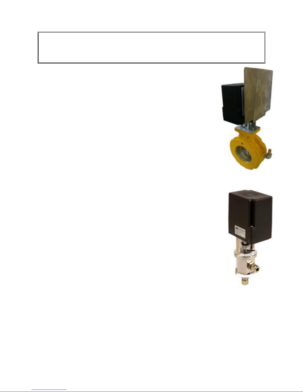
Operating Instructions For TD/TAD4 Dual Fuel Burner
June 13 75 of 165 TD/TAD4 Manual Rev 4
7.6 Electronic Modulating Burners
7.6.1 Gas Butterfly Valve
Control of the gas supply to the burner is performed using a butterfly valve.
material specification of blade and spindle can be altered depending on gas
type, E.G. Stainless Steel can be specified for Bio-gas.
Check the butterfly valve has been correctly set to zero - Please consult
manual for details. More details on the butterfly valve can be found in the
component section.
7.6.2 Oil Metering Valve
The oil metering valve is used to control the amount of oil returning from the
spill back oil nozzle line. On spill back systems, the witness mark on the
inner spool piece must be set to 'B'.
Set the pointer to zero - Please consult manual for details. With the pointer set to zero, this
represents maximum flow through the metering valve. As the valve modulates up to 90º, the valve
closes off, also closing off the return spill line from the oil nozzle line and
therefore increasing the firing rate. More details on the oil metering valve can be
found in the component section.
7.6.3 Adjustment of air pressure proving switch
Check the air pressure proving switch and, if necessary, set to 50% of
differential pressure.
Example of adjustment:-
Negative pressure ( – ) measured 4 mbar
Positive pressure ( + ) measured 5 mbar
Differential pressure is - 9 mbar
Switch off point of pressure switch is 4.5mbar
From this point all commissioning procedures are dictated by the Ratiotronic 6000 manual.
ALWAYS CHECK THE COMBUSTION READINGS AFTER MAKING ADJUSTMENTS
IMPORTANT!
When commissioning burners fitted with Electronic Modulating Control Systems, the
respective operating manuals must be followed. Only competent and trained personnel are
permitted to commission burners fitted with these controls.
Page 76

Operating Instructions For TD/TAD4 Dual Fuel Burner
June 13 76 of 165 TD/TAD4 Manual Rev 4
7.6.4 Ratiotronic programming
The Ratiotronic 6000 burner control system is generally pre-programmed in the factory prior to
despatch. However it is important that the parameters are checked against the lists supplied with the
test data supplied with the burner.
The combustion engineer must be competent with such a controller and be fully trained in burner
commissioning before proceeding any further.
This manual must be used in conjunction with the Ratiotronic 6000 manual at all times.
7.6.5 Setting the servo motors
Please refer to section 5 of the Ratiotronic manual.
In general the drive servo motors are allocated as follows:
Drive 1: Gas Butterfly valve
Drive 2: Oil Metering Valve
Drive 3: Air damper servo motor
Drive 4: Inverter
7.6.6 Burner Commissioning
All burners using oil as a fuel are fired before despatch as part of the standard test programme. This
does not mean that the pump pressure or any other adjustment applying to the oil system is
necessarily correct for the application.
Please now refer to ‘Section 6.6 Commission Ratio Mode’ of the Ratiotronic 6000 manual for
details on how to commission the burner.
7.6.7 Combustion values and results
All combustion readings must be taken with an approved and correctly calibrated test kit.
The following combustion values should be reached:-
Low Fire
CO content 0 - 20 ppm
CO2 content 9 - 11 %
O2 content 5 - 2%
High Fire
CO content 0 - 20 ppm
CO2 content 10 - 11%
O2 content 3.6 - 2%
In all cases the CO figure should not exceed 100mg/m3 maximum.
The nett flue gas exit temperatures should be taken throughout the process of setting the
combustion.
The figures will vary according to the type of appliance but for shell and sectional boilers will be in
the range of 180 - 250C gross.
Always keep the exhaust flue gas temperatures within the manufacturers recommended
range and ensure that the appliance is not over or under fired. Warm up the boiler, or raise
steam in accordance with appliance manufacturer’s instructions.
Page 77
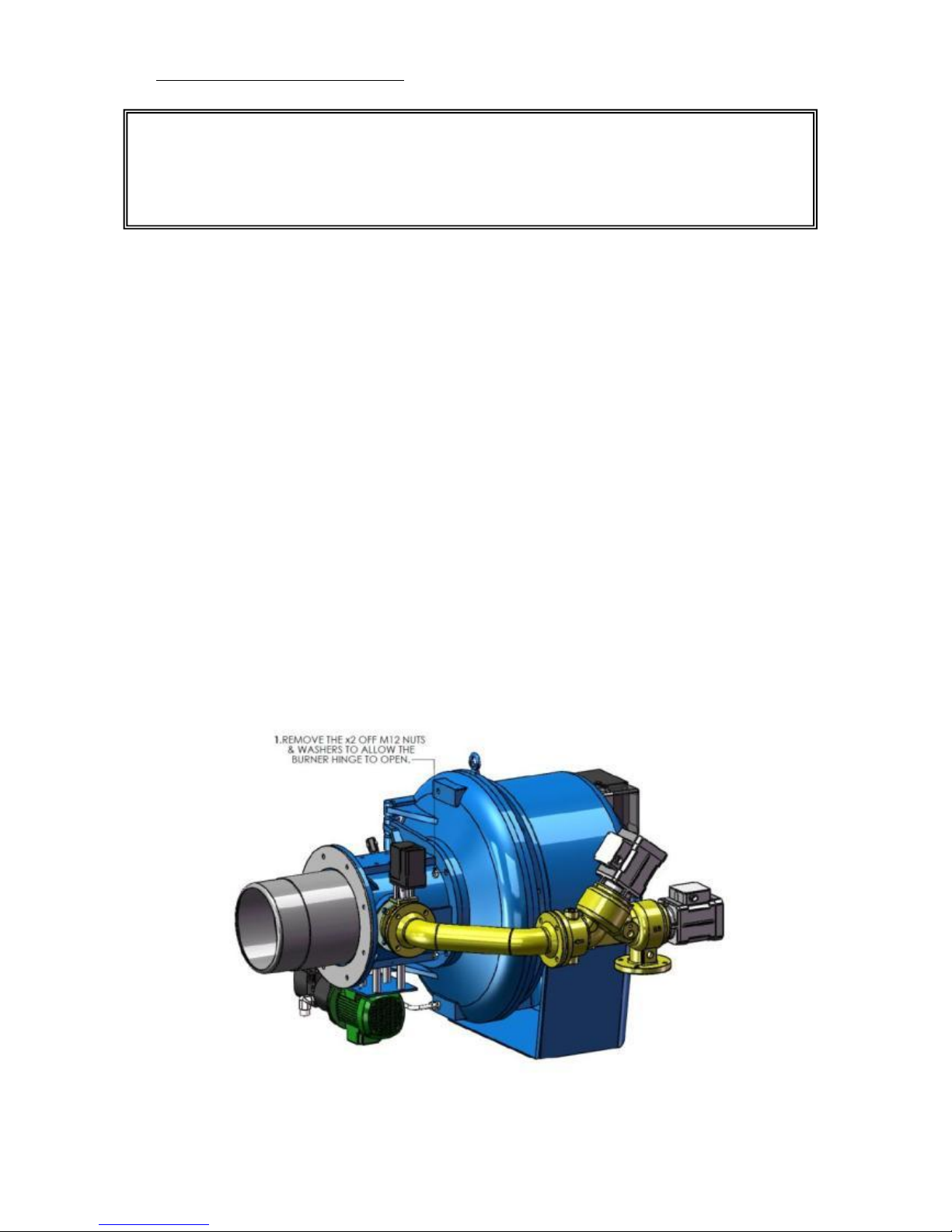
Operating Instructions For TD/TAD4 Dual Fuel Burner
June 13 77 of 165 TD/TAD4 Manual Rev 4
8 Burner Maintenance Schedule
The following schedules are only to be taken as a guide to those persons responsible for day to day
maintenance of the burners. Details of a service agreement covering the major items of routine
servicing are available on request.
An annual check by factory trained technicians is strongly advised.
All control circuit components, fire valves and other safety devices should have a functional check
at not greater than annual intervals.
Maintenance and inspection of boilers or other appliances must meet the requirements of the
manufacturers' schedules and of the insurers. It is usually more convenient to carry out burner
maintenance after the completion of the boiler inspection or cleaning, so that the burner can be fired
and the combustion reset to optimum figures.
The measurements given in the various combustion head drawings in this manual are to be regarded
as datum figures only. During commissioning, alterations may be made to the relative positions, or
to the components themselves, to suit the particular application.
Therefore, before dismantling the combustion head, take note of the measurements concerned and
record them on the manual's drawings. It is important that where possible components of the same
type and size are fitted as replacements.
The commissioning certificate for the burner should be available, to be used as a reference for the
fuel input and combustion figures which will give boiler MCR and the highest efficiency level.
8.1 Opening the Burner
To open the burner, the two nuts securing the hinge section to the fan section must be removed. The
burner will swing open on its hinge offering full access to all combustion head components.
When necessary checks/repairs have been carried out, close up in reverse order ensuring that the
locking nuts are fully tightened.
REMEMBER!
ELECTRICAL AND FUEL SUPPLIES MUST BE ISOLATED BEFORE ANY
MAINTENANCE WORK IS CARRIED OUT ON THE BURNER.
Page 78

Operating Instructions For TD/TAD4 Dual Fuel Burner
June 13 78 of 165 TD/TAD4 Manual Rev 4
8.2 Minor Maintenance
(a) Check the operation of the flame failure system daily by deliberately locking out the burner.
This can be achieved by either removing the UV cell, or on burners fitted with ionisation
probes isolating the gas supply to the burner.
(b) Where fitted, check and regularly clean the UV cell window with a soft cloth.
(c) Inspect the burner control cabinet to ensure that all indicator lamps are serviceable.
(d) Make a general check for cleanliness and security.
(e) As convenient, make an inspection of the combustion head components for cleanliness,
security and serviceability.
(f) Check the main gas valves for external hydraulic fluid leaks.
(g) Confirm the security of all linkages, locking nuts and any component parts fitted to the
burner
(h) Where a micro-ammeter is fitted make regular checks to confirm that the UV cell output
does not significantly deteriorate.
8.3 Major Maintenance
Take adequate safety precautions against the small amount of gas which escapes when gas train
components are removed.
Carry out all of the maintenance tasks listed above, plus the following:
(a) Remove the upstream pilot valve and determine the amount of dust etc. which is present. If
a substantial quantity is found, remove the upstream main gas valves from the burner and
clean the seats (Unibloc only, see 'Unibloc' section of this manual for actuator removal).
The Siemens valve is a sealed unit – any unauthorised opening will invalidate warranty.
(b) Check and clean any gas filters in the site pipework if significant quantities of dust or scale
are found. Make a request to the gas region for similar work on the service filter which
protects the meter
(c) Confirm correct operation of electrical components, e.g. control boxes, motor starters etc
and check tighten all electrical terminals.
(d) The nominal life of a U/V cell is 10,000 hours, subject to regular checks of the cell output
as registered on the micro-ammeter (which might indicate an earlier deterioration) the cell
should be changed every third year.
(e) Disconnect the air shutter linkage at the shutter spigot. Move the shutter by hand to confirm
freedom of movement. Clean as necessary (the PTFE bearing surfaces need no lubrication
but will require replacement when worn)
(f) Inspect the refractory of the burner mounting plate. Make good any defects in refractory or
sealing
(g) Ensure that boiler furnace sight glasses are clean and that their sealing is flue gas-tight.
(h) When the inspection and any rectification work has been completed on the burner/boiler,
bring the unit up to working temperature (slowly).
(i) With the boiler on line, confirm that the fuel throughput and combustion efficiency are
equal to the 'commissioned' figures.
Page 79
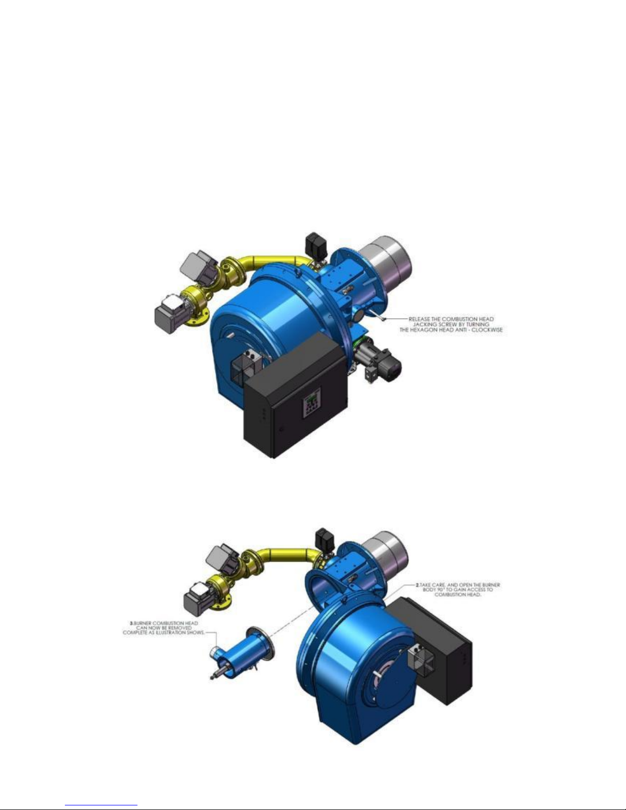
Operating Instructions For TD/TAD4 Dual Fuel Burner
June 13 79 of 165 TD/TAD4 Manual Rev 4
8.4 Dismantling and Re-assembly of Burners
Combustion Head Removal
The combustion head can be removed, as a unit, for maintenance purposes. Before commencing
refer to the combustion head drawings in the exploded diagram section at rear of this manual for
relevant positions of the various components.
(a) Open the burner, as described in the burner maintenance schedule.
(b) Disconnect the probe/HT lead and, where a UV cell is fitted, remove this from its retaining
clip and move to a safe place.
(c) Loosen the jacking screw in the mounting hinge section opposite the gas entry, as shown in
the illustration below.
(d) Pull the nozzle line spigot out of the gas entry.
(e) Withdraw the nozzle line complete, out of the blast tube.
Page 80

Operating Instructions For TD/TAD4 Dual Fuel Burner
June 13 80 of 165 TD/TAD4 Manual Rev 4
(f) Re-assemble in reverse order, ensuring that a new gas head seal is fitted.
(g) Check the combustion head is correctly aligned in the blast tube and that the seal is gas
tight.
(h) Close and lock-up the burner
Burner Motor Replacement
(a) Disconnect the probe and ignition leads from the combustion head and withdraw them and,
where necessary the UV cell from the mounting casting.
(b) Disconnect air pressure switch and hinge switch cables. Ensuring that all cables are properly
marked for ease of re-connection.
(c) Ensure that the burner door locking nuts are fully tightened.
(d) Disconnect all mains power connections and other electrical wiring between the burner
panel and the boiler or other electrical panels again ensuring cables are marked.
(e) Disconnect the motor wiring at the panel end (ensure that all cables are identified and that
the wiring connections on the replacement motor are the same as on the original).
(f) Remove the air damper drive linkage.
(g) On the TD3, TD4 and TD5 burners it will be necessary to electrically disconnect the air
damper modulation motor.
(h) Take out the four fixing bolts and remove the modulation motor mounting bracket .
(i) Using suitable lifting gear take the weight of the burner by its lifting eye.
(j) Remove the ring of screws which secure the two halves of the fan case.
(k) Remove the rear half of the burner (half fan case, motor, fan, panel) and place on a bench or
clean floor area.
(l) Remove the fan retaining bolt from the end of the motor shaft and carefully remove the fan
taking care not to misplace the drive key.
(m) Remove the motor by releasing the four retaining bolts at the rear of the main air shutter
casting.
(n) Re-assemble in reverse order, ensuring that the motor shaft is properly greased before the
fan is fitted.
Gas Valve Actuator -Removal/Replacement
Removal of gas valve actuators must only be carried out by suitably qualified personnel. Full
details of removal/replacement procedures for all standard actuators fitted by Dunphy Combustion
are given in the 'Unibloc' section of this manual.
NOTE: THE FAN AND BOSS MUST BE
REMOVED COMPLETE AS A SINGLE UNIT
UND
ER NO CIRCUMSTANCES MUST THE
Page 81

Operating Instructions For TD/TAD4 Dual Fuel Burner
June 13 81 of 165 TD/TAD4 Manual Rev 4
9 Faults and fault finding
9.1 Ratiotronic 6000/6006
Faults relating to electronic modulation burners must refer to the Ratiotronic 6000 controller
manual – Section 9.
Page 82

Operating Instructions For TD/TAD4 Dual Fuel Burner
June 13 82 of 165 TD/TAD4 Manual Rev 4
10 Useful Information
Common Conversion Tables
To Convert
Into
Multiply by
Bars
kg/m2
1.020 x 10⁴
Bars
p.s.i.
14.5
Bars
kg/cm2
1.01972
Btu J 1054.8
Btu kg.cal
0.2520
Btu/hr
kW 2.928 x 10⁴
Btu/lb
MJ/Kg
2.326 x 10⁻³
ºC. ºf. (Cº x 9/5) + 32
cm.Hg.
ft. of H20
0.4451
cm.Hg.
p.s.i.
0.1928
ft. metres
0.3048
gallons (US)
litres
3.785
gallons (Imperial)
litres
4.546
gallons (US)
gallons (Imperial)
0.83267
Hp kW 0.7457
hp (boiler)
kW 9.803
Inches
cm. 2.54
Inches of H2O
mb.
2.54
J
Btu 9.48 x 10⁻⁴
kg.Cal.
Btu 3.968
kg/cm²
p.s.i.
14.2233
kW Btu/hr.
3412
kW kg.cal/min.
14.34
Litres
gallons (Imperial)
0.21997
Litres/minute
gallons(Imp.)/second
3.669 x 10⁻³
Metres
ft. 3.281
p.s.i.
bars
6.895 x 10⁻²
p.s.i.
mbars
69
Page 83

Operating Instructions For TD/TAD4 Dual Fuel Burner
June 13 83 of 165 TD/TAD4 Manual Rev 4
RECORD OF COMMISSIONING VALUES
SITE:
ADDRESS:
BURNER TYPE:
SERIAL NUMBER:
BOILER TYPE:
SERIAL NUMBER:
BOILER OUTPUT:
OPERATING TEMP/PRESS:
DATE OF COMMISSIONING:
ENGINEERS NAME:
FUEL:
PUMPED RING MAIN/GRAVITY SUPPLY?
NOZZLE TYPE & SIZE
OIL PUMP
WIRING DIAGRAM NO
Firing Rate Position
Low Fire
1 2 3 4 5 6 7 8 9
High Fire
10
Burner Output
CO2
CO
O2
NOX
Nett Flue Gas Temperature ºC
Smoke Number
Ambient Temperature
Efficiency
Electronic
Channel 1 - Fuel
Modulation
Channel 2 - Air
Furnace Pressure
Fan Pressure
Pump Outlet Pressure bar
Oil Return Pressure ( Spill ) bar
Boiler Temperature ºC
Boiler Pressure
Page 84

Operating Instructions For TD/TAD4 Dual Fuel Burner
June 13 84 of 165 TD/TAD4 Manual Rev 4
Page 85
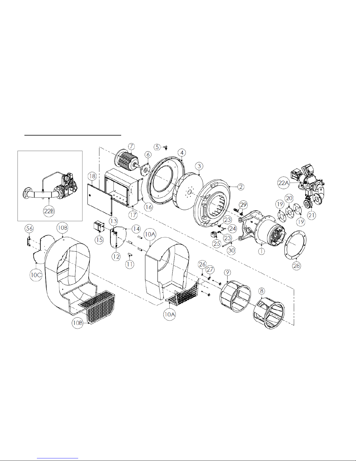
Operating Instructions For TD/TAD4 Dual Fuel Burner
June 13 85 of 165 TD/TAD4 Manual Rev 4
11 Exploded Diagram & Spare Parts List
11.1 Modulating Oil Modulating Gas Setup
Page 86
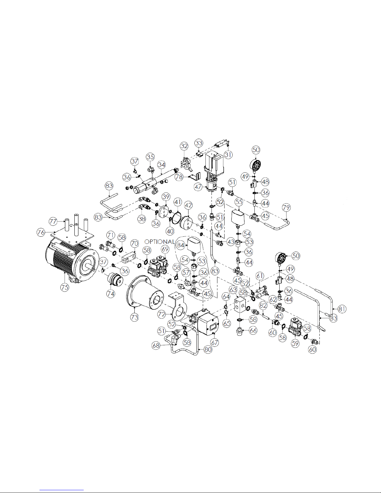
Operating Instructions For TD/TAD4 Dual Fuel Burner
June 13 86 of 165 TD/TAD4 Manual Rev 4
Page 87

Operating Instructions For TD/TAD4 Dual Fuel Burner
June 13 87 of 165 TD/TAD4 Manual Rev 4
ITEM
QTY.
DESCRIPTION
DWG/PART No.
1
1
TD410 LOW NOx COMBUSTION HEAD ASSEMBLY
TD415-420 LOW NOx COMBUSTION HEAD ASSEMBLY
TD410 COMBUSTION HEAD ASSEMBLY
TD415-420 COMBUSTION HEAD ASSEMBLY
GA23554
GA23555
GA23556
GA23558
2
1
T4 VANE CASTING
GA08715
3
1
T410 FAN IMPELLOR (WHITE)
T415 FAN IMPELLOR (BLUE)
T420 FAN IMPELLOR (BLACK
GA8765
GA8764
GA8763
4
1
T4 BODY (FAN HALF)
GA08716
5 1 EYEBOLT T4 16MM 58mm O/D x32mm I/D
EYEBLT00100
7
1
TD410 7.5KW FAN MOTOR
TD415 11KW FAN MOTOR
TD420 15KW FAN MOTOR
MOTORF01210
MOTORF01235
MOTORF01250
8
1
ANODISE OUTER SHUTTER TD410, TD415
ANODISE OUTTER SHUTTER TD420
GA15127
GA17290
9
1
ANODISE INNER SHUTTER TD410, TD415
ANODISE INNER SHUTTER TD420
GA15125
GA17210
10A
1
SILENCER FOR TD410, TD415
SILENCER FOR TD420
GA08891
GA08893
10B
1
T410/415 SNORKEL SILENCER WITH CHAMFERED CORNERS
T420 SNORKEL SILENCER WITH CHAMFERED CORNERS
GA21875
GA21504
10C
1
SNORKEL SILENCER MESH
GA16838
11
1
SPACER FOR MOD PLATE
GA07961
12
2
ROD END BEARING
BEAROS00250
13
1
SERVO MOTOR LINKARM
GA18765
14
1
MOD PLATE
GA17188
15 1 ETC6027 CANBUS SERVO MOTOR 12Nm
ETCRAT00745
16 1 T4 CONTROL PANEL MOUNTING BRACKET
GA9093
17
1
542 ELECTRICAL ENCLOSURE
552 ELECTRICAL ENCLOSURE
667 ELECTRICAL ENCLOSURE
GA10724
GA10720
GA12409
18
1
DOOR FOR 542 ELECTRICAL ENCLOSURE
DOOR FOR 552 ELECTRICAL ENCLOSURE
DOOR FOR 667 ELECTRICAL ENCLOSURE
GA10726
GA10722
GA10723
19
1
SIDE ENTRY GASKET
GA08990
20
1
GAS TRAIN FLANGE 80
GA07099
21
1
BUTTERFLY VALVE 80mm
GA17187
22A
1
T4 UNIBLOC SIDE ENTRY ASSEMBLY DN65
T4 UNIBLOC SIDE ENTRY ASSEMBLY DN80
T4 UNIBLOC SIDE ENTRY ASSEMBLY DN100
GA23518A
GA23518B
GA23518C
22B
1
T4 VGD40 SIDE ENTRY ASSEMBLY DN65
T4 VGD40 SIDE ENTRY ASSEMBLY DN80
T4 VGD40 SIDE ENTRY ASSEMBLY DN100
GA23529A
GA23529B
GA23529C
23 1 MALE STUD COUPLING 10MM x 3/8" BSP
COMPAD00490
24
1
10mm BUNDI TUBE
BUNDIT00145
25
1
PRESSURE SWITCH
PRESWI00246
26
1
INNER NYLON ROLLER
GA5761A
27
1
OUTER NYLON ROLLER
GA5761B
28
1
Z TYPE MOUNTING GASKET
Y TYPE MOUNTING GASKET
GA11741
GA11742
29
1
QRA2 UV CELL WITH BRACKET
12041
Page 88

Operating Instructions For TD/TAD4 Dual Fuel Burner
June 13 88 of 165 TD/TAD4 Manual Rev 4
30
1
JACKING SCREW
FASHEX00150
31
2
OIL ELECTRODE
IGELEC00110
32
1
OIL TUBE SUPPORT SPIDER
GA12370
33
4
SPLIT ELECTRODE BUSH
GA8264
34
1
ART1400 BURNER GUN
GA21876
35
2
POSITIONAL ELBOW 10-4L 10mm
COMPAD00550
36
12
1/4"BSP DOWTY 'BONDED' SEAL
SEADOW00105
37
4
1/4" BSP YORKSHIRE FTG. BRASS PLUG
YORFIT00510
38
2
SWIVEL ELBOW 10mm MSE 10-4 L
COMPAD00505
39
1
TWIN PORT SANDWICH BLOCK (INSIDE)
GA9178A
40
2
SANDWICH BLOCK INNER O-RING
ORINGS00180
41
1
SANDWICH BLOCK OUTER O-RING
0RINGS01025
42 1 TWIN PORT SANDWICH BLOCK (OUTSIDE)
GA9178B
43 1 MALE STUD COUPLING 10mm MMC 10-4 L
COMPAD00485
44 5 STANDPIPE ADAPTOR 10mm MSA 10-4 L
COMPAD00535
45
3
EQUAL TEES 10mm 10 L
COMPAD00520
46
4
MOTOR HANGER PLATE SPACER
GA7961
47 1 VARIOTRONIC OIL METERING VALVE ASSEMBLY
GA16090
48
2
1/4" MINI BALL VALVE
VALOIL00110
49
2
M5 COPPER WASHER
COPWAS00025
50
2
0 - 600 PSI PRESSURE GUAGE
PRESGA00100
51 3 MALE STUD COUPLING 10mm X 3/8" MMC 10-6 L
COMPAD00490
52
4
3/8"BSP DOWTY 'BONDED' SEAL
SEADOW00100
53
2
PRESSURE SWITCH ADAPTOR
BANMAN00170
54
2
1/4" COPPER WASHER
COPWAS00075
55
1
SAUTER HIGH OIL PRESSURE SWITCH
BAILEY HIGH OIL PRESSURE SWITCH
PRESWI00570
PRESWI00700
56
1
BRIDGE HANDLE
CONTOL02285
57 2 STANDPIPE ADAPTORS 10mm MSA 10-8 L
COMAD00545
58
12
1/2"BSP DOWTY 'BONDED' SEAL
SEADOW00110
59
1
1/2" LUCIFER OIL SOLENOID VALVE
SOLOIL00360
60 3 MALE STUD COUPLING 10mm x 1/2" MMC 10-8 L
COMPAD00495
61
1
3/8" BSP BANJO BOLT #7 x 70
GA10382
62
1
1/2" BSP BANJO BOLT #4 x 72
GA10143
63
1
MANIFOLD No. 4 WITH VALVE CLUSTER
GA16780
64
1
COPPER WASHER 3/8"
COPWAS00100
65
1
COPPER WASHER 1/2"
COPWAS00110
66
1
1"BSP 'HEAVYWEIGHT' BARREL NIPPLE
PIPNIP01340
67
1
DH1-1-CLOCKWISE ROTATION
DH1-2-CLOCKWISE ROTATION
DH1-1-ANTI-CLOCKWISE ROTATION
DH1-1-ANTI-CLOCKWISE
PUMDUN01012
PUMDUN01010
PUMDUN01025
PUMDUN01020
68
1
POSITIONAL ELBOW 3/4" x 1/2"
CONELB00125
69
2
OIL SOL VALVE LUCIFER 1/2" N/C
SOLOIL00240
70
1
OIL MANIFOLD No. 1
GA16777
71
2
1/2" BSP BANJO BOLT #3 x 54
GA10125
72 1 MOUNTING BRACKET FOR VALVE CLUSTER FITTET TO DH-1
GA10190
73
1
D.90 MOTOR BELL HOUSING
GA05900
74
1
PUMP COUPLING ASSEMBLY
PUMZCP00665
Page 89

Operating Instructions For TD/TAD4 Dual Fuel Burner
June 13 89 of 165 TD/TAD4 Manual Rev 4
75
1
1.1kW 2 POLE PUMP MOTOR
MOTPUM00120
76
1
MOTOR HANGER BRACKET
GA10450
77
1
BERGER LAHR SERVO MOTOR
SERVBLO00100
78 1 VARIOTRONIC OIL VALVE MOUNTING BRACKET
GA16089
79
1
10mm DIAMETER BUNDI TUBE
GA23514A
80
1
10mm DIAMETER BUNDI TUBE
GA23514B
81
1
10mm DIAMETER BUNDI TUBE
GA23514C
82
1
10mm DIAMETER BUNDI TUBE
GA23514D
83
-
10mm DIAMETER BUNDI TUBE
BUNDIT00115
84
1
SAUTER LOW OIL PRESSURE SWITCH
BAILEY LOW OIL PRESSURE SWITCH
PRESWI00400
PRESWI00705
Page 90
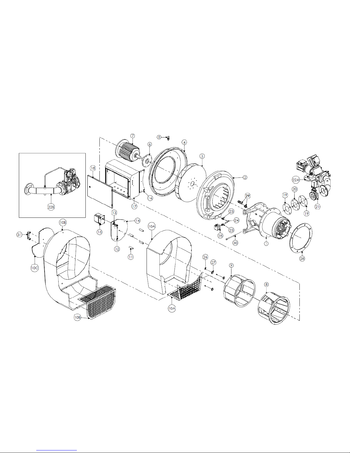
Operating Instructions For TD/TAD4 Dual Fuel Burner
June 13 90 of 165 TD/TAD4 Manual Rev 4
11.2 Modulating Oil Modulating Gas with DH2 Pump (TD420 Only)
Page 91

Operating Instructions For TD/TAD4 Dual Fuel Burner
June 13 91 of 165 TD/TAD4 Manual Rev 4
Page 92

Operating Instructions For TD/TAD4 Dual Fuel Burner
June 13 92 of 165 TD/TAD4 Manual Rev 4
ITEM
QTY.
DESCRIPTION
DWG/PART No.
1
1
TD415-420 LOW NOx COMBUSTION HEAD ASSEMBLY
TD415-420 COMBUSTION HEAD ASSEMBLY
GA23555
GA23558
2
1
T4 VANE CASTING
GA08715
3
1
T410 FAN IMPELLOR (WHITE)
T415 FAN IMPELLOR (BLUE)
T420 FAN IMPELLOR (BLACK
GA8765
GA8764
GA8763
4
1
T4 BODY (FAN HALF)
GA08716
5
1
EYEBOLT T4 16MM 58mm O/D x32mm I/D
EYEBLT00100
7
1
TD420 15KW FAN MOTOR
MOTORF01250
8
1
ANODISE OUTER SHUTTER TD420
GA17290
9
1
ANODISE INNER SHUTTER TD420
GA17210
10A
1
SILENCER FOR TD420
GA08893
10B 1 T420 SNORKEL SILENCER WITH CHAMFERED CORNERS
GA21504
10C
1
SNORKEL SILENCER MESH
GA16838
11
1
SPACER FOR MOD PLATE
GA07961
12
2
ROD END BEARING
BEAROS00250
13
1
SERVO MOTOR LINKARM
GA18765
14
1
MOD PLATE
GA17188
15
1
ETC6027 CANBUS SERVO MOTOR 12Nm
ETCRAT00745
17
1
542 ELECTRICAL ENCLOSURE
552 ELECTRICAL ENCLOSURE
667 ELECTRICAL ENCLOSURE
GA10724
GA10720
GA12409
18
1
DOOR FOR 542 ELECTRICAL ENCLOSURE
DOOR FOR 552 ELECTRICAL ENCLOSURE
DOOR FOR 667 ELECTRICAL ENCLOSURE
GA10726
GA10722
GA10723
19
1
SIDE ENTRY GASKET
GA08990
20
1
GAS TRAIN FLANGE 80
GA07099
21
1
BUTTERFLY VALVE 80mm
GA17187
22A
1
T4 UNIBLOC SIDE ENTRY ASSEMBLY DN65
T4 UNIBLOC SIDE ENTRY ASSEMBLY DN80
T4 UNIBLOC SIDE ENTRY ASSEMBLY DN100
GA23518A
GA23518B
GA23518C
22B
1
T4 VGD40 SIDE ENTRY ASSEMBLY DN65
T4 VGD40 SIDE ENTRY ASSEMBLY DN80
T4 VGD40 SIDE ENTRY ASSEMBLY DN100
GA23529A
GA23529B
GA23529C
23
1
MALE STUD COUPLING 10MM x 3/8" BSP
COMPAD00490
24
1
10mm BUNDI TUBE
BUNDIT00145
25
1
PRESSURE SWITCH
PRESWI00246
26
1
INNER NYLON ROLLER
GA5761A
27
1
OUTER NYLON ROLLER
GA5761B
28
1
Y TYPE MOUNTING GASKET
GA11742
29
1
QRA2 UV CELL WITH BRACKET
12041
30
1
JACKING SCREW
FASHEX00150
31
1
BRIDGE HANDLE
CONTOL02285
32
1
BRIDGE HANDLE
CONTOL02285
33
1
FLAME PLATE
GA10613
34
2
IGNITION ELECTRODE
IGELEC00110
35
4
OIL TUBE SUPPORT SPIDER
GA8264
36
1
SHELL HEAD FOR OIL BURNERS
GA8233A
37
1
ART1400 OIL BURNER GUN
GA21876
38
2
POSITIONAL ELBOW 10-4L
COMPAD00550
Page 93

Operating Instructions For TD/TAD4 Dual Fuel Burner
June 13 93 of 165 TD/TAD4 Manual Rev 4
39
12
1/4"BSP DOWTY 'BONDED' SEAL
SEADOW00105
40
4
1/4" BSP YORKSHIRE BRASS PLUG
YORFIT00510
41
2
SWIVEL ELBOW 10mm MSE 10-4 L
COMPAD00505
42 1 MALE STUD COUPLING 12mm MMC 12-4 L
COMPAD00430
43 5 MALE STUD COUPLING 12mm X 3/8" MMC 12-6 L
COMPAD00420
44
5
3/8"BSP DOWTY 'BONDED' SEAL
SEADOW00100
45
1
VARIOTRONIC OIL METERING VALVE ASSEMBLY & PARTS
LIST
GA16090
46 1 VARIOTRONIC OIL VALVE MOUNTING BRACKET
GA16089
47
1
BERGER LAHR SERVO MOTOR
30039
48
3
EQUAL TEES 12mm 12 L
COMPAD00455
49
2
1/4" MINI BALL VALVE MBV 14S
VALOIL00110
50
2
M5 FLAT COPPER WASHER
COPWAS00025
51
2
0 - 600 PSI PRESSURE GUAGE
PRESGA00100
52 2 STANDPIPE ADAPTORS 12mm MSA 12-8 L
COMAD00480
53
11
1/2"BSP DOWTY 'BONDED' SEAL
SEADOW00110
54
2
OIL SOL VALVE LUCIFER 1/2" N/C
SOLOIL00240
55
1
OIL MANIFOLD No. 1
GA16777
56
2
1/2" BSP BANJO BOLT #3 x 54
GA10125
57 3 MALE STUD COUPLING 12mm x 1/2" MMC 12-8 L
COMPAD00425
58
1
SAUTER LOW OIL PRESSURE SWITCH
BAILEY LOW OIL PRESSURE SWITCH
PRESWI00400
PRESWI00705
59
1
OIL SOL VALVE LUCIFER 1/2" N/C 230V
SOLOIL00360
60
1
1/2" BSP BANJO BOLT #8 x 72
GA10400
61
1
3/4" BSP BANJO BOLT #9 x 72
GA10401
62 1 MANIFOLD No. 6U WITH DH-2 VALVE CLUSTER
GA16771
63
1
REDUCING NIPPLE, 1"-3/4"
PIPNIP01450
64
1
COPPER WASHER 1/2"
COPWAS00110
65
1
COPPER WASHER 3/4"
COPWAS00115
66
1
DH2 PUMP SERIES
PUMDUN02013
PUMDUN02014
PUMDUN02015
PUMDUN02016
67
3
3/4" BSP DOWTY SEAL
SEADOW00120
68
1
POSITIONAL ELBOW 1" x 3/4"
CONELB00125
69
1
MOUNTING FLANGE DH2 FUEL UNIT
GA7928
70 1 MOUNTING BRACKET FOR VALVE CLUSTER FITTET TO DH-2
GA10228
71
1
D.90 MOTOR BELL HOUSING
GA05900
72
1
PUMP COUPLING
PUMZCP00665
73
1
3kW 2 POLE PUMP MOTOR
MOTPUM00310
74
1
MOTOR HANGER BRACKET
GA20791
75
2
PRESSURE SWITCH ADAPTOR
BANMAN00170
76
2
1/4" COPPER WASHER
COPWAS00075
77
1
SAUTER HIGH OIL PRESSURE SWITCH
BAILEY HIGH OIL PRESSURE SWITCH
PRESWI00570
PRESWI00700
78
1
10mm BUNDI TUBE
GA23870A
79
1
10mm BUNDI TUBE
GA23870B
80
1
10mm BUNDI TUBE
GA23870C
Page 94
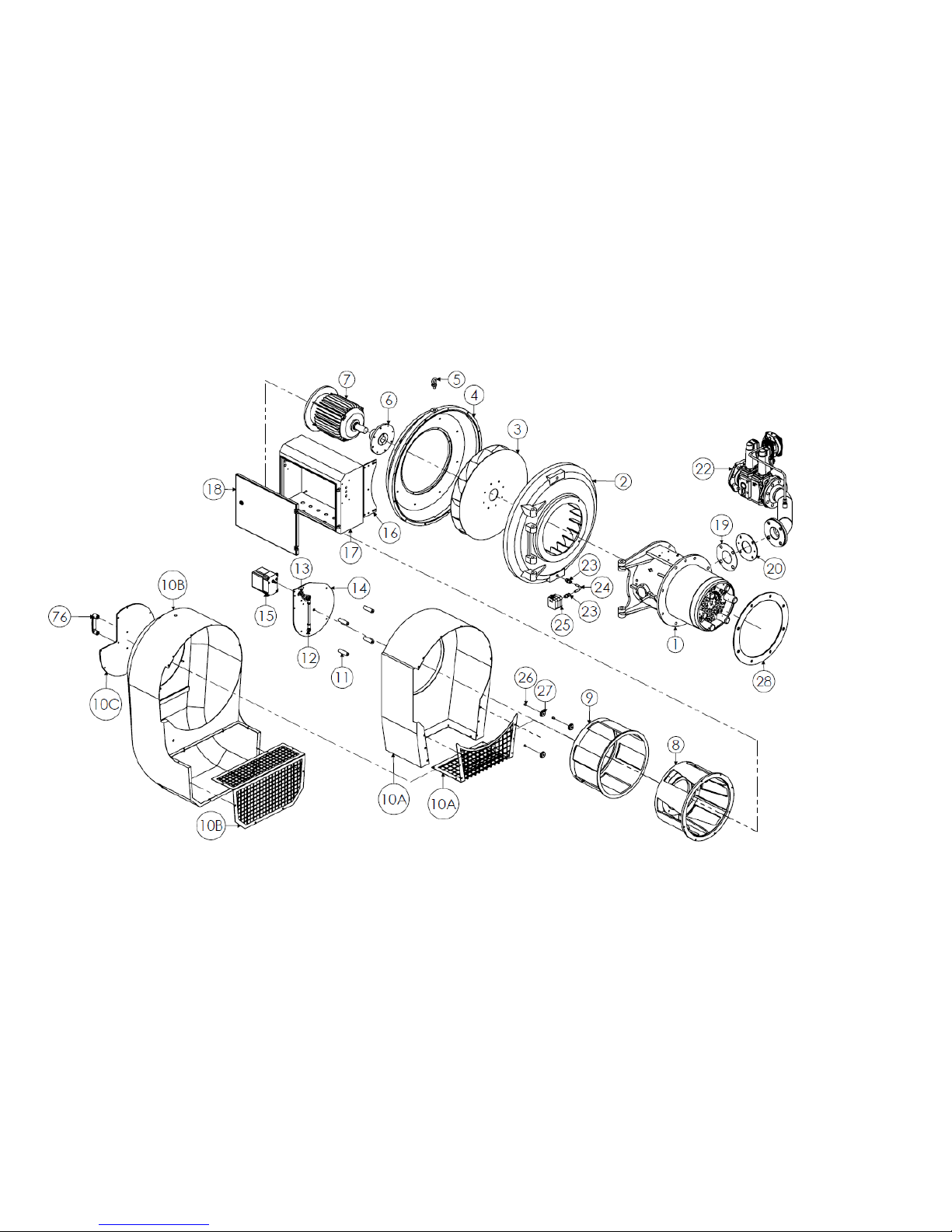
Operating Instructions For TD/TAD4 Dual Fuel Burner
June 13 94 of 165 TD/TAD4 Manual Rev 4
11.3 High Low Oil High Low Gas Setup (TD410 Only)
Page 95
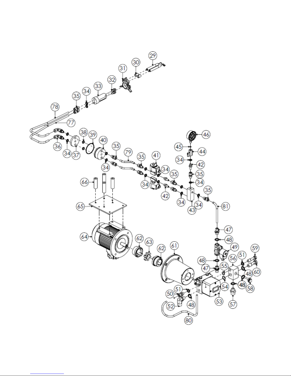
Operating Instructions For TD/TAD4 Dual Fuel Burner
June 13 95 of 165 TD/TAD4 Manual Rev 4
Page 96

Operating Instructions For TD/TAD4 Dual Fuel Burner
June 13 96 of 165 TD/TAD4 Manual Rev 4
ITEM
QTY.
DESCRIPTION
DWG/PART No.
1
1
TD410 LOW NOx COMBUSTION HEAD ASSEMBLY
TD410 COMBUSTION HEAD ASSEMBLY
GA23554
GA23556
2
1
T4 VANE CASTING
GA08715
3
1
T410 FAN IMPELLOR (WHITE)
T415 FAN IMPELLOR (BLUE)
T420 FAN IMPELLOR (BLACK
GA8765
GA8764
GA8763
4
1
T4 BODY (FAN HALF)
GA08716
5 1 EYEBOLT T4 16MM 58mm O/D x32mm I/D
EYEBLT00100
7
1
TD410 7.5KW FAN MOTOR
MOTORF01210
8
1
ANODISE OUTER SHUTTER TD410, TD415
GA15127
9
1
ANODISE INNER SHUTTER TD410, TD415
GA15125
10A
1
SILENCER FOR TD410, TD415
GA08891
GA08893
10B 1 T410/415 SNORKEL SILENCER WITH CHAMFERED CORNERS
GA21875
10C
1
SNORKEL SILENCER MESH
GA16838
11
4
SPACER FOR MOD PLATE
GA07961
12
2
ROD END BEARING
BEAROS00250
13
1
SERVO MOTOR LINKARM
GA18765
14
1
MOD PLATE
GA17188
15 1 ETC6027 CANBUS SERVO MOTOR 12Nm
ETCRAT00745
16 1 T6 CONTROL PANEL MOUNTING BRACKET
GA9093
17
1
542 ELECTRICAL ENCLOSURE
552 ELECTRICAL ENCLOSURE
667 ELECTRICAL ENCLOSURE
GA10724
GA10720
GA12409
18
1
DOOR FOR 542 ELECTRICAL ENCLOSURE
DOOR FOR 552 ELECTRICAL ENCLOSURE
DOOR FOR 667 ELECTRICAL ENCLOSURE
GA10726
GA10722
GA10723
19
1
SIDE ENTRY GASKET
GA08990
20
1
GAS TRAIN FLANGE 80
GA07099
21
- - -
22
1
T4 VGD40 SIDE ENTRY ASSEMBLY DN65
T4 VGD40 SIDE ENTRY ASSEMBLY DN80
T4 VGD40 SIDE ENTRY ASSEMBLY DN100
GA23524A
GA23524B
GA23524C
23 1 MALE STUD COUPLING 10MM x 1/4" BSP
COMPAD00485
24
1
10mm BUNDI TUBE
BUNDIT00145
25
1
PRESSURE SWITCH
PRESWI00246
Page 97

Operating Instructions For TD/TAD4 Dual Fuel Burner
June 13 97 of 165 TD/TAD4 Manual Rev 4
26
1
INNER NYLON ROLLER
GA5761A
27
1
OUTER NYLON ROLLER
GA5761B
28
1
MOUNTING GASKET
GA11741
29
2
OIL ELECTRODE
IGELEC00110
30
4
SPLIT ELECTRODE BUSH
GA8264
31
1
OIL TUBE SUPPORT SPIDER
GA12370
32
2
HIGH LOW OIL NOZZLE
SEE PROD. SHEET
33
2
TWIN NOZZLE BLOCK
GA5406
34
15
1/4"BSP DOWTY 'BONDED' SEAL
SEADOW00105
35
10
MALE STUD COUPLING 10mm MMC 10-4 L
COMPAD00485
36
2
SWIVEL ELBOW 10mm MSE 10-4 L
COMPAD00505
37
1
TWIN PORT SANDWICH BLOCK (INSIDE)
GA9178A
38
2
SANDWICH BLOCK INNER O-RING
ORINGS00180
39
1
SANDWICH BLOCK OUTER O-RING
0RINGS01025
40 1 TWIN PORT SANDWICH BLOCK (OUTSIDE)
GA9178B
41
2
1/4" LUCIFER OIL SOLENOID VALVE
SOLOIL00260
42 2 STANDPIPE ADAPTOR 10mm MSA 10-4 L
COMPAD00535
43
1
1/4" BSP OIL MANIFOLD BLOCK 4 PORT
GA13237
44
1
1/4" MINI BALL VALVE
VALOIL00110
45
1
M5 COPPER WASHER
COPWAS00025
46
2
0 - 600 PSI PRESSURE GUAGE
PRESGA00100
47 2 MALE STUD COUPLING 10mm x 1/2" MMC 10-8 L
COMPAD00495
48
6
1/2"BSP DOWTY 'BONDED' SEAL
SEADOW00110
49
1
1/2" LUCIFER OIL SOLENOID VALVE
SOLOIL00240
50 2 MALE STUD COUPLING 10mm X 3/8" MMC 10-6 L
COMPAD00490
51
2
3/8"BSP DOWTY 'BONDED' SEAL
SEADOW00100
52
1
POSITIONAL ELBOW 3/4" x 1/2"
CONELB00125
53
1
DH1-1-CLOCKWISE ROTATION
DH1-2-CLOCKWISE ROTATION
DH1-1-ANTI-CLOCKWISE ROTATION
DH1-1-ANTI-CLOCKWISE
PUMDUN01012
PUMDUN01010
PUMDUN01025
PUMDUN01020
54
1
COPPER WASHER 1/2"
COPWAS00110
55
1
COPPER WASHER 3/8"
COPWAS00100
56
1
MANIFOLD No. 4 WITH VALVE CLUSTER
GA16780
57
1
1"BSP 'HEAVYWEIGHT' BARREL NIPPLE
PIPNIP01340
58
1
1/2" BSP YORKSHIRE FITTING
YORFIT00530
59
1
3/8" BSP BANJO BOLT #7 x 70
GA10382
60
1
1/2" BSP BANJO BOLT #4 x 72
GA10143
70
1
D.90 MOTOR BELL HOUSING
GA05900
Page 98

Operating Instructions For TD/TAD4 Dual Fuel Burner
June 13 98 of 165 TD/TAD4 Manual Rev 4
71
2
PUMP COUPLING
PUMZCP00665
72
1
PUMP COUPLING INSERT
PUMZCP00665
73
1
1.1kW 2 POLE PUMP MOTOR
MOTPUM00120
74
1
MOTOR HANGER BRACKET
GA10450
75
4
MOTOR HANGER BRACKET SPACER
GA7961
76
1
BRIDGE HANDLE
CONTOL02285
77
1
10mm BUNDI TUBE
GA23517A
78
1
10mm BUNDI TUBE
GA23517B
79
2
10mm BUNDI TUBE
GA23517C
80
1
10mm BUNDI TUBE
GA23517D
81
1
10mm BUNDI TUBE
BUNDIT00115
Page 99
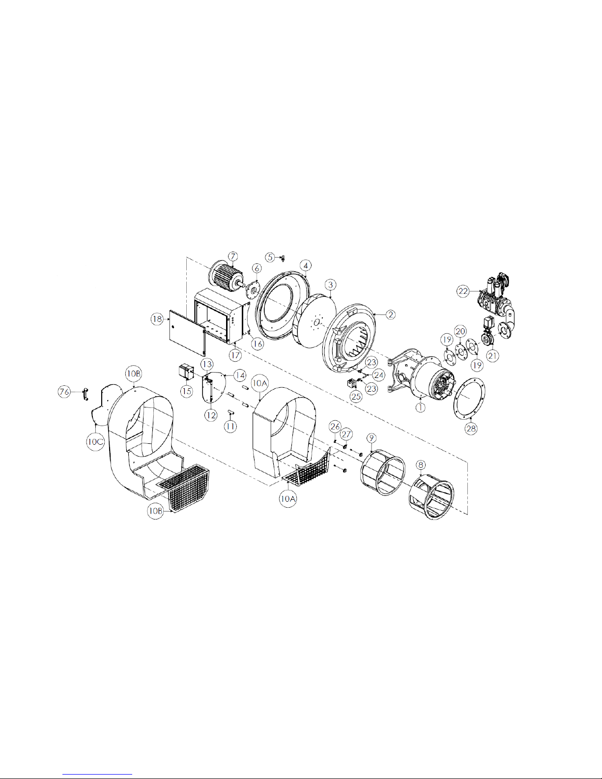
Operating Instructions For TD/TAD4 Dual Fuel Burner
June 13 99 of 165 TD/TAD4 Manual Rev 4
11.3 Modulating Gas High Low Oil Setup (TD410 Only)
Page 100
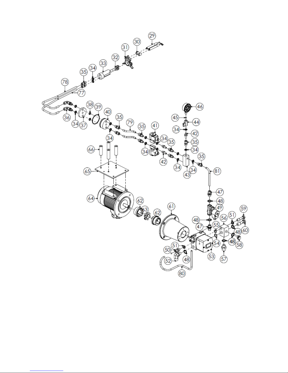
Operating Instructions For TD/TAD4 Dual Fuel Burner
June 13 100 of 165 TD/TAD4 Manual Rev 4
 Loading...