

Page 1

92503014502revA
CSP099 PHASE 99
Page 2
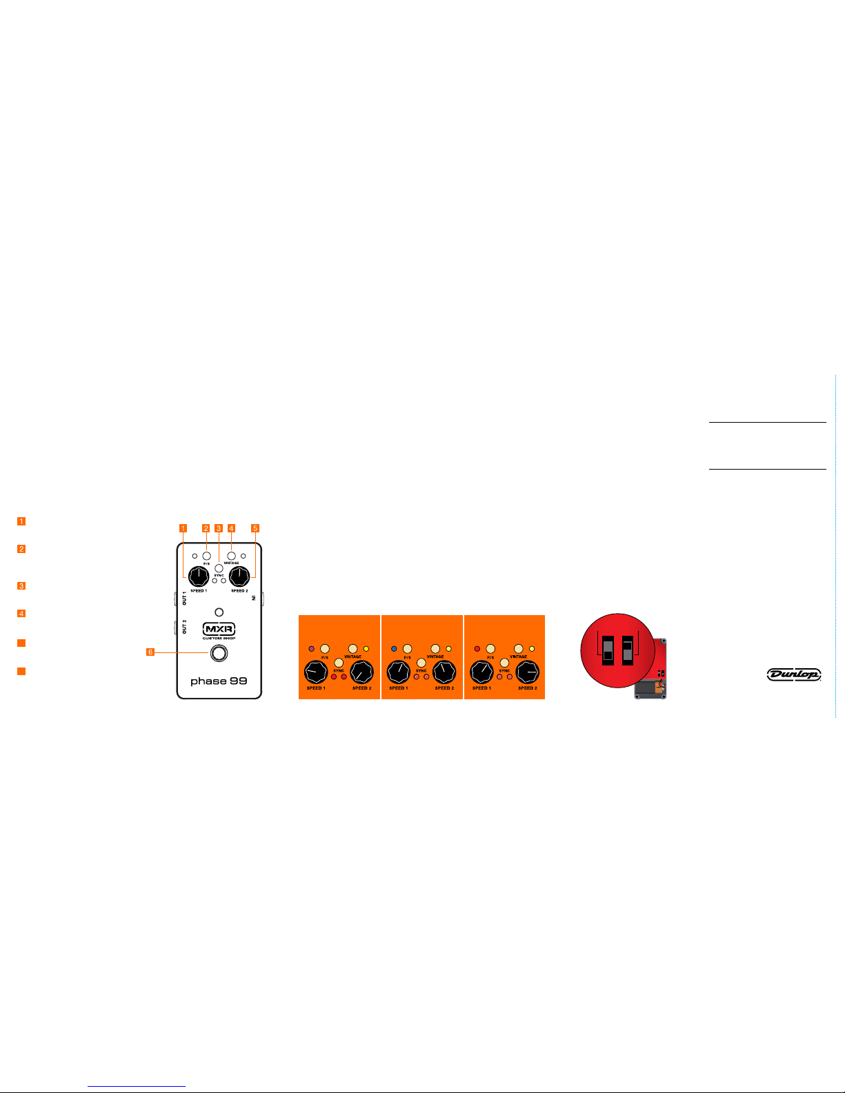
SAMPLE SETTINGS
CSP099 PHASE 99
POWER
The MXR Phase 99 is powered
by one 9-volt battery (remove
bottom plate to install), a 9-volt
AC adapter such as the Dunlop
ECB003/ECB003E, or a DC Brick™
power supply.
DESCRIPTION
• Two Phase 90 circuits in one
Phase 90-sized pedal
• Run both circuits independently
or feed one into the other
• Toggle between modern and
vintage phase sounds
DUNLOP MANUFACTURING, INC.
P.O. BOX 846 BENICIA, CA 94510 U.S.A.
TEL: 1-707-745-2722 FAX: 1-707-745-2658
CONTROLS
SPEED 1 knob controls rate of
Phase 1 circuit (indicated by
ashing red left-side LED)
P/S switch toggles signal ow
of phase circuits from parallel
(bluish purple LED) to series
(blue LED)
SYNC switch sweeps both
phase circuits at the rate of
the SPEED 1 control
VINTAGE switch engages
vintage phase voice
(indicated by yellow LED)
5 SPEED 2 knob controls rate of
Phase 2 circuit (indicated by
ashing red right-side LED)
6 FOOTSWITCH toggles
effect on/bypass (red LED
indicates on)
DIRECTIONS
• Run a cable from your guitar to
the Phase 99’s IN jack and run
another cable from the Phase
99’s OUT 1 jack to your amplier.
Optional: Run another cable from
the Phase 99’s OUT 2 jack to a
separate amplier to run each
phase circuit in stereo (Parallel
Mode).
• Start with all controls at
12 o’clock.
• Turn the effect on by
depressing the footswitch.
• Rotate the SPEED 1 knob
clockwise to increase the
rate of the Phase 1 circuit or
counterclockwise to decrease it.
• Rotate the SPEED 2 knob
clockwise to increase the
rate of the Phase 2 circuit or
counterclockwise to decrease it.
INTERNAL SW6 SWITCH
SW6 toggles Phase 1 and 2 mixing
on/off when OUT 2 is unplugged
(mono) and Parallel Mode is
selected. To mix both phase signals
and send them to OUT 1, set the
SW6 switch to its “down” position.
This is the default factory setting.
When SW6 is “up,” only Phase 1
will be heard from OUT 1, and the
Parallel Mode LED will become red.
Plugging into both OUT 1 and OUT
2 (stereo) in Parallel Mode results
in Phase 1 going to OUT 1 and
Phase 2 going to OUT 2, regardless
of SW6’s position. In Series Mode,
SW6 has no effect.
Note: SW5 switch should always
be left in its “up” position.
• To synchronize the sweep rate
of both phase circuits, push the
SYNC switch. The SPEED 1 knob
will then control the rate of both
circuits, and the SPEED 2 knob
will be inactive.
• To run both phase circuits in
Parallel Mode, set the P/S switch
to its “up” position (bluish purple
LED). To run Phase 1 and Phase 2
in Series Mode and create a more
intense effect with exaggerated
frequency cuts and peaks, set the
P/S switch to its “down” position
(blue LED).
• To change the tonal character
of the phase circuits from
modern to vintage, push
the VINTAGE switch.
SPECIFICATIONS
Input Impedance 450 kΩ
Output Impedance 2 kΩ
Nominal Input 20 dBV
Max Output 20 dBV
Noise Floor
Series Mode -95 dBV
Parallel Mode -101 dBV
Bypass Hardwire
Current Draw 24 mA
Power Supply 9 volts DC
NOTE: Actual measured values are
with a 10% add on to worse case
condition
.
SW6 SW5
INTERNAL CONTROLS
(factory settings)
SUBTLE PHASE DEEP VIBE
REVOLVING HORN
& DRUM
(stereo outs)
(OUT) (IN)
(IN) (OUT) (OUT)
(IN) (OUT) (OUT)(OUT)
 Loading...