

Page 1

XEB Series
Gas-FiredHot Water
Induced Draft Boilers
INSTALLATION, OPERATION &
MAINTENANCE MANUAL
DUNKIRK BOILERS
85 Middle Rd.
Dunkirk, NY 14048
www. dunkirk, corn
P/N14683001 Rev.B[11/09]
Page 2
Safety Symbols ........................................................................................................................................................ 2
Installation Instructions ......................................................................................................................................... 3
Boiler Ratings And Capacities ................................................................................................................................ 3
Before You Start ...................................................................................................................................................... 4
Locating The Boiler ................................................................................................................................................. 5
Fresh Air For Combustion ....................................................................................................................................... 6
Installation System Piping .................................................................................................................................. 10
Chimney & Vent Pipe Connection ....................................................................................................................... 12
Horizontal Venting Instructions ....................................................................................................................... 15
Optional Horizontal Venting Instruction ........................................................................................................... 20
Gas supply Piping ................................................................................................................................................ 21
Electrical Wiring ................................................................................................................................................... 22
Sequence of Operation ........................................................................................................................................ 22
Wiring Diagrams .................................................................................................................................................. 23
Equipment & Optional Accessories .................................................................................................................... 24
Starting Your Boiler ............................................................................................................................................. 26
Checking and Adjusting ...................................................................................................................................... 27
Initial Operational Boiler Test Check-Out Procedure ........................................................................................ 29
Maintaining Your Boiler ...................................................................................................................................... 31
Service Hints ......................................................................................................................................................... 32
IMPORTANT:Readthe followinginstructions COM-
PLETELYbeforeinstalling!
Keepthis manual near boiler and retainfor future refer-
ence.
Thefollowingdefined symbolsareused throughout this manual to notify the reader ofpotential hazards ofvarying risk levels.
Indicates an imminently hazardous situation which, ifnot
avoided,WILLresult in death, serious injury or substantial
property damage.
Indicates an imminently hazardous situation which, ifnot
avoided,may result in injury or property damage.
Indicates an imminently hazardous situation which, ifnot
avoided,may result in death, serious injury or substantial
property damage.
Indicates information which shouldbe followedto ensure
proper installationand operation.
C.S.A. Certified for
Natural gas or Propane
Tested for 50 Ibs. ASME
Working Pressure
Page 3
Theseinstructions must be affixedon or adjacent to the boiler.
Thisboiler cannot be usedwith alltypes ofchimneys.Read these
instructions carefullybefore installing.
TheseGas-Fired HotWater Boilersare lowpressure, sectionalcast
iron boilers Design Certifiedby C.S.A.(Canadian StandardsAssoci-
ation) foruse with Natural and Propane Gases.Theyare constructed
and hydrostaticallytested for amaximum workingpressure of 50psi
in accordancewith A.S.M.E.Boilerand PressureVesselCode Sec-
tion IV Standardsfor castiron heating boilers.
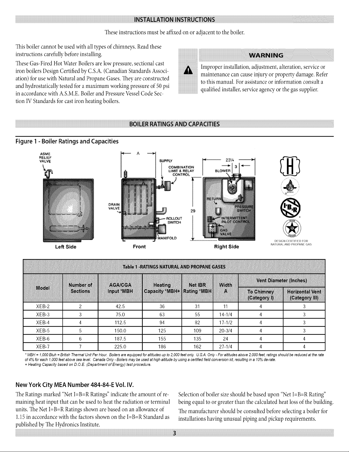
Figure 1 - Boiler Ratings and Capacities
ASME
R_LIEF
VALVE
iiiiiiiiiiiiiiii
iiiiiiiiiiiiiiiiiiiiiiiiiiiiiiiiiiiiiiiiiiiiii
iiiiiiiiiiiiiiiiiiiiiiiiiiiiiiiiiiiiiiiiiiiii_
iiiiiiiiiiiiiiiiiiiiiiiiiiiiiiiiiiiiiiiiiiiiii
iiiiiiiiiiiiiiiiiiiiiiiiiiiiiiiiiiiiiiiiiiiiii
iiiiiiiiiiiiiiiiiiiiiiiiiiiiiiiiiiiiiiiiiiiiii
Improper installation, adjustment, alteration, serviceor
maintenance can cause injuryor property damage.Refer
to this manual. For assistanceor information consult a
qualifiedinstaller,serviceagency or thegas supplier.
\,® .
VALVE
DESIGN CERTIFIED FOR
LeR Si_e Fro_t Right Side
XEB-2 2 42.5 36 31 11 4 3
XEB-3 3 75.0 63 55 14-1/4 4 3
XEB-4 4 112.5 94 82 17-1/2 4 3
XEB-5 5 150.0 125 109 20-3/4 4 3
XEB-6 6 187.5 155 135 24 4 4
XEB-7 7 225.0 186 162 27-1/4 4 4
*MBH = f,O00 Btuh = British Thermal Unit Per Hou_ Boilers areequipped foraltitudes up to 2,000 feet on!_ U.S.A. Only - For altitudes above 2,000 feet, ratings should be reducedat therate
of 4% for each f,O00feet above sealevel. Canada Only -Boilers may be used at high altitude by using a certified field conversion kit, resulting in a 10%de-rate.
+ Heating Capacity based on D.O.E. (Department of Energy) testprocedure.
NATURAt AND PROPANE GAS
New York City MEA Number 484-84-E Vol. IV.
TheRatingsmarked "Net I=B=RRatings"indicate the amount of re-
maining heat input that can be usedto heat the radiation or terminal
units. The Net I=B=RRatingsshown are based on an allowanceof
1.15in accordancewith thefactors shownon the I=B=RStandard as
publishedby TheHydronicsInstitute.
Selectionofboiler sizeshould be basedupon "NetI=B=RRating"
being equalto or greaterthan the calculated heat lossofthe building.
Themanufacturer shouldbe consulted before selecting a boiler for
installations havingunusual piping and pickup requirements.
Page 4

iiiiiiiiiiiiiiiiiiiiiiiiiiiiiiiiiiiiiiiiiiiiiiiiiiiiiiiiiiiiiiiiiiiiiiiiiiiiiiiiiiiiiiiiiiiiiiiiiiiiiiiiiiiiiiiiiiiiiiiiiiiiiiiiiiiiiiiiiiiiiiiiiiiiiiiiiiiiiiiiiiiiiiiiiiiiiiiiiiiiiiiiiiiiiiiiiiiiiiiiiiiiiiiiiiiiiiiiiiiiiiiiiiiiiiiiiiiiiiiiiiiiiiiiiiiiiiiiiiiiiiiiiiiiiiiiiiiiiiiiiiiiiiiiiiiiiiiiiiiiiiiiiiiiiiiiiiiiiiiiiiiiiiiiiiiiiiiiiiiiiiiiiiiiiiiiiiiiiiiiiiiiiiiiiiiiiiiiiiiiiiiiiiiiiiiiiiiiiiiiiiiiiiiiiiiiiiiiiiiiiiiiiiiiiiiiiiiiiiiiiiiiiiiiiiiiiiiiiiiiiiiiiiiiiiiiiiiiiiiiiiiiiiiiiiiiiiiiiiiiiiiiiiiiiiiiiiiiiiiiiiiiiiiiiiiiiiiiiiiiiiiiiiiiiiiiiiiiiiiiiiiiiiiiiiiii_¸i__i_!_!_l_i_!i!!_i_i_!!i_!i_!i_!i_!!_iii_i_ii_ii_i_ii_i!i__!i_!i_!ii!i_i_i__i_!i!i_!i!i_i!_i!_i¸_ii¸_iiiiii¸_ii¸_iiiiii¸_ii¸_iiiiii¸_ii¸_iiiiii¸_ii¸_iiiiii¸_ii¸_iiiiii¸_ii¸_iiiiii¸_ii¸_iiiiii¸_ii¸_iiiiii¸_ii¸_iiiiii¸_ii¸_iiiiii¸_ii¸_iiiiii¸_ii¸_iiiiii¸_ii¸_iiiiii¸_ii¸_iiiiii¸_ii¸_iiiiii¸_ii¸_iiiiii¸_ii¸_iiiiii¸_ii¸_iiiiii¸_ii¸_iiiiii¸_ii¸_iiiiii¸_ii¸_iiiiii¸_ii¸_iiiiii¸_ii¸_iiiiii¸_ii¸_iiiiii¸_ii¸_iiiiii¸_ii¸_iiiiii¸_ii¸_iiiiii¸_ii¸_iiiiii¸_ii¸_iiiiii¸_ii¸_iiiiii¸_ii¸_iiiiii¸_ii¸_iiiiii¸_ii¸_iiiiii¸_ii¸_iiiiii¸_ii
Theseboilers must stand on a noncombustible floor.If installed on
a combustiblefloor,pleaserefer to the Repair Parts manual for the
appropriate CombustibleFloor Basepart number.
TheseGas-Fired HotWater Boilersare lowpressure, sectionalcast
iron boilers Design Certifiedby CSA(Canadian StandardsAssocia-
tion) foruse with Natural and Propane Gases.Theyare constructed
and hydrostaticallytested for amaximum workingpressure of 50psi
(pounds per square inch) in accordance with A.S.M.E.(American
Societyof Mechanical Engineers)Boilerand PressureVesselCode
Section IV Standards forcast iron heating boilers.
Boilers For UseAt High Altitude
Thisboiler is factory equipped for useat altitudesof 0-2,000feet
abovesealevel.For useat altitudes above2,000feet abovesea level,
the input ratings arereducedby a change in main burner orificesize.
U.S.A.Only- For altitudesabove2,000feet abovesea level,input
ratingsshould be reduced atthe rateof 4% for each 1,000feet above
sealevel.Consult the NationalFuel GasCode (NFPA54/ANSI
Z223.l-latest revision), orthe manufacturer for correct orifice siz-
inginformation. Highaltitude orificesare availablefrom theboiler
manufacturer.
Canada Only - For altitudes in the rangeof2,000-4,500feetabove
sealevel,boilers maybe fieldequipped foruse at high altitudeby
usinga certified fieldconversion kit.Thechangein main burner
orifice size results in the boiler'sinput rating beingreduced by 10%.
Theconversionshall be carried out by a manufacturer'sauthorized
representative,in accordancewith the requirements of the manufac-
turer, provincialor territorial authorities havingjurisdiction and in
accordancewith the requirements of the CSA-B149.1and CSA-
B149.2Installation Codes. Thecertifiedfield conversionkit includes
aconversion data plate,which must beattached to the boileradja-
centto the ratingplate, indicatingthat the boiler hasbeen converted
for high altitude use.The conversiondata platemust be filledin with
the correct conversioninformation.
Checkto be sureyou havethe right sizeboiler beforestarting the
installation. Seerating and capacitytable on previous page.Also be
sure thenew boileris for thetype of gas youare using. Checkthe
rating plateon the right side of the boiler.
Verifythat the boiler is suppliedwith the correct type ofgas,fresh air
for combustion,and a suitableelectricalsupply.Also,the boilermust
be connectedto a suitablechimney or horizontal venting systemand
an adequatepiping system. Finally,athermostat, properly located,is
needed for controlof the heating system.Ifyou haveanydoubts as
to the variousrequirements, checkwith localauthorities and obtain
professionalhelp whereneeded. Takethe time to completeallof the
stepsfor SAFEand PROPERoperation ofthe heating system.
Ifthis boiler is installed in a building under construction, special
caremust be taken to insure a clean combustion air supplydur-
ing the construction process.Airborne particulates such asfrom
drywalldust and from fiberglassinsulation can clogthe burner ports
and causeincompletecombustion and sooting. Where required by
the authority having jurisdiction, theinstallation must conform to
American SocietyofMechanicalEngineers SafetyCode for Controls
and SafetyDevicesfor AutomaticallyFired Boilers,No. CSD-1.
Theinstallationmust conformto the requirements ofthe authority
havingjurisdiction or,in the absence of suchrequirements, to the
NationalFuel GasCode, ANSIZ223.l-latest revision.
In Canada,the boiler shallbe installed accordingto CSA-B149.1and
.2,Installation Code for GasBurning Appliancesand Equipment.
iiiiiiiiiiiiiiiiiiiiiiiiiiiiiiiiiiiiiiiiiiiiii
als, gasoline and other flammable vapors and liquids
Keep boiler area clean and free from combustible materi-
Page 5
Ifthe boiler is part of a planned heatingsystem, locateit where
shown on your plan. If boiler isto be part of an existingsystem,it
is usuallybest to put it where the oldone was. Ifyou plan to change
location,you willneed additionalmaterials aswellas an adequate
base.Thefollowingrules apply:
1. Theboiler must be level.Metal shimsmay be used underbase
legsfor finalleveling.
2. Use a raised baseif floor canbecomewet or damp.
3. The vent pipe connection should be asshort aspossible.
4. Additional clearancesfor servicemay exceedclearancesfor fire
protection. Alwayscomplywith theminimum fireprotection
clearancesshownon the boiler.An 18inchclearance should
bemaintained on anyside where passageisrequired to access
for cleaning,servicing,inspection or replacement ofany part
that may need attention. An 18inch clearanceis recommended
on the control sidefor servicing. Figure 2 and Table2 shows
minimum clearances to combustible construction. Consult the
National Fuel Gas Code for further information.
5. Equipment shallbe installedin alocation in whichthe facilities
forventilation permit satisfactorycombustion ofgas,proper
venting,and maintenance of ambient temperature atsafelimits
under normal conditions ofuse. Equipment shallbe located so
asnot tointerfere with proper circulation ofair. When normal
infiltration doesnot provide the necessaryair, outside airshall
beintroduced (see"Fresh Air for Combustion").
6. Adviseowner tokeep airpassagesfree ofobstructions. Ven-
tilating and combustion air must enter boiler room without
restrictions.
.
Thefloorsupporting the boilermust benoncombustible. If itis
combustible,pleaserefer to RepairParts Listfor the appropriate
Combustible Floor Basepart number. We usea 2" Cladlitepad
asa combustible floorbase. Theseare availablefrom your local
supplier. Use24" x30"pad for 2-5 sectionboilers,and amini-
mum 30"x 30"pad for 6-7sections boilers. Theboiler must be
centered on the combustible floor base.
8,
Theboilershall be installedsuch that the automatic gasignition
systemcomponents are protected from water (dripping, spray-
ing,rain, etc.) during applianceoperation and service(circula-
tor replacement, control replacement,etc..)
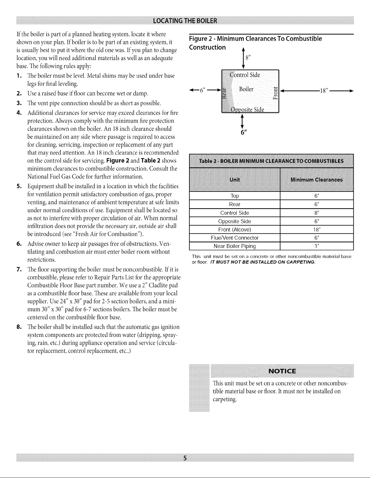
Figure 2 - Minimum Clearances To Combustible
Construction i8,,
_1_ 6 _'
Boiler _ ,_
18"
_ositeSide
6"
Top 6"
Rear 6"
Control Side 8"
Opposite Side 6"
Front (Alcove) 18"
Flue/Vent Connector 6"
Near Boiler Piping 1"
This unit must be set on a concrete or other noncombustible material base
or floor. IT MUST NOT BE INSTALLED ON CARPETING.
Thisunit must be set on a concreteor other noncombus-
tiblematerial base or floor.It must not be installed on
carpeting.
Page 6
Provisionforcombustionandventilationairmustbe
inaccordancewiththeNationalFuelGasCode,ANSI
Z223.1-latestrevision,orapplicableprovisionsofthelocal
buildingcodes.
Besuretoprovideenoughfreshairforcombustion.
Enoughairinsurespropercombustionandassuresthatno
hazardwilldevelopduetothelackofoxygen.
Youmustprovideforenoughfreshairtoassurepropercombustion.
Thefireintheboilerusesoxygen.Itmusthaveacontinuoussupply.
Theairinahousecontainsonlyenoughoxygentosupplytheburner
forashorttime.Outsideairmustenterthehousetoreplacethat
usedbytheburner.Studyfollowingexamples1and2todetermine
yourfreshairrequirements.
iiiiiiiiiiiiiiiiiiiiiiiiiiiiiiiiiiiiiiiiiiiiii_
iiiiiiiiiiiiiiiiiiiiiiiiiiiiiiiiiiiiiiiiiiiiii_
Ifyou use afireplaceor a kitchen or bathroom exhaustfan,
you should installan outside air intake. These deviceswill
rob theboiler and water heater of combustion air.
Sizing Air/Ventilation Openings
Airopenings must be sized to handle allappliances and
air movers(exhaust fans,etc.) usingthe air supply.For
air openingsinto spaces containing other appliancesin
addition to the boiler referto the NationalFuel GasCode,
ANSIZ223.1for sizing.
If NoOther GasAppliances InThe Same Space
Provide air openings intothe boiler spaceas describedin this sec-
tion and the National FuelGasCode,ANSI Z223.1.Direct exhaust
installationsrequire airfor combustion and ventilation. Directvent
installationsmay require air openings for ventilation(to prevent
overheatingof boiler controls and boiler space).
When Other GasAppliances Sharethe Same Space
For airopenings into spaces containing other appliancesin addition
to the boiler referto the NationalFuel GasCode,ANSI Z223.1for
sizing.
Page 7
EXAMPLE 1: Boiler Located In Unconfined Space
An unconfined space is defined as a space whose volume is not less than 50 cubic feet per 1,000 Btu per hour of the total input rating of all
appliances installed in that space.
If your boiler is in an open area (non-partitioned basement) in a conventional house, the air that leaks through the cracks around doors and
windows will usually be adequate to provide air for combustion. The doors should not fit tightly. Do not caulk the cracks around the win-
dows.
iiiiiiiiiiiiiiiiiiiiiiiiiiiiiiiiiiiiiiiiiiiiii_
Equipment located in buildings of tight construction shall be provided with air for combustion, ventilation, and dilution of flue
gases using the methods described in example 2 (below) or shall be specially engineered. The authority having jurisdiction must
approve specially engineered installations, a building of tight construction is defined as: 1)walls exposed to the outdoor atmo-
sphere have a continuous water vapor retarder with a rating of one perm or less with openings gasketed or sealed; and 2) openable
windows and doors which meet the air leakage requirements of the International Energy Conservation Code, Section 502.1.4; and
3) caulking or sealants are applied to areas such as joints around window and door frames, between sole plates and floors, between
wall-ceiling joints, between wall panels, at penetrations for plumbing, electrical and gas lines, and at other openings.
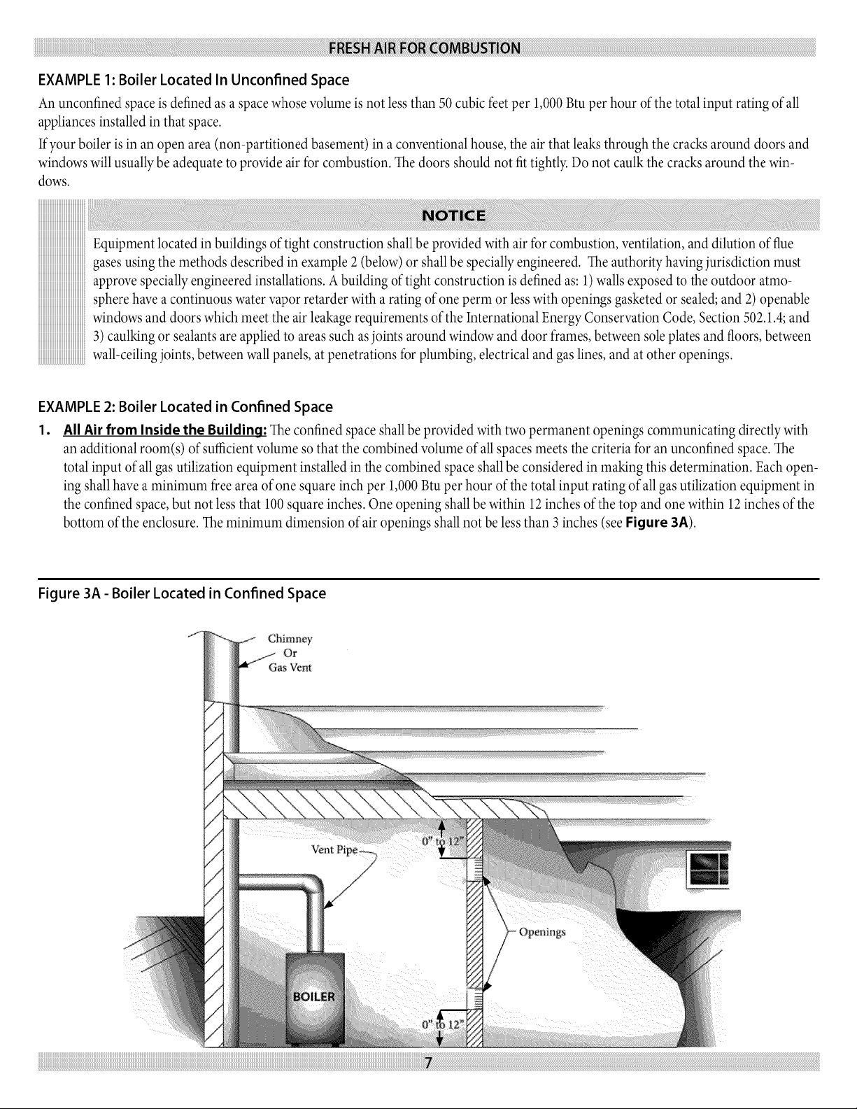
EXAMPLE 2: Boiler Located in Confined Space
1. All Air from Inside the Building: The confined space shall be provided with two permanent openings communicating directly with
an additional room(s) of sufficient volume so that the combined volume of all spaces meets the criteria for an unconfined space. The
total input of all gas utilization equipment installed in the combined space shall be considered in making this determination. Eachopen-
ing shall have a minimum free area of one square inch per 1,000 Btu per hour of the total input rating of all gas utilization equipment in
the confined space, but not less that 100 square inches. One opening shall be within 12 inches of the top and one within 12 inches of the
bottom of the enclosure. The minimum dimension of air openings shall not be less than 3 inches (see Figure 3A).
Figure 3A - Boiler Located in Confined Space
f
Chimney
Or
GasVent
Vent Pipe_
) Openings
Page 8
o
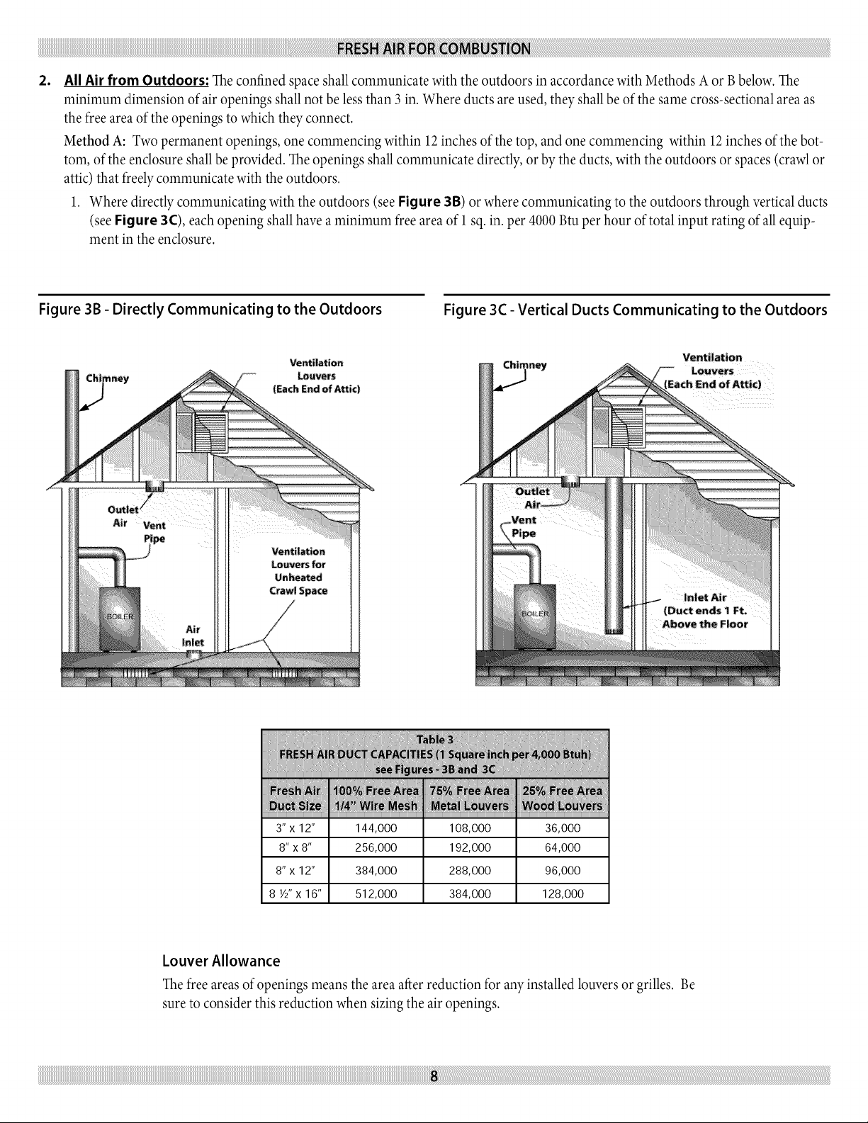
All Air from Outdoors: The confined space shall communicate with the outdoors in accordance with Methods A or Bbelow. The
minimum dimension of air openings shall not be less than 3 in. Where ducts are used, they shall be of the same cross-sectional area as
the free area of the openings to which they connect.
Method A: Two permanent openings, one commencing within 12 inches of the top, and one commencing within 12inches of the bot-
tom, of the enclosure shall be provided. The openings shall communicate directly, or by the ducts, with the outdoors or spaces (crawl or
attic) that freely communicate with the outdoors.
1. Where directly communicating with the outdoors (see Figure 3B) or where communicating to the outdoors through vertical ducts
(see Figure 3C), each opening shall have aminimum free area of 1 sq. in. per 4000 Btu per hour of total input rating of all equip-
ment in the enclosure.
Figure 3B - Directly Communicating to the Outdoors Figure 3C - Vertical Ducts Communicating to the Outdoors
Air
Pipe
3"x 12" 144,000 108,000 36,000
8"x 8" 256,000 192,000 64,000
8"x 12" 384,000 288,000 96,000
8 ½"x16" 512,000 384,000 128,000
Louver Allowance
The free areas of openings means the area after reduction for any installed louvers or grilles. Be
sure to consider this reduction when sizing the air openings.
Page 9
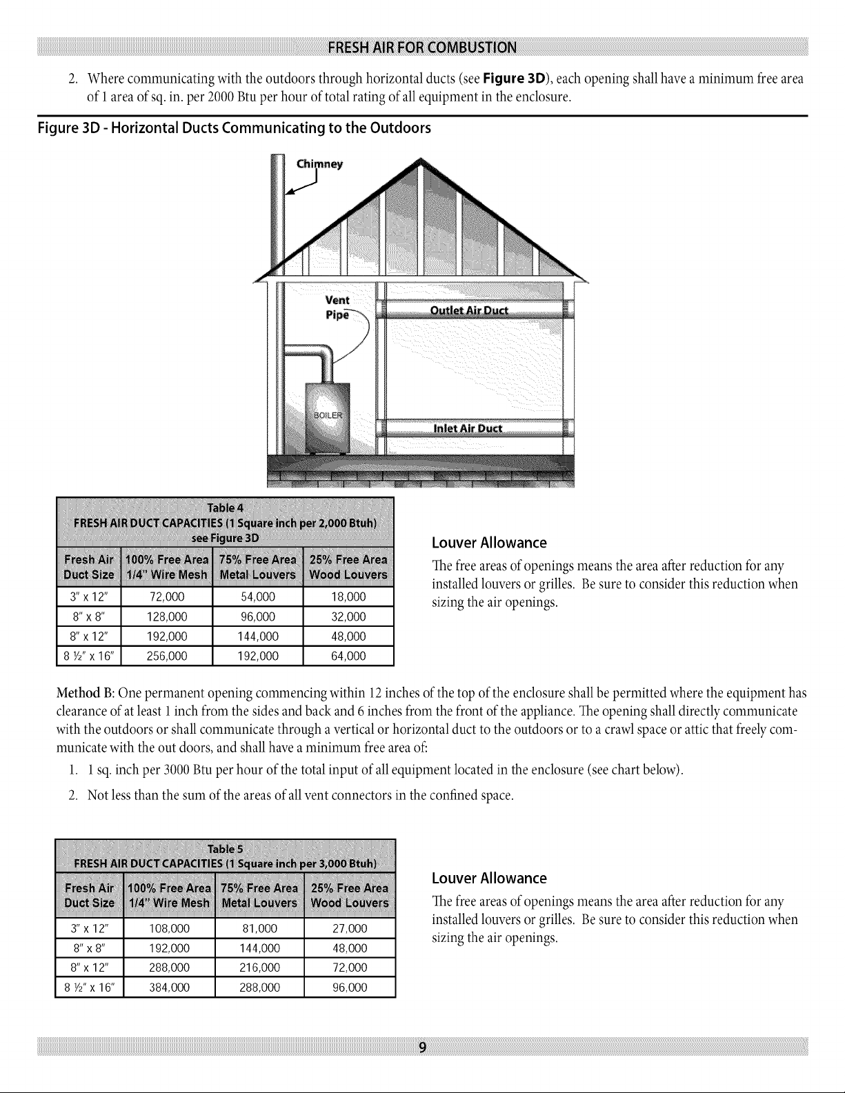
2. Wherecommunicatingwiththeoutdoorsthroughhorizontalducts(seeFigure 3D), each opening shall have a minimum free area
of 1area ofsq. in. per 2000 Btu per hour of total rating of all equipment in the enclosure.
Figure 3D - Horizontal Ducts Communicating to the Outdoors
Louver Allowance
The free areas of openings means the area after reduction for any
installed louvers or grilles. Be sure to consider this reduction when
3"x 12" 72,000 54,000 18,000
8"x 8" 128,000 96,000 32,000
8"x 12" 192,000 144,000 48,000
8 ½"x16" 256,000 192,000 64,000
sizing the air openings.
Method B:One permanent opening commencing within 12 inches of the top of the enclosure shall be permitted where the equipment has
clearance of at least 1inch from the sides and back and 6 inches from the front of the appliance. The opening shall directly communicate
with the outdoors or shall communicate through a vertical or horizontal duct to the outdoors or to a crawl space or attic that freely com-
municate with the out doors, and shall have a minimum free area off
1. 1 sq. inch per 3000 Btu per hour of the total input of all equipment located in the enclosure (see chart below).
2. Not less than the sum of the areas of all vent connectors in the confined space.
Louver Allowance
The free areas of openings means the area after reduction for any
3"x12" 108,000 81,000 27,000
8"x 8" 192,000 144,000 48,000
8"x12" 288,000 216,000 72,000
8 ½"x 16" 384,000 288,000 96,000
installed louvers or grilles. Be sure to consider this reduction when
sizing the air openings.
Page 10
To avoid burns, scalding, or water damage due to discharge of steam and/or hot water during operation, a discharge
line shall be installed to relief valve outlet connection.
The discharge line shall:
•connect to relief valve outlet and piped down to safe point of disposal.
•be of pipe size equal to or greater than that of the relief valve outlet over the entire length of discharge line;
•have no intervening shutoffvalve between safety relief valve and discharge to atmosphere (do not plug or
place any obstruction in discharge line.
iiiiiiiiiiii_iiiiiiiiiii_
•terminate freely to atmosphere where any discharge will be clearly visible and at no risk of freezing;
•allow complete drainage of the valve and the discharge line;
iiiiiiiiiiiiiiiiiiiiiiiiiiiiiiiiiiiiiiiiiiiiiii
•be independently supported and securely anchored to avoid applied stress on the relief valve;
iiiiiiiiiiiiiiiiiiiiiiiiiiiiiiiiiiiiiiiiiiiiiii
iiiiiiiiiiiiiiiiiiiiiiiiiiiiiiiiiiiiiiiiiiiiiii
iiiiiiiiiiii
Refer to local codes and appropriate ASME Boiler and Pressure Vessel Code for additional installation requirements.
1. Place boiler in the selected location (as near chimney as pos- 3.
sible). Your boiler is shipped assembled. You need only to
install the circulator, ball valves, the relief valve with a drain line
to carry any water to a drain, and the drain valve.
o
Install relief valve on 3/4" pipe nipple in tapped boiler opening.
Pipe the discharge line following guidelines in the preceding
line pipe size shall be equal or greater than that of the relief
valve outlet over the entire length of discharge line with no
intervening shutoffvalve between the safety relief valve and dis-
charge to atmosphere. Thedischarge line shall terminate with
a plain end to atmosphere where any discharge will be clearly
visible and is at no risk of freezing. The discharge line shall be
independently supported to avoid applied stress on the relief
valve. The installation shall allow complete drainage of the
relief valve and the discharge line. The discharge line shall be as
short and straight as possible and constructed of a material suit-
able for exposure to temperatures of 375° F or greater.
•be as short and straight as possible;
•terminate with plain end (not threaded);
•be constructed of material suitable for exposure to temperatures of 375° F;
•or greater.
Referto localcodes and appropriate ASMEBoilerand Pressure
VesselCode for additional installation requirements.
o
Install Drain Valveon lowerleftside ofboiler as marked.
5.
Install Temperature and Pressure Gauge into 1A,,bushing
threaded in tee furnished with supply piping See Figures 5
Refer to example shown in Figure 4. The discharge
and 6).
6,
Connect Supply and Return Lines to boiler, as shown in Fig-
ures 5 and 6. The connections may require certain additional
fittings and parts.
Page 11

Figure 4 - Relief Valve Discharge Piping
RELIEFVALVE
DISCHARGE
PIPING
Check local code_
for maximum
distance from
floor or other al-
lowable safe point
of discharge
Figure 6 - Forced Hot Water Typical Piping With Zone
Control Valve
ZONE VALVE o,
Figure 5 - Forced Hot Water Typical Piping
MAiN
T_K
Page 12

Ifyou areinstalling an entire new heating system,first install allof
yourradiation units (panels,radiators or cabinets)andthe Supply
and Return Mains - then make the connections atthe boiler.
In connecting the cold water supply to the water vane, make sure
that a clean water supply is available. When the water supply is from
a well or pump, a sand strainer should be installed at the pump.
A hot water boiler installed above radiation level must be equipped
with a low water cutoffdevice. A periodic inspection is necessary, as
is flushing of float type devices, per manufacturers specific instruc-
tions.
When the boiler is used in connection with refrigeration systems
it shall be installed so that the chilled medium is piped in parallel
with the heating boiler with appropriate vanes to prevent the chilled
medium from entering the heating boiler (Figure 7).
If the boiler is connected to heating coils located in air handling
units where they may be exposed to refrigerated air circulation, the
piping system shall be equipped with flow control valves or other
automatic means to prevent gravity circulation of the boiler water
during the cooling cycle.
Low Design Water Temperature Systems (Below 140° F)
And Large Water Content Systems:
Significant condensation may form in this boiler and/or
the venting system if the boiler is operated with return
temperatures of less than 120° E
Thiscondensation is corrosiveand can eventuallycauseseveredam-
ageto the boilerand venting system.The minimum designreturn
watertemperature toprevent this condensation in the boilerand
venting is 120°ETheminimum high limit setting is 140°E
Ifthe boileris to be usedin aheating systemwheredesign water
temperatures below 140°Faredesired (e.g.radiant floor heating),
a3-wayor 4-waymixingvane or suitablealternative is required
to prevent lowtemperature return waterfrom entering the boiler.
When using amixing vane, followthe manufacturer's installation
instructions.
If the boiler is to be connected to a system having a large water con-
tent (such as aformer gravity system), it is suggested to use bypass
piping shown in Figure 8.
Figure 7 - Piping Arrangements For Boiler When Used In
Connection With Refrigeration System
VALVESA& B_OPENFORHEATmNG;CLOSEDFORCOOLING
VALVESC& D- CLOSEDFORHEATING;OPENFORCOOUNG
TOSYSTEM
Figure 8 - Bypass Piping
ReturnFromSystem
Thermometer
Aquastat Water To System
Front
Throttling
Feed
Fi_Rro_With
Air Purger
[ Adi_stthe twoth_ttli_g valvesto maintainat leas_i20_F i:ntheboilerreLum
Page 13

iiiiiiiiiiiiiiiiiiiiiiiiiiiiiiiiiiiiiiiiiiiiii_
iiiiiiiiiiiiiiiiiiiiiiiiiiiiiiiiiiiiiiiiiiiiii_
For boilers for connection to gas vents or chimneys, vent
installations shall be in accordance with the National Fuel
Gas Code, ANSI Z223.1-latest revision and applicable
provisions of the local building codes.
CheckYour Chimney
Thisis avery important part ofyour heating system.It must be
clean,the right size,properly constructed and in GOOD CONDI-
TION.No boiler can function properly with abad chimney.
1. Uselocal codes forinstallation or National Fuel GasCode
Z223.l-latest revision.In Canada, followCSAB149.1or .2
Installation Codes.It isvery important to properly sizethe
venting systemfor induced draft appliances.Consult the Vent
SizingTables,in the National FuelGas Code ANSIZ223.l-
latest revision for correct sizinginformation. In Canada, consult
the Vent SizingTables,Amendment #1 toCSA-B149.1and .2
Installation Codes.
2. The boiler's induced draft blower has a 3" outlet. A 3" X 4"
increaser fitting is included in the parts bag. Locate the in-
creaser fitting on the outlet of the induced draft blower, and
secure gastight with a bead of the furnished silicone sealant. The
increaser fitting is required on this boiler for Category I venting,
and 4" is the minimum permissible vent diameter. This does
not imply that the vent connector is intended to be 4" diam-
eter pipe. The vent connector shall be sized according to the
appropriate venting tables in the National Fuel Gas Code or the
Canadian Installation Codes, and may be required to be larger
than 4" diameter.
The boiler installation for chimney venting is not complete
unless the Y'x 4" increaser fitting islocated and secured.
3.
Theseare highefficiencyboilers withalow stackor exhaust
temperature.
.
Ifventing into amasonry chimneywithout aliner, linethe
chimneyfrom top to bottom with either:
A. ListedType Bvent pipe
B. Listedflexiblevent liner
C. Poured ceramicliner.
5. Outside chimneysshould not be used unlessthey are (choose
one ofthe following):
A. Enclosedin a chase
B. Lined with TypeBvent pipe
C. Usea listedflexiblevent liner
D. Usea certified chimney lining system
6. The vent connector from the boiler tothe chimney should run
asdirectlyas possiblewith asfewelbowsas possible.
7. Where possible,it is recommended to common vent the water
heater andboiler. Consult the appropriate Vent SizingTablesin
either the National FuelGasCode, or the Canadian Installation
Codesfor specificrequirements ofmultiple appliance venting.
8. If the boiler isthe onlyappliance connected to the vent, Type B
vent pipe is recommended forthe vent connector.
9. Slopepipe up from boiler to chimney not lessthan 1/4"per
foot.
10. End ofvent pipe must be flushwith theinside faceof the chim-
ney flue.Use asealed-in thimble for the chimney connection.
11. The sections ofvent pipe should be fastenedwith sheetmetal
screwsto make the piping rigid. Use stovepipewires to support
the pipe from above.
12. Do not connect to fireplaceflue.
13. Do not installa damper on this boiler.
Minimum Vent Pipe Clearance
If the vent pipe must go through a crawl space, Type Bvent pipe
should be used. Where vent pipe passes through a combustible wall
or partition, use a ventilated metal thimble. The thimble should be 4
inches larger in diameter than the vent pipe.
If boiler is installed with single wall vent, it must have a 6" clear-
ance between its surface and any combustible material. A new Type
B gas vent or flexible liner must be installed in accordance with the
instructions furnished with the vent. Maintain clearances as speci-
fied for the vent pipe.
Check the vent pipe to see if it is fire-stopped where it goes through
the floor or ceiling. It should have an approved vent cap with clear-
ances from the roof as shown in Figure 9. If clearances are less
than shown in Figure 9, have the vent checked by local authorities.
For boilers for connection to gas vents or chimneys, vent installa-
tions shall be in accordance with the National Fuel Gas Code, ANSI
Z223. l-latest revision and applicable provisions of the local building
codes. In Canada, follow CSA B149.1 or .2 Installation Codes.
Vent connectors serving appliances vented by natural draft shall not
be connected into any portion of mechanical draft systems operating
under positive pressure.
Removing Existing Boiler From Common Venting System
When an existing boiler is removed from a common venting system,
the common venting system is likely to be too large for proper vent-
ing of the appliances remaining connected to it.
At the time of removal of an existing boiler, the following steps shall
be followed with each appliance remaining connected to the com-
mon venting system placed in operation, while the other appliance
remaining connected to the common venting system are not in
operation.
1. Seal any unused openings in the common venting system.
2. Visually inspect the venting system for proper size and hori-
Page 14

Figure 9 - Type B Gas Vent
Liner
Chimney
Sheet Metal
Vent System
Cleanout
CHECK YOUR CHIMNEY
This is a very important part of your heating system.
It must be clean, the right size, properly constructed
and in GOOD CONDITION. No boiler can function
properly with a bad chimney. Use local codes for instal-
lation or National Fuel Gas Code Z223. l-latest revision.
In Canada, follow CSA B149.1 or .2 Installation Codes.
It is very important to properly size the venting system
for induced draft appliances. Consult the Vent Sizing
Tables, in the National Fuel Gas Code ANSI Z223. l-
latest revision for correct sizing information. In Canada,
consult the Vent SizingTables, Amendment # 1to CSA-
B149.1 and.2 Installation Codes.
iiiiiiiiiiiiiiiiiiiiiiiiiiiiiiiiiiiiiiiiiiiiiiiiiiiiiiiiiiiiiiiiiiiiiiiiiiiiiiiiiiiiiiiiiiiiiiiiiiiiiiiiiiiiiiiiiiiiiiiiiiiiiiiiiiiiiiiiiiiiiiiiiiiiiiiiiiiiiiiiiiiiiiiiiiiiiiiiiiiiiiiiiiiiiiiiiiiiiiiiiiiiiiiiiiiiiiiiiiiiiiiiiiiiiiiiiiiiiiiiiiiiiiiiiiiiiiiiiiiiiiiiiiiiiiiiiiiiiiiiiiiiiiiiiiiiiiiiiiiiiiiiiiiiiiiiiiiiiiiiiiiiiiiiiiiiiiiiiiiiiiiiiiiiiiiiiiiiiiiiiiiiiiiiiiiiiiiiiiiiiiiiiiiiiiiiiiiiiiiiiiiiiiiiiiiiiiiiiiiiiiiiiiiiiiiiiiiiiiiiiiiiiiiiiiiiiiiiiiiiiiiiiiiiiiiiiiiiiiiiiiiiiiiiiiiiiiiiiiiiiiiiiiiiiiiiiiiiiiiiiiiiiiiiiiiiiiiiiiiiiiiiiiiiiiiiiiiiiiiiiiiiiiiiiiiiiiiiiiiiiiiiiiiiiiiiiiiiiiiiiiiiiiiiiiiiiiiiiiiiiiiiiiiiiiiiiiiiiiiiiiiiiiiiiiiiiiiiiiiiiiiiiiiiiiiiiiiiiiiiiiiiiiiiiiiiiiiiiiiiiiiiiiiiiiiiiiiiiiiiiiiiiiiiiiiiiiiiiiiiiiiiiiiiiiiiiiiiiil_i_i¸iiii_ii_ii_ii_il_il_ii_ii_ii_ii_ii_ii_ii_ii_ii_ii_ii_ii_ii_ii_ii_ii_ii_ii_ii_ii_ii_ii_ii_ii_ii_ii_ii_ii_ii_ii_ii_ii_ii_ii_ii_ii_ii_ii_ii_ii_ii_ii_ii_ii_ii_ii_ii_ii_ii_ii_ii_ii_ii_ii_ii_ii_ii_ii_ii_ii_ii_ii_ii_ii_ii_ii_ii_ii_ii_ii_ii_ii_ii_ii_ii_ii_ii_ii_ii_ii_ii_ii_ii_ii_ii_ii_ii_ii_ii_ii_ii_ii_ii_ii_ii_ii_ii_ii_ii_ii_ii_ii_ii_ii_ii_ii_ii_ii_ii_ii_ii_ii_ii_ii_ii_ii_ii_ii_ii_ii_ii_ii_ii_ii_ii_ii_ii_ii_ii_ii_ii_ii_ii_ii_ii_ii_ii_ii_ii_ii_ii_ii_ii_ii_ii_ii_ii_ii_ii_ii_ii_ii_ii_ii_ii_ii_ii_ii_ii_ii_ii_ii_ii_ii_ii_ii_ii_ii_ii_ii_ii_ii_ii_ii_ii_ii_ii_ii_ii_ii_ii_ii_ii_ii_ii_ii_ii_ii_ii_ii_ii_ii_ii_ii_ii_ii_ii_ii_ii_ii_ii_ii_ii_ii_ii_ii_ii_ii_ii_ii_ii_ii_ii_ii_ii_ii_ii_ii_ii_ii_ii_ii_ii_ii_ii_ii_ii_ii_ii_ii_ii_ii_ii_ii_ii_ii_ii_ii_ii_ii_ii_ii_ii_ii_ii_ii_ii_ii_ii_ii_ii_ii_ii_ii_ii_ii_ii_ii_ii_ii_ii_ii_ii_ii_ii_ii_ii_ii_ii_ii_ii_ii_ii_ii_ii_ii_ii_ii_ii_ii_ii_ii_ii_ii_ii_ii_ii_ii_ii_ii_ii_ii_ii_ii_ii_ii_ii_ii_ii_ii_ii_ii_ii_ii_ii_ii_ii_ii_ii_ii_ii_ii_ii_ii_ii_ii_ii_ii_ii_ii_ii_ii_ii_ii_ii_ii_ii_ii_ii_ii_ii_ii_ii_ii_ii_ii_ii_ii_ii_ii_ii_ii_ii_ii_ii_ii_ii_ii_ii_ii_ii_ii_ii_ii_ii_ii_ii_ii_ii_ii_ii_ii_ii_ii_ii_i_i_i
Page 15

zontal pitch and determine there is no blockage or restriction,
leakage, corrosion and other deficiencies which could cause an
unsafe condition.
3,
Insofar asispractical, closeallbuilding doors and windows and
alldoors between the spacein which the appliancesremaining
connected to the common venting systemare locatedand other
spacesof the building. Turn on clothesdryers and any appli-
ancenot connected to the common venting system.Turn on
anyexhaust fans,such as range hoods and bathroom exhausts,
so theywill operate at maximum speed. Closefireplacedamp-
ers.
4. Place in operation the appliance being inspected. Follow the
lighting instructions. Adjust thermostat so appliance will operate
continuously.
5. Test for spillage at the hood relief opening after 5minutes of
main burner operation.
G. After it has been determined that each appliance remaining con-
nected tothe commonventingsystemproperlyventswhentested
asoutlinedabove,returndoors,windows,exhaustfans,fireplace
dampers andany other gas-burningapplianceto their previous
conditionsof use.
,
Anyimproper operation of the common venting systemshould
be corrected so the installationconforms with the National
FuelGas Code, ANSIZ223.l-latest revision.When resizing any
portion ofthe common ventingsystem,the common venting
systemshould be resizedto approach the minimum sizeas
determined usingthe appropriate tables in the National Fuel
GasCode,ANSIZ223.l-latest revision.In Canada, followCSA
B149.1or.2 Installation Codes.
NOTE:It is recommended that existinggasvents be
checkedto be sure theymeet localcodes.
Page 16

INDUCED DRAFT HIGH EFFICIENCY BOILERS
Maximum Horizontal Vent Length ForStainlessSteelVentPipe - 30'
PlusOne 90° ElbowPlusVent Terminal.
Minimum Horizontal VentLength- 2' PlusOne 90° ElbowVent
Termination.
Additional elbowsare equivalent to 6 feetof straightpipe for 4" di-
ameter 90° elbowor 3 feetof straight pipefor 3"diameter 90°elbow.
2,3,4, 5,Section Boilersuse 3"vent pipe;for 6, 7 SectionBoilersuse
4"vent pipe.
Figure 10 - Induced Draft High Efficiency boilers
Optional Termination Fitting
T Jemlund S_deWall Vent Hood
VHolo3"for 2, 3, 4& 5 Section Boilers
VH-I_4" for 6 & 7 Section _i|ers
CHOICE OF VENT PIPE MATERIAL
1. U.L. ListedZ-FlexZ-VentStainlessSteelVentPipe.
2. U.L.ListedHeat-Fab Saf-T-VentStainless SteelVent Pipe.
3. U.L. ListedFlex-LStar-34StainlessSteelVentPipe.
4. U.L. ListedProTechSystemsFasNSealStainlessSteelVent Pipe.
Termination Fitting
_° Elbow, pointing down, same matetiai and
pipe size as venting systems equtped with
screen (Min, I/4" Mesh) to keep birds outs
Fot a combustib|e wa|l, use a thimb|e_ Select as
fo|iows:
Vent Pipe: Z-Vent, SafoT_Vent,Star 34
_tmble: Simpson Duravent Thimb|e --
# 3G_¢_,/T(3% # 4GV_t#T (4")
Vent Pt_: FasNSeal
Thimble: FasNSea| Wal| Thimble
#FSWT03-3'; FSWT04-4 _'
PRchDown Toward
Outside 1i4" Per Foot
Pitch Down Towa_
Outside 1/4" Per Foot
_vel
Page 17

1,
Theseboilers maybe vented horizontally as shown in
Figure 10.Thevent pipe is pitched down from the boiler to
thevent termination. Do not connect other appliances tothis
vent.
,
Vent Pipe Material:
A. ULListedZ-FlexZ-Vent stainlesssteelvent pipe from
boilerto vent termination,
-or-
B. ULListedHeat-FabSaf-T-Vent stainless steelvent pipe
fromboiler to vent termination,
-or-
C. UL ListedFlex-LStaR-34stainless steelvent pipe from
boilerto vent termination,
6,
Vent Termination Fitting: For allvent pipe materials,you may
useeither:
A. A 90° elbowpointing down, fittedwith aminimum 114"
mesh screen to keepout rodents and birds. Theelbow shall
be ofthe same material and size as ventpipe. The elbow
exit should be at least 6" awayfrom exterior wall asshown
in Figure 10.
-0r-
B.
Tjernlund VH-1Seriessidewall vent hood. For 2,3,4, 5
sectionboilers use VH-1-3",For 6, 7section boilers use
VH-1-4".
7. Vent PipeTermination Location (Figure 10):
-or-
D. ULListedProTech FasNSealstainlesssteelvent pipe from
boilerto vent termination.
3,
Clearanceto CombustibleMaterials: Forstainless steelvent
pipemaintain 6" minimum airspaceclearanceto combustible
materials.
,
Vent Pipe Size:
A. 2, 3, 4 and 5 section boilers use 3" vent pipe connected
directly to the outlet of the induced draft blower.
B.
6 and 7 sectionboilers use4" ventpipe, starting with a3"
to 4"stainless steelvent pipe transition that is connected
directlyto the outlet of the induced draft blower.Do not
use3" ventpipe on 6or 7 sectionboilers.
5,
Vent Pipe Length:
A. For stainlesssteelvent pipe,the maximum horizontal vent
length is 30feet plus one 90°elbowplus termination fitting.
B.
Minimum horizontal vent length forall ventmaterials is 2
feetplus one 90° elbowplus termination fitting.
C.
For additional elbowsreduce the maximum vent length as
shown:
•3" - 90° elbow - reduce vent length 3 feet per each 3" elbow
•4" - 90° elbow - reduce vent length 6 feet per each 4" elbow
a.
When venting through combustible walls, combustible
clearancesmust be considered. TheVH-1 Sidewallvent
hood provides both the outside vent termination and a
double wallpipe for passing through a combustiblewall
up to 8"thick (VH-1-4")or 9" thick (VH-1-3").Thehole
in thewall must be 61_'' square for 3"vent pipe and 7 1/2"
square for 4" vent pipe, in order to insert theVH-1 side
wallvent hood. TheVH-1may alsobeused in noncombus-
tible walls.
B.
Ifthe 90° elbow isthe termination fittingof choice,then
the singlewallpipe will be passingthrough the sidewall.
For combustiblewalls, a ULlisted thimble shall be used
where the singlewallpipe passes through the wall.For
combustiblewalls usingZ-Vent, Saf-T-Vent,or StaR-34
vent pipe, usethe following:
• 3" vent pipe - use Simpson's Duravent 3" thimble
•4" vent pipe -use Simpson's Duravent4" thimble. Maxi-
mum wallthickness with this thimble is 7inches.
For combustiblewallsusing ProTechFasNSealwhere the singlewall
vent pipe must pass through the sidewall,a ULListedFasNSealwall
thimble shallbe used.
Thethimble isadjustable for differentwall thickness,with amaxi-
mum wallthickness of 7 inches.Sealthe thimble along the outside
edgeof the platewith caulkor siliconeand fasten to the wallwith
screwsor nails.
Example: 6 section boiler has 3 elbows plus the termination fitting.
This means 2 additional 4" elbows will be used, at 6 feet per elbow.
This is equivalent to 12 feet of pipe (2 x 6 =12), therefore maximum
vent length is now 18 feet (30 -12 =18).
C. For singlewallpipe through non-combustible walls, the
hole through the wallneed onlybe large enough to main-
tain the pitch of thevent pipe, and provide proper seal-
ing.A thimble isnot required for singlewall pipe passing
through noncombustible walls.
D. Theventing systemshall terminate at least 3feet above
Page 18

Figure 11 - Horizontal Venting Clearances
NOTE: _ THERE IS A POTENTIAL POR EXCES:S_VE WINDS, SPECIAL
CONSIDERATION _NOULD BE GIVEN TO LOCATE THE VENT TERMINATION
AWAY FROM THE WINDWARD Si:DE OR THE BUILD_NG,
ing system shall terminate at least 4 feet below, 4 feet
horizontally from, or 1 foot above any door, window,
or gravity air inlet into any building. The bottom of
the vent shall be located at least 12 inches above grade.
Termination of the vent shall be not less than 7 feet above
an adjacent public walkway. The vent terminal shall not be
installed closer than 3 feet from the inside corner of an L
shaped structure. Termination of the vent should be kept
at least 3 feet away from vegetation. The venting system
shall terminate at least 4 feet horizontally from, and in no
case above or below, unless a 4 foot horizontal distance is
maintained, from electric meters, gas meters, regulators,
and relief equipment. (See Figure 11)
E,
The venting system shall terminate at least 4 feet below any
eve, soffit, or roof overhang.
F. The venting system shall not terminate underneath any
deck, patio, or similar structure.
G. Put vent on awall away from the prevailing winter wind.
LOCATE VENT CAP TO ALLOW
_2" (3_ CM) MIN ABOVE: ORADE
Locate or guard the vent to prevent accidental contact with
people or pets.
H,
Terminate the vent above normal snow-line. Avoid loca-
tions where snow may drift and block the vent. Ice or snow
may cause the boiler to shut down if the vent becomes
obstructed.
Under certain conditions, flue gas will condense, forming
moisture. In such cases, steps should be taken to prevent
building materials at the vent terminal from being dam-
aged by exhaust of flue gas.
8_
Joining and Sealing the Vent Pipe:
The vent pipe needs to be both watertight and gastight. Seal all
joints and seams as follows:
A. For Z-Flex Z-Vent stainless steel vent pipe use a high tem-
perature silicone sealant rated for 550°F. The outside of the
male end and inside of the female end of the pipe must be
cleaned with brake cleaner before applying silicone bead.
Page 19

For 3"vent pipe runs beginwith the male endof the vent
pipeover the boilersinduced draft bloweroutlet. For 4"
ventpipe runs begin with a 6" lengthof 3"Z-Vent over the
boiler's induced draft blower outlet, to which an evenbead
ofhigh temperature silicone sealantshouldbe applied.
Thenconnect the 3" Z-Ventto a Z-Vent 3"to 4"reducer.
Thencontinue the 4"Z-Vent piperun byconnecting the
4" male end of the Z-Ventto the reducer. (A locking band
maybe used around this joint for additional support.) Then
followingthe sealinginstructions, push the4" male end of
the Z-Vent overthe 4" increaserfitting. When using the
Tjernlund VH-1 vent hood, the femaleend (flaredend) of
thevent pipe willbe connected to the termination hood.
Themale endof thevent hood must be crimped before
pushing the Z-Vent over thevent hood's connecting pipe.
Beforethe pipes are joined, applya ¼" bead of siliconeone
inch from the endof the male end. Then pushthe pipes
together asfar asthey willgo makingsure any seamsare
alignedand oriented upward. Now apply another beadof
silicone around this joint and smooth out. Then use a Z-
Flexlockingband around the center of the joint.
1. Apply the high temperature silicone approximatelyone
inchfrom the end, around the male end ofthe pipe in
an even ¼" bead.
,
Pipescan now be pushed together asfar as they will
go. Theseams onpipe should be alignedand oriented
upward in allhorizontal appliances. Applyanother bead
of siliconearound this joint and smooth out.
,
Slidelockingband overcenter of joint and tighten gear
clamps.Makesure locking band is centered onjoint.
,
Checkalljoints and seams for gastightness.
5.
Horizontal ventingshall haveaslope notless than ¼"
(6.4mm) every12inches (305mm)downward away
from the boilerto preventcollectionof condensate
throughout the assembly.
,
Allowthe sealant to cure for 24hours before operating
the appliance.
B,
For Heat-Fab Saf-T-Ventstainlesssteelvent pipe use
ahigh temperature siliconesealantrated for 550°F
Theoutside ofthe male end and inside ofthe female
end ofthe pipe must becleanedbefore applyingthe
siliconebead. For 3"vent pipe runs, the male endof
thevent pipe which goes overthe outlet of theboiler's
induced draftblower must be crimped. Thevent pipe
should be crimpedas minimal aspossible to provide
atight fit overthe outlet. After crimping is completed
followthe instructions forapplying siliconesealant.
For 4"vent pipe runs, begin with a Saf-T-Vent3"to 4" in-
creaserfittingoverthe boiler'sinduced draft bloweroutlet,
to which an even bead of high temperature siliconesealant
shouldbe applied. Thencontinue the 4" Saf-T-Ventpipe
run by connecting the 4" male end of the Saf-T-Ventto the
increaser.(Alockingband maybe usedaround thisjoint
for additional support.) Thevent flowmust be in the direc-
tion indicatedon the ventpipe. When usingthe Tjernlund
VH-1 vent hood, the femaleend (flared end) ofthe vent
pipe willbeconnected to the termination hood. Applyhigh
temperature silicone in an even ¼"bead approximately¼"
to 3/8"from the end of the venthood's connecting vent pipe.
Also,run asimilar sizebead ofsilicone sealantdown the
seamweldofthe vent pipe. Then push the femaleend over
the vent hood'sconnecting vent pipe.
1. Apply thehigh temperature siliconearound the male
end ofthe pipe (without the tabs) in an even ¼"bead.
Siliconebead should be approximately¼"to 3/8"from
the end ofthe male end. Also,run a similarsizebead of
silicone sealantdown the seam weld at the end of each
joint.
,
Pipes cannow be pushed together asfar as theywill
go. Theseams onthe vent pipe should be alignedand
oriented upward in allhorizontal appliances.With a
moistened fingeror fiat tool, spreadany sealant that
squeezesout around the circumference of the joint.
,
Attach the sectionstogether with the locking rings and
tabs (exceptat the bloweroutlet where no locking ring
exists.) Inspectthe joint to ensurethat fluegaseswill
not leak.If necessaryapplyadditional sealantaround
thejoint.
,
Horizontal venting shallhave a slopenot lessthan ¼"
(6.4mm) every 12inches (305mm) downwardaway
from the boilerto prevent collectionof condensate
throughout the assembly.
5. Allowthe sealantto cure for 24 hours beforeoperating
the appliance.
C,
For Flex-LStaR-34stainless steelvent pipe use ahigh
temperature siliconesealant rated for 550°F.Beforeapply-
ing silicone,the outside of themale end and inside ofthe
femaleend of the pipe must be cleaned using acleaner,
suchas methyl ethyl ketone (MEK)or naptha. For 3"
vent pipe runs, beginwith the male endof the vent pipe
over the boiler'sinduced draftbloweroutlet. For 4"vent
pipe runs begin with aStaR-34 3"to 4"increaser fitting
over the boiler'sinduced draftbloweroutlet. For both
3" and 4"vent pipe runs,apply a bead ofsilicone seal-
ant around the blower outlet and around the inside of
the male end ofvent pipe going overthe blower's outlet.
When usingthe Tjernlund VH-1 vent hood,the
femaleend (flaredend) ofthe vent pipe
willbe connected to the termination hood.
Page 20

Applyhigh temperature siliconein an even ¼"bead ap-
proximately 1/4"from the end ofthe vent hood's connecting
ventpipe. Also,run a similar sizebead of siliconesealant
down the seam weldof the vent pipe. Then push the female
end over thevent hood's connecting vent pipe. Now fillin
the channel inlet with siliconesealant.Do not try to insert
thejoiner band, instead fastenthe vent pipe tothe vent
hood's pipe with a steelgear clamp.
1. Apply the high temperature silicone around the male
endof the pipe in an even ¼" bead. Siliconebead
shouldbe approximately ¼" fromthe end of the male
end. Also,run a similarsize bead of siliconesealant
down the seamweld at the end of each joint.
2. The seams on the vent pipe should be alignedand ori-
ented upwardin allhorizontal vent pipe runs.
3. Insert the maleend ofone into thefemaleend of the
other. Push the pipe together sothe female end rests up
againstthe stop bead of themale end.
.
Insert a StaR-Joiner Band into the inlet of the beaded
channel. Feed the Joiner Band in so it makes its way
around the pipe, back to the channel inlet and it over-
laps itself by about 1/2".
.
Cutthe excessJoiner Band soit lays fiatin the beaded
channel.Fillthe inlet ofthe beaded channel withhigh
temperature silicone.Smooth outthe siliconeover the
channel inlet and the siliconebetween the female end
and thestop bead of the male end.
.
Horizontal ventingshall haveaslope notless than ¼"
(6.4mm) every12inches (305mm)downward away
from the boilerto preventcollectionof condensate
throughout the assembly.
7. Allowthe sealant to cure for 24hours before operating
the appliance.
D.
For ProTechSystemsFasNSealstainlesssteel vent pipe
no cleaningfluid isrequired. For 3" vent pipe runs on 2,
3,4 and 5 section boilers,begin bylocating the FasNSeal
AmetekAdapter overthe boiler's induced draft blower.
Continue the vent piperun with 3" FasNSealvent pipe.
For 6and 7 section boilers, begin by locatingthe FasNSeal
AmetekAdapter over the boiler'sinduced draft blower.
Thenconnect a FasNSeal3"to 4" increaserto the 3"
adapter outlet.Continue thevent piperun with 4"FasNSeal
ventpipe. Other than the Ametek Adapter and increaser
fitting,DO NOT use 3"vent pipe on 6or 7 sectionboilers.
FasNSealventpipe isjoined and sealedby the useof an
internal sealinggasketand alocking band on the female
end ofeachvent pipe.Allcomponents should be examined
for possibleshippingdamage prior to installation. Align
allvent pipe seamsand orient upward in allhorizontal
applications.Adjustablevent lengths areavailablefor4"
diameter vent piping.For 3" diameter vent piping, square
cutmale end at the desired length. For2, 3,4 and 5 section
boilers usingthe VH-1-3" vent hood, connect the FasNSeal
Ventto the VH-1-3"vent hood using FasNSealAdapter
#FSC-DUN-3.Thisadapter has no internal sealinggasket.
Toattach the adapter to the vent hood, crimp the 3"vent
hood pipe,apply a 1/4"bead ofhigh temperature silicone
sealantaround the outside of the venthood's crimped
connecting pipeand asimilar bead of high temperature
siliconearound theinside ofthe FasNSealadapter. After
pressing thetwo pipestogether and tightening the locking
band, finish creatinga complete sealby fillingthe FasNSeal
adapter'snotched holewith hightemperature silicone.
For 6 and 7 sectionboilers using the VH-1- 4"vent hood,
an adapter isnot required. The 4" FasNSealventpipe con-
nects directlyto the VH-1-4" venthood, and is joined and
sealedby the internal gasketand lockingband.
Tojoin and seal the FasNSealvent pipe:
1. Insert maleend into female section.
2. Push the units together as faras possible.
3. Firmly tighten locking band with anut driver.
4. DO NOT penetrate theFasNSealvent pipe with fasten-
ers.
.
Horizontal venting shallhave a slopeof not less than
¼"(6.4mm) every12inches (305mm)downward away
from the boilerto prevent the collectionof condensate
throughout the assembly.
o
Support Spacing:
Donot restrict thermal expansion movement of the vent. The
vent pipe must expand and contract freely with temperature
change.Eachrun ofventpiping shallbe supported asfollows:
A. Z-Flexstainlesssteel ventpiping requires a loosefitting
metal strap or similar support at eachjoint at a maximum
of 4 feetbetween supports.
B. Heat-Fab stainlesssteelvent piping requiresa support for
every6 feet ofhorizontal piping run. Thesupport must be
securedusing at least#10fastenersto asolid material (solid
masonry or wood framing or blocking.)Do not fastento
drywall sheathingusing hollowwall anchors. Each sup-
port willbe 11/2inch lowerthan the previous support when
spaced6feet apart.
C. Flex-Lstainlesssteelvent piping requires aloose fitting
metal strap or similar support at eachjoint at a maximum
of 4 feetbetween supports.
D. ProTech stainlesssteelvent piping requires one loose fit-
ting FasNSealsupport strap for every6' ofhorizontal vent.
Page 21

10. If the horizontal vent must go through a crawl space or other
unheated space, the cool temperatures will likely cause the flue
gases to continuously condense inside the vent pipe. Do not
insulate the vent pipe. It must be visible for monthly inspec-
tion. Insure that the vent pipe is properly pitched away from
the boiler, with no low spots, sothat condensate in the vent will
drain away from the boiler. An insulated enclosure or chase,
with access for inspection and servicing of the vent, may be
required to prevent freezing of liquid condensate. Consult the
vent pipe manufacturer's instructions for specific guidelines.
11. At the beginning of each heating season and monthly during
the heating season, check all vent pipes and the vent terminal
to make sure there are no obstructions. Periodically clean the
screen in the vent terminal.
Horizontal ventingwith apower venter is an alternatemethod of
sidewallventing. Thisboiler is CSAlisted for sidewallventing with
standard singlewallgalvanized or TypeBvent pipe when usingthe
followingpower venterkits, which werespecificallysizedfor these
boilers:
2,3, 4,5 SWG-4D
6,7 SWG-SD
Somepossiblereasons for using apower venterfor sidewallventing:
1. May be preferred by localcodes.
2. Need avent pipingrun beyond 30' (butnot more than 50').
3. The boiler installation site experiencesgusting or high winds.A
power venter canhelp prevent the boiler from short cyclingdue
to gusting or high winds byproviding ventexhaust pressures
greater than the boiler'sinduced draft blower alone.
4. When installersor homeowners prefera negativepressure vent
systeminstead of a positive pressure vent system.
5. May bemore costeffectivethan stainlesssteel
venting,particularly at longer vent lengths.
TheFieldControls powervent kit includeseither a SWG-II-
4HD or SWG-II-5power venter,a MG-1 4" barometric draft
controller,and the CK-43Dcontrols kit.
Confirm that installingapower venter isan option allowedby local
codes.Followthe specificpowerventer installation instructions
issuedwith the power venter kits. Although the powerventer is
equippedwith itsownfan, the fanon the boiler remains in place and
isunaltered whena power venter isused.
When sidewallventing, fluegasesmust be vented to apoint in rela-
tion tothe prevailingwind so that they may freelydisperse without
being blown backat the building causingdiscoloration, orinto the
building through doors or windows causingodors. Also,under cer-
tain conditions fluegaseswill condense, forming moisture. In such
cases,steps should be taken to preventbuilding materialsat the vent
terminal frombeing damaged by the exhaustedfluegas.
When installing singlewall galvanizedvent pipe forpower venting
followthe specificpower venter installation instructions for layout,
location ofthe barometric draft control and termination connec-
tions.
When joining and sealingthe singlewall galvanizedor Type Bvent
piping, use RTVsilicone sealantwith aminimum temperature rating
of 400°EFor 3"vent pipe runs, begin with the female end of the vent
pipe overthe boiler'sinduced draft bloweroutlet. For4" ventpipe
runs begin with the galvanized3" to 4" increaser fitting (included in
the boiler'sparts bag)over the induced draft bloweroutlet. Thenfol-
low by placingthefemale end of the 4"vent pipe overthe increaser
fitting.
When joining piecesofsinglewall galvanizedvent pipe,a substan-
tial bead ofsiliconeshould be used atthe joint to insure aleakproof
connection.
Page 22

Connecting The Gas Piping
Refer to Figure 12 for the general layout at the boiler. It shows the
basic fittings you will need. The gas line enters the boiler from the
right side. Flexible gas connectors must never breach any boiler
openings.
Figure 12 - GAS PIPING AT BOILER
Never use a match or open flame to test for leaks.
9. Two-stage regulation should be used by the propane installer.
10. Propane gas piping should be checked out by the propane
installer.
Checking The Gas Piping
Upon completion of piping, check right away for gas leaks. Open
the manual shut-offvalve. Test for leaks by applying soap suds (or
a liquid detergent) to each joint. Bubbles forming indicate a leak.
CORRECTEVENTHE SMALLEST LEAK AT ONCE.
Manifold
Automatic Ground
GasValve, Joint
Check Gas Supply
The gas pipe to your boiler must be the correct size for the length
of the run and for the total BTU per hour input of all gas utilization
equipment connected to it. See Gas Table 8 for the proper size.
Be sure your gas line complies with local codes and gas company
requirements.
Tmp
Floor Line
.iiiiiiiiiiiiiiiiiiiiiiiiiiiiiiiiiiiiiiiiiiiiiiiiiiiiiiiiiiiiiiiiiiiiiiiiiiiiiiiiiiiiiiiiiiiiiiiiiiiiiiiiiiiiiiiiiiiiiiiiiiiiiiiiiiiiiiiiiiiiiiiiiiii
20 92,000 190,000 350,000 625,000
40 63,000 130,000 245,000 445,000
MIN. SUPPLY 5" w.c. 11" w.c.
MAX. SUPPLY 14" w.c. 14" w.c.
MANIFOLD 3.5" w.c. 10" w.c.
The following rules apply:
1. Use only those piping materials and joining methods listed
as acceptable by the authority having jurisdiction, or in the
absence of such requirements, by the National Fuel Gas Code,
ANSI Z223.1- latest revision. In Canada, follow the CSA B149.1
and .2 Installation Codes for Gas Burning Appliances and
Equipment.
2. All pipe compound must be resistant to liquefied petroleum gas.
3. Install ground joint union in gas supply line between shut-off
vane and boiler controls.
4. Install a sediment trap upstream of gas controls.
5. Use two pipe wrenches when making the connection to the gas
vane to keep it from turning.
6. Install manual shut-offvaNe in vertical pipe about 5 feet above
floor.
7. Tighten alljoints securely.
8. Propane gas connections should only bemade bya licensed
propane installer.
60 50,000 105,000 195,000 365,000
216,000 189,000 393,000
145,000 129,000 267,000
121,000 103,000 217,000
The length of pipe or tubing should be measured j?om the gas meter or propane
second stage regulatoc
The boiler and its individual shutoffvaNe must be disconnected
from the gas supply piping system during any pressure testing of that
system at test pressures in excess of 1/2Psig (3.5 kPa).
The boiler must be isolated from the gas supply piping system by
closing its individual manual shutoff vane during any pressure test-
ing of the gas supply piping system at test pressures equal to or less
than 1/2Psig (3.5 kPa).
Page 23

All electrical work must conform to local codes as well as the Na-
tional Electrical Code, ANSI/NFPA-70, latest revision. In Canada,
electrical wiring shall comply with the Canadian Electrical Code,
CSA-C22.1.
iiiiiiiiiiiiiiiiiiiiiiiiiiiiiiiiiiiiiiiiiiiiiiiTurn offelectricpower atfuseboxbefore makinganyline
iiiiiiiiiiiiiiiiiiiiiiiiiiiiiiiiiiiiiiiiiiiiiiivoltageconnections. Followlocalelectricalcodes.
Electric Power Supply
Run a separate 120volt circuit from a separate over current protec-
tive device in the electrical service entrance panel. This should be a
15 ampere circuit. Locate a shut-off switch at the boiler. It must be
turned offduring any maintenance. Connect 120 volt power supply
to aquastat terminals L1 (HOT) and L2.
The boiler, when installed, must be electrically grounded in accor-
dance with the requirements of the authority having jurisdiction or,
in the absence of such requirements, with the National Electrical
Code, ANSI/NFPA No. 70 - latest revision. Run a 14gauge or heavier
copper wire from the boiler to a grounded connection in the service
panel or a properly driven and electrically grounded ground rod.
iiiiiiiiiiiiiiiiiiiiiiiiiiiiiiiiiiiiiiiiiiiiii
iiiiiiiiiiiiiiiiiiiiiiiiiiiiiiiiiiiiiiiiiiiiii
iiiiiiiiiiiiiiiiiiiiiiiiiiiiiiiiiiiiiiiiiiiiii
iiiiiiiiiiiiiiiiiiiiiiiiiiiiiiiiiiiiiiiiiiiiii
iiiiiiiiiiiiiiiiiiiiiiiiiiiiiiiiiiiiiiiiiiiiii
Label allwires prior to disconnection when servicing
controls. Wiring errors can cause improper and dangerous
operation. Verify proper operation after servicing.
Install Your Thermostat
The thermostat location has an important effect on the operation of
your boiler system. BE SURE TO FOLLOW THE INSTRUCTIONS
INCLUDED WITH YOUR THERMOSTAT. Locate the thermo-
stat about five feet (5') above the floor on an inside wall. It may be
mounted directly on the wall or on a vertically mounted outlet box.
It should be sensing average room temperature.
Behinddoors
Corners&
alcoves
Concealed pipes
Fireplace
TV sets
Radios
Lamps
Direct sunlight
Kitchens
Concealed pipes
or ducts
Stairwells-drafts
Doors- drafts
Unheated room on
other side of wall
Sequence of Operation - Refer to Figure 13
1. Thermostat calls for heat, powering the 1Krelay coil and closing
contacts 1K1and 1K2.
2. Circulator pump ispowered through terminals C1and C2.
3. Induced draft blower and transformer primary arepowered
through terminals B1and B2.
4. When blowergets up to speed andblower suction pressure
reaches pressure switchset point, pressure switchcontacts close
sending 24 voltsto intermittent pilot control from transformer
secondary.
5. Pilot gasvalve opens and spark initiates to light pilot burner.
6. When pilotflame isproven, sparkdrops out.
7. Main gasvalveopens and pilot burner ignites main burners.
Setheat anticipator at .2amps. The 24 voltthermostat connects
to aquastat terminals T and T.
8. If boiler water temperature reaches high limit setpoint, high
limit contacts B-Ropen, cutting powerto blower and intermit-
tent pilot control. Burnersextinguishand blower stops.Circula-
tor pump continues to run aslong asthe thermostat continues
to call for heat. When boilerwater temperature drops pastthe
high limit set point and through the differential,high limit
contacts B-Rclose,repeating steps3-7.
9. If venting systembecomesblocked, blower suction pressurewill
drop belowthe pressure switchset point, opening the pressure
switch contacts and cutting power to the intermittent pilot con-
trol. Burners willextinguish, butblower willremain powered
aslong asthe thermostat continuesto callfor heat. Ifventing
systemclears,steps 4-7will repeat.
10. Thermostat is satisfied,ending callfor heat. Relaycoil 1Kisde-
energized,opening 1K1and 1K2contacts. Burners extinguish.
Blowerand circulator pump stop.
Page 24

Figure #13 -Intermittent Ignition
120/60/1
POWER SUPPLY
NEUT 24V
HOT_ I THERMOSTAT
,Olw7:DISCONNEC 1
;1)/L. q <T_
\_>' _'/ \/
-!_ L8148A
AQUASTAT G
LINE VOLTAGE WIRING
LOW VOLTAGE WIRING
LOW VOLTAGE FIELD WIRING
B BLACK
BT BLACK WITH TRACER
W WHITE
G GREEN
R RED
BL BLUE
INDUCER
DRAFT
/
AT 140C TRANSFORMER
7
B
B
CIRCULATOR
HOT
B
FUSED
fll_ +DISCONNECT
i ,
1K1
?_ HIGHLIMIT
B_ B
l
INTERMITTENT PILOT CONTROL
> -_s-2_ l
>5> >_ z_Z_ I
I I
_(_ TBKTBKTBT_Bk--TOPILOT
/// / / / _" BURNER
PRESSURE ROLLOUT/// 'Ln_in
SWITCH SWITCH // W _.- GAS VALVE
/VR8204A/VRS,04M
170/60/1P?WERSUPPLY
120 V PRIMARY
[ 24ZVrSEC%NDARY _IK
.) \. _/ -
24 V THERMOSTAT O
II
1K2
¥_L31
PRESSURE ROLLOUT
SWITCH SWITCH
B _ w
G
'\S
DRAFT INDUCER
120V PRIMARY
\)_/,),..J
24 V SECONDARY
CIRCULATOR
AT 140C TRANSFORMER
w
INTERMITTENT
PILOT CONTROL
iiiiiiiiiiiiiiiiiiiiiiiiiiiiiiii
iiiiiiiiiiiiiiiiiiiiiiiiiiiiiiii
NEUT
W
(LL"i
\l j'
1/c2
\j'
TO GAS
VALVE
iiiiiiiiiiiiiiiiiiiiiiiiiiiiiiiiiiiiiiiiiiiiiiiiiiiiiiiiiiiiiiiiiiii!Ifanyoftheoriginalwireassuppliedwiththisappliance
must be replaced,it must be replacedwith type 105° C
thermoplastic wireor its equivalent.
NOTE:Thecirculatorharness isfactorywired to the
aquastat.Thisharness needs to beconnected to the circu-
latorin thefield.
Page 25

Relief Valve
Youmust havea reliefvalve on your boiler.Water expands asit is
heated. Ifthere is no placefor thewater to expand into,waterpres-
surewill build up insidethe boiler and system. Should this happen,
the ReliefValvewillautomaticallyopen ata pre-determined pres-
sure. Thiswillrelievethe strain on the boilerand system.Run apipe
from thereliefvalveoutlet (pipemust be samesizeasoutlet and the
open end must not be threaded) to anopen drain, tub or sink,or
other suitabledrainagepoint not subject tofreezing. Failure to do so
maycausewater damageor injuryshould reliefvalverelease.
Expansion Tank
In aproperly assembledsystem, the expanding water flowsinto an
ExpansionTank.This tank should be ofthe correct size.
Thetank ispartially filledwith air.Asthe water expandsit compress-
esthe air in the tankto form an airpressure cushion. This"spring-
like"cushion servesto maintain correct operating water pressure
regardlessof watertemperature. Thisassuresa "fullmeasure"ofwa-
ter, evenin the highest radiation unit ofthe system.It alsoprevents
blowingoffof the reliefvalve.
Theair in the tank inthe beginning (with systemfilledwith cold wa-
ter) issufficientfor proper operation. Thetank also servesasa trap
for excessair in the system. The air would causegurgling in the pipes
and inefficientcirculation in the radiators ifleft in the system.
It ispossible fora tank to become "waterlogged"(filledwith water).
It can alsobecome overfilledwith air.Thiscan happen afterfilling
the systemwith newwater.Fittings provided on the tank and inthe
line to the tank are for bleeding offexcesswater or air.
When installingthis tank, itis important:
1)Thatthe tank be higher than the boiler top.
2)That the pipe to the tank continuouslyrises up to the tank (so that
air can "bubble"up toit).
Diaphragm Type Expansion Tank
TheDiaphragm Type Expansion Tank (EX-TROL)takes the place
ofthe conventionalexpansion tank. Carefullyread the instructions
packedwith your EX-TROLTank Assembly.The EX-TROLTank
comesto youwith a 10-12pounds per squareinch air charge.Thisis
the sameasthe pressure produced inthe systemby the automatic fill
valve.When the systemis firstfilled,the EX-TROLTankwillcontain
littleor no water.
Asthe water is heated itspressure increases.It expands into the EX-
TROLTank,compressing the air in the tank. Thiscompressed air
cushion permits the waterin the systemto expand asthe tempera-
ture changes.
Air Eliminating Fitting (Air Purger)
AnAir Purger is usedto remove excessairfrom the system. It is in-
stalledin the supplyline.It willhelp to eliminateairfrom the water
before it reachesthe radiators andbleed offthis air.
Main Air Vent For Down Flow Systems Or Diaphragm Type
Expansion Tank
Beforeasystem isfilledwith water,there is air in the pipesand
radiation units. Someof itwill be trapped as the systemis filled.It
ispossible to eliminatemost of this airthrough the airvents on the
radiation units.A Main AirVent will speed and simplifythis. It
shouldbe installed on the highest point inthe main when allradia-
tion isbelowtop ofboiler.
Automatic Fill Valve
For safe,efficientoperation, a hotwater systemmust befilledwith
water.Adding new water,when needed canbe done manually(by
useof a hand valvein thewater supplyline). Thisrequires regular at-
tention to thesystem'sneeds. AnAutomaticFillValveaccomplishes
this without attention. It isinstalled in the Supply Lineon hot water
boilers only.TheValveoperates through water pressure differentials.
It does not require an electricalconnection.
Drain Valve
This manual valve provides a means of draining all water from the
boiler and system. It isoften installed in the _" Tapping at the bot-
tom of the left boiler section. Or it can be installed in a tee where the
return line enters the boiler.
Water Temperature Control
The water temperature limit control in the relay is adjustable and
may be set as necessary. It may be set as low as 140° F, or as high as
240° E This depends on the type and amount of radiation involved
and weather conditions.
Circulating Pump
EveryForcedHot-Water Systemrequires a Circulating Pump. A
separatepump or zonevalveis requiredfor eachZone, ifyou have
atwo or more Zone System.Thispump must havethe capacityto
provide the circulation required byyour system.
Thepump does notcome pre-installed on theboiler. It must be con-
nected to the circulator harness in the fieldaccording to the pump
manufacturer's instructions andthe wiring diagrams inthis manual.
Page 26

Blower (Draft Inducer)
Rollout Switch
The blower provides a means for pulling air through the boiler and
exhausting the flue gasses into the vent system. The blower shuts off
when the burners are not firing. This keeps heat in the house rather
than having it go up the chimney.
Pressure Switch
The air pressure switch works on a negative pressure. When the
blower comes on the air pressure switch operates the intermittent pi-
lot and gasvalve. The air pressure switch is factory set and will only
work when the blower operates properly. It will not allow the boiler
to come on if the blower does not generate enough pressure or if the
venting system is blocked.
Factory Pressure Switch Set point:
-0.4" wc. for 2-5 section boilers.
-0.5" w.c. for 6-7 section boilers.
(Flame Rollout Safety Shutoff)
The rollout switch is a temperature-sensitive fuse link device. It is lo-
cated on the boiler base just outside the fire box. In the event of heat
exchanger flueway blockage causing flame to roll out of the fire box,
the fuse will blow, shutting down the flow of gas to the main burners.
The fuse does not change in appearance when blown.
If the rollout switch blows, it must be replaced with an exact replace-
ment. Check heat exchanger flueways for blockage when restoring
system to operating condition. Do not operate system without a
rollout switch.
Page 27

HowA Hot Water System Operates
Your entire heating system (boiler, piping and radiation units) is
filled with water. As the water in the boiler is heated, it is pumped
from the top of the boiler through the supply main to the radia-
tion units. The cooler water in them flows back through the return
main to the boiler. This provides positive and rapid response to the
thermostat.
Filling System With Water
Close the Air Vents on all radiation units. Open the Valves to these
units. Make sure the boiler and Expansion Tank Drain Cocks are
closed. The Air Bleed Screw on the tank Drain Fitting should be
closed. Open the valve in the line from the boiler to the expansion
tank. Open the water inlet to your boiler and leave it open. Start with
the lowest radiation unit. Open the air vent on this unit. When all
the air has escaped and water starts to flow from the vent, close it.
Go to the next radiation unit, and repeat this process. Repeat until
you have covered every radiation unit in the system (ending up at
the highest unit in the system). If your units have automatic vents,
this manual venting is unnecessary but it will speed up the proper
filling of your system.
If your system is a closed expansion tank system, you may have an
Automatic Fill Valve. You may leave it open to refill the system au-
tomatically as needed. Check the temperature-pressure gauge. Note
the position of the hand indicating pressure. This should be between
10 and 15lbs. Any lowering of this movable hand below 10lbs. will
indicate loss of water due to leakage. The automatic fillvalve should
compensate for this. Instructions are packaged with the valve.
Never run water into a hot empty boiler.
: Thisappliance isequipped with an ignition devicewhich
automaticallylights the burner. Do notattempt to light the
iiiiiiiiiiiiiiiiiiiiiiiiburnerbyhand
iiiiiiiiiiiiiiiiiiiiiiiiiiiiiiiiiiiiiiiiiiiiiii
Ifyou do not follow these instructions exactly, fire or ex-
plosion may resultwith property damage,personal injury,
or lossof life.
BEFOREOPERATINGsmellall around the appliancearea
forgas. Besure to smellnext to the floorbecausesomegas
isheavier than air and will settle on the floor.
IF YOU SMELL GAS:
1. Do not attempt to operate any appliance,do not
m
...... your hand to push down or turn the knob. Never use tools.
touch any electrical switch, do not use the phone.
2. Leave the building immediatelyand call your gas
supplier.
3. Ifyour gas supplier cannotbe reached,call the fire
department.
When turning or depressing the gas control knob, use only
If the knob will not operate by hand, the control must be
replacedby a qualifiedservice technician. Force or at-
tempted repairmay result in a fire or explosion.
operate. Immediately call aqualified service technician
to inspect the applianceand to replaceany part ofthe gas
Ifany part of this appliance has beenunder water,do not
control systemwhich has been under water.
Page 28

Operating Instructions.
1. Setthe thermostat to lowestsetting.
2. Turn off allelectric power to the appliance.
3. Thisappliance is equipped with an ignition devicewhich auto-
maticallylights the burner. Donot attempt to light the burner
by hand.
4. Removeburner accesspanel.
5.
Depressgas control knob slightlyand turn clockwisef_ to
"OFF"position.
Figure 14 - Gas Control Knob
o
INLETii_
Waitfive (5) minutes to allowanygasin the combustion
chamber to vent.Ifyou then smellgas in the appliance
areaor near the floor,do not touch any electrical switch,
do not usethe phone. Leavethe buildingimmediately
and callyour gas supplier. If your gas supplier cannot be
reached,callthe firedepartment. Failureto do somay
resultin afireor explosion.Ifyou don't smellgas,go to
next step.
6.
Turn gascontrol knob counterclockwise_'_ to "ON."
7.
Turn on all electricpower to the appliance.
8.
Setthermostat to desired setting.
9.
After visuallyinspecting the flame,replace the lowerfront
panel.
Ifthe appliancewill not operate after severaltries, turn the
gascontrol knob to"OFF"and callyour servicetechnician
or gassupplier.
GAS CONTROL KNOB
SHOWN IN "ON" POSITION
iiiiiiiiiiiiiiiiiiiiiiiiiiiiiiiiiiiiiiiiiiiiiii
/
NOTE:Knob cannot be turned to "OFF"unless knob is
depressed slightly.Donot force.
Gas Valve Safety Shutdown Test
With main burners firing, disconnect the ignition cable from the
intermittent pilot control box. The gas valve should shut offthe main
burners. TURN OFF ELECTRIC POWER to boiler before recon-
necting ignition cable, to prevent electric shock.
Adjust Pilot Burner
.
Removescrewcover over pilotadjusting screw.
2.
Insert small screwdriver and adjustflameas needed (Figure
#16. Turn screwcounterclockwise_"_ to increaseflame,
clockwiseto decrease (Figure #17).
3. Replacescrew coverover pilot adjusting screw.
To Turn Off Appliance:
1. Setthe thermostat to lowest setting.
2. Turn offall electricpower to the appliance if servicingisto be
performed.
3. Depress gascontrol knob slightlyand turn clockwise/_ to
"OFF"position. Donot force.
Main Burner(S)
Themain burners do not require primary air adjustment and are not
equippedwith primary air shutters. Main burner flamesshould form
sharp blueinner conesin a softer blue outer mantel,with no yellow.
Puffsof air from blowingon the flameor stamping on the floorwill
causethe flamesto turn orangemomentarily. Thisisnot unusual.Re-
main stillwhen observingthe main burner flames.Referto Figure
#17. If the flameappearance isnot correct,check main burner ori-
ficesand the burner throat and flameports for dust and lint obstruc-
tion. It maybe necessaryto removethe rollout shield to observe the
main burner flames.Replacerollout shieldafter observation.
Page 29

Adjust Limit Controls
Instructions for each control are included with the controls.
Figure 15 - PILOT FLAME ADJUSTMENT
Recommended Boiler Water Temperatures
Type of Heating Unit Limit Control Setting
Standing Radiators ......................................... 180° F
Baseboard and Convector Radiators ............. 180° F
These settings can be changed after you have had some idea how the
system works. Exam l,_.If your system does not give quite enough heat in
very coldweather, you can raise the limit setting to 190°E
Adjust Thermostat Heat Anticipator
INSTRUCTIONS FOR THE FINAL ADJUSTMENT
OF THE THERMOSTAT ARE PACKAGED WITH
THE THERMOSTAT.
4. Set Heat anticipator at .2.
5. Check thermostat operation. When set above temperature indi-
cated on the thermometer, boiler burners should ignite. Make
certain the thermostat turns off the boiler when room tempera-
ture reaches the selected setting and starts the boiler operating
when room temperature falls a few degrees. After setting limit
control to desired setting, check to see if it shuts off the gas sup-
ply to the burners.
6. Turn your thermostat up to call for heat and let your boiler run
until the temperature of the water reaches the limit setting. The
gas valve should shut off and the circulator keep running until
the thermostat is satisfied, or the water cools enough to restart
the burners through the limit control.
7. To check the operation of the contacts in the pressure switch,
disconnect the rubber tubing (located between the blower and
the pressure switch) from the pressure switch, while the boiler is
operating. The burners should extinguish and the blower should
keep running. When the tubing is reconnected to the pressure
switch, the ignition sequence should begin, resulting in ignition
of the main burners.
3i8'!tO112"
Figure 16 -AUTOMATIC GAS VALVE
PRESSURE REGULATOR ADJUSTMENT
(UNDER CAP SCREW)
INLET
PRESSURE.
TAP _'-,
INLET
GAS CONTROL KNOB
PILOTADJUSTMENT
(UNDER CAP SCREW)
Figure 17 - Main Burner Flame
t
Flame
on
Sensor
WIRING
TERMINALS (2)
LIGHT BLUE
OUTLET
PRESSURE
TAP
GROUND
(2)
OUTLET _
PILOT
OUTLET
8° Finally,set thethermostat for the desired temperature. Special
conditions in your home and the location of the thermostat will
govern this setting.
Safelighting and other performance criteria were met with the gas
manifold and control assembly provided on the boiler when the
boilerunderwent tests specifiedinANSI Z21.13-latestrevision.
Burners
A visual check of the pilot and main burner flames should be made at
least once each year, preferably at the beginning of the heating season.
See Figures 15, and 17.
Themain burner flameshould form a
sharp blueinner mantel with no yellow.
Page 30

XEB Series Cast Iron Gas-Fired Cast Iron Boilers
[]
Check off each step as completed.
[]
[]
[]
[]
[]
[]
[]
[]
[]
[]
Verify base insulation is securely fastened to base panels.
Verify air purged from hydronic heating system.
Purge air from gas piping; check gas piping for leaks.
Verify proper orifices have been installed.
Follow lighting instructions in series XEBinstallation, operation and maintenance manual furnished with
boiler.
Visually check the main burner flame and verify ithas a well defined inner blue mantel with a lighter blue
outer mantel.
Inspect vent system to verify it is functional, unobstructed, and not leaking.
Test the temperature limit control: With burner operating, adjust indicator on limit control below actual boiler
water temperature. Verify burners turn off. Verify the circulator continues to operate. Adjust the indicator on
limit control above actual boiler water temperature and verify burners reignite.
Test any additional field-installed controls. If boiler has a low water cut-off or additional high limit, test for
operation as outlined by the controls manufacturer. Burners should be operating and should go offwhen
controls are tested. When controls are reset, burners should reignite.
Test safety control circuit: with main burner operating, disconnect the ignition cable from the intermittent
pilot control box. Verify that the main gas control closes, shutting off the gas to the main burner. After verify
ing safety control circuit, turn off electric power and reconnect ignition cable. Once ignition cable securely
reset to intermittent pilot control box, turn electric power on.
[]
[]
[]
[]
[]
For multiple heating system zones, balance flowthrough each zone so that it is about equal per zone.
Verify several operating cycles of proper operation.
Measure gas input:
NaturalGasProcedure £P GasProcedure
[] Operate boiler for 10minutes.
[] Turn offallother gasappliancespiped with the produced duringcombustion. Referto BoilerManual
boiler, for combustion guidelinesand correspondingBTU
[] Atthe gasmeter,measure the cubic feetof gas input.
usedin 10seconds (CF10). [] Verifythe BTUhis approximateto the input rating on
[] Calculateinput: BTUh= CF10x 360,000 the boiler ratingplate.
[] Verifythe BTUhis approximateto the input
rating onthe boiler rating plate.
Record the BTUh input on the OPERATIONAL BOILER TEST CERTIFICATE &SIGNED RECEIPT form.
Set operating control (thermostat(s)) to the desired design requirement.
[] LPgasinput rate isdetermined bymeasuring gases
[]
[]
Forward boiler manuals, instructions, wiring diagrams, piping diagrams, and supporting information shipped
with this boiler to owner and/or maintenance personnel.
Complete and sign the INITIAL OPERATIONAL BOILER TEST CERTIFICATE & SIGNED RECEIPT form.
Page 31

Boiler Manufacturer:
Dunkirk Boilers
Boiler Identification:
Model #:
85 Middle Road
Serial #:
Dunkirk, NY 14048
MeasuredBTUH input: Operational Test Date:
[]
[]
[]
[]
InstallationInstructions in the XEBInstallation,Operation andMaintenanceManual havebeen followed.
Initial OperationalBoilerTestCheck-Out Procedure hasbeen performed.
Information on this form is certifiedto be correct.
Allboiler instructions,wiringdiagrams, pipingdiagrams, and supporting informationshipped with this boiler
forwardedto owner/maintenance personnel.
Installation Location:
Customer Name:
Address:
/ /
City: State:
Installer Information
Company/Contractor:
Address:
City: State:
Telephone #:
Installer's Signature Date:
Installer's Printed Name:
Zip:
Zip:
Page 32

Relief Valve
Thisvalveshould open automaticallyif the systempressure exceeds
the pressurerating (usually 30psi) ofthe reliefvaNe.Should it ever
failto open under this condition, shut downyour system.Drain
the systemuntil systempressure isreduced belowthe reliefvaNe
pressurerating. IfvaNe dischargeoccurs, or if vaNefails to open
asdescribed above,contact an authorized contractor or qualified
servicetechnician to replacethe reliefvaNeand inspect the heating
systemto determine the cause,as this may indicate an equipment
malfunction.
Thisvalveshould be tested everymonth during periods ofboiler
operation, and atthe beginning and end of any extendednon-service
period. Prior totesting, make certain discharge pipeis properly
connected to vane outlet and arranged soas to contain and safely
dispose of boilerdischarge.Test at normal systemoperating pres-
sure. Hold the trip leverfullyopen for atleastfivesecondsin order
to flushfreeanysediment that may lodgeon thevane seat. Then
permit the valve to snap shut.
Expansion Tank
Aspreviously noted, thistank may becomewaterlogged,or may re-
ceivean excessof air.Frequent automaticopening of the reliefvalve
indicateswaterlogging.A high boiler temperature accompaniedby
unusuallylow radiation unit temperature (and"knocking") indicates
excessairin tank.Tocorrect either condition, closethe valvebe-
tween theboiler and the tank. Drain the tank until it is empty.Check
allthe tank plugs and fittings.Tighten asnecessary.Open the vane
betweenthe boiler and tank. Waterwillrise to the normal heightin
the tank if youhave an automaticfillvane (otherwise,manually refill
the system).
Boiler Flue Passages
Under normal operating conditions,with the burners properly
adjusted,it should not be necessary to cleantheboiler fluegas pas-
sages.However,to assuretrouble-free operation, we recommend that
you havethe fluepassages,burner adjustment, and operation ofthe
controlscheckedonce eachyear byacompetent ServiceTechnician.
Before The Start Of Each Season
(or wheneversystemhasbeen shutdown forsome time) recheckthe
wholesystemfor leaks.., andrecheck the boiler andvent pipe for
leaks.Replaceor patch anyboiler sealsthat are faulty.
Vent Pipe
The venting of this unit is very important and the piping should be
checked at least once a month. If the vent piping shows any sign of
leaking, replace it immediately.
Water System
If system is to remain out of service during freezing weather, always
drain it completely (water left in to freeze will crack the pipes and/or
boiler).
Cleaning Your Boiler And Burners
Flue passages between sections should be examined yearly and
cleaned if necessary.
To clean, remove burners, pilot and vent pipe. Remove top and front
jacket panels. Split the silicone seal on the flue collector and the
clean out plates with a razor knife. Remove flue collector. Remove
clean out plates by tapping upwards on the bottom of the plate with a
hammer. Remove loose silicone sealant from sections, flue collector,
and clean out plates.
Clean passageways between sections with a flexible handle wire
brush and a straightened out wire coat hanger. Remove dirt from the
bottom of the boiler and from between sections by vacuuming.
Make sure all flame ports in burners are open and clear. Shake out
or blow out all loose dirt in burners. Reassemble all parts. Seal flue
collector and clean out plates to sections with silicone sealant (400° F
RTV silicone sealant or equivalent). Reseal seams between adjacent
sections where necessary. Alljoints must be airtight. Be sure to check
tightness of pilot connections and condition of burner flames after
reassembly (see Figures 1S, and 17). Be sure vent pipe connec-
tions to chimney are secure and no obstructions are present.
Blower
Theblowermotor features apermanently lubricatedball bearing
construction. Lubricationisnot required.
Circulator Pump Isolation Valves
The isolation vanes in the circulator pump flanges should be oper-
ated manually once or twice per year to prevent the vanes from be-
coming stuck in the open position. Rotate the vanes from the open
position to the closed position and back to the open position.
Page 33

WHATTODOIFYOUSMELLGAS
DoNottrytolightanyappliance.
Do not touch any electricswitch,do not usethe phone or any mobileelectronics.Theseactions may create a spark and cause igni-
tion.
Leavethe building immediately,then callyour gas supplier.
Ifyou cannot reach the gas supplier,callthe firedepartment.
Thermostat is not set correctly Reset thermostat
Checkflame.Ifit isyellow,the burner is not getting enough air. Or, ifflameis blue
Burner is not operating properly
and noisyand seems to liftoffthe burner, the burner isgettingtoo much air.Contact
your servicetechnician.
Noelectric power to boiler
Checkover-current protection. Checkto be sure electric power supplycircuit is
"ON".
Controls out of adjustment Resetaccordingto instructions.
Open radiator ventsto excessair.Check flowcontrolvalve(if used). It maybe in
Radiatorsnot heating closedposition.
Circulating pump not running Checkovercurrent protection. Check relayoperation.
Poor electricalcontact Checkall control terminals and wirejoints.
Chimney flueisblocked
Rollout switch blown
Pressureswitch willnot closeand pilot sparkwill not operate to start pilot. Have
your servicetechnician checkand correct,if necessary.
Haveyour servicetechnician check heat exchangerfor blockage.Replacerollout
switchwith exactreplacement.
Gasinput amount isincorrect
Contact your service technician.
Dirt on seat
Water logged expansion tank
Open valvemanually.Allowwater to run and clearvalveseat.
Drain tank, see instructions.
Page 34

Page 35

Page 36

Dmi'_i__
85 Middle Rd.
Dunkirk, NY 14048
 Loading...