

Dunkirk XEB-2, XEB-5, XEB-6, XEB-3, XEB-7 Installation, Operation & Maintenance Manual
...
XEB Series
H
Gas-Fired Hot Water
Induced Draft Boilers
INSTALLATION, OPERATION &
MAINTENANCE MANUAL
An ISO 9001-2008 Certified Company
C.S.A. Certied for
Natural gas or Propane
DUNKIRK BOILERS
2201 Dwyer Avenue, Utica NY 13504-4729
web site: www.ecrinternational.com
Tested for 50 psi. ASME
Working Pressure
P/N 14683001 Rev. C [06/2011]

TABLE OF CONTENTS
Safety Symbols ........................................................................................................................... 2
Installation Instructions ................................................................................................................ 3
Boiler Ratings And Capacities ........................................................................................................ 3
Before You Start .......................................................................................................................... 4
Locating The Boiler ...................................................................................................................... 5
Fresh Air For Combustion.............................................................................................................. 6
Installation System Piping............................................................................................................. 7
Chimney & Vent Pipe Connection ..................................................................................................10
Horizontal Venting Instructions ..................................................................................................13
Optional Horizontal Venting Instruction ..........................................................................................18
Gas supply Piping .......................................................................................................................19
Electrical Wiring .........................................................................................................................20
Sequence of Operation ................................................................................................................21
Wiring Diagrams .........................................................................................................................22
Equipment & Optional Accessories ................................................................................................23
Starting Your Boiler .....................................................................................................................25
Checking and Adjusting ...............................................................................................................26
Initial Operational Boiler Test Check-Out Procedure .........................................................................28
Maintaining Your Boiler ................................................................................................................30
Service Hints .............................................................................................................................31
NOTICE
Read the following instructions completely
before installing!
Keep this manual near boiler and retain for
future reference.
NOTICE
SAFETY SYMBOLS
The following dened symbols are used throughout this manual to notify the reader of potential hazards of varying risk
levels.
DANGER
!
Indicates a hazardous situation which, if not
avoided, will result in death, serious injury.
!
Indicates a hazardous situation which, if not
avoided, may result in injury.
CAUTION
WARNING
!
Indicates a hazardous situation which, if not
avoided, may result in death, serious injury.
NOTICE
Indicates information which should be
followed to ensure proper installation and
operation.
2
INSTALLATION INSTRUCTIONS
These instructions must be afxed on or adjacent to the boiler.
This boiler cannot be used with all types of chimneys. Read
these instructions carefully before installing.
These Gas-Fired Hot Water Boilers are low pressure, sectional cast iron boilers Design Certied by C.S.A. (Canadian
Standards Association) for use with Natural and Propane
Gases. They are constructed and hydrostatically tested for
a maximum working pressure of 50 psi in accordance with
A.S.M.E. Boiler and Pressure Vessel Code Section IV Standards for cast iron heating boilers.
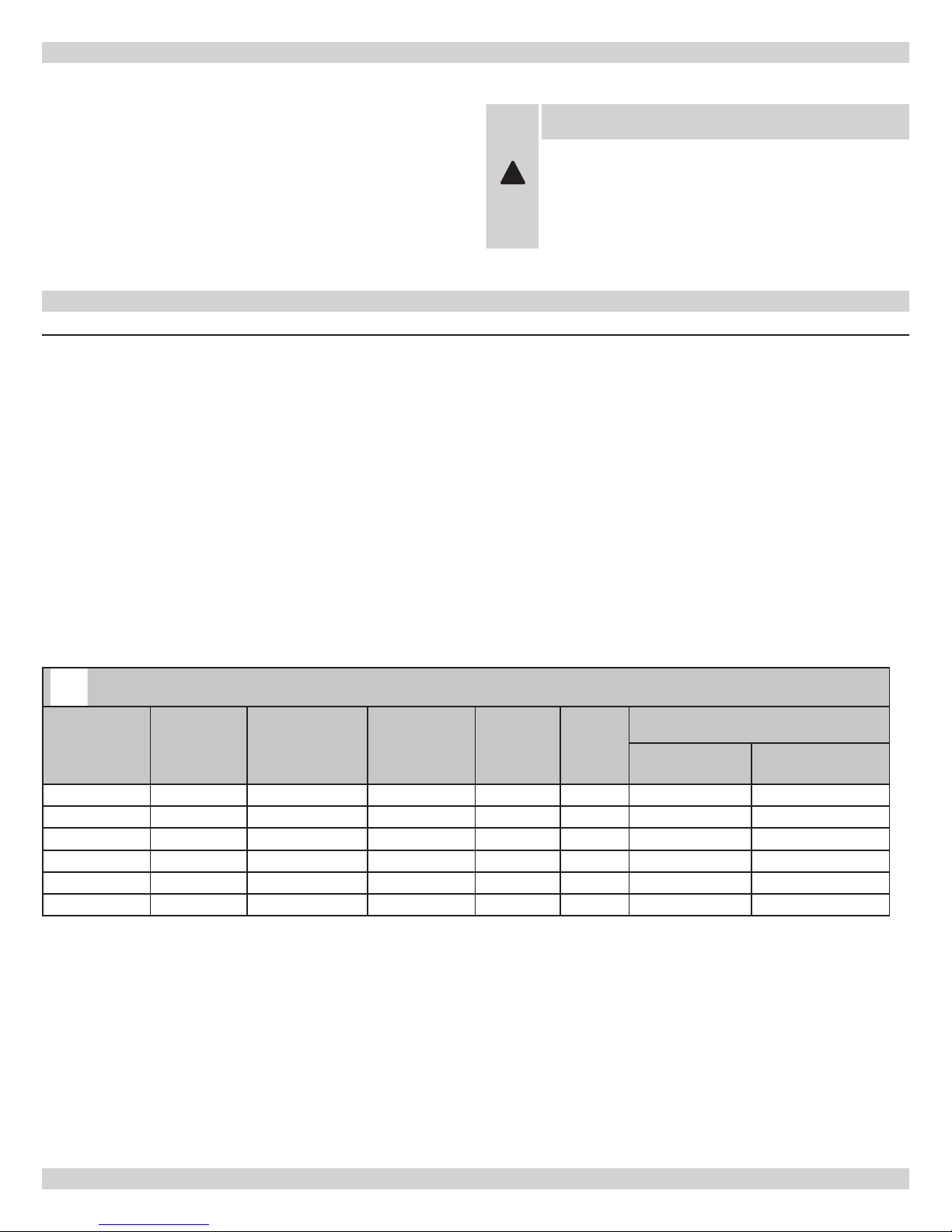
BOILER RATINGS AND CAPACITIES
Figure 1 - Boiler Ratings and Capacities
WARNING
Improper installation, adjustment, alteration,
service or maintenance can cause injury or
!
property damage. Refer to this manual. For
assistance or information consult a qualied
installer, service agency or the gas supplier.
Table 1 - RATINGS NATURAL AND PROPANE GASES
Model
XEB-2 2 42.5 36 31 11 4 3
XEB-3 3 75.0 63 55 14-1/4 4 3
XEB-4 4 112.5 94 82 17-1/2 4 3
XEB-5 5 150.0 125 109 20-3/4 4 3
XEB-6 6 187.5 155 135 24 4 4
XEB-7 7 225.0 186 162 27-1/4 4 4
* MBH = 1,000 Btuh = British Thermal Unit Per Hour. Boilers are equipped for altitudes up to 2,000 feet only. U.S.A. Only - For altitudes above 2,000
feet, ratings should be reduced at the rate of 4% for each 1,000 feet above sea level. Canada Only - Boilers may be used at high altitude (2,000-4500
feet/640-1350m) by using a certied eld conversion kit, resulting in a 10% de-rate. Contact Provincial authority having jurisdiction for installations
above 4500 ft (1350m) above sea level.
+ Heating Capacity based on D.O.E. (Department of Energy) test procedure.
Number of
Sections Input *MBH
New York City MEA Number 484-84-E Vol. IV.
The Ratings marked “Net I=B=R Ratings” indicate the
amount of remaining heat input that can be used to heat
the radiation or terminal units. The Net I=B=R Ratings
shown are based on an allowance of 1.15
Heating
Capacity *MBH
Net I=B=R
Rating *MBH
Width
A
Selection of boiler size should be based upon “Net I=B=R
Rating” being equal to or greater than the calculated heat
loss of the building.
The manufacturer should be consulted before selecting a
boiler for installations having unusual piping and pickup
Vent Diameter (Inches)
To Chimney
(Category I)
Horizontal Vent
(Category III)
requirements.
3

BOILER RATINGS & CAPACITIES
Boilers must stand on a noncombustible oor. If installed on
a combustible oor, please refer to the Repair Parts manual
for the appropriate Combustible Floor Base part number.
Gas-Fired Hot Water Boilers are low pressure, sectional cast
iron boilers Design Certied by CSA (Canadian Standards
Association) for use with Natural and Propane Gases. They
are constructed and hydrostatically tested for a maximum
working pressure of 50 psi (pounds per square inch) in
accordance with A.S.M.E. (American Society of Mechanical
Engineers) Boiler and Pressure Vessel Code, Section IV,
Rules for Construction of Heating Boilers.
Boilers For Use At High Altitude
This boiler is factory equipped for use at altitudes of
0-2,000 feet above sea level. For use at altitudes above
2,000 feet above sea level, the input ratings are reduced by
a change in main burner orice size.
U.S.A. Only - For altitudes above 2,000 feet above sea
level, input ratings should be reduced at the rate of 4% for
each 1,000 feet above sea level. Consult the National Fuel
Gas Code (NFPA54/ANSI Z223.1), or the manufacturer for
correct orice sizing information. High altitude orices are
available from the boiler manufacturer.
Canada Only - For altitudes in the range of 2,000-4,500
feet (610 - 1350m) above sea level, boilers may be eld
equipped for use at high altitude by using a certied eld
conversion kit. The change in main burner orice size
results in the boiler’s input rating being reduced by 10%.
The conversion shall be carried out by a manufacturer’s
authorized representative, in accordance with the
requirements of the manufacturer, provincial or territorial
authorities having jurisdiction and in accordance with
the requirements of CSA-B149 Natural Gas and Propane
Installation Code. The certied eld conversion kit includes
a conversion data plate, which must be attached to the
boiler adjacent to the rating plate, indicating that the boiler
has been converted for high altitude use. The conversion
data plate must be lled in with the correct conversion
information.
For altitudes over 4500 feet (1350m), contact Provincial
authority having jurisdiction.
BEFORE YOU START
Check to be sure you have the right size boiler before
starting installation. See rating and capacity table on
previous page. Also be sure the new boiler is for the type of
gas you are using. Check the rating plate on the right side
of the boiler.
Verify that the boiler is supplied with the correct type of
gas, fresh air for combustion, and a suitable electrical
supply. Also, the boiler must be connected to a suitable
chimney or horizontal venting system and an adequate
piping system. Finally, a thermostat, properly located, is
needed for control of the heating system. If you have any
doubts as to the various requirements, check with local
authorities and obtain professional help where needed.
Take the time to complete all of the steps for SAFE and
PROPER operation of the heating system.
If this boiler is installed in a building under construction,
special care must be taken to insure a clean combustion
air supply during the construction process. Airborne
particulates such as from drywall dust and from berglass
insulation can clog the burner ports and cause incomplete
combustion and sooting. Where required by the authority
having jurisdiction, the installation must conform to the
Standard for Controls and Safety Devices for Automatically
Fired Boilers, ANSI/ASME CSD-1.
Installation must conform to the requirements of the
authority having jurisdiction or, in the absence of such
requirements, to the National fuel Gas Code, ANSI Z223.1/
NFPA 54, and/or Natural Gas and Propane Installation
Code, CAN/CSA B149.1
NOTICE
Installers - Follow local regulations with
respect to installation of CO detectors.
Follow maintenance recommendations in this
instruction manual.
NOTICE
Keep boiler area clean and free from combustible materials, gasoline and other ammable
vapors and liquids
4
LOCATING THE BOILER
If the boiler is part of a planned heating system, locate
it where shown on your plan. If boiler is to be part of an
existing system, it is usually best to put it where the old
one was. If you plan to change location, you will need
additional materials as well as an adequate base. The
following rules apply:
The boiler must be level. Metal shims may be used
1.
under base legs for nal leveling.
Use a raised base if oor can become wet or damp.
2.
The vent pipe connection should be as short as
3.
possible.
Additional clearances for service may exceed clearances
4.
for re protection. Always comply with the minimum
re protection clearances shown on the boiler. An 18
inch clearance should be maintained on any side where
passage is required to access for cleaning, servicing,
inspection or replacement of any part that may need
attention. An 18 inch clearance is recommended on the
control side for servicing.
minimum clearances to combustible construction.
Consult the National Fuel Gas Code for further
information.
Equipment shall be installed in a location in which the
5.
facilities for ventilation permit satisfactory combustion
of gas, proper venting, and maintenance of ambient
temperature at safe limits under normal conditions of
use. Equipment shall be located so as not to interfere
with proper circulation of air. When normal inltration
does not provide the necessary air, outside air shall be
introduced (see “Fresh Air for Combustion”).
Advise owner to keep air passages free of obstructions.
6.
Ventilating and combustion air must enter boiler room
without restrictions.
The oor supporting the boiler must be
7.
noncombustible. If it is combustible, please refer to
Repair Parts List for the appropriate Combustible
Floor Base part number. We use a 2” Cladlite pad as a
combustible oor base. These are available from your
local supplier. Use 24” x 30” pad for 2-5 section boilers,
and a minimum 30” x 30” pad for 6-7 sections boilers.
The boiler must be centered on the combustible oor
base.
The boiler shall be installed such that the automatic
8.
gas ignition system components are protected from
water (dripping, spraying, rain, etc.) during appliance
operation and service (circulator replacement, control
replacement, etc..)
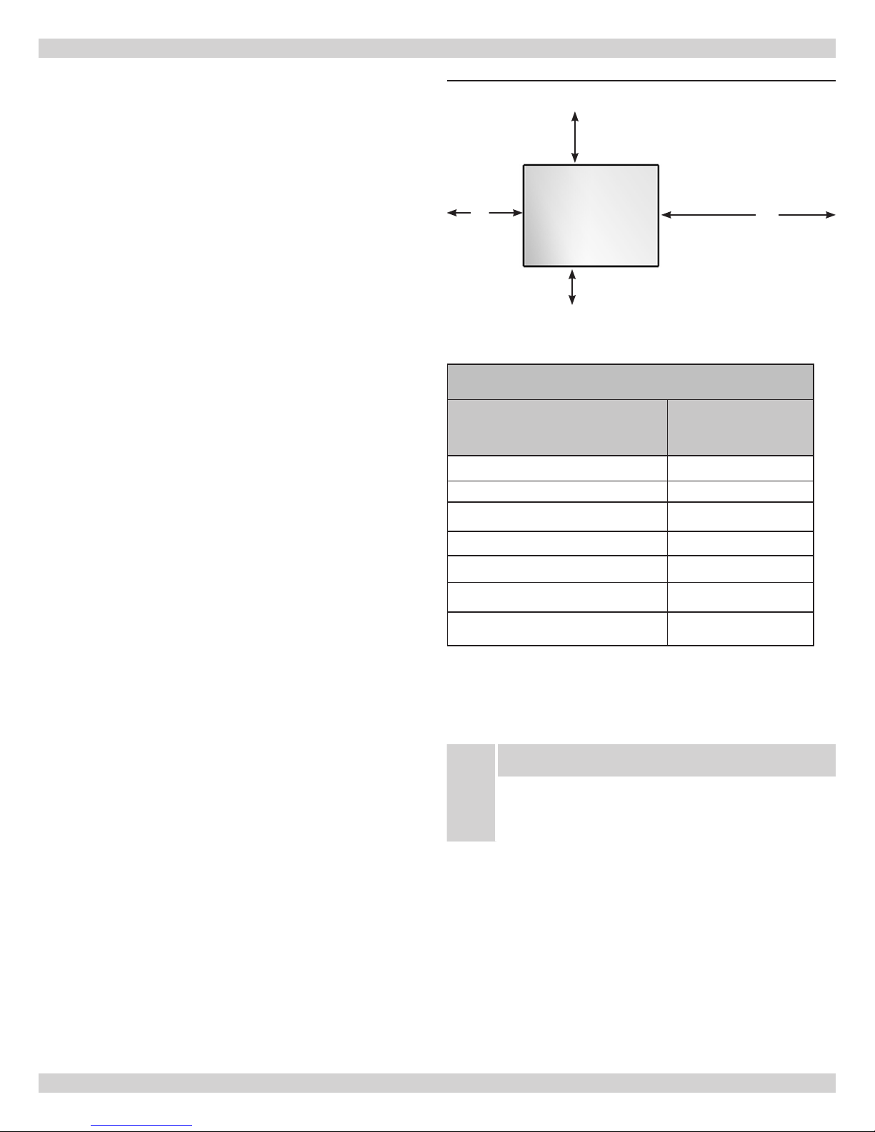
Figure 2
and Table 2 shows
Figure 2 - Minimum Clearances To Combustible
Construction
8”
Control Side
6”
Boiler
Rear
Opposite
18”
Front
Side
6”
Table 2 - BOILER MINIMUM CLEARANCE TO
COMBUSTIBLES
Unit
Top 6” (152mm)
Rear 6” (152mm)
Control Side 8” (203mm)
Opposite side 6” (152mm)
Front (Alcove) 18” (457mm)
Flue/Vent Connector 6” (152mm)
Near Boiler Piping 1” (24mm)
This unit must be set on a concrete or other noncombustible
material base or oor. IT MUST NOT BE INSTALLED ON
CARPETING.
NOTICE
This unit must be set on a concrete or other
noncombustible material base or oor. It must
not be installed on carpeting.
Minimum
Clearances
5

FRESH AIR FOR COMBUSTION
Provide combustion air and ventilation air in accordance
with the section “Air for Combustion and Ventilation,” of the
National Fuel Gas Code, ANSI Z223.1/NFPA 54, or Sections
8.2, 8.3 or 8.4 of Natural Gas and Propane Installation
Code, CAN/CSA B149.1, or applicable provisions of local
building codes.
•
All Outdoor Air. Provide permanent opening(s)
communicating directly or by ducts with outdoors.
Two Permanent Opening Method. Provide opening о
commencing within 12 inches of top and second
opening commencing within 12 inches of bottom
enclosure.
Provide make-up air where exhaust fans, clothes dryers,
and kitchen ventilation equipment interfere with proper
operation.
National Fuel Gas Code recognizes several methods
of obtaining adequate ventilation and combustion air.
Requirements of the authority having jurisdiction may
override these methods.
Engineered Installations. Must be approved by •
authority having jurisdictions.
Mechanical Air Supply. Provide minimum of 0.35
•
cfm per Mbh for all appliances located within space.
Additional requirements where exhaust fans installed.
Interlock each appliance to mechanical air supply
system to prevent main burner operation when
mechanical air supply system not operating.
All Indoor Air. Calculate minimum volume for all •
appliances in space. Use a different method if
minimum volume not available.
Standard Method. Cannot be used if known air о
inltration rate is less than 0.40 air changes per
hour. See Table 3 for space with boiler only. Use
equation for multiple appliances.
Volume ≥ 50 ft3 x Total Input [Mbh]
Known Air Inltration Rate. See Table 3 for о
space with boiler only. Use equation for multiple
appliances. Do not use an air inltration rate
(ACH) greater than 0.60.
Volume ≥ 15 ft3/ACH x Total Input [Mbh]
о
Refer to National Fuel Gas Code for opening
requirements between connection indoor spaces.
Direct communication with outdoors or
communicating through vertical ducts. Provide
minimum free area of 1 in2 per 4 Mbh of total
input rating of all appliances in enclosure.
Communicating through horizontal ducts.
Provide minimum free area of 1 in2 per 2
Mbh of total input rating of all appliances in
enclosure.
One Permanent Opening Method. Provide opening о
commencing within 12 inches of top of enclosure.
Provide minimum clearance of 1 inch on sides
and back and 6 inches on front of boiler (does not
supersede clearance to combustible materials).
Combination Indoor and Outdoor Air. Refer to о
National Fuel Gas Code for additional requirements
for louvers, grilles, screens and air ducts.
Combination Indoor and Outdoor Air. Refer to •
National Fuel Gas Code for application information.
National Gas and Propane Installation Code Requires providing air supply in accordance with:
Section 8.2 and 8.3 when combination of appliances •
has a total input of up to and including 400 Mbh (120
kW).
Does not have draft control device. о
Section 8.4 when combination of appliances has total •
input exceeding 400 Mbh (120 kW).
Refer to Natural Gas and Propane Installation Code •
for specic air supply requirements for enclosure
or structure where boiler is installed, including air
supply openings and ducts.
Table 3
Input Mbh
42.5 2125 6375 3188 2125 1594 1275 1063
75 3750 11250 5625 3750 2813 2250 1875
112.5 5625 16875 8438 5625 4219 3375 2813
150 7500 22500 11250 7500 5625 4500 3750
187.5 9375 28125 14063 9375 7031 5625 4688
225 11250 33750 16875 11250 8438 6750 5625
Standard
Method
0.1 0.2 0.3 0.4 0.5 0.6
Known Air Inltration Rate Method (Air Changes Per Hour)
6

INSTALLATION SYSTEM PIPING
WARNING
To avoid burns, scalding, or water damage due to discharge of steam and/or hot water during
operation, a discharge line shall be installed to relief valve outlet connection.
The discharge line shall:
connect to relief valve outlet and piped down to safe point of disposal.•
be of pipe size equal to or greater than that of the relief valve outlet over the entire •
length of discharge line;
have no intervening shutoff valve between safety relief valve and discharge to •
atmosphere (do not plug or place any obstruction in discharge line.
terminate freely to atmosphere where any discharge will be clearly visible and at no risk •
!
of freezing;
allow complete drainage of the valve and the discharge line;•
be independently supported and securely anchored to avoid applied stress on the relief •
valve;
be as short and straight as possible;•
terminate with plain end (not threaded);•
be constructed of material suitable for exposure to temperatures of 375° F or greater;•
Refer to local codes and appropriate ANSI/ASME Boiler and Pressure Vessel Code, Section
IV, or Boiler, Pressure Vessel and Pressure Piping Code, CSA B51 for additional installation
requirements.
Place boiler in the selected location (as near chimney
1.
as possible). Your boiler is shipped assembled. You
need only to install the circulator, ball valves, the relief
valve with a drain line to carry any water to a drain,
and the drain valve.
Install relief valve on 3/4” pipe nipple in tapped boiler
2.
opening. Pipe the discharge line following guidelines
in the preceding Warning. Refer to example shown in
Figure 4. The discharge line pipe size shall be equal
or greater than that of the relief valve outlet over the
entire length of discharge line with no intervening
shutoff valve between the safety relief valve and
discharge to atmosphere. The discharge line shall
terminate with a plain end to atmosphere where any
discharge will be clearly visible and is at no risk of
freezing. The discharge line shall be independently
supported to avoid applied stress on the relief valve.
The installation shall allow complete drainage of the
relief valve and the discharge line. The discharge
line shall be as short and straight as possible and
constructed of a material suitable for exposure to
temperatures of 375° F or greater.
Refer to local codes and appropriate ASME Boiler
3.
and Pressure Vessel Code for additional installation
requirements.
Install Drain Valve on lower left side of boiler as
4.
marked.
Install Temperature and Pressure Gauge into ¼”
5.
bushing threaded in tee furnished with supply piping
see
Figures 5 and 6
Connect Supply and Return Lines to boiler, as shown in
6.
Figures 5 and 6. The connections may require certain
additional ttings and parts.
.
7

INSTALLATION SYSTEM PIPING
Figure 4 - Relief Valve Discharge Piping
RELIEF VALVE
DISCHARGE
PIPING
Check local codes
for maximum
distance from
oor or other
allowable safe
point of discharge
Figure 6 - Forced Hot Water Typical Piping With
Zone Control Valve
Figure 5 -
Forced Hot Water Typical Piping
8

INSTALLATION SYSTEM PIPING
If you are installing an entire new heating system, rst
install all of your radiation units (panels, radiators or
cabinets) and the Supply and Return Mains - then make the
connections at the boiler.
In connecting the cold water supply to the water valve,
make sure that a clean water supply is available. When the
water supply is from a well or pump, a sand strainer should
be installed at the pump.
A hot water boiler installed above radiation level or as
required by the Authority having jurisdiction, must be
provided with a low water cutoff device either as a part of
the boiler or at the time of boiler installation. A periodic
inspection is necessary, as is ushing of oat type devices,
per manufacturers specic instructions.
When the boiler is used in connection with refrigeration
systems it shall be installed so that the chilled medium is
piped in parallel with the heating boiler with appropriate
valves to prevent the chilled medium from entering the
heating boiler (
If the boiler is connected to heating coils located in air
handling units where they may be exposed to refrigerated
air circulation, the piping system shall be equipped with
ow control valves or other automatic means to prevent
gravity circulation of the boiler water during the cooling
cycle.
Figure 7
).
Low Design Water Temperature Systems (Below
140° F) And Large Water Content Systems:
WARNING
Signicant condensation may form in this
!
boiler and/or the venting system if the boiler
is operated with return temperatures of less
than 120° F.
This condensation is corrosive and can eventually cause
severe damage to the boiler and venting system. The
minimum design return water temperature to prevent
this condensation in the boiler and venting is 120°F. The
minimum high limit setting is 140°F.
If the boiler is to be used in a heating system where design
water temperatures below 140°F are desired (e.g. radiant
oor heating), a 3-way or 4-way mixing valve or suitable
alternative is required to prevent low temperature return
water from entering the boiler. When using a mixing valve,
follow the manufacturer’s installation instructions.
If the boiler is to be connected to a system having a large
water content (such as a former gravity system), it is
suggested to use bypass piping shown in
Figure 8
.
Figure 7 - Piping Arrangements For Boiler
When Used In Connection With Refrigeration
System
Figure 8 - Bypass Piping
9

CHIMNEY & VENT PIPE CONNECTION
Check Your Chimney
This is a very important part of your heating system. It
must be clean, the right size, properly constructed and in
GOOD CONDITION. No boiler can function properly with a
bad chimney.
Installation must conform to the requirements of the
1.
authority having jurisdiction or, in the absence of such
requirements, to the National Fuel Gas Code, ANSI
Z223.1/NFPA 54, and/or Natural Gas and Propane
Installation Code, CAN/CSA B149.1.
The boiler’s induced draft blower has a 3” outlet. A
2.
3” X 4” increaser tting is included in the parts bag.
Locate the increaser tting on the outlet of the induced
draft blower, and secure gas-tight with a bead of
the furnished silicone sealant. The increaser tting is
required on this boiler for Category I venting, and 4”
is the minimum permissible vent diameter. This does
not imply that the vent connector is intended to be
4” diameter pipe. The vent connector shall be sized
according to the appropriate venting tables in the
National Fuel Gas Code or the Canadian Installation
Codes, and may be required to be larger than 4”
diameter.
NOTICE
The boiler installation for chimney venting
is not complete unless the 3” x 4” increaser
tting is located and secured.
These are high efciency boilers with a low stack or
3.
exhaust temperature.
If venting into a masonry chimney without a liner, line
4.
the chimney from top to bottom with either:
Listed Type B vent pipe A.
Listed exible vent linerB.
Poured ceramic liner. C.
Outside chimneys should not be used unless they are
5.
(choose one of the following):
Enclosed in a chaseA.
Lined with Type B vent pipeB.
Use a listed exible vent linerC.
Use a certied chimney lining systemD.
The vent connector from the boiler to the chimney
6.
should run as directly as possible with as few elbows as
possible.
Where possible, it is recommended to common vent
7.
the water heater and boiler. Consult the appropriate
Vent Sizing Tables in either the National Fuel Gas
Code, or the Canadian Installation Codes for specic
requirements of multiple appliance venting.
8.
9.
10.
11.
12.
13.
Minimum Vent Pipe Clearance
If the vent pipe must go through a crawl space, Type B
vent pipe should be used. Where vent pipe passes through
a combustible wall or partition, use a ventilated metal
thimble. The thimble should be 4 inches larger in diameter
than the vent pipe.
If boiler is installed with single wall vent, it must have
a 6” clearance between its surface and any combustible
material. A new Type B gas vent or exible liner must be
installed in accordance with the instructions furnished with
the vent. Maintain clearances as specied for the vent pipe.
Check the vent pipe to see if it is re-stopped where it goes
through the oor or ceiling. It should have an approved
vent cap with clearances from the roof as shown in
9
vent checked by local authorities.
Vent connectors serving appliances vented by natural draft
shall not be connected into any portion of mechanical draft
systems operating under positive pressure.
Removing Existing Boiler From Common Venting
System
When an existing boiler is removed from a common
venting system, the common venting system is likely to be
too large for proper venting of the appliances remaining
connected to it.
At the time of removal of an existing boiler, the following
steps shall be followed with each appliance remaining
connected to the common venting system placed in
operation, while the other appliance remaining connected
to the common venting system are not in operation.
1.
2.
If the boiler is the only appliance connected to the
vent, Type B vent pipe is recommended for the vent
connector.
Slope pipe up from boiler to chimney not less than 1/4”
per foot (21mm/m).
End of vent pipe must be ush with the inside face
of the chimney ue. Use a sealed-in thimble for the
chimney connection.
The sections of vent pipe should be fastened with sheet
metal screws to make the piping rigid. Use stovepipe
wires to support the pipe from above.
Do not connect to replace ue.
Do not install a damper on this boiler.
Figure
. If clearances are less than shown in
Seal any unused openings in the common venting
system.
Visually inspect the venting system for proper size and
horizontal pitch and determine there is no blockage or
restriction, leakage, corrosion and other deciencies
which could cause an unsafe condition.
Figure 9
, have the
10
 Loading...