

Dunkirk XEB-2, XEB-4, XEB-5, XEB-6, XEB-3 Installation, Operation & Maintenance Manual
...
R
XEB Series
Gas-Fired Hot Water
Induced Draft Boilers
INSTALLATION, OPERATION &
MAINTENANCE MANUAL
An ISO 9001-2000 Certified Company
DUNKIRK BOILERS
85 Middle Rd.
Dunkirk, NY 14048
www.dunkirk.com
P/N 14683001 Rev. B [11/09]

H
TABLE OF CONTENTS
Safety Symbols........................................................................................................................................................2
Installation Instructions .........................................................................................................................................3
Boiler Ratings And Capacities ................................................................................................................................3
Before You Start ......................................................................................................................................................4
Locating The Boiler .................................................................................................................................................5
Fresh Air For Combustion .......................................................................................................................................6
Installation System Piping .................................................................................................................................. 10
Chimney & Vent Pipe Connection ....................................................................................................................... 12
Horizontal Venting Instructions ....................................................................................................................... 15
Optional Horizontal Venting Instruction ........................................................................................................... 20
Gas supply Piping ................................................................................................................................................ 21
Electrical Wiring ................................................................................................................................................... 22
Sequence of Operation ........................................................................................................................................ 22
Wiring Diagrams .................................................................................................................................................. 23
Equipment & Optional Accessories .................................................................................................................... 24
Starting Your Boiler ............................................................................................................................................. 26
Checking and Adjusting ...................................................................................................................................... 27
Initial Operational Boiler Test Check-Out Procedure ........................................................................................ 29
Maintaining Your Boiler ...................................................................................................................................... 31
Service Hints......................................................................................................................................................... 32
NOTICE
IMPORTANT: Read the following instructions COMPLETELY before installing!
Keep this manual near boiler and retain for future reference.
NOTICE
SAFETY SYMBOLS
e following dened symbols are used throughout this manual to notify the reader of potential hazards of varying risk levels.
DANGER
Indicates an imminently hazardous situation which, if not
!
avoided, WILL result in death, serious injury or substantial
property damage.
CAUTION
!
Indicates an imminently hazardous situation which, if not
avoided, may result in injury or property damage.
Indicates an imminently hazardous situation which, if not
!
avoided, may result in death, serious injury or substantial
property damage.
Indicates information which should be followed to ensure
proper installation and operation.
WARNING
NOTICE
Natural gas or Propane
C.S.A. Certied for
Tested for 50 lbs. ASME
Working Pressure
2
H
INSTALLATION INSTRUCTIONS
ese instructions must be axed on or adjacent to the boiler.
is boiler cannot be used with all types of chimneys. Read these
instructions carefully before installing.
ese Gas-Fired Hot Water Boilers are low pressure, sectional cast
iron boilers Design Certied by C.S.A. (Canadian Standards Association) for use with Natural and Propane Gases. ey are constructed
and hydrostatically tested for a maximum working pressure of 50 psi
in accordance with A.S.M.E. Boiler and Pressure Vessel Code Section IV Standards for cast iron heating boilers.
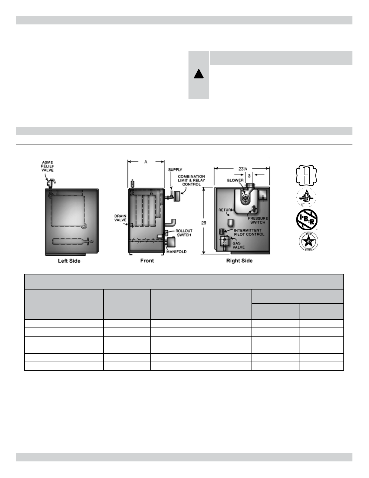
BOILER RATINGS AND CAPACITIES
Figure 1 - Boiler Ratings and Capacities
WARNING
Improper installation, adjustment, alteration, service or
!
maintenance can cause injury or property damage. Refer
to this manual. For assistance or information consult a
qualied installer, service agency or the gas supplier.
DESIGN CERTIFIED FOR
NATURAL AND PROPANE GAS
Table 1 -RATINGS NATURAL AND PROPANE GASES
Model
XEB-2 2 42.5 36 31 11 4 3
XEB-3 3 75.0 63 55 14-1/4 4 3
XEB-4 4 112.5 94 82 17-1/2 4 3
XEB-5 5 150.0 125 109 20-3/4 4 3
XEB-6 6 187.5 155 135 24 4 4
XEB-7 7 225.0 186 162 27-1/4 4 4
* MBH = 1,000 Btuh = British Thermal Unit Per Hour. Boilers are equipped for altitudes up to 2,000 feet only . U.S.A. Only - For altitudes above 2,000 feet, ratings should be reduced at the rate
of 4% for each 1,000 feet above sea level. Canada Only - Boilers may be used at high altitude by using a certied eld conversion kit, resulting in a 10% de-rate.
+ Heating Capacity based on D.O.E. (Department of Energy) test procedure.
Number of
Sections
AGA/CGA
Input *MBH
Heating
Capacity *MBH+
Net IBR
Rating *MBH
Width
A
Vent Diameter (Inches)
To Chimney
(Category I)
Horizontal Vent
(Category III)
New York City MEA Number 484-84-E Vol. IV.
e Ratings marked “Net I=B=R Ratings” indicate the amount of remaining heat input that can be used to heat the radiation or terminal
units. e Net I=B=R Ratings shown are based on an allowance of
1.15 in accordance with the factors shown on the I=B=R Standard as
published by e Hydronics Institute.
Selection of boiler size should be based upon “Net I=B=R Rating”
being equal to or greater than the calculated heat loss of the building.
e manufacturer should be consulted before selecting a boiler for
installations having unusual piping and pickup requirements.
3

BOILER RATINGS & CAPACITIES
ese boilers must stand on a noncombustible oor. If installed on
a combustible oor, please refer to the Repair Parts manual for the
appropriate Combustible Floor Base part number.
ese Gas-Fired Hot Water Boilers are low pressure, sectional cast
iron boilers Design Certied by CSA (Canadian Standards Association) for use with Natural and Propane Gases. ey are constructed
and hydrostatically tested for a maximum working pressure of 50psi
(pounds per square inch) in accordance with A.S.M.E. (American
Society of Mechanical Engineers) Boiler and Pressure Vessel Code
Section IV Standards for cast iron heating boilers.
Boilers For Use At High Altitude
is boiler is factory equipped for use at altitudes of 0-2,000 feet
above sea level. For use at altitudes above 2,000 feet above sea level,
the input ratings are reduced by a change in main burner orice size.
U.S.A. Only - For altitudes above 2,000 feet above sea level, input
ratings should be reduced at the rate of 4% for each 1,000 feet above
BEFORE YOU START
sea level. Consult the National Fuel Gas Code (NFPA54/ANSI
Z223.1-latest revision), or the manufacturer for correct orice sizing information. High altitude orices are available from the boiler
manufacturer.
Canada Only - For altitudes in the range of 2,000-4,500 feet above
sea level, boilers may be eld equipped for use at high altitude by
using a certied eld conversion kit. e change in main burner
orice size results in the boiler’s input rating being reduced by 10%.
e conversion shall be carried out by a manufacturer’s authorized
representative, in accordance with the requirements of the manufacturer, provincial or territorial authorities having jurisdiction and in
accordance with the requirements of the CSA-B149.1 and CSAB149.2 Installation Codes. e certied eld conversion kit includes
a conversion data plate, which must be attached to the boiler adjacent to the rating plate, indicating that the boiler has been converted
for high altitude use. e conversion data plate must be lled in with
the correct conversion information.
Check to be sure you have the right size boiler before starting the
installation. See rating and capacity table on previous page. Also be
sure the new boiler is for the type of gas you are using. Check the
rating plate on the right side of the boiler.
Verify that the boiler is supplied with the correct type of gas, fresh air
for combustion, and a suitable electrical supply. Also, the boiler must
be connected to a suitable chimney or horizontal venting system and
an adequate piping system. Finally, a thermostat, properly located, is
needed for control of the heating system. If you have any doubts as
to the various requirements, check with local authorities and obtain
professional help where needed. Take the time to complete all of the
steps for SAFE and PROPER operation of the heating system.
If this boiler is installed in a building under construction, special
care must be taken to insure a clean combustion air supply during the construction process. Airborne particulates such as from
drywall dust and from berglass insulation can clog the burner ports
and cause incomplete combustion and sooting. Where required by
the authority having jurisdiction, the installation must conform to
American Society of Mechanical Engineers Safety Code for Controls
and Safety Devices for Automatically Fired Boilers, No. CSD-1.
e installation must conform to the requirements of the authority
having jurisdiction or, in the absence of such requirements, to the
National Fuel Gas Code, ANSI Z223.1-latest revision.
In Canada, the boiler shall be installed according to CSA-B149.1 and
.2, Installation Code for Gas Burning Appliances and Equipment.
NOTICE
Installers - Follow local regulations with respect to installation of CO detectors. Follow maintenance recommendations in this instruction manual.
NOTICE
Keep boiler area clean and free from combustible materials, gasoline and other ammable vapors and liquids
4
LOCATING THE BOILER
If the boiler is part of a planned heating system, locate it where
shown on your plan. If boiler is to be part of an existing system, it
is usually best to put it where the old one was. If you plan to change
location, you will need additional materials as well as an adequate
base. e following rules apply:
1.
e boiler must be level. Metal shims may be used under base
legs for nal leveling.
2.
Use a raised base if oor can become wet or damp.
e vent pipe connection should be as short as possible.
3.
Additional clearances for service may exceed clearances for re
4.
protection. Always comply with the minimum re protection
clearances shown on the boiler. An 18 inch clearance should
be maintained on any side where passage is required to access
for cleaning, servicing, inspection or replacement of any part
that may need attention. An 18 inch clearance is recommended
on the control side for servicing.
Figure 2
and Table 2 shows
minimum clearances to combustible construction. Consult the
National Fuel Gas Code for further information.
5.
Equipment shall be installed in a location in which the facilities
for ventilation permit satisfactory combustion of gas, proper
venting, and maintenance of ambient temperature at safe limits
under normal conditions of use. Equipment shall be located so
as not to interfere with proper circulation of air. When normal
inltration does not provide the necessary air, outside air shall
be introduced (see “Fresh Air for Combustion”).
6.
Advise owner to keep air passages free of obstructions. Ventilating and combustion air must enter boiler room without
restrictions.
7.
e oor supporting the boiler must be noncombustible. If it is
combustible, please refer to Repair Parts List for the appropriate
Combustible Floor Base part number. We use a 2” Cladlite pad
as a combustible oor base. ese are available from your local
supplier. Use 24” x 30” pad for 2-5 section boilers, and a minimum 30” x 30” pad for 6-7 sections boilers. e boiler must be
centered on the combustible oor base.
8.
e boiler shall be installed such that the automatic gas ignition
system components are protected from water (dripping, spraying, rain, etc.) during appliance operation and service (circulator replacement, control replacement, etc..)
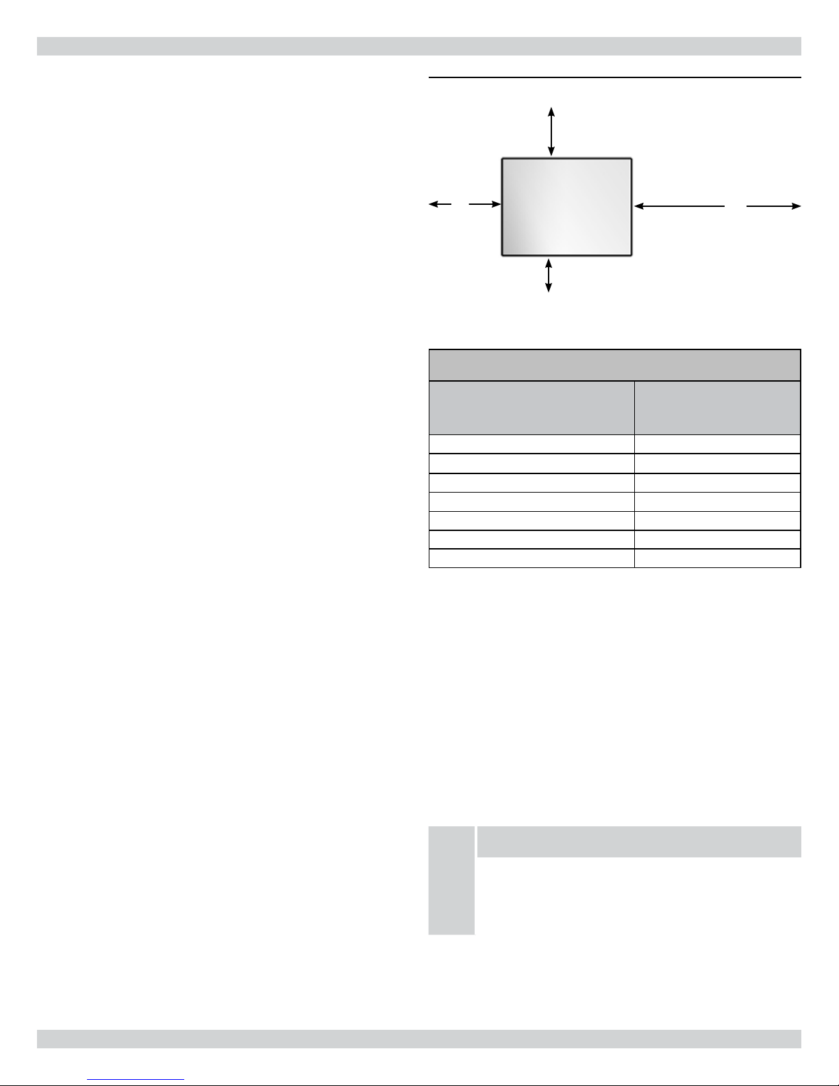
Figure 2 - Minimum Clearances To Combustible
Construction
8”
Control Side
Rear
Boiler
18”
Front
6”
Opposite Side
6”
Table 2 - BOILER MINIMUM CLEARANCE TO COMBUSTIBLES
Unit Minimum Clearances
Top 6”
Rear 6”
Control Side 8”
Opposite Side 6”
Front (Alcove) 18”
Flue/Vent Connector 6”
Near Boiler Piping 1”
This unit must be set on a concrete or other noncombustible material base
or oor. IT MUST NOT BE INSTALLED ON CARPETING.
NOTICE
is unit must be set on a concrete or other noncombustible material base or oor. It must not be installed on
carpeting.
5

FRESH AIR FOR COMBUSTION
NOTICE
Provision for combustion and ventilation air must be
in accordance with the National Fuel Gas Code, ANSI
Z223.1- latest revision, or applicable provisions of the local
building codes.
WARNING
Be sure to provide enough fresh air for combustion.
!
Enough air insures proper combustion and assures that no
hazard will develop due to the lack of oxygen.
You must provide for enough fresh air to assure proper combustion.
e re in the boiler uses oxygen. It must have a continuous supply.
e air in a house contains only enough oxygen to supply the burner
for a short time. Outside air must enter the house to replace that
used by the burner. Study following examples 1 and 2 to determine
your fresh air requirements.
NOTICE
If you use a replace or a kitchen or bathroom exhaust fan,
you should install an outside air intake. ese devices will
rob the boiler and water heater of combustion air.
Sizing Air/Ventilation Openings
NOTICE
Air openings must be sized to handle all appliances and
air movers (exhaust fans, etc.) using the air supply. For
air openings into spaces containing other appliances in
addition to the boiler refer to the National Fuel Gas Code,
ANSI Z223.1 for sizing.
If No Other Gas Appliances In The Same Space
Provide air openings into the boiler space as described in this section and the National Fuel Gas Code, ANSI Z223.1. Direct exhaust
installations require air for combustion and ventilation. Direct vent
installations may require air openings for ventilation (to prevent
overheating of boiler controls and boiler space).
When Other Gas Appliances Share the Same Space
For air openings into spaces containing other appliances in addition
to the boiler refer to the National Fuel Gas Code, ANSI Z223.1 for
sizing.
6
FRESH AIR FOR COMBUSTION
EXAMPLE 1: Boiler Located In Unconned Space
An unconned space is dened as a space whose volume is not less than 50 cubic feet per 1,000 Btu per hour of the total input rating of all
appliances installed in that space.
If your boiler is in an open area (non-partitioned basement) in a conventional house, the air that leaks through the cracks around doors and
windows will usually be adequate to provide air for combustion. e doors should not t tightly. Do not caulk the cracks around the windows.
NOTICE
Equipment located in buildings of tight construction shall be provided with air for combustion, ventilation, and dilution of ue
gases using the methods described in example 2 (below) or shall be specially engineered. e authority having jurisdiction must
approve specially engineered installations. A building of tight construction is dened as: 1) walls exposed to the outdoor atmosphere have a continuous water vapor retarder with a rating of one perm or less with openings gasketed or sealed; and 2) openable
windows and doors which meet the air leakage requirements of the International Energy Conservation Code, Section 502.1.4; and
3) caulking or sealants are applied to areas such as joints around window and door frames, between sole plates and oors, between
wall-ceiling joints, between wall panels, at penetrations for plumbing, electrical and gas lines, and at other openings.
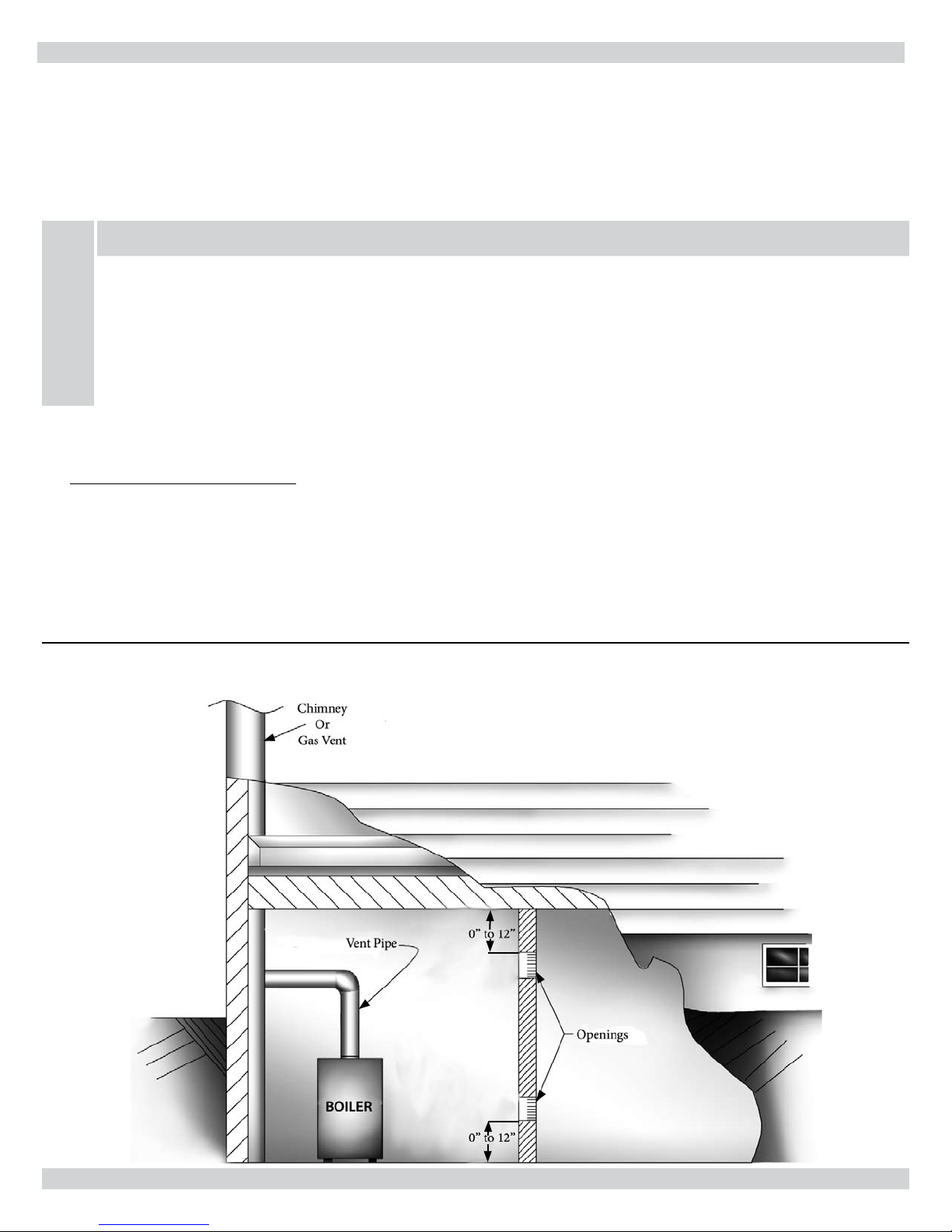
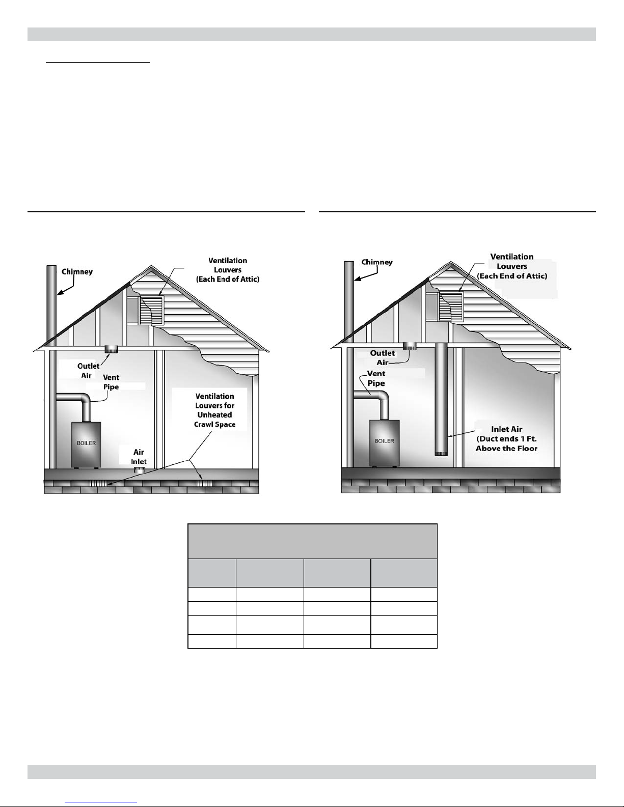
EXAMPLE 2: Boiler Located in Conned Space
All Air from Inside the Building:1.
an additional room(s) of sucient volume so that the combined volume of all spaces meets the criteria for an unconned space. e
total input of all gas utilization equipment installed in the combined space shall be considered in making this determination. Each opening shall have a minimum free area of one square inch per 1,000 Btu per hour of the total input rating of all gas utilization equipment in
the conned space, but not less that 100 square inches. One opening shall be within 12 inches of the top and one within 12 inches of the
bottom of the enclosure. e minimum dimension of air openings shall not be less than 3 inches (see
e conned space shall be provided with two permanent openings communicating directly with
Figure 3A
).
Figure 3A - Boiler Located in Conned Space
7
FRESH AIR FOR COMBUSTION
All Air from Outdoors:2.
e conned space shall communicate with the outdoors in accordance with Methods A or B below. e
minimum dimension of air openings shall not be less than 3 in. Where ducts are used, they shall be of the same cross-sectional area as
the free area of the openings to which they connect.
Method A: Two permanent openings, one commencing within 12 inches of the top, and one commencing within 12 inches of the bot-
tom, of the enclosure shall be provided. e openings shall communicate directly, or by the ducts, with the outdoors or spaces (crawl or
attic) that freely communicate with the outdoors.
Where directly communicating with the outdoors (see 1.
(see
Figure 3C
Figure 3B
), each opening shall have a minimum free area of 1 sq. in. per 4000 Btu per hour of total input rating of all equip-
) or where communicating to the outdoors through vertical ducts
ment in the enclosure.
Figure 3B - Directly Communicating to the Outdoors
Figure 3C - Vertical Ducts Communicating to the Outdoors
FRESH AIR DUCT CAPACITIES (1 Square inch per 4,000 Btuh)
Fresh Air
Duct Size
3” x 12” 144,000 108,000 36,000
8” x 8” 256,000 192,000 64,000
8” x 12” 384,000 288,000 96,000
8 ½” x 16” 512,000 384,000 128,000
Louver Allowance
e free areas of openings means the area aer reduction for any installed louvers or grilles. Be
sure to consider this reduction when sizing the air openings.
see Figures - 3B and 3C
100% Free Area
1/4” Wire Mesh
Table 3
75% Free Area
Metal Louvers
8
25% Free Area
Wood Louvers
FRESH AIR FOR COMBUSTION
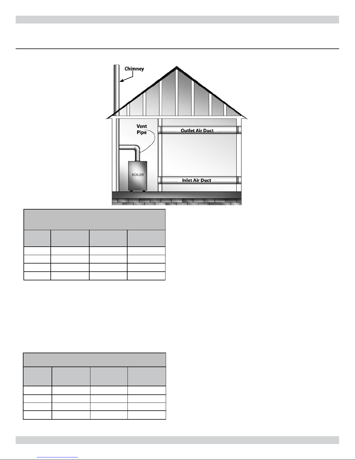
Where communicating with the outdoors through horizontal ducts (see 2.
of 1 area of sq. in. per 2000 Btu per hour of total rating of all equipment in the enclosure.
Figure 3D - Horizontal Ducts Communicating to the Outdoors
Figure 3D
), each opening shall have a minimum free area
Table 4
FRESH AIR DUCT CAPACITIES (1 Square inch per 2,000 Btuh)
see Figure 3D
Fresh Air
Duct Size
3” x 12” 72,000 54,000 18,000
8” x 8” 128,000 96,000 32,000
8” x 12” 192,000 144,000 48,000
8 ½” x 16” 256,000 192,000 64,000
100% Free Area
1/4” Wire Mesh
75% Free Area
Metal Louvers
25% Free Area
Wood Louvers
Louver Allowance
e free areas of openings means the area aer reduction for any
installed louvers or grilles. Be sure to consider this reduction when
sizing the air openings.
Method B: One permanent opening commencing within 12 inches of the top of the enclosure shall be permitted where the equipment has
clearance of at least 1 inch from the sides and back and 6 inches from the front of the appliance. e opening shall directly communicate
with the outdoors or shall communicate through a vertical or horizontal duct to the outdoors or to a crawl space or attic that freely communicate with the out doors, and shall have a minimum free area of:
1 sq. inch per 3000 Btu per hour of the total input of all equipment located in the enclosure (see chart below).1.
Not less than the sum of the areas of all vent connectors in the conned space.2.
Table 5
FRESH AIR DUCT CAPACITIES (1 Square inch per 3,000 Btuh)
Fresh Air
Duct Size
3” x 12” 108,000 81,000 27,000
8” x 8” 192,000 144,000 48,000
8” x 12” 288,000 216,000 72,000
8 ½” x 16” 384,000 288,000 96,000
100% Free Area
1/4” Wire Mesh
75% Free Area
Metal Louvers
25% Free Area
Wood Louvers
Louver Allowance
e free areas of openings means the area aer reduction for any
installed louvers or grilles. Be sure to consider this reduction when
sizing the air openings.
9

INSTALLATION SYSTEM PIPING
WARNING
To avoid burns, scalding, or water damage due to discharge of steam and/or hot water during operation, a discharge
line shall be installed to relief valve outlet connection.
e discharge line shall:
connect to relief valve outlet and piped down to safe point of disposal.•
be of pipe size equal to or greater than that of the relief valve outlet over the entire length of discharge line;•
have no intervening shuto valve between safety relief valve and discharge to atmosphere (do not plug or •
place any obstruction in discharge line.
!
terminate freely to atmosphere where any discharge will be clearly visible and at no risk of freezing;•
allow complete drainage of the valve and the discharge line;•
be independently supported and securely anchored to avoid applied stress on the relief valve;•
be as short and straight as possible;•
terminate with plain end (not threaded);•
be constructed of material suitable for exposure to temperatures of 375° F;•
or greater.•
Refer to local codes and appropriate ASME Boiler and Pressure Vessel Code for additional installation requirements.
Place boiler in the selected location (as near chimney as pos-
1.
sible). Your boiler is shipped assembled. You need only to
install the circulator, ball valves, the relief valve with a drain line
to carry any water to a drain, and the drain valve.
2.
Install relief valve on 3/4” pipe nipple in tapped boiler opening.
Pipe the discharge line following guidelines in the preceding
Warning. Refer to example shown in Figure 4. e discharge
line pipe size shall be equal or greater than that of the relief
valve outlet over the entire length of discharge line with no
intervening shuto valve between the safety relief valve and discharge to atmosphere. e discharge line shall terminate with
a plain end to atmosphere where any discharge will be clearly
visible and is at no risk of freezing. e discharge line shall be
independently supported to avoid applied stress on the relief
valve. e installation shall allow complete drainage of the
relief valve and the discharge line. e discharge line shall be as
short and straight as possible and constructed of a material suitable for exposure to temperatures of 375° F or greater.
Refer to local codes and appropriate ASME Boiler and Pressure
3.
Vessel Code for additional installation requirements.
4.
Install Drain Valve on lower le side of boiler as marked.
Install Temperature and Pressure Gauge into ¼” bushing
5.
threaded in tee furnished with supply piping See
and 6
).
6.
Connect Supply and Return Lines to boiler, as shown in
ures 5 and 6. e connections may require certain additional
ttings and parts.
Figures 5
Fig-
10
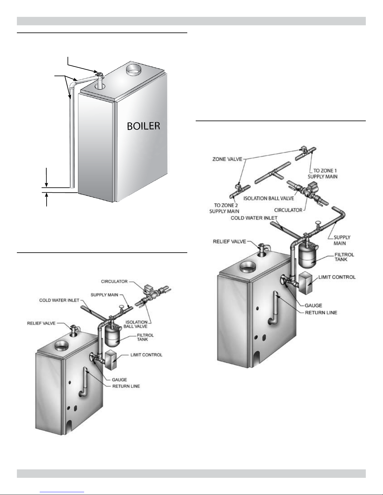
Figure 4 - Relief Valve Discharge Piping
RELIEF VALVE
DISCHARGE
PIPING
Check local codes
for maximum
distance from
oor or other al-
lowable safe point
of discharge
INSTALLATION SYSTEM PIPING
Figure 6 - Forced Hot Water Typical Piping With Zone
Control Valve
Figure 5 -
Forced Hot Water Typical Piping
11
 Loading...