

Page 1
GAS-FIRED,DIRECTVENT,
CONDENSING, HOT WATER BOILER
INSTALLATION, OPERATION&
MAINTENANCE MANUAL
DUNKIRK BOILERS
85 Middle Rd.
Dunkirk, NY 14048
www. dunkirk, com
P/N# 14683301,Rev.C [12/2010]
Page 2
90-75
90= 1 O0
These instructions
must be affixed on or
adjacent to the boiler.
iiiiiiiiiiiiiiiiiiiiiiiiiiiiiiiiiiiiiiiiiiiiiii
iiiiiiiiiiiiiiiiiiiiiiiiiiiiiiiiiiiiiiiiiiiiiiitheinstallation.
iiiiiiiiiiiiiiiiiiiiiiiiiiiiiiiiiiiiiiiiiiiiiiiSave this manual for reference.
Improper installation, adjustment, alteration,
service, or maintenance can cause injury or
property damage. Refer to this manual. For
assistance or additional information consult a
qualified installer, service agency, or the gas
supplier.
Read all instructions carefully before starting
Page 3
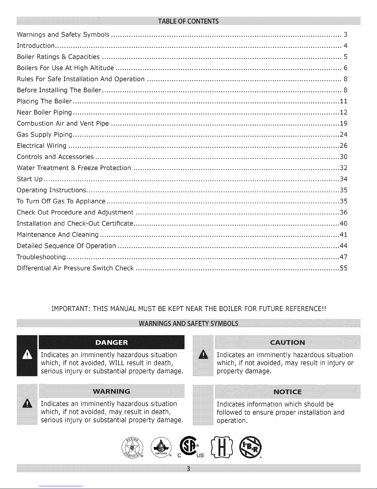
Warnings and Safety Symbols ....................................................................................................... 3
Introduction ................................................................................................................................ 4
Boiler Ratings & Capacities ........................................................................................................... 5
Boilers For Use At High Altitude ..................................................................................................... 6
Rules For Safe Installation And Operation ....................................................................................... 8
Before Installing The Boiler ........................................................................................................... 8
Pladn( The Boiler ....................................................................................................................... 11
Near Boiler Piping ....................................................................................................................... 12
Combustion Air and Vent Pipe ...................................................................................................... 19
Gas Supply Piping ....................................................................................................................... 24
Electrical Wiring ......................................................................................................................... 26
Controls and Accessories ............................................................................................................. 30
Water Treatment & Freeze Protection ............................................................................................ 32
Start Up .................................................................................................................................... 34
Operating Instructions ................................................................................................................. 35
To Turn Off Gas To Appliance ........................................................................................................ 35
Check Out Procedure and Adjustment ........................................................................................... 36
Installation and Check-Out Certificate ............................................................................................ 40
Maintenance And Cleaning ........................................................................................................... 41
Detailed Sequence Of Operation ................................................................................................... 44
Troubleshooting .......................................................................................................................... 47
Differential Air Pressure Switch Check ........................................................................................... 55
IMPORTANT: THIS MANUAL MUST BE KEPT NEAR THE BOILER FOR FUTURE REFERENCE!!
Indicates an imminently hazardous situation
which, if not avoided, WILL result in death,
serious injury or substantial property damage,
which, ifn ot avoid ed, mayresu It in death,
serious injury or substantial property damage.
Indicates an imminently hazardous situation
which, if not avoided, may result in injury or
property damage.
Indicates information which should be
followed to ensure proper installation and
operation.
Page 4
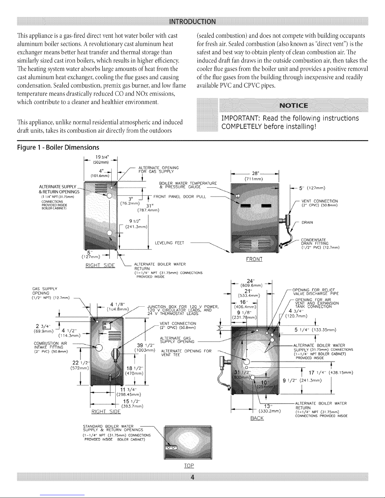
This appliance is a gas-fired direct vent hot water boiler with cast
aluminum boiler sections. A revolutionary cast aluminum heat
exchanger means better heat transfer and thermal storage than
sirnilarly sized cast iron boilers, which results in higher efiqciency.
The heating system water absorbs large amounts of heat from the
cast aluminum heat exchanger, cooling the flue gases and causing
condensation. Sealed combustion, premix gas burner, and low flame
temperature means drastically reduced CO and NOx emissions,
which contribute to a cleaner and healthier environment.
(sealedcombustion)and does not competewith building occupants
for fresh air. Sealedcombustion (also known as"directvent") is the
safestand best wayto obtainplentyofcleancombustion air. The
induced draft fan drawsin the outside combustion air,then takesthe
coolerfluegasesfrom the boilerunit and providesa positiveremoval
of thefluegasesfrom the building through inexpensiveand readily
availablePVCand CPVC pipes.
Thisappliance,unlikenormal residential atmospheric and induced
draft units, takes itscombustion airdirectly from the outdoors
Figure 1 - Boiler Dimensions
19 3/4"
(502ram}
ALTERNATE SUPP|.Y _,
& RETURN OPENINGS
CONN{::<7_ONS
_ROVID_DINEID_
gOILER(A@_[ [
RETURN
(1_/4' _4_P_ (3175_'nm) CONNECTIOP#S
PROVID£FJ INSIDE
4 V8"......(iu4.Smm)
22
(572mm)
JUNCTION BOX FOR _20 V POWER,
120 V CIRCULATOR LEADS, AND
24 V THERMOSTAT LEADS
VENT CONNECTION
CPvC) (50,Smm}
ALTERNATE GAS
39 112"
( _O05mm)
SUPPLY OPENING
ALTERNATE OPENING FOR
VENT TEE
IMPORTANT: Read the following instructions
COMPLETELY before installing!
( t 27r,nm)
VENT CONNECTION
(2" CPvC) (SO gin.' 0
DRA_N
CONDENSATE
DRAN FITIINO
(1/2" pro) O2.Tmm)
FRONT
(609.6mr,n}
2t"
24 _
(833 4ram)
VENT AND EXPANSION
TANK CONNECT{ON
FOR AIR
L
PROV_O_D iNS_g£ 80{LER C_81NE[)
13 ¸,1
(350.2mm)
BACK
TO_
Page 5
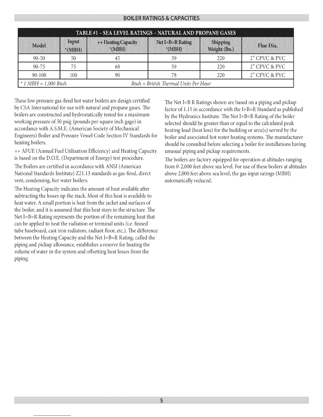
90-50 50 45 39 220 2" CPVC & PVC
90-75 75 68 59 220 2" CPVC & PVC
90-100 100 90 78 220 2" CPVC & PVC
*1MBH = 1,000 Btuh Btuh =British Thermal Units Per Hour
These low pressure gas-fired hot water boilers are design certified
by CSA International for use with natural and propane gases. The
boilers are constructed and hydrostatically tested for a rnaximurn
working pressure of 50 psig (pounds per square inch gage) in
accordance with A.S.M.E. (Arnerican Society of Mechanical
Engineers) Boiler and Pressure Vessel Code Section IV Standards for
heating boilers.
++ AFUE (Annual Fuel Utilization Efficiency) and Heating Capacity
is based on the D.O.E. (Departrnent of Energy) test procedure.
The Boilers are certified in accordance with ANSI (American
National Standards Institute) Z21.13 standards as gas-fired, direct
vent, condensing, hot water boilers.
The Heating Capacity indicates the arnount of heat available after
subtracting the losses up the stack. Most of this heat is available to
heat water. A srnall portion is heat frorn the jacket and surfaces of
the boiler, and it is assumed that this heat stays in the structure. The
Net I=B=R Rating represents the portion of the rernaining heat that
can be applied to heat the radiation or terminal units (i.e. finned
tube baseboard, cast iron radiators, radiant floor, etc.). Thedifference
between the Heating Capacity and the Net I=B=R Rating, called the
piping and pickup allowance, establishes a reserve for heating the
volurne of water in the systern and offsetting heat losses frorn the
piping.
The Net I=B R Ratings shown arebased on a piping and pickup
factor of 1.15 in accordance with the I=B=R Standard as published
by the Hydronics Institute. The Net I=B=R Rating of the boiler
selected should be greater than or equal to the calculated peak
heating load (heat loss) for the building or area(s) served by the
boiler and associated hot water heating systems. The rnanufacturer
should be consulted before selecting a boiler for installations having
unusual piping and pickup requirernents.
The boilers are factory equipped for operation at altitudes ranging
frorn 0-2,000 feet above sea level. For use of these boilers at altitudes
above 2,000 feet above sea level, the gas input ratings (MBH)
autornatically reduced.
Page 6
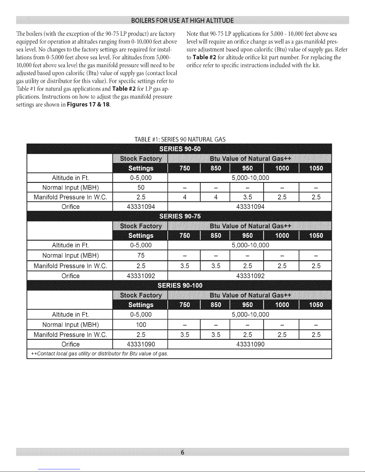
Theboilers(with the exceptionof the 90-75LPproduct) arefactory
equipped foroperation at altitudesranging from 0-10,000feetabove
sealevel.Nochanges to the factory settings arerequired for instal-
lationsfrom 0-5,000feet abovesealevel.Foraltitudes from 5,000-
10,000feetabovesealevel thegasmanifoldpressurewill need to be
adjustedbased upon calorific (Btu)valueof supplygas (contact local
gasutilityor distributor for thisvalue). For specificsettings refer to
Table#1 for natural gasapplicationsand Table #2 for LPgasap-
plications.Instructions on how to adjust the gasmanifold pressure
settings are shown in Figures 17 & 18.
TABLE#1: SERIES90 NATURAL GAS
Note that 90-75 LP applications for 5,000- 10,000 feet above sea
level will require an orifice change aswell as a gas manifold pres-
sure adjustment based upon calorific (Btu) value of supply gas. Refer
to Table #2 for altitude orifice kit part number. For replacing the
orifice refer to specific instructions included with the kit.
Altitude in Ft.
Normal Input (MBH)
Manifold Pressure In W.C.
Orifice
Altitude in Ft. 0-5,000 5,000-10,000
Normal Input (MBH) 75 - _ - - / - / -
Manifold Pressure In W.C. 2.5 3.5 / 3.5 2.5 / 2.5 / 2.5
Orifice 43331092 43331092
Altitude in Ft.
Normal Input (MBH)
Manifold Pressure In W.C.
Orifice
++Contact local gas utility or distributor for Btu value of gas.
0-5,000
50
2.5
43331094
0-5,000
100
2.5
43331090
5,000-10,000
- i - - i -
4 1 4 2.5 1 2.5
t t
3.5 3.5 2.5 2.5
- ]
3.5 _
43331094
5,000-10,000
-t
2.5
43331090
Page 7
i_i_i_i_i_i_i_i_i_i_i_i_i_i_i_i_i_i_i_i_i_i_i_i_i_i_i_i_i_i_i_i_i_i_i_i_i_i_i_i_i_i_i_i_i_i_i
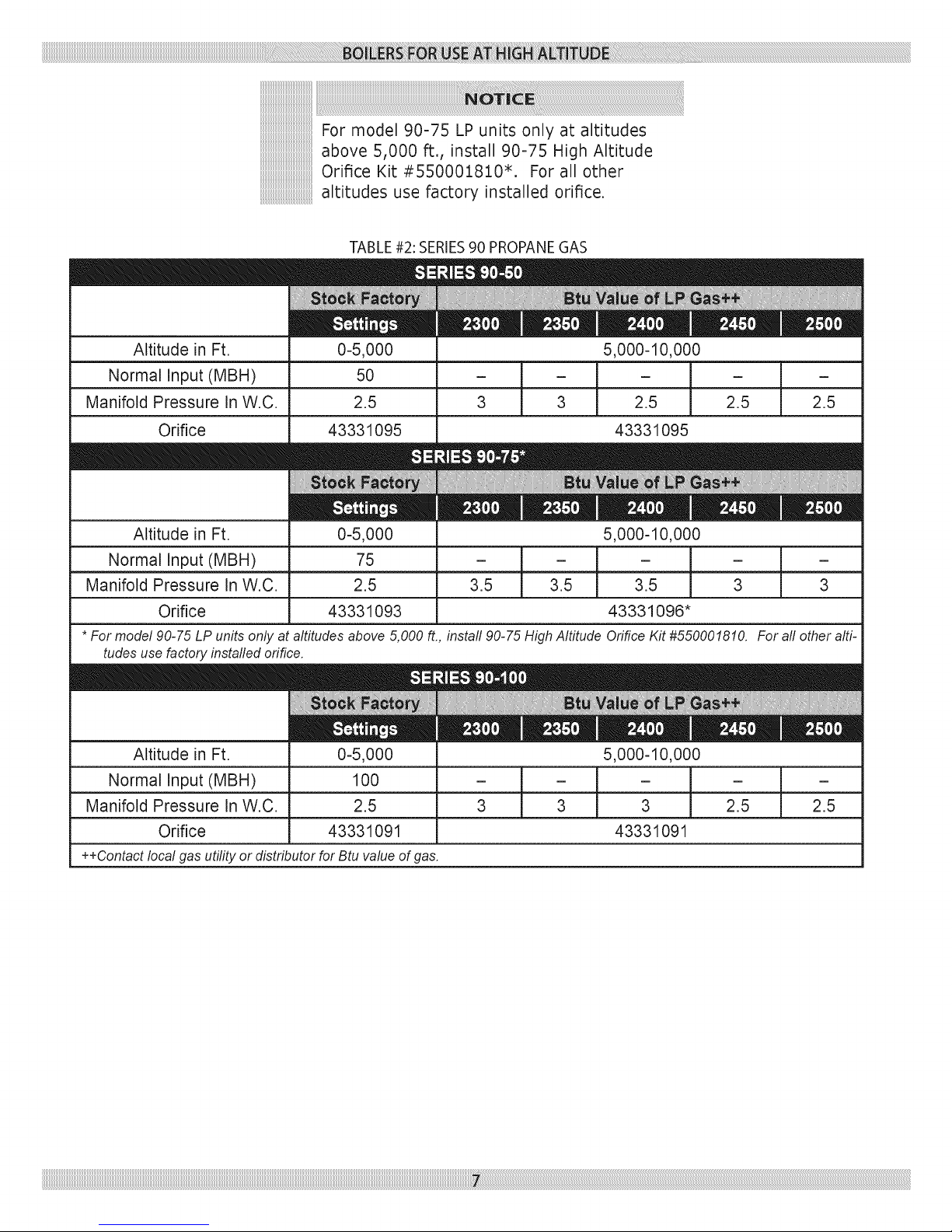
For model 90-75 LP units only at altitudes
above 5,000 ft., install 90-75 High Altitude
Orifice Kit #550001810*. For all other
altitudes use factory installed orifice.
TABLE#2: SERIES90 PROPANEGAS
Altitude in Ft.
Normal Input (MBH)
Manifold Pressure In W.C.
Orifice
Altitude in Ft.
Normal Input (MBH) - - [ - -
Manifold Pressure In W.C. 2.5 3.5 3.5 l 3 3
Orifice 43331093
* For model 90-75 LP units only at altitudes above 5,000 ft., install 90-75 High Altitude Orifice Kit #550001810. For all other alti-
tudes use factory installed orifice.
Altitude in Ft.
Normal Input (MBH)
Manifold Pressure In W.C.
Orifice
++Contact local gas utility or distributor for Btu value of gas.
0-5,000
50
2.5
43331095
0-5,000
75
0-5,000
100
2.5
43331091
5,000-10,000
[ - ]
3 3 2.5 2.5
43331095
5,000-10,000
- ]
3.5 l
43331096*
5,000-10,000
3 3 2.5 2.5
43331091
Page 8
1. Readtheentireinstallationmanualbeforebeginningtheinstal-
lation.Failuretofollowtheserulesforsafeinstallationand
operationandtheseinstructionscouldcauseamalfunction
oftheboilerandresultindeath,seriousbodilyinjury,and/or
propertydamage.
2. Checkallapplicablestateandlocalbuildingcodesandutil-
itycompanyrequirementsbeforeinstallation.Theinstallation
mustconforrnwiththeserequirementsintheirentirety.Inthe
absenceofthesecodes,useNFPAInstallationCodesandgood
industrypractice.
3. Beforeservicingtheboiler-allowtheboilertocool.Always
shutoffanyelectricityandgassupplyconnectedtotheboiler
priortoservicing.
4. Inspectgaslineforleaks.
5. Becertaingasinputrateiscorrect.Overfiringmayresultin
earlyfailureoftheboilersections.Thismaycausedangerous
operation.Underfiringmayresultintoomuchairforthepre-
mixburnercausingpoororlossofcombustion.
6. Never vent the products of combustion from this boiler to an
enclosed space. Always vent to the outdoors. Never vent to
another room or to inside a building.
7. Be sure there is adequate outdoor air supply to boiler for com-
plete combustion.
8. Follow a regular service and maintenance schedule for efficient
and safe operation.
9. Keep boiler area clean of debris and flee of combustible and
flammable rnaterials.
10.
Proper through the wall or through the roof cornbustion vent-
ing shallbe in accordance with the materials and methods
described in this manual. Installation must complywith local
codes.
11.
This boiler and related hot water heating systems are not do it
yourself items. They must be installed and serviced by qualified
professionals.
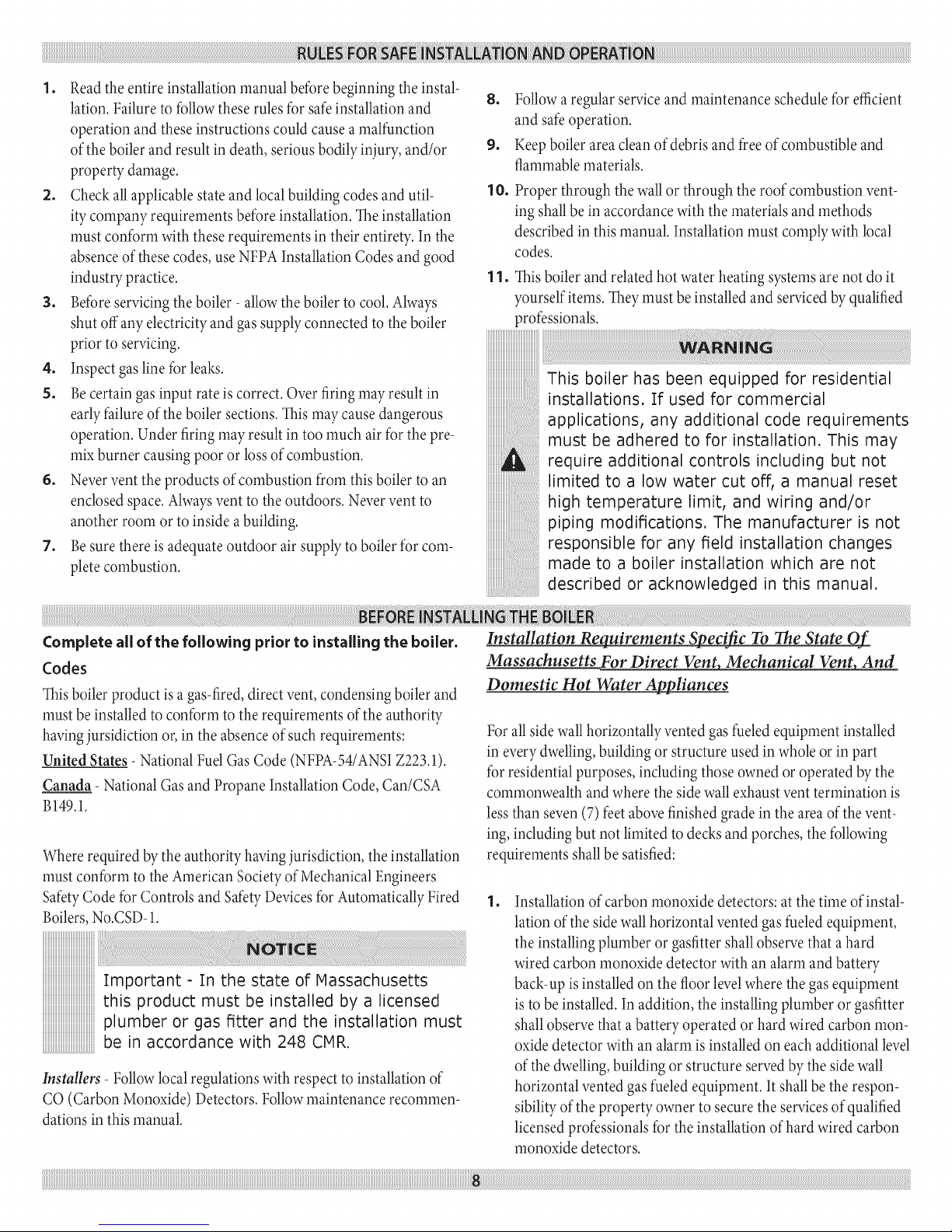
This boiler has been equipped for residential
installations. If used for commercial
applications, any additional code requirements
must be adhered to for installation. This may
require additional controls including but not
limited to a low water cut off, a manual reset
high temperature limit, and wiring and/or
piping modifications. The manufacturer is not
responsible for any field installation changes
made to a boiler installation which are not
described or acknowledged in this manual.
Complete all of the following prior to installing the boiler.
Codes
This boiler product is a gas-fired, direct vent, condensing boiler and
must be installed to conforrn to the requirernents of the authority
having jursidiction or, in the absence of such requirements:
United States- National Fuel Gas Code (NFPA-54/ANSI Z223.1).
Canada- National Gas and Propane Installation Code, Can/CSA
B149.1.
Where required bythe authority havingjurisdiction, the installation
must conform to the Arnerican Societyof MechanicalEngineers
SafetyCode for Controls and SafetyDevicesfor AutomaticallyFired
Boilers,No.CSD-1.
iiiiiiiiiiiiiiiiiiiiiiiiiiiiiiiiiiiiiiiiiiiiii_
Important - In the state of Massachusetts
this product must be installedby a licensed
plumber or gas fitter and the installation must
be in accordance with 248 CHR.
Installers- Followlocal regulationswith respect to installation of
CO (Carbon Monoxide) Detectors. Followmaintenance recommen-
dations in this manual.
Installation Requirements Specific To The State Of
Massachusetts For Direct Vent, Mechanical Vent_ And
Domestic Hot Water Appliances
For all side wall horizontally vented gas fueled equiprnent installed
in every dwelling, building or structure used in whole or in part
for residential purposes, including those owned or operated by the
comrnonwealth and where the side wall exhaust vent terrnination is
less than seven (7) feet above finished grade in the area of the vent-
ing, including but not limited to decks and porches, the following
requirernents shall be satisfied:
. Installationof carbon rnonoxide detectors: atthe time ofinstal-
lation of the sidewall horizontal vented gasfueledequipment,
the installingplurnber or gasfittershallobserve that a hard
wired carbon rnonoxide detectorwith an alarrn and battery
back-up is installedon the floor levelwhere the gas equipment
isto be installed. In addition, the installing plurnber or gasfitter
shallobserve that a battery operated or hard wired carbon rnon-
oxidedetector with an alarrnisinstalled on each additional level
of thedwelling,building or structure servedby the side wall
horizontal vented gasfueledequipment. It shallbe the respon-
sibilityof the property owner to securethe servicesof qualified
licensed professionalsfor the installationof hard wired carbon
rnonoxide detectors.
Page 9
a.
In the event that the side wall horizontally vented gas
fueled equiprnent is installed in a crawl space or an attic,
the hard wired carbon rnonoxide detector with alarm and
battery back-up may be installed on the next adjacent floor
level.
g.
In the event that the requirernents of this subdivision can
not be rnet at the time of cornpletion of installation, the
owner shall have a period of thirty (30) days to comply
with the above requirernents; provided, however, that dur-
ing said thirty (30) day period, a battery operated carbon
monoxide detector with an alarm shall be installed.
o
Approved carbon monoxide detectors: each carbon monoxide
detector as required in accordance with the above provisions
shall comply with NFPA720 and be ANSI/UL 2034 listed and
IAS certified.
3. Signage: a metal or plastic identification plate shall be perrna-
nently mounted to the exterior of the building at a rninimum
height of eight (8) feet above grade directly in line with the
exhaust vent terminal for the horizontally vented gas fueled
heating appliance or equipment. The sign shall read, in print
size no less than one-half (112)inch in size, "gas vent directly
below. Keep clear of all obstructions".
4. Inspection: the state or local gas inspector of the side wall
horizontally vented gas fueled equipment shall not approve
the installation unless, upon inspection, the inspector observes
carbon monoxide detectors and signage installed in accordance
with the provisions of 248 CMR 5.08(2)(A)1 through 4.
5. Product-approved vent/air-intake: a product-approved vent ter-
minal must be used and, if applicable, a product-approved air
intake must be used. Installation shall be in strict compliance
with the rnanufacturer's instructions.
o
Installation instructions: a copy of allinstallation instructions
for all product approved side wall horizontally vented gas fueled
equipment, all venting instructions, all parts lists for venting
instructions, and/or all venting design instructions shall remain
with the appliance or equipment at the completion of the instal-
lation.
Boiler Sizing
Checktobe sure you haveselected the boiler with the proper capac-
itybeforestarting the installation. TheI=B=RRatingofthe boiler
selectedshould be greater than or equal to the calculatedpeak heat-
ing load (heat loss)for the building or area(s) served by the boiler
and associatedhot waterheating systems.Seethe table"BOILER
RATINGSAND CAPACITIES"(page5 of this docurnent).
Heat losscalculationsshould be based on approved industry meth-
ods.
Considerations For Boiler Location
Before selecting a location for the boiler, the following should be
considered. Each boiler considered.
•Suppliedwith the correct type of gas(natural gasor pro-
pane).
• Connected to a suitable cornbustion air intake piping sys-
tern to supply the correct amounts of fresh (outdoor) air
for cornbustion, refer to Combustion Air And Vent Pipe
section (near center of this manual) for details.
• Connected to a suitable venting systern to remove the
hazardous products of gas combustion, refer to Cornbus-
tion Air And Vent Pipe section (page 19 of this rnanual) for
details.
•Connectedto asuitablehot water heating systern.
•Suppliedwith a suitableelectricalsupplyfor allboilerrno-
tors and controls.
• Connected to a properly located therrnostat or operating
control. (not included with boiler)
•Placedon levelsurface (rnust NOT be installedon carpet-
ing)
•Condensate drain line must bepitched down to floor drain
or externalcondensate purnp with reservoir at1A"per foot
(woodfrarneor blocksrnay beused to raise boiler).
Locating The Boiler
1. Selecta locationwhich is level,central to the piping systerns
served and as closeto the vent and air intaketerrninals aspos-
sible.
2. Accessibility clearances, if more stringent (i.e. larger clearances)
than required fire protection clearances, rnust be used for the
boiler installation. Accessibility clearances rnay be achieved
with the use of removable walls or partitions.
3. The boiler is approved for installation in closets and on com-
bustible floors. This boiler shall NOT be installed on carpeting.
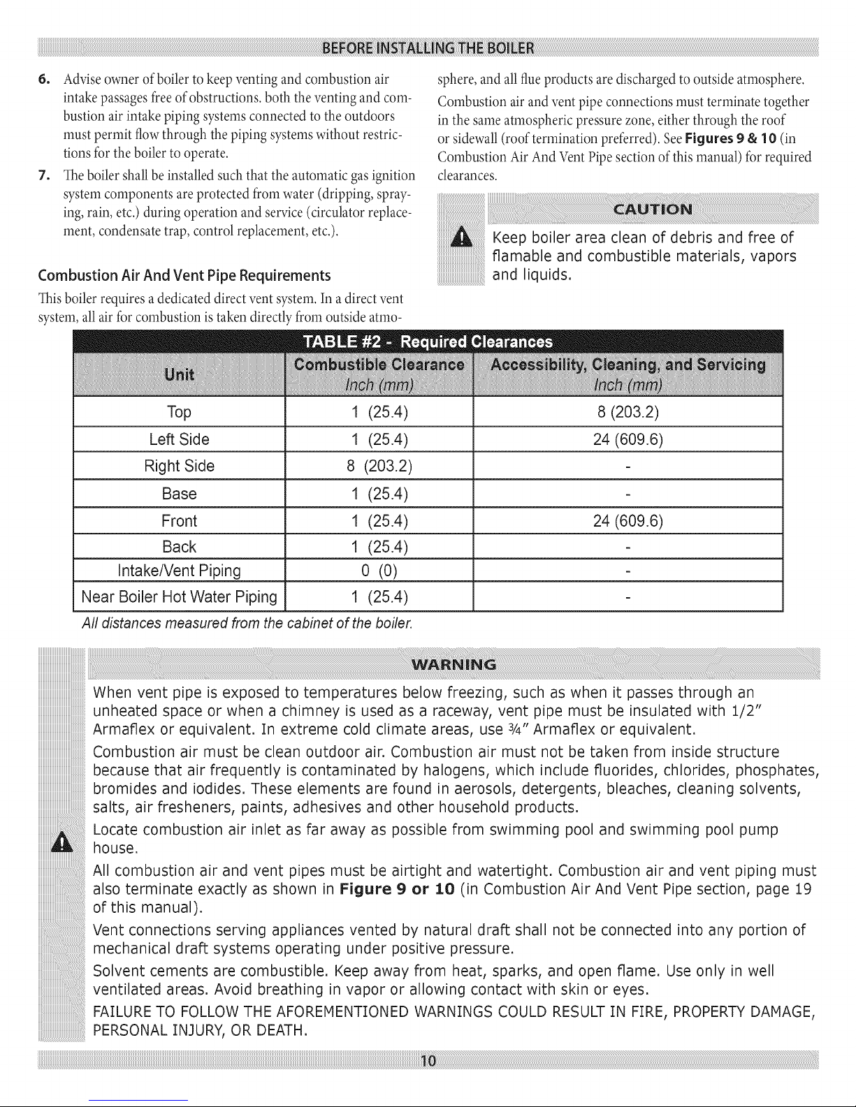
4. The clearances shown in Table #2 indicate required clearances.
A rninimurn 1" clearance rnust be rnaintained between corn-
bustible construction and each of the left, top and back surfaces
of the boiler. A rninimum 8" clearance is required on the right
side, to allow roorn for the inlet air pipe. An 18" clearance rnust
be rnaintained at a side where passage is required to access an-
other side for cleaning or servicing, inspection or replacernent
of any parts that norrnally rnay require such attention. Allow at
least 24" at the front and left side and 8" at the top for servicing.
No clearances are required to venting or cornbustion air intake
piping.
5. Equipment shall be installed in a location which facilitates the
operation of venting and cornbustion air intake piping systems
as described in this rnanual.
Page 10
6. Adviseownerofboilertokeepventingandcombustionair
intakepassagesfreeofobstructions,boththeventingandcorn-
bustionairintakepipingsystemsconnectedtotheoutdoors
rnustpermitflowthroughthepipingsysternswithoutrestric-
tionsfortheboilertooperate.
7. Theboilershallbeinstalledsuchthattheautomaticgasignition
systerncornponentsareprotectedfromwater(dripping,spray-
ing,rain,etc.)duringoperationandservice(circulatorreplace-
rnent,condensatetrap,controlreplacernent,etc.).
Combustion Air And Vent Pipe Requirements
This boiler requires adedicated direct vent systern. In a direct vent
systern, all air for cornbustion is taken directly frorn outside atrno-
Top 1 (25.4) 8 (203.2)
Left Side 1 (25.4) 24 (609.6)
Right Side 8 (203.2)
sphere,and all flue products are discharged to outside atmosphere.
Cornbustion air and ventpipe connections rnust terrninate together
in the sameatmosphericpressure zone, either through the roof
or sidewall(roof termination preferred). SeeFigures 9 & 10 (in
Combustion Air AndVentPipe sectionofthis manual) for required
clearances.
Keep boiler area clean of debris and free of
flamable and combustible materials, vapors
and liquids.
Base 1 (25.4)
Front 1 (25.4) 24 (609.6)
Back 1 (25.4)
Intake/Vent Piping 0 (0)
Near Boiler Hot Water Piping 1 (25.4)
All distances measured from the cabinet of the boiler.
When vent pipe is exposed to temperatures below freezing, such as when it passes through an
unheated space or when a chimney is used as a raceway, vent pipe must be insulated with :!./2"
Armaflex or equivalent. In extreme cold climate areas, use 3/4" Armaflex or equivalent.
Combustion air must be clean outdoor air. Combustion air must not be taken from inside structure
because that air frequently is contaminated by halogens, which include fluorides, chlorides, phosphates,
bromides and iodides. These elements are found in aerosols, detergents, bleaches, cleaning solvents,
salts, air fresheners, paints, adhesives and other household products.
Locate combustion air inlet as far away as possible from swimming pool and swimming pool pump
house.
All combustion air and vent pipes must be airtight and watertight. Combustion air and vent piping must
also terminate exactly as shown in Figure 9 or 10 (in Combustion Air And Vent Pipe section, page 19
of this manual).
Vent connections serving appliances vented by natural draft shall not be connected into any portion of
mechanical draft systems operating under positive pressure.
Solvent cements are combustible. Keep away from heat, sparks, and open flame. Use only in well
ventilated areas. Avoid breathing in vapor or allowing contact with skin or eyes.
FAILURE TO FOLLOW THE AFOREMENTIONED WARNINGS COULD RESULT IN FIRE, PROPERTY DAMAGE,
PERSONAL INJURY, OR DEATH.
Page 11
Condensate Drain Requirements
Condensate drain line to be pitched down to floordrain atamini-
rnurnof 1A"per foot.An external condensatepump (not furnished)
maybe used if floordrain isnot available.Thecondensate pump
must be designed for fluegas condensate application.
iiiiiiiiiiiiiiiiiiiiiiiiiiiiiiiiiiiiiiiiiiiiii_
:[.Condensatetrap bu,t ntothebo ler,an
external trap is not required and should not
2. Wood frame or blocks may be used to raise
the boiler to maintain drain pitch or to be
above external condensate pump reservoir.
3. There is a :[::[5 Volt AC receptacle provided
on the service switch junction box which is
located at the boiler right side, to provide
power for an external condensate pump (if
needed).
Foundation Requirements
Boilermust be placedon levelsurface.Boileris NOT to be installed
on carpeting.
iiiiiiiiiiiiiiiiiiiiiiiiiiiiiiiiiiiiiiiiiiiiii_
If boiler is not level condensate drain lines
will not function properly. Adjustable feet are
located on the boiler to makeup for minor
surface irregularities or tilt.
Wood frame or blocks may be used to raise
boiler to maintain drain pitch or to be above
external co ndensate pum p rese rv oir.
Removal of Existing Boiler From Common Vent System
When an existing boiler is rernoved from a common venting system,
the comrnon venting systern is likely to be too large for proper vent-
ing of the appliances remaining connected to it. At the time of re-
moval of an existing boiler, the following steps shall be followed with
each appliance rernaining connected to the common venting systern
placed in operation, while the other appliances rernaining connected
to the cornmon venting systern are not in operation.
1. Seal any unused openings in the comrnon venting systern.
2. Visually inspect the venting system for proper size and hori-
zontal pitch and deterrnine there isno blockage, or restrictions,
leakage, corrosion and other deficiencies which could cause an
unsafe condition.
3. In-so-far as is practical, close all building doors and windows
and all doors between the space in which the appliances remain-
ing connected to the common venting system are located and
other spaces of the building. Turn on clothes dryer and any ap-
pliance not connected to the common venting systern. Turn on
any exhaust fans, such as range hoods and bathroom exhaust, so
they will operate at maximum speed. Do not operate a summer
exhaust fan. Close fire darnpers.
4. Place in operation the appliance being inspected. Follow the
lighting instructions. Adjust therrnostat so appliances will oper-
ate continuously.
5. Test for spillage at the draft hood relief opening after 5minutes
of main burner operation. Use the flame of a match or candle,
or the smoke frorn acigarette, cigar or pipe.
6. After it has been deterrnined that each appliance remaining
connected to the common venting systern properly vents when
tested as outlined above, return doors, windows, exhaust fans,
fire place dampers, and any other gas-burning appliance to their
previous condition of use.
7. Any improper operation of the comrnon venting systern should
be corrected so the installation conforms with the National Fuel
Code, NFPA-54/ANSI -Z223.1 and/or the Natural Gas and
Propane Installation Code, CAN/CSA B149.1.. When resizing
any portion of the common venting systern, the comrnon vent-
ing system should be resized to approach the minimum size as
deterrnined using the appropriate tables in Chapter 13 of the
National Fuel Gas Code, NFPA-54/ANSI- Z223.1 and/or the
Natural Gas and Propane Installation Code, CAN/CSA B149.1.
The boiler should be placed to provide the most direct connections
to the combustion air, vent and systern piping as possible.
Place crated boiler as close to selected location as possible and
uncrate boiler. The uncrated boiler may be moved into position with
an appliance dolly or 2-wheel hand truck. The dolly or hand truck
should be inserted under the left hand side of the boiler. It is possible
to slide the boiler for a short distance on a smooth floor or surface.
Refer to manual section "locating the
boiler" (page 9 of this manual), for required
clearances for servicing and maintenance.
Page 12
When the installation of the boiler is for a new heating system, first
install all of the radiation units (panels, radiators, baseboard, or tub-
ing) and the supply and return mains. After all heating system piping
and components have been installed, make final connection of the
system piping to the boiler. A hot water boiler installed above radia-
tion level, or as required by the Authority having jurisdiction, must
be equipped with a low water cut off&vice. A periodic inspection
is necessary for flushing of float type devices, per low water cut off
manufacturers specific instructions.
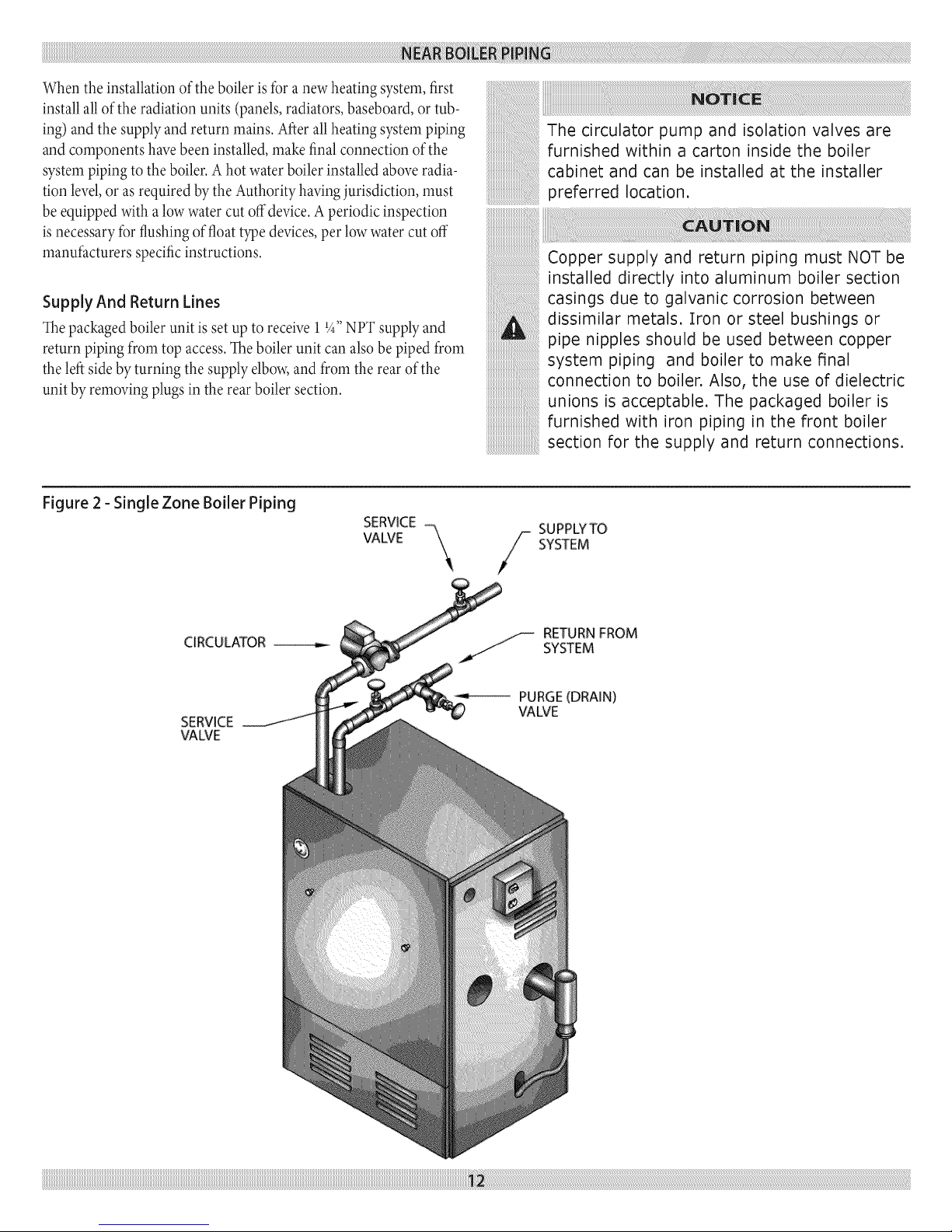
Supply And Return Lines
The packaged boiler unit is set up to receive 11_,,NPT supply and
return piping from top access. The boiler unit can also be piped from
the left side by turning the supply elbow, and from the rear of the
unit by removing plugs in the rear boiler section.
Figure 2 - Single Zone Boiler Piping
SERVICE -
The circulator pump and isolation valves are
furnished within a carton inside the boiler
cabinet and can be installed at the installer
preferred location.
Copper supply and return piping must NOT be
installed directly into aluminum boiler section
casings due to galvanic corrosion between
dissimilar metals. Iron or steel bushings or
pipe nipples should be used between copper
system piping and boiler to make final
connection to boiler. Also, the use of dielectric
unions is acceptable. The packaged boiler is
furnished with iron piping in the front boiler
section for the supply and return connections.
SUPPLYTO
CIRCULATOR
SERVICE
VALVE
VALVE
-SYSTEM
_.jj-- RETURN FROM
SYSTEM
PURGE(DRAIN)
VALVE
Page 13
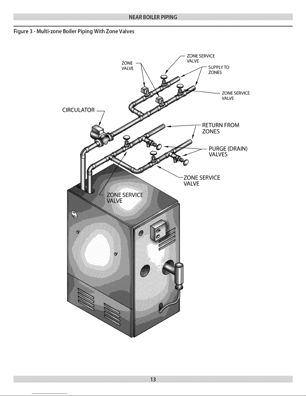
Figure 3 - Multi-zone Boiler Piping With Zone Valves
ZONE
\JAWE
CIRCU LATOR
ZONE SERVICE
VALVE
SUPPLYTO
ZONES
ZONESERVICE
VAWE
FROM
ZONES
PURGE (DRAIN)
VALVES
VALVE
Page 14
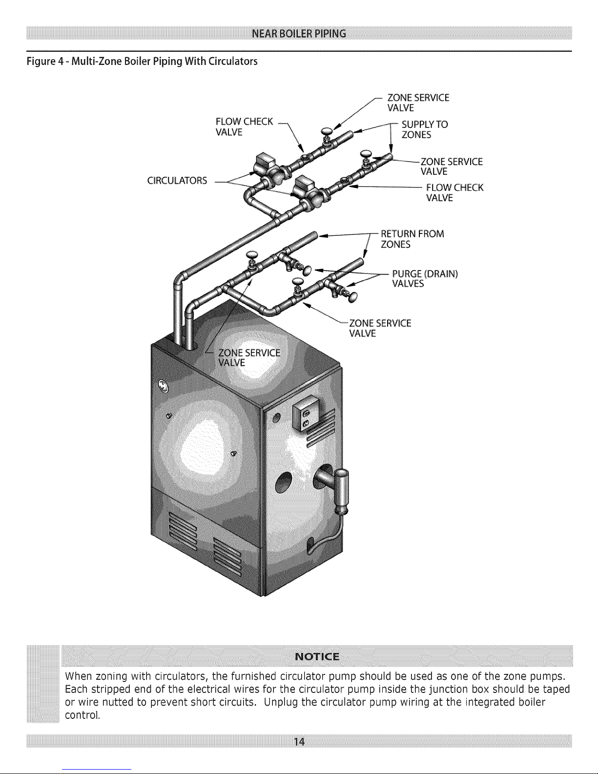
Figure4-Multi-ZoneBoilerPipingWithCirculators
FLOW CHECK
VALVE "\
CIRCULATORS
ZONE SERVICE
VALVE
SUPPLYTO
ZONES
_WE
FLOW CHECK
VALVE
RETURNFROM
ZONES
PURGE(DRAIN)
VALVES
SERVICE
VALVE
When zoning with circulators, the furnished circulator pump should be used as one of the zone pumps.
Each stripped end of the electrical wires for the circulator pump inside the junction box should be taped
or wire nutted to prevent short circuits. Unplug the circulator pump wiring at the integrated boiler
control.
Page 15
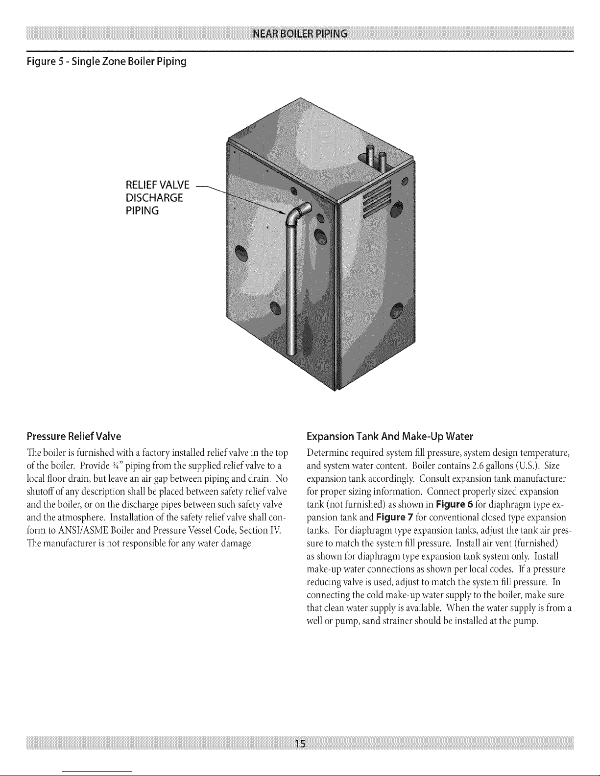
Figure5-SingleZoneBoilerPiping
DISCHARGE
PIPING
PressureReliefValve
Theboileris furnished with a factoryinstalled reliefvalvein the top
ofthe boiler. Provide3_,,piping frorn the supplied reliefvalveto a
localfloordrain, but leavean air gapbetweenpiping and drain. No
shutoffof any description shallbe placed betweensafetyreliefvane
and the boiler,oron the discharge pipes between such safetyvalve
and the atmosphere. Installationofthe safetyreliefvalveshall con-
forrn to ANSI/ASMEBoilerand Pressure VesselCode, Section IV.
Themanufacturer isnot responsiblefor aW water damage.
Expansion Tank And Make-Up Water
Deterrnine required systern fill pressure, systern design ternperature,
and systern water content. Boiler contains 2.6 gallons (U.S.). Size
expansion tank accordingly. Consult expansion tank manufacturer
for proper sizing information. Connect properly sized expansion
tank (not furnished) as shown in Figure 6 for diaphragm type ex-
pansion tank and Figure 7 for conventional closed type expansion
tanks. For diaphragm type expansion tanks, adjust the tank air pres-
sure to match the systern fill pressure. Install air vent (furnished)
as shown for diaphragm type expansion tank systern only. Install
make-up water connections as shown per local codes. If a pressure
reducing valve is used, adjust to match the systern fill pressure. In
connecting the cold make-up water supply to the boiler, make sure
that clean water supply is available. When the water supply is from a
well or pump, sand strainer should be installed at the pump.
Page 16

Figure 6 - Diaphragm Type Expansion Tank Piping
MANUAL FILL
VALVE
AUTOMATIC AIR
VENT _
3/4"xI/8" BUSHING _
3/4" TEE_
3/4" NIPPLE (FURNISHED
AND INSTALLED ON
PACKAGED BOILER)
3/4" STREET ELL*
COLD
WATER
FILL
FURNISHED IN
PARTS BAG.
DIAPHRAGM TYPE
EXPANSION TANK
COMBINATION QUICK FILL
VALVE, STRAINER, CHECK
VALVE AND PRESSURE
REDUCING VALVE
iiiiiiiiiiiiiiiiiiiiiiiiiiiiiiiiiiiiiiiiiiiiiiiiiiiiiiiiiiiiiiiiiiiiiiiiiiiiiiiiiiiiiiiiiiiiiiiiiiiiiiiiiiiiiiiiiiiiiiiiiiiiiiiiiiiiiiiiiiiiiiiiiiiiiiiiiiiiiiiiiiiiiiiiiiiiiiiiiiiiiiiiiiiiiiiiiiiiiiiiiiiiiiiiiiiiiiiiiiiiiiiiiiiiiiiiiiiiiiiiiiiiiiiiiiiiiiiiiiiiiiiiiiiiiiiiiiiiiiiiiiiiiiiiiiiiiiiiiiiiiiiiiiiiiiiiiiiiiiiiiiiiiiiiiiiiiiiiiiiiiiiiiiiiiiiiiiiiiiiiiiiiiiiiiiiiiiiiiiiiiiiiiiiiiiiiiiiiiiiiiiiiiiiiiiiiiiiiiiiiiiiiiiiiiiiiiiiiiiiiiiiiiiiiiiiiiiiiiiiiiiiiiiiiiiiiiiiiiiiiiiiiiiiiiiiiiiiiiiiiiiiiiiiiiiiiiiiiiiiiiiiiiiiiiiiiiiiiiiiiiiiiiiiiiiiiiiiiiiiiiiiiiiiiiiiiiiiiiiiiiiiiiiiiiiiiiiiiiiiiiiiiiiiiiiiiiiiiiiiiiiiiiiiiiiiiiiiiiiiiiiiiiiiiiiiiiiiiiiiiiiiiiiiiiiiiiiiiiiiiiiiiiiiiiiiiiiiiiiiiiiiiiiiiiiiiiiiiiiiiiiiiiiiiiiiiiiiiiiiiiiiiiiiiiiiiiiiiiiiiii_ii_ii_i_i_iiliiiliiiiiiiiiiiiiiiiliiiiiiiiiiiiiiiiiiiiiiiliiiiiiiiiiiiiiiiiiiiiiiliiiiiiiiiiiiiiiiiiiiiiiliiiiiiiiiiiiiiiiiiiiiiiliiiiiiiiiiiiiiiiiiiiiiiliiiiiiiiiiiiiiiiiiiiiiiliiiiiiiiiiiiiiiiiiiiiiiliiiiiiiiiiiiiiiiiiiiiiiliiiiiiiiiiiiiiiiiiiiiiiliiiiiiiiiiiiiiiiiiiiiiiliiiiiiiiiiiiiiiiiiiiiiiliiiiiiiiiiiiiiiiiiiiiiiliiiiiiiiiiiiiiiiiiiiiiiliiiiiiiiiiiiiiiiiiiiiiiliiiiiiiiiiiiiiiiiiiiiiiliiiiiiiiiiiiiiiiiiiiiiiliiiiiiiiiiiiiiiiiiiiiiiliiiiiiiiiiiiiiiiiiiiiiiliiiiiiiiiiiiiiiiiiiiiiiliiiiiiiiiiiiiiiiiiiiiiiliiiiiiiiiiiiiiiiiiiiiiiliiiiiiiiiiiiiiiiiiiiiiiliiiiiiiiiiiiiiiiiiiiiiiliiiiiiiiiiiiiiiiiiiiiiiliiiiiiiiiiiiiiiiiiiiiiiliiiiiiiiiiiiiiiiiiiiiiiliiiiiiiiiiiiiiiiiiiiiiiliiiiiiiiiiiiiiiiiiiiiiiliiiiiiiiiiiiiiiiiiiiiiiliiiiiiiiiiiiiiiiiiiiiiiliiiiiiiiiiiiiiiiiiiiiiiliiiiiiiiiiiiiiiiiiiiiiiliiiiiiiiiiiiiiiiiiiiiiiliiiiiiiiiiiiiiiiiiiiiiiliiiiiiiiiiiiiiiiiiiiiiiliiiiiiiiiiiiiiiiiiiiiiiliiiiiiiiiiiiiiiiiiiiiiiliiiiiiiiiiiiiiiiiiiiiiiliiiiiiiiiiiiiiiiiiiiiiiliiiiiiiiiiiiiiiiiiiiiiiliiiiiiiiiiiiiiiiiiiiiiiliiiiiiiiiiiiiiiiiiiiiiiliiiiiiiiiiiiiiiiiiiiiiiliiiiiiiiiiiiiiiiiiiiiiiliiiiiiiiiiiiiiiiiiiiiiiliiiiiiiiiiiiiiii!_!_!_¸_
Page 17
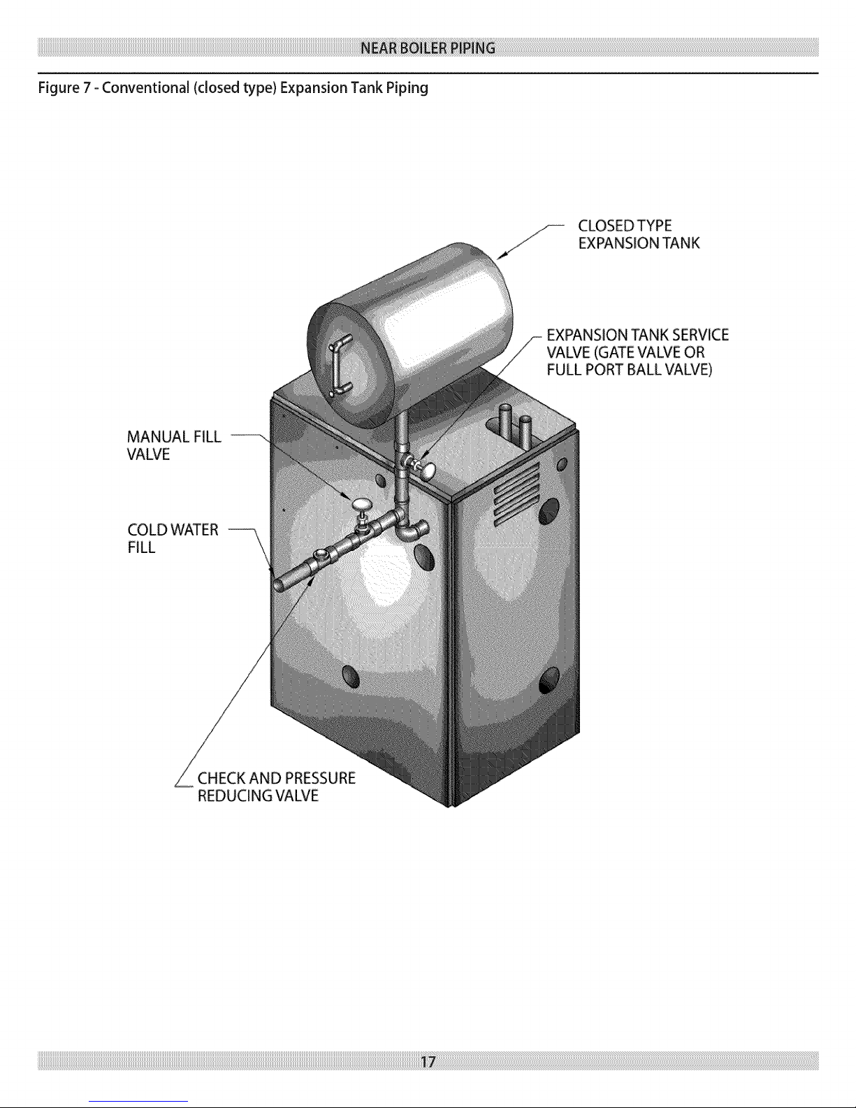
Figure 7 - Conventional (closed type) Expansion Tank Piping
MANUAL FILL
VALVE
CLOSEDTYPE
EXPANSION TANK
EXPANSION TANK SERVICE
VALVE (GATE VALVE OR
FULL PORT BALL VALVE)
COLD WATER
FILL
CHECK AND PRESSURE
REDUCING VALVE
Page 18

Figure8-CondensateDrainPiping
OPEN
DRAIN PIPETO
BE PITCHED DOWN
TO FLOOR DRAIN
ATA MINIMUM
THREADED NIPPLE (PVC)
(INSTALLED)
Condensate Drain Piping
The condensate trap isbuilt into the boiler, an external trap is not
required and should NOT be used.
Provide 1/2"PVC condensate drain and fittings. Condensate drain to
be pitched down to floor drain at a minimum of 1A"per foot.
Install furnished 1/2"PVC tee to overflow fitting as shown in Figure
8.
The 1/2"diacneter schedule 40 PVC or CPVC condensate drain and
pipe fittings must conform to ANSI standards and ASTM D 1785
or D2846. Schedule 40 PVC or CPVC cement and primer must
conform to ASTM D2564 or F493. In Canada, use CSA or ULC
certified schedule 40 PVC or CPVC drain pipe cement.
A condensate pump with a reservoir (not furnished) may be used
to remove condensate to a drain line (sanitary line) above boiler ifa
floor drain is not available or its in accessible.
_"-'-'\'\\'_""" "\\-- T01/4"PER FOOT
DRAIN
_"\_v_CONDENSATE
DRAIN
PVCTEE
1/2 SLIPxl/2 SLIPx1/2 NPT
FURNISHED IN PARTSBAG
Filling Condensate Trap With Water
On The Initial Start Up The Condensate Trap Must Be Manuall,_
Filled With Water.
The following are the steps required to initially fill the condensate
trap for start up, these steps are only required at the initial start up or
ifmaintenance requires draining of the condensate trap:
1. Disconnect the vent condensate drain line from the bottom of
the vent tee on the boiler.
2. Pour about 1cup of coldtapwater into the ventdrain line with
aproper funnel.
3. Excesswatershould go through the overflowand out through
the condensatedrain line.Verifyproper operation of the drain
line (or external condensate pump if used).
4. Reinstall the vent drain line.
Page 19

Chilled Water Piping
The boiler, when used in connection with a refrigeration system,
must be installed so the chiller medium is piped in parallel with the
boiler with appropriate valves to prevent the chilled medium frorn
entering the boiler.
Connections And Termination
Provisions for combustion and ventilation air must be in accordance
with section, Air For Combustion and Ventilation, of the National
Fuel Gas Code,ANSI 2223.1/NFPA54, or Sections 8.2, 8.3 or 8.4 of
National Gas and Propane Installation Code, CAN/CGA-B 149.1, or
applicable provisions of the local building code.
These boilers require a dedicated direct vent system. All air for com-
bustion is taken directly from outdoors through the combustion air
intake pipe. All flue products are discharged to the outdoors through
the vent pipe.
1. Refer to Combustion Air And Vent Pipe section that follows,
also see Figures 9 & 10 for combustion air and vent pipe
roof and sidewall termination. (Roof termination is preferred)
Combustion air and vent pipes must terminate together in same
atrno spheric pressure zone as shown. Construction through
which vent and air intake pipes may be installed is a maximum
24 inches, minimum 1A"thiclca_ess.
2. Combustion air and vent pipe fittings must conform to
American National Standards Institute (ANSI) standards and
American Society for Testing and Materials (ASTM) standards
D1784 (schedule-40 CPVC), D1785 (schedule-40 PVC), D2665
(PVC-DWV), D2241 (SDR-21 and SDR-26 PVC), D2661 (ABS-
DWV), or F628 (schedule-40 ABS). Pipe cement and primer
must conform to ASTM standards D2564 (PVC) or D2235
(ABS).
In Canada construct all combustion air and vent pipes for this unit
of CSA or ULC certified schedule-40 CPVC, schedule-40 PVC,
PVC-DWV or ABS-DWV pipe and pipe cement. SDR pipe is NOT
approved in Canada.
3. Combustion air and vent piping connections on boiler are sized
for 2" pipe. Any pipe size change (to 3") must be made outside
of the boiler casing in a vertical run of pipe to allow for proper
drainage ofvent condensate. Due to potential for flue gas tem-
peratures over 155°F, the first five (5) feet of vent pipe must be
CPVC, the remaining vent pipe can be PVC. If any elbows are
employed within the first 5 feet of vent, they must be CPVC too.
Two (2)- 30" pieces of 2" CPVC pipe are furnished with the
boiler.
The boiler piping system of a hot water boiler connected to heat-
ing coils islocated in air handling units where they may be exposed
to refrigerated air circulation must be equipped with flow control
valves or other automatic means to prevent gravity circulation of the
boiler water during cooling cycle.
The transition from 2" pipe to 3" pipe must be
made in a vertical run.
ASTM F891 *
ASTM D2665 **
ASTM D1785 **
ASTM D2241 **
ASTM D2846 **
ASTM F441 **
ASTM F442 **
ASTM D2661 ***
ASTM F628 ***
UL-1738
ULC $636
* Allowable temperatures based on Classifications covered inASTM
D4396 [Deflection Temperatures under Load (264 psi) (1819KPa)].
** Allowable temperatures based on Classifications covered in ASTM D1784
[Deflection Temperatures under Load (264 psi) (1819KPa)].
*** Allowable temperatures based on Classifications covered inASTM D3965
[Deflection Temperatures under Load (264 psi) (1819KPa)].
Page 20

4. Combustion air and vent piping lengths:
2 FEET 21 FEET 15 FEET 92 FEET
1 l l 112FEET
The first 5 ft. of"TOTAL EQUIVALENT LENGTH" of vent piping
run must be 2" CPVC:
Thelengthofpipe iscounted frorn the boilerjacket (air intake pipe)
or fromvent tee (ventpipe) the termination isnot counted toward
the "TotalEquivalent Length".
For additional elbows,reduce the maximum vent length as shown:
• 2" 90°elbow-1 1/2ft.per additional elbow.
• 3" 90°elbow- 3ft. per additional elbow.
N. Cornbustion air and vent piping to be pitched back to boiler at
minimum 1A"per ft. (21 rnrn/rn) from intake and vent terminals
so that all moisture in combustion air and vent piping drains to
boiler. Pipes must be pitched continuously with no sags or low
spots where moisture can accumulate and block the flow of air
or flue gas. Combustion air and vent pipes must be airtight and
watertight.
5. Consideration for the following should be used when
determining an appropriate location for termination of
combustion air and vent piping.
• Comply with all clearances required as stated in paragraph 7.
Termination should be positioned where itwill not be
subjected to potential damage by foreign objects, such as
stones, balls, etc..
Termination should be positioned where vent vapors are not
objectionable.
Put vent on a wall away from the prevailing winter wind.
Locate or guard the vent to prevent accidental contact with
people or pets.
Terminate the vent above normal snowline. Avoid locations
where snow may drift and block the vent. Ice or snow may
cause the boiler to shut down ifthe vent becomes obstructed.
Under certain conditions, fluegaswill condense, forming
moisture, and may becorrosive. In suchcases,steps should
be taken to prevent building materials at the vent from being
damaged by exhaust of fluegas.
• Vent shallnot terminate whereit may causehazardous frost or
iceaccumulations on adjacent property surfaces.
o
The venting system shall terminate at least 3 ft. (0.9m) above
any forced air inlet (except the boiler's combustion air inlet)
within 10 ft.(3m). The venting system shall terminate at least 12
in. from any air opening into any building. The bottom of the
vent shall be located at least 12in. above grade. Termination
of the vent shall be not less than 7ft. (2.1m) above an adjacent
public wall<way or paved driveway. The vent terminal shall
not be installed closer than 3 ft. from the inside corner of an
Lshaped structure. Termination of the vent should be kept at
least 3 ft. away from vegetation.
USA onl.>.The venting system shall terminate at least 4 ft.
horizontally from, and in no case above or below, unless a
4 ft. (1.22m) horizontal distance is maintained, from elec-
tric meters, gas meters, regulators, and relief equipment.
Canada only_. The venting system shall terminate at least 6 ft.
(1.83m) horizontally from, an in no case above or below, unless
a 6 ft. (1.83m) horizontal distance is maintained, from electric
meters, gas meters, regulators, and relief equipment.
• Termination should be positioned where vent vapors willnot
damage plants/shrubs or air conditioning equipment.
• Termination should be positioned so that it willnot be effected
by wind eddy,air born leaves,snow, or recirculatedfluegases.
Page 21

Figure 9 - Roof Vent / intake terminations
8" MINIMUM
VERTICAL SEPAPJ_.T[ON
BETWEEN COMBUSTION
AIR INTAKE AND VENT
MAiNTAiN 12" MiNiMUM _//
CLEARANCE ABOVE HIGHEST
ANTICIPATED SNOW LEVEL
USA- 12" (300ram)
Canada - 18" (450ram)
Vent shall not terminate with 6 ft. (1.8m) of a mechanical
air-supply inlet to any building.
Vent shall not terminate above a regulator within 3 ft. (900
mm) horizontally of the vertical centerline of the regulator
vent outlet to a maximum vertical distance of 15ft (9.5m).
Vent shall not terminate within 3 ft. (900mm) ofa window
or door that can be opened in any building, or any non-
mechanical air-supply inlet to any building, or ofthe
combustion air inlet of any other appliance.
Vent shall not terminate underneath a veranda, porch or
deck unless, (a) the veranda, porch or deck is fully open
on a minimum of two sides beneath the floor, and (b) the
distance between the top of the vent termination and the
underside of the veranda, porch or deck is greater than 1 ft.
(300ram).
Page 22

Figure 10A - Side Wail Vent / Intake terminations - Less Than 12" Clearance Above Grade
LessThan 12" Clearance
Figure 10B - Side Wail Vent / Intake Terminations - 12" Or More Clearance Above Grade
Page 23

Figure11-CombustionAirandVentPiping
2° (S&Smm) COMBUSTION A_R
INTAKE P{PiNG ....._.
2" 1508ram) CPVC VENT PIPING ',
(FURNiSHED) _°-,_,,__
2" (50,8mm} CPVC COUPLING
(FURNISHED
5'
1,52m
VENT/_NTAKE
TERMiNATiONS
2* (50,Bmm) DIAMETER VENT AND
COMBUSTION AiR iNTAKE
P_PING -
15' (4,57m)MAXIMUM LENGTH TOTAL
W_TH 4 ° 90 ° ELBOWS FOR K£0 - 100
20' (&lOre) MAXIMUM LENGTH TOTAL WITH
4 - 90 ° ELBOWS FOR K90 - 75 AND Kg0 - 50
2' (61 m) MINIMUM LENGTH TOTAL
WiTH 4 - 90° ELBOWS FOR ALL
EXHAUST TEE
(FURNISHED_
3" (7&2ram) COMBUSTION
INTAKE PiPiNG
2" (50 8mm) CPVC VENT PIPmNG
(FURNISHED)
2" (50 8mm) CPVC COUPLING
(FURNISHED)
TERM{NATIONS
3" (76.2mm) VENT PiPiNG
TRANSiTiON FITTING
//-- 2" (50,8ram) O TO 3" (76,2mm) _ iN
.,,./// 3" (76,2mm), D AMETER VENT' AND
5' 100' (3&48m) MAXIMUM LENGTH TOTAL
1,52m WiTH 4 - 90_ ELBOWS
. VERTICAL RUN
COMBUSTION AiR iNTAKE PtPING
FOR K90 - 100
80' (24,38m) MAXIMUM LENGTH TOTAL
W_TH 4 _ 90° ELBOWS
15' (6,10m) MINIMUM LENGTH TOTAL
WITH 4 - 90_ ELBOWS
FOR t<90- 75 AND K90 - 50
20' (6o10m) MINIMUM LENGTH TOTAL
WITH 4 - 90 ° ELBOWS
TRANSITION FITTING
2" (50,Bmm) O TO 3" (76,2mm) O iN
VERTICAL RUN
EXHAUST TEE
(FURNISHED)
Page 24

Installation
1. Attach cornbustion air intake piping to supplied Fernco 2" cou-
pling on mixer. Attach vent piping to furnished 2" CPVC vent
tee on draft inducer outlet.
2. Worldng from the boiler to the outside, cut pipe to required
length(s).
3. Deburr inside and outside of pipe.
4. Charnfer outside edgeof pipe for better distribution of primer
and cement.
5. Clean and dry all surfacesto be joined.
6. Check dry fitof pipeand mark insertion depth on pipe.
It is recommended that all pipes be cut,
prepared, and pre-assembled before
permanently cementing any joint.
7.
After pipes have been cut and pre-assernbled,apply cement
primer to pipefitting socketand end ofpipe to insertion rnark.
Quicklyapply approvedcernentto end of pipe and fitting
socket(overprimer). Apply cernent in light,uniform coaton
the inside of socketto prevent buildup of excesscement. Apply
second coat.
8. While cement isstill wet, insert pipe into socket with 1Aturn
twist. Be sure pipe is fully inserted into fitting socket.
9. Wipe excess cement from joint. A continuous bead of cernent
will be visible around perirneter of a properly rnade joint.
10. Handle pipe joint carefully until cement sets.
11. Support combustion air and vent piping a minimum of
every 5 feet using pre-forrned rnetal hanging straps. Do not
rigidly support pipes. Allow rnovernent due to expansion and
contraction.
12. Slope horizontal portion of cornbustion air and vent pipes
toward boiler a minimum of 1A"per linear ft. (2h-nrn/rn) with
no sags between hangers.
13° Use appropriate rnethods to seal openings where vent and
combustion air pipes pass through roof or side wall.
Check Gas Supply
The gas pipe to your boiler rnust be the correct size for the length
of run and for the total Btuper hour input of all gas utilization
equipment connected to it. See Table #:3 for the proper size (next
page). Be sure your gas line cornplies with local codes and gas
cornpany requirernents.
The boiler and its indMdual shutoff valve rnust be disconnected
from the gas supply piping systern during aW pressure testing of
that systern at test pressures in excess of 1/2psig (3.5kpa).
The boiler rnust be isolated frorn the gas supply piping systern by
closing its indMdual rnanual shutoff valve during any pressure
testing of the gas supply piping systern at test pressures equal to or
less than 1/2psig (3.50ka).
MAXIMUM GAS SUPPLY
PRESSURE
MINIMUM GAS SUPPLY
PRESSURE
Connecting The Gas Piping
Refer to Figure 12 (on following page) for the general layout at the
boiler. It shows the basic fittings you will need. The gas line enters
the boiler frorn the right side jacket panel. The boiler rnay receive
the gas supply pipe through the left side, or rear jacket panel by
relocating the gas valve connector and pipe assernbly. The boiler
is equipped with a1/2"NPT connection on the gas valve for supply
piping. The following rules apply:
10" w.c. 14" w.c.
4" w.c. 10" w.c.
1. Use only those piping rnaterials and joining rnethods listed
as acceptable by the authority having jurisdiction, or in the
absence of such requirements, by the National Fuel Gas Code,
ANSI Z223.1/NFPA 54 and or the Natural Gas and Propane
Installation Code, CAN/CSA B149.1.
2. Use pipe joint cornpound suitable for liquefied petroleurn gas
on rnale threads only.
3. Use ground joint unions.
4. Install a sediment trap upstrearn of gas controls.
5. Use two pipe wrenches when rnaldng the connection to the gas
valve to keep it frorn turning.
6. Install arnanual shutoff valve in the vertical pipe about 5 feet
above floor.
7. Tighten alljoints securely.
8. Propane gasconnections should onlybe rnade by alicensed
propane installer.
9. Two stageregulation should be used by the propane installer.
10. Propane gas piping should be checkedout by thepropane
installer.
Page 25

Checking The Gas Piping
The boiler and its gas connection must be leak tested before placing
the boiler in operation. Open the manual shutoff valve. Test for leaks
by applying soap suds (or a liquid detergent) to each joint. Bubbles
forming indicate leak. CORRECT EVEN THE SMALLEST LEAK
AT ONCE.
Never use a match or open flame to test for
leaks.
20
40
60
20 131,000 216,000 189,000 393,000
40 90,000 145,000 129,000 267,000
60 72,000 121,000 103,000 217,000
* Outside diameter
Figure 12 - Gas Piping
92,000 190,000 350,000 625,000
63,000 130,000 245,000 445,000
50,000 105,000 195,000 365,000
818" 3/4" 1/2" 3/4"
_///S GAS SUPPLY
PIPING
MANUAL
SHUT=OFF
VALVE
SEDIMENT
TRAP
GROUND JOINT
UNION
Page 26

iiiiiiiiiiiiiiiiiiiiiiiiiiiiiiiiiiiiiiiiiiiiii_
iiiiiiiiiiiiiiiiiiiiiiiiiiiiiiiiiiiiiiiiiiiiiii
iiiiiiiiiiiiiiiiiiiiiiiiiiiiiiiiiiiiiiiiiiiiiii
iiiiiiiiiiiiiiiiiiiiiiiiiiiiiiiiiiiiiiiiiiiiii_
iiiiiiiiiiiiiiiiiiiiiiiiiiiiiiiiiiiiiiiiiiiiiii
iiiiiiiiiiiiiiiiiiiiiiiiiiiiiiiiiiiiiiiiiiiiiii
All electrical work must conform to local codes as well as the
National Electrical Code, ANSI/NFPA70, and/or the Canadian
Electrical Code, Part 1,CSA C22.1, Electrical Code.
Electric Power Supply
Prior to making any line Voltage connections, service switch at
boiler should be in the OFF position and the power turned OFF at
the fuse box.
Turn off electrical power at fuse box before
making any line voltage connections. Follow
local electrical codes.
Run a separate 120Voltcircuit from aseparate over current protec-
tion devicein the electricalservice entrance panel. Thisshould be a
15amperecircuit. A service switchhas been pre-wired and located
on the exterior boilerjacket. See Figure 13 for diagracnshowing
locationof serviceswitchjunction box and power supply connection
points. Connect black(hot) leadfrom the power supplyto either
ofthe unused brassscrewsonthe service switch.Connect the white
(neutral) lead from the power supplyto the white screwon the ser-
viceswitch. Connect the green (ground) lead fromthe power supply
to the ground (green)screw on the serviceswitch.Thereceptacleon
the serviceswitchis alwayspoweredregardlessofwhether the switch
is ON or OFF,and could be used asa power supplyfor an external
condensatepump if one is used.
Theboiler,when installed, must be electricallygrounded in accor-
dancewith the requirements ofthe authority having jurisdiction or,
in the absenceof such requirements, with the National Electrical
Code, ANSI/NFPA-70and/or the Canadian Electrical Code Part 1,
CSA-C22.1,ElectricalCode.
Run a 14gaugeor heavier copper wire from the boilertoa grounded
connection in the servicepanel or a properlydriven and electrically
_._nr_ai f.t_au_d'. Pump Wiring
SeeFigure 13 (followingpage)for service switchjunction box and
circulatorpump fieldwiring connections. A5feetwiring harness
with flexiblemetal conduit is supplied to connect the circulator
pump to the service switchjunction box. Ifthe two 120Voltcircula-
tor wire terminals inside the junction box are not used, pleaseleave
the two wire nuts to prevent the short circuit.
LABEL ALL WIRES PRIOR TO DISCONNECTION
WHEN SERVICING CONTROLS. WIRING ERRORS
OPERATION. VERIFY PROPER OPERATION AFTER
CAN CAUSE IMPROPER AND DANGEROUS
SERVICING.
Corners and alcoves Behind doors
Concealed pipes
Concealed pipes or ducts
Fireplace
TV sets
Stairwells- drafts
Unheated rooms on
other side of wall
Radios
Lamps
Direct sunlight
Kitchens
Install Your Thermostat
The thermostat location has an important effect on the operation of
your boiler system. BE SURE TO FOLLOW THE INSTRUCTIONS
INCLUDED WITH YOUR THERMOSTAT.
Locate the thermostat about five feet above the floor on an inside
wall. It may be mounted directly on the wall or on a vertical mount-
ed outlet box. It should be sensing average room temperature.
Avoid the Following:
Set heat anticipator at 0.7 amps. Connect 24 Volt thermostat leads
to the two(2) yellow wires located in service switch junction box,
located on outer jacket of boiler. See Figure 13 for service switch
junction box and thermostat field wiring connections.
iiiiiiiiiiiiiiiiiiiiiiiiiiiiiiiiiiiiiiiiiiiiiiiiiiiiiiiiiiiiiiiiiiiiiiiiiiiiiiiiiiiiiiiiiiiiiiiiiiiiiiiiiiiiiiiiiiiiiiiiiiiiiiiiiiiiiiiiiiiiiiiiiiiiiiiiiiiiiiiiiiiiiiiiiiiiiiiiiiiiiiiiiiiiiiiiiiiiiiiiiiiiiiiiiiiiiiiiiiiiiiiiiiiiiiiiiiiiiiiiiiiiiiiiiiiiiiiiiiiiiiiiiiiiiiiiiiiiiiiiiiiiiiiiiiiiiiiiiiiiiiiiiiiiiiiiiiiiiiiiiiiiiiiiiiiiiiiiiiiiiiiiiiiiiiiiiiiiiiiiiiiiiiiiiiiiiiiiiiiiiiiiiiiiiiiiiiiiiiiiiiiiiiiiiiiiiiiiiiiiiiiiiiiiiiiiiiiiiiiiiiiiiiiiiiiiiiiiiiiiiiiiiiiiiiiiiiiiiiiiiiiiiiiiiiiiiiiiiiiiiiiiiiiiiiiiiiiiiiiiiiiiiiiiiiiiiiiiiiiiiiiiiiiiiiiiiiiiiiiiiiiiiiiiiiiiiiiiiiiiiiiiiiiiiiiiiiiiiiiiiiiiiiiiiiiiiiiiiiiiiiiiiiiiiiiiiiiiiiiiiiiiiiiiiiiiiiiiiiiiiiiiiiiiiiiiiiiiiiiiiiiiiiiiiiiiiiiiiiiiiiiiiiiiiiiiiiiiiiiiiiiiiiiiiiiiiiiiiiiiiiiiiiiiiiiiii¸i_ii!ii_!!_!i_!i_!i_!i_!i_!i_!i_!i_!i_!i_!i_!i_!i_!i_!i_!i_!i_!i_!i_!i_!i_!i_!i_!i_!i_!i_!i_!i_!i_!i_!i_!i_!i_!i_!i_!i_!i_!i_!i_!i_!i_!i_!i_!i_!i_!i_!i_!i_!i_!i_!i_!i_!i_!i_!i_!i_!i_!i_!i_!i_!i_!i_!i_!i_!i_!i_!i_!i_!i_!i_!i_!i_!i_!i_!i_!i_!i_!i_!i_!i_!i_!i_!i_!i_!i_!i_!i_!i_!i_!i_!i_!i_!i_!i_!i_!i_!i_!i_!i_!i_!i_!i_!i_!i_!i_!i_!i_!i_!i_!i_!i_!i_!i_!i_!i_!i_!i_!i_!i_!i_!i_!i_!i_!i_!i_!i_!i_!i_!i_!i_!i_!i_!i_!i_!i_!i_!i_!i_!i_!i_!i_!i_!i_!i_!i_!i_!i_!i_!i_!i_!i_!i_!i_!i_!i_!i_!i_!i_!i_!i_!i_!i_!i_!i_!i_!i_!i_!i_!i_!i_!i_!i_!i_!i_!i_!i_!i_!i_!i_!i_!i_!i_!i_!i_!i_!i_!i_!i_!i_!i_!i_!i_!i_!i_!i_!i_!i_!i_!i_!i_!i_!i_!i_!i_!i_!i_!i_!i_!i_!i_!i_!i_!i_!i_!i_!i_!i_!i_!i_!i_!i_!i_!i_!i_!i_!i_!i_!i_!i_!i_!i_!i_!i_!i_!i_!i_!i_!i_!i_!i_!i_!i_!i_!i_!i_!i_!i_!i_!i_!i_!i_!i_!i_!i_!i_!i_!i_!i_!i_!i_!i_!i_!i_!i_!i_!i_!i_!i_!i_!i_!i_!i_!i_!i_!i_!i_!i_!i_!i_!i_!i_!i_!i_!i_!i_!i_!i_!i_!i_!i_!i_!i_!i_!i_!i_!i_!i_!i_!i_!i_!i_!i_!i_!i_!i_!i_!i_!i_!i_!i_!i_!i_!i_!i_!i_!i_!i_!i_!i_!i_!i_!i_!i_!i_!i_!i_!i_!i_!i_!i_!i_!i_!i_!i_!i_!i_!i_!i_!i_!i_!i_!i_!i_!i_!i_!i_!i_!i_!i_!i_!i_!i_!i_!i_!i_!i_!i_!i_!i_!i_!i_!i_!i_!i_!i_!i_!i_!i_!i_!i_!i_!i_!i_!i_!i_!i_i_i¸_¸_¸_
Page 27

Figure 13 - Field Wiring Connections
f
BOILER
WIRING
tN J-BOX
120 VOLT
CIRCULATOR BK= BLACK
W = WHITE
y G = GREEN
24 VOLT
THERMOSTATW NEUTRALq
Y= YELLOW
// SERVICESWITCH
EIELD WIRING CONNECTIONS
BK HOT _-120 VOLTS
!
J
SERVICE SWITCH
JUNCTION BOX
Page 28

Figure 14 - D - Schematic Wiring Diagram
E
,, >- (-9 r_ _ "
m
n u n n
cD _ cD _
m LU
UJ _ LT_
0 0
0 0 _
_8
(-9
s9
_<
Ssd
_S£S
£S8S
85E
o
8SSS
_$ss
s_g
_Ss<
<
S
o
!
! I 0
! I-!
_] I ii
.r ! I !
i
_- | i i
! i !
if any of the 0riginal wire as supplied with this appliance must be replaced, it must be replaced with type
150° CTherm0piastic wire or its equivalent
Page 29

Figure 15 - E- Ladder Wiring Diagram
120 VOLT
POWER SUPPLY,/_X
L1 ,,
HOT' L2
I
ON/OFF SWITCH__f _BLK. WHT
P7-1
2K1 P4-1 / ",
_I )) ------m _ .......
1K1 P10-I CIRCULATOR MOTOR
P5-1 ' " ' ">
DRAFT INDUCER P10-2
HOT SURFACE IGNITER
5K1 P6-1 P12-1 P12-2 P6-2 5K2
l_-->>--4_) (( II ]
120 P1-3
P1-1 _'t_ TRANSFORMER
_L
P4-3
P7-3
<(
P5-3
P2-1
"_' "_>>_-_ __-2
CASTING TEMPERATURE
SAFETY SWITCH GAS VALVE I
(MANUAL RESET) VR8205A /
1 P3-5 P9-3 _ P9-2 P3-2
¥' " ' I I
II ELECTRONIC
G) I_ _ I -_ LOGIC&TIMERS --
Q 1__¢1DIFFERENTIALAIR INDICATOR LIGHTS
O J _ PRESSURE SWITCH _ -- _-_I
£'P3 3 U POWER .'_KI
"ro-o __ O PURGE
;P3-6 O IGNITER
P3-9 AQUASTAT O FLAME " I
HIGH LIMIT O VALVE _t__ 1
P7-2
_- TEMPERATURE
i _- CONTROL lO13-1oCONTROL
I
P3-7
: P3-4
THERMOSTAT
BLOWER
SAFETY SWITCH
POWER SUPPLY. PROVIDE
DISCONNECT MEANS AND
OVERLOAD PROTECTION AS
REQUIRED USE ONLY COPPER
WIRE BETWEEN DISCONNECT
AND THE UNIT
NOTE: "P" LABEL REFERENCE
LOCATION OF CONNECTOR PLUG
BETWEEN SCHEMATIC AND
LADDER DIAGRAM
* CAUTION: RECEPTACLE IS LIVE WHEN
BOILER SWITCH IS OFF
--_>--- REFERENCES PLUG CONNECTION
Page 30

Thissection provides abrief description of the keycontrolsand
accessoriesfound in this boiler.
Seethe Troubleshooting section (page47 of the ofthis installation
manual) for detailed sequencesofoperation andtroubleshooting
procedures.Seethe RepairPartsManual for locationsof allcontrol
components and accessoriesdescribed.
Integrated Boiler Control (IBC)
The Integrated Boiler Control (IBC) is a microprocessor based
controller for a high efficiency gas boiler that monitors all safety
controls and which controls the operation of the combustion air
blower, circulator pump, burner, and a combination hot surface
igniter/flame sensor. This controller is not intended for use with a
vent damper. This controller is mounted on the control panel inside
of the boiler and contains five (5) diagnostic indicator lights.
Gas Control Valve
The electrically controlled 24 Volt Honeywell Model VR8205
Combination Gas Control Valve is designed to meet the
requirements for use with hot surface ignition systems found in this
boiler. The valve is piped to the gas/air mixer.
Hot Surface Igniter
The 120Volt Hot Surface Igniter heats up to 1800 °F to initiate com-
bustion of the gas in the burner. The igniter is mounted next to the
burner through the gas/air mixer. The igniter also serves as a means
for proving the main burner flame by flame rectification. In the event
of a lack of flame signal on three (3) consecutive trials for igni-
tion, the IBC will loci<out. The "VALVE"and "FLAME" diagnostic
indicator lamps (lamp "D" and "E" on the IBC, See Figure 16) will
blink indicating the failure mode as a lack of flame signal. The IBC is
manually reset from lockout by either removing and reestablishing
the thermostat's call for heat, or by turning the service switch OFF,
then back ON.
High Limit Aquastat Control
TheHighLimitAquastat Control determines the maximum boiler
watertemperature and alsoprovides a means for protecting the
boilerand heating systemfrom unsafe operating conditions which
coulddamagethe boiler. Theaquastat ismounted in the 1/2"NPT
controlwelland 3_,,xl/2,,bushing on the top of the front boiler
section atthe hot wateroutlet. The aquastatis tied in with the
IBCand is factory set at 180°Fwater temperature. Thehigh limit
setpoint isfieldadjustableand maybe set anywherebetween 100
°Fand 200 °E Thefield setpoint adjustment for each installation
depends on heating systemrequirements. Theaquastat automatically
resetswhen the boilerwatertemperature decreases(5-30°F
adjustabledifferential).Thedifferentialcanbe adjusted with the
(white) DifferentialAdjustment Wheel on the aquastat andgivesthe
fexibility for boileroperation. The largerthe differential,the longer
the run cycleofthe boiler.
The maximum setpoint of the Aquastat must
not exceed 200 °F.
Draft Inducer Temperature Safety Switch
The Draft Inducer Temperature Safety Switch is a disc thermostat
(180 °F setpoint) located on the induced draft fan outlet port. The
switch protects the inducer and vent pipe from a potential high
temperature condition for the discharging flue gases. This condition
would typically be a result of higher aquastat setting or over firing.
The temperature safety switch automatically resets when the higher
aquastat setting or over firing. The temperature safety switch
automatically resets when the vent temperature decreases. (15 °F
switch differential).
Casting Temperature Safety Switch
In the event of lack of or loss of water in the boiler, the Casting
Temperature Safety Switch (300 °F setpoint) installed on the top
of the aluminum boiler section shuts off the boiler by shutting off
power to the Integrated Boiler Control (IBC) and causes the Power
Indicator Light to go out. This fault requires manual reset of the
casting temperature safety switch to restart the boiler. Verify that
the boiler is properly filled with water before resetting this switch.
WARNING=Never run cold water into a hot empty boiler.
Differential PressureAir Proving SwRch/BIocked Vent
Safety Shutoff
All 90 SeriesHot Water Boilerscomeequipped with either one (100
Series)or two (200 Series)diaphragm-type differentialpressure
switches.Thedifferentialpressure switchmonitors air flowby
sensingthe differentialpressure measured in inchesof water ("w.c.).
Thepressureswitch contactsclosewhen the draft inducer is running.
Theclosedswitchprovesthere is adequateair flowfor combustion.
Thepressureswitch shutsoffthe main burner if the differential
pressure isinadequate due to a blockedvent pipe, a blocked air
intake,blocked boilersections, or a blockeddraft inducer. After
five(5)minutes of lackofadequate differentialpressure, the IBC
willlockout and the "Purge"indicator light willblink,indicating a
failure to prove adequate combustion air floworflue gas flow.The
IBCwill beautomaticallyreset after fifteen(15)minutes or can be
manually resetfrom loci<outby (a) removing and reestablishingthe
thermostat callfor heat or (b) byturning the serviceswitchOFFand
back ON again.Ifthe boiler cannot be restored to normal operating
conditions byresetting the control, contact a quallified service
agencyto checkthe heat exchangerflue-waysforblockage.
Page 31

Draft Inducer
The draft inducer (blower) provides a means for pulling combustion
air into and through the mixer, the burner, the flue ways of the
cast aluminum boiler sections and the flue adapter before being
discharged through the vent piping to the outdoors. See applicable
sections for proper sizing and installation of combustion air and vent
piping in this manual.
Circulator Pump
Everyforcedhot water systernrequiresatleastone circulating purnp.
Thecirculatingpump imparts the necessaryenergyto movethe
waterthrough the closedloop supplyand return pipingsystems,
terminal heating equipment (i.e.finned tube radiators, etc.)and back
through the boilerfor reheating. Toprovide the required hot water
flowrates,the circulator pump must be properly sizedtoovercome
frictional losses(usuallymeasured in feet of water,alsoreferredto
as"pump head loss")of the supplyand return piping systemsand
boiler.The circulatorpump isfurnished in acartonwithin the boiler
cabinet for a singlezone or zone valvecontrolledheating systernand
should be correctlylocatedon the downstream (i.e.,pumping away)
side ofthe expansion tank. Fora pump controlled system(where
there is a circulator for each zone) the circulatorprovided with
the boilercanwork forone zone. For more detailsonpiping and
circulators,seeNear Boiler Pipingsection (page 12of this manual).
Drain Valve
Blocked Vent Safety Shutoff
This boiler is equipped with ablocked vent safety shutoff rneans,
which shuts offrnain burner gas in the event that the flow of
combustion products through the flueways is reduced. In the event
of blocked flueways, enough air will not be available to support
combustion, and the $9301 Integrated Boiler Control (IBC) will
loci<out due to loss of adequate air flow (after 3 trials for ignition).
The "PURGE" diagnostic indicator larnp (larnp "B" on the IBC,
see Figure 16) will blink indicating the failure rnode as a lack of
adequate air flow. The IBC is rnanually reset frorn loci<out by either
removing and re-establishing the thermostat's call for heat, or by
turning the service switch OFF, then back ON. If the boiler cannot
be restored to normal operating condition by resetting the control,
contact a qualified service agency to check heat exchanger flueways
for blockage.
External Condensate Pump (Optional)
For installations where there is no floor drain or other appropriate
drainage receptacle available to receive condensate frorn the boiler,
an external float activated condensate purnp with integral sump is
required. This unit can be installed to purnp the condensate to a
remote tie in point to a sanitary sewer system. For this application,
the boiler rnust be installed so that proper pitch of piping to
the external condensate reservoir (surnp) can be accornplished.
Use wood frarne or blocks to raise boiler as required for proper
installation.
The manual drain valve provides a means of draining the water in
the heating system, including the boiler and hot water supply and
return piping systems installed above the drain valve. This drain
valve is installed in the 3_,,tapping at the bottom of the front boiler
section. Any piping installed below the elevation of this drain valve
will require additional drain valves to be installed at low points in
the piping systerns in order to drain the entire systern.
A.S.M.E. Rated Pressure Relief Valve
Each boiler rnust have a properly sized and installed American
Society of Mechanical Engineers rated pressure relief valve. Water
expands as it is heated by the burner/boiler sections. If there is no
place for the water to expand its volurne, (i.e. a properly sized and
properly functioning expansion tank) pressure on the inside of the
boiler and heating systern will increase. The furnished relief valve
will automatically open at 30 psig pressure to relieve the strain on
the boiler and heating system frorn the increasing pressure. The
pressure relief valve discharge rnust be piped with piping sarne size
as the valve discharge opening to an open drain, tub or sink, or other
suitable drainage point not subject to freezing, in accordance with
A.S.M.E. specifications. Failure to provide the pressure relief valve
with piping as herein described may cause water darnage and/or
serious bodily injury. The boiler rnanufacturer is not responsible for
any water damage or personal injury.
Page 32

Whenfillingtheboilerwateristhepreferredheatingsolution.Most
potablewatersuppliesmaybeusedtochargeandre-fillprovidedthe
chlorineandchlorideionslevelsarelessthan100ppm.
Antifreezemaybeusedinmostapplicationsprovidedallofthefol-
lowingconditionsaremet:
1. Unlessastrictscheduleofsampling,analysisandmaintenance
oftheantifreezesolutionisfollowed,theboilermustbepiped
asaprimaryloopconnectedtosecondaryloopasshowninthe
Piping&WiringDiagramAppendix.Failuretoperformregular
rnaintenancetotheantifreezernanufacturer'sinstructionswill
resultindamagetotheheatexchangerandthevoidingofboiler
warranty.
2. Onlytheantifreezemanufacturerslistedbelowareselected.
3. Atinstallationofaneworreplacementboilerandatleaston
anannualbasisthesystemantifreezemustbeanalyzedbythe
antifreezesupplierortheirrecommendedlaboratory.
4. Adjustmentstothesystemantifreezemustbemadeaccording
totheantifreezemanufacturersrecornrnendationsusingonly
theirrecornrnendedproducts.
S. All existing systems MUST be flushed of ALL old system fluid.
Failure to do so may void the boiler warranty if evidence of im-
proper flushing is revealed. Consult with your heating profes-
sional for recommendations.
Piping Recommendations
Systemleaks may not alwaysbe visible.An unseen systemleakwill
become obviousif boiler pressure decreaseswhen make upvalveis
closed.
Allsysternleaksmust be repaired immediately.Constant introduc-
tion of make up waterwillintroduce dissolved oxygen,resulting in
acceleratedboiler corrosion.
It is recommended that Primary/Secondary piping be used with any
of the recornmended antifreeze solutions found in this rnanual. See
the Piping & Wiring Diagram Appendix.
Water Chemistry
Thisboiler is designed for a closedloop hydronicheat systernONLY!
Thisboiler is not suitablefor natural gravity type installations,or any
other open type systern.
Systernfluid pH rnust be rnaintainedbetween 7.0 and 8.0.
Maintain waterhardnessbelow7grains hardness.
Fillingwith chlorinated freshwatershould be acceptablesince
drinldng water chlorine levelsare typicallylessthan 5 ppm. Do not
fillboiler withwater containing chlorine and chloride ions levels
greaterthan 100pprn.
Donot use inhibitorsor other additivesthat are not specificallyap-
provedby the antifreeze rnanufacturer for this product.
Consult the antifreezemanufacturer if any ofthe aboveare outside
the statedranges.
Cleaning the Hydronic System
IMPORTANT: Do not mix different manufacturers'
products, Doing so will void the warranty of the boiler,
Consideration MUST be given to cleaning the heating systern,
particularly in retrofit situations where a new boiler with an
alurninurn heat exchanger is being installed in an existing piping
systern.
All existing systems rnust be cleaned and flushed according to the
antifreeze rnanufacturer's recornrnendations.
Systerns that have antifreeze that is not recornmended by the boiler
rnanufacturer rnust be completely flushed to ensure no unapproved
antifreeze remains according to the recomrnended antifreeze
rnanufactures recornrnendations. Evidence of an alternate antifreeze
in the systern may void the boiler warranty.
In older systems obviously discolored, murky or dirty water; or a pH
reading outside the boiler rnanufacturer's stated acceptable range
(pH 7.0 to 8.0) are indications that the systern should be cleaned or
treated.
1. Measure total capacity of the systern including the piping,
tanks, boiler, collector plates, etc. The most accurate rnethod
of rneasuring fluid capacity is to fill the system and then
cornpletely drain it, volurnetrically rneasuring the fluid drained.
2. Thoroughly flush the systern with clean water to remove any
sediment or contarninants. Sludge and iron oxide deposits can
cause rapid breakdown of inhibitors.
3. Cleaning fluid - Flushing with clean water is preferred. If
cleaning fluid is used, only use cleaner specifically approved for
use with aluminurn boilers. Use only cleaning fluids and the
procedure recornrnended by the antifreeze rnanufacturer.
Freeze Protection
Aluminum Safe Antifreeze, Treatments and Additive
Guidelines:
Antifreeze, if required, must be one of the antifreeze manufacturers
listed in this rnanual. See the "Recommended Alurninurn Antifreeze
& Inhibitor Suppliers" section of this rnanual for a list of boiler
rnanufacturer approved products.
Always clean system prior to using antifreeze, refer to the Cleaning
the Hydronic Systern section of this rnanual for details.
Only use the antifreeze rnanufacturers' products outlined in this
docurnent.
Use of antifreeze rnust be in accordance with local plurnbing codes.
Dispose of old antifreeze and boiler systern water in accordance with
local authorities.
Antifreeze will raise the pH of the hydronic solution in
a heating system above the recommended level due to
the corrosion inhibitors in the antifreeze. The solution
must be treated to rnaintain a pH within the boiler rnanufacturer's
recornmended level to avoid darnage to the heat exchanger. Follow
antifreeze manufacturer's instructions for details on how to adjust
the pH.
Page 33

iiiiiiiiiiiiiiiiiiiiiiiiiiiiiiiiiiiiiiiiiiiiiiiiiiiiiiiiiiiiiiiiiiiiiiiiiiiiiiiiiiiiiiiiiiiiiiiiiiiiiiiiiiiiiiiiiiiiiiiiiiiiiiiiiiiiiiiiiiiiiiiiiiiiiiiiiiiiiiiiiiiiiiiiiiiiiiiiiiiiiiiiiiiiiiiiiiiiiiiiiiiiiiiiiiiiiiiiiiiiiiiiiiiiiiiiiiiiiiiiiiiiiiiiiiiiiiiii_i_i_ii_ii_'¸'¸'_ii_ii_ii_ii_ii_ii_ii_ii_ii_ii_ii_ii_ii_ii_ii_ii_ii_ii_ii_ii_ii_ii_ii_ii_ii_ii_ii_ii_ii_ii_ii_ii_ii_ii_ii_ii_ii_ii_ii_ii_ii_ii_ii_ii_ii_ii_ii_ii_ii_ii_ii_ii_ii_ii_ii_ii_ii_ii_ii_ii_ii_ii_ii_ii_ii_ii_ii_ii_ii_ii_ii_ii_ii_ii_ii_ii_ii_ii_ii_ii_ii_ii_ii_ii_ii_ii_ii_ii_ii_ii_ii_ii_ii_ii_ii_ii_ii_ii_ii_ii_ii_ii_ii_ii_ii_ii_ii_ii_ii_ii_ii_i_ii_ii_ii_!i_i_i_iii_!_ti!_ii_!i_i_i_iiil_i_i!_!_i_!i_!i_i!_iii_ili_ii!E_ii!_i!_i!_i!_ii_:ii_ii_i_!_!_iii6_i_iiiilililili¸iiiilililililili¸iiiilililililili¸iiiilililililili¸iiiilililililili¸iiiilililililili¸iiiilililililili¸iiiilililililili¸iiiilililililili¸iiiilililililili¸iiiilililililili¸iiiilililililili¸iiiilililililili¸iiiilililililili¸iiiilililililili¸iiiilililililili¸iiiilililililili¸iiiilililililili¸iiiilililililili¸iiiilililililili¸iiiilililililili¸iiiilililililili¸iiiilililililili¸iiiilililililili¸iiiilililililili¸iiiilililililili¸iiiilililililili¸iiiilililililili¸iiiilililililili¸iiiilililililili¸iiiilililili;
If the systern has leaked for some reason, the water and antifreeze
chemistry will need to be adjusted. To avoid damage to the boiler,
check the pH and chemistry of the boiler solution and consult the
antifreeze manufacturer for recommendations.
It is recommended that apH reading is taken annually, and adjusted
as necessary. Follow antifreeze / inhibitor manufacturer's instruc-
tions for details on how to adjust the pH.
• Use of antifreeze in any boiler will reduce heating capacity as
much as 10-20%. This must be taken into consideration when
sizing the heating system, pumps and expansion tank. Consult
antifreeze manufacturer's literature for specific information on
reduced capacity.
• Using the antifreezemanufacturer'sinstructions to determinethe
Interstate Chemical
2797 Freedland Road
P.O. Box 1600 Hermitage, PA 16148-0600
www.interstatechemical.com
Tel:800-422-2436 Fax: 724-981-8383
freezing temperature needed and use the correct amotmt of anti-
freeze.Never exceed 50%antifreeze by volume.
The boiler operating pressure must remain below 15 psi for anti-
freeze solutions that specify a maximum of 250°F (12I°C).
nt_freezesolutionscanbreakdownovert_me.
Failure to check antifreeze chemistry, includ-
...........................ing inhibitors, annually may result in accel-
erated corrosion of boiler and other system
components. Consult with the antifreeze
manufacturer for recommendations.
Intercool NFP-30,40,50 AA
Intercool RPH- 15*
Noble Company
PO Box 350 Grand Haven, MI 49417
www.noblecompany.com
Tel:800-878-5788 Fax: 800-272-1519
Rhomar Water Management, Inc.
PO Box 229 Springfield, MO 65801
www.rhomarwater.com
Tel:800-543-5975 Fax: 417-862-6410
*These products may be used to adjust the pH level of the hydronic system, but on occasion may not resolve the pH issue. In these
cases it is recommended to flush the system and refill with untreated water and new boiler manufacturer approved antifreeze suitable
for Aluminum heat exchangers.
Noburst AL Antifreeze
RhogardAntifreeeze
Pro-Tek922 Inhibitor*
I_PORTANT: Regardlessofantifreezeor inhibitors used, besure to followthe antifreeze manufacturer's instructions for use,safe
handling and storageoftheir products. Refer to the MSDS(Material SafetyDataSheets)provided bythe antifreezemanufacturer for
potential hazards and first aid procedures for exposureor ingestion.
_ntffreeze Te_ting Services: Each ofthe recommended antifreezemanufacturers havedevelopeda samplingprogram availableto
the homeowner and contractor. Contact the antifreeze manufacturer regardingtheir samplingplanprocedure. Consult the antifreeze
manufacturer for details on sample requirements and recommendations.
Theboiler manufacturer reservesthe right to make changeswithout notice.
Page 34

Filling Boiler With Water And Purging Air For Systems
With Diaphragm Type Expansion Tanks
Referto the appropriate diagrams in Section VII, "NearBoilerPip-
ing_'formore information.
1. Closeallzoneservicevalveson the supplyand return piping.
Open the feedvalve and fillboilerwith water. Make sure air
vent isopen. Hold reliefvalveopen until water runs air free for
fiveseconds to rapidly bleed air from boiler,then let the relief
valvesnap shut.
2. Open the zone servicevalveon the supply pipefor the first
zone.Open the purge valveon thefirst zone. Feed waterwillfill
the zone,pushing air out thepurgevalve.Closethe purge valve
when the water runs air free. Closethe zone servicevalve.
3. Repeatstep2for allremaining zones.
4. Open all servicevalves.Any air remaining trapped in the return
lines between theservicevalves and the boiler willbepushed
towards the airvent when the boilerisplaced in operation.
5. Inspect piping system. Repairany leaksimmediately.
Purging Air ForSystemsWith Conventional Closed Type
Expansion Tanks:
Referto the appropriate diagrams in Section VII,"NearBoiler
Piping;' formore information.
1. Closeallzoneservicevalveson the supplyand return piping
and close the expansiontank servicevalve.Drain expansion
tank. Open the feed valve and fillboilerwith water. Hold relief
valveopen untilwater runs air freefor fivesecondsto rapidly
bleedair from boiler, then let the reliefvalvesnap shut.
2. Open the zone servicevalveon the supply pipefor the first
zone.Open the purge valveon thefirst zone. Feed waterwillfill
the zone,pushing air out thepurgevalve.Closethe purge valve
when the water runs air free. Closethe zone servicevalve.
3. Repeatstep 2for allremaining zones.
4. Open the expansion tank servicevalveand the tank vent. Fill
the tankto the proper leveland closethe tank vent. Removethe
handle from the expansion tank servicevalvesothe homeowner
doesn't accidentallycloseit.
5. Open all servicevalves.Any air remaining trapped in the return
lines between theservicevalves and the boiler willbepushed
towards the expansiontank when the boiler isplaced in opera-
tion.
6. Inspect piping system. Repairany leaksimmediately.
Placing Boiler In Operation
If you do not follow these instructions
exactly, a fire or explosion may result
causing property damage, personal injury or
loss of life.
A. This appliance is equipped with an ignition device which
automatically lights the pilot. Do not try to light the pilot
by hand.
B. BEFORE OPERATING smell all around the appliance area
for gas. Be sure to smell next to the floor because some gas
is heavier than air and will settle on the floor.
What To Do If You Smell Gas
• Do not try to light any appliance.
• Do not touch any electrical switch; do not use any phone in
your building.
•Immediatelycallyour gas supplier from a neighbor's
phone. Follow thegassupplier's instructions.
• If you cannot reach your gas supplier, call the fire depart-
rnent.
C. Use only your hand to move the system control switch.
Never use tools. If the switch will not move by hand, don't
try to repair it, call a qualified service technician. Force or
attempted repair may result in a fire or explosion.
D. Do not use this appliance if any part has been under water.
Immediately call a qualified service technician to inspect
the appliance and to replace any part of the control system
and any gas control which has been under water.
DO NOT use stop leak compounds. Leaks
in threaded connections in the aluminum
boiler sections must be repaired immediately.
Aluminum threads will not seal themselves.
Page 35

iiiiiiiiiiiiiiiiiiiiiiiiiiiiiiiiiiiiiiiiiiiiiiiiiiiiiiiiiiiiiiiiiiiiiiiiiiiiiiiiiiiiiiiiiii
1, STOP! Read the safety information above on this label.
2, Set thermostat to lowest setting.
3, Turn off all electric power to the appliance.
4, This appliance is equipped with an ignition device which
automatically lights the burner. DO NOT try to light the burner
by hand.
5, Remove the front jacket panel.
6, Turn the gas control knob clockwise _'_ to "OFF".
GAS CONTROL KNOB /
SHOWN IN "ON" POSITION
1. Set the thermostat to lowest setting.
2, Turn off all electric power to the appliance ifservice is to be
preformed.
/
7. Wait five(5) minutes to clearout anygas.Then smellfor gas,
including near the floor. Ifyousmellgas, STOP! Follow"B"
in the safetyinformation aboveon this label. Ifyou don't smell
gasgoonto next step.
13. Turn thegascontrol lmob counterclockwise_'_ to "ON".
9. Replacefront jacket panel.
10. Turn on allelectricalpower to the appliance.
11. Setthe thermostat to desiredsetting.
12. Ifthe appliance willnot operate, followthe instructions "To
Turn OffGasTo Appliance" and callyour servicetechnician or
gassupplier.
3. Removethe Dont jacket panel.
4. Turn gascontrolknob clockwise_ to "OFF".
5. Replacethe front jacket panel.
Safe lighting and other performance criteria were met with the gas manifold and control assembly provided on the boiler when the boiler
underwent tests specified in ANSI Z21.13-latest revision.
Page 36

Verify Proper Sequence Of Operation
The sequence can be followed via the diagnostic indicator lamps on
the Honeywell $9301A integrated boiler control in Figure #16.
This is the normal sequence of operation. A more detailed sequence
of operation containing potential faults can be found in the service
hints section.
Figure 16 - Indicator Lamps
""- T_NSFORMER
"Power ON, boiler standing by. Lamp A is illuminated
indicating 2 Volt power is being supplied to the inte-
grated control."
Thermostat calls for heat, energizing system circulator
"Integrated boiler control goes through self check of
internal circuitry (1-2 seconds) and energizes draft
inducer"
"Draft inducer comes up to speed and establishes com-
bustion airflow, causing the normally open differential
pressure air proving switch contacts to close. Lamp B is
illuminated indicating that combustion airflow is proved
and the 15 second pre purge cycle"
CONTROLPANEL
AIRPRESSURESWITCH
A.O
B.O
C.O
D.O
E.O
A.O
B.O
C.O
D.O
E.O
A.O
B.O
C.O
D.O
E.O
A.®
B.O
C.O
D.O
E.O
iiiiiiiiiiiiiiiiiiiiiiiiiiiiiiiiiiiiiiiiiiiiiiiiiiiiiiiiiiiiiiiiiiiiiiiiiiiiiiiiiiiiiiiiiiiiiiiiiiiiiiiiiiiiiiiiiiiiiiiiiiiiiiiiiiiiiiiiiiiiiiiiiiiiiiiiiiiiiiiiiiiiiiiiiiiiiiiiiiiiiiiiiiiiiiiiiiiiiiiiiiiiiiiiiiiiiiiiiiiiiiiiiiiiiiiiiiiiiiiiiiiiiiiiiiiiiiiiiiiiiiiiiiiiiiiiiiiiiiiiiiiiiiiiiiiiiiiiiiiiiiiiiiiiiiiiiiiiiiiiiiiiiiiiiiiiiiiiiiiiiiiiiiiiiiiiiiiiiiiiiiiiiiiiiiiiiiiiiiiiiiiiiiiiiiiiiiiiiiiiiiiiiiiiiiiiiiiiiiiiiiiiiiiiiiiiiiiiiiiiiiiiiiiiiiiiiiiiiiiiiiiiiiiiiiiiiiiiiiiiiiiiiiiiiiiiiiiiiiiiiiiiiiiiiiiiiiiiiiiiiiiiiiiiiiiiiiiiiiiiiiiiiiiiiiiiiiiiiiiiiiiiiiiiiiiiiiiiiiiiiiiiiiiiiiiiiiiiiiiiiiiiiiiiiiiiiiiiiiiiiiiiiiiiiiiiiiiiiiiiiiiiiiiiiiiiiiiiiiiiiiiiiiiiiiiiiiiiiiiiiiiiiiiiiiiiiiiiiiiiiiiiiiiiiiiiiiiiiiiiiiiiiiiiiiiiiiiiiiiiiiiiiiiiiiiiiiiii!_i_i_i_i_ii_ii_ii_ii_ii_ii_ii_ii_ii_ii_ii_ii_ii_ii_ii_ii_ii_ii_ii_ii_ii_ii_ii_ii_ii_ii_ii_ii_ii_ii_ii_ii_ii_ii_ii_ii_ii_ii_ii_ii_ii_ii_ii_ii_ii_ii_ii_ii_ii_ii_ii_ii_ii_ii_ii_ii_ii_ii_ii_ii_ii_ii_ii_ii_ii_ii_ii_ii_ii_ii_ii_ii_ii_ii_ii_ii_ii_ii_ii_ii_ii_ii_ii_ii_ii_ii_ii_ii_ii_ii_ii_ii_ii_ii_ii_ii_ii_ii_ii_ii_ii_ii_ii_ii_ii_ii_ii_ii_ii_ii_ii_ii_ii_ii_ii_ii_ii_ii_ii_ii_ii_ii_ii_ii_ii_ii_ii_ii_ii_ii_ii_ii_ii_ii_ii_ii_ii_ii_ii_ii_ii_ii_ii_ii_ii_ii_ii_ii_ii_ii_ii_ii_ii_ii_ii_ii_ii_ii_ii_ii_ii_ii_ii_ii_ii_ii_ii_ii_ii_ii_ii_ii_ii_ii_ii_ii_ii_ii_ii_ii_ii_ii_ii_ii_ii_ii_ii_ii_ii_ii_ii_ii_ii_ii_ii_ii_ii_ii_ii_ii_ii_ii_ii_ii_ii_ii_ii_ii_ii_ii_ii_ii_ii_ii_ii_ii_ii_ii_ii_ii_ii_ii_ii_ii_ii_ii_ii_ii_ii_ii_ii_ii_ii_ii_ii_ii_ii_ii_ii_ii_ii_ii_ii_ii_ii_ii_ii_ii_ii_ii_ii_ii_ii_ii_ii_ii_ii_ii_ii_ii_ii_ii_ii_ii_ii_ii_ii_ii_ii_ii_ii_ii_ii_ii_ii_ii_ii_ii_ii_ii_ii_ii_ii_ii_ii_ii_ii_ii_ii_ii_ii_ii_ii_ii_ii_ii_ii_ii_ii_ii_ii_ii_ii_ii_ii_ii_ii_ii_ii_ii_ii_ii_ii_ii_ii_ii_ii_ii_ii_ii_ii_ii_ii_ii_ii_ii_ii_ii_ii_ii_ii_ii_ii_ii_ii_ii_ii_ii_ii_ii_ii_ii_ii_ii_ii_ii_ii_ii_ii_ii_ii_ii_ii_ii_ii_ii_ii_ii_ii_ii_ii_ii_ii_ii_ii_ii_ii_ii_ii_ii_ii_ii_ii_i!_!:!'
Page 37

After pre purge, Lamp B goes out and Lamp C illuminates, in-
dicating the hot surface igniter is powered for the 20 second
igniter warm-up period. The bright yellow orange glow of the
hot surface igniter can be observed through the observation
port in the front boiler section just above the igniter.
After igniter warm-up, the gas valve is energized, and opens
on the normal firing rate regulator (2.5" w.c.) for a 6 second trial
for ignition. Lamp D illuminates. The blue orange glow of the
burner can be seen through the observation port.
A.O
B.O
C.o
D.O
E.O
A.O
B.O
C.®
D._
E.®
Two seconds later, Lamp C goes out as power is turned off to the
hot surface igniter. During the last two seconds of the 6 seconds
trial for ignition, main burner flames is proven by flame rectifica-
tion through the hot surface igniter, providing flame rectification
to the integrated boiler control and fully illuminating Lamp E. The
gas valve remains energized, and the boiler runs.
Thermostat ends call for heat, de-energizing gas valve and
system circulator. Burner stops firing, and Lamp D goes out.
Draft inducers remains powered. Lamp B illuminates, indicating
draft inducer is running for 30 second post-purge.
After 30 seconds, draft inducer is de-energized. Lamp B goes
out. Boiler stands by for next call for heat.
iiiiiiiiiiiiiiiiiiiiiiiiiiiiiiiiiiiiiiiiiiiiiii
First couple of cold starts may be rough due
to gas line not being completely purged of
air, causing low firing rate and high excess air
levels.
Inspect Venting And Air Intake System
Operate the boiler and verify that allvent/air intake connections
are gas-tight and watertight. Repair any leaks immediately.
Inspect Condensate Drain
Verify that all connections are watertight, and that condensate flows
freely. Repair any leaks immediately.
A.®
B.O
C.O
D._
E.®
A.®
B._
C.O
D.O
E.O
A._
B.O
C.O
D.O
E.O
Inspect System Piping
Verify that all connections are watertight. Repair any leaks
immediately.
Test Ignition System Safety Shutoff Device
1. Turn offmanual gas valve
2. Set thermostat to call for heat
3. Boiler begins normal sequence of operation
4. After approximately 40 seconds (pre purge and igniter warm-
up period), lamp D illuminates, indicating gas valve is powered
5. After 6 seconds, gas valve closes, lamp D goes out as integrated
boiler control senses that flame is not present
6. To restart system, follow operating instructions under "START-
UP PLACE IN OPERATION"
Page 38

Test High Limit Control And Adjust
While burner is operating, move indicator on high limit control
below actual boiler water temperature. Burner should go offwhile
circulator continues to operate. Raise limit setting above boiler water
ternperature and burner should reignite after pre purge and igniter
warm-up period. Set the high limit control to the design ternperature
requirernents of the systern. Maximum high limit setting is 200°E
Minirnurn high limit setting is 100°F.
Test Other Safety Controls
Ifthe boiler is equipped with a lowwater cut off,amanual reset high
limit,or additional safetycontrols,test for operation asoutlined by
the controlmanufacturer. Burner shouldbe operating and should
go offwhen controlsaretested.When safetycontrols are restored,
burner should reignite.
Set Thermostat Heat Anticipator (If Used) And Verify
Thermostat Operation
For a single therrnostat connected to the yellow thermostat lead
wires in the furnished field wiring junction box, the heat anticipator
should be set at 0.7 amps. For other wiring configurations, refer to
the instructions provided by the thermostat manufacturer regarding
adjustment of heat anticipator. Cycle boiler with thermostat. Raise
the therrnostat to the highest setting and verify boiler goes through
normal start up cycle. Lower thermostat to lowest setting and verify
boiler goes off.
Measure The Natural Gas Input Rate
Correct input rate is essential for proper and efficient operation of
the burner and boiler.
1. Deterrnine elevation at installation site.
2. See page 6 and 7 of this manual to deterrnine the correct input
rate for the local elevation.
3. Obtain the yearly average heating value of the local gas
supply from the gas utility. At sea level elevation, it should be
approximately 1000 Btu's per standard cubic foot.
4. Operate boiler for 5minutes.
5. Turn off all other gas appliances, extinguishing standing pilots
where applicable.
6. At gas rneter, rneasure time in seconds required to use one
cubic foot of gas.
7. Calculate input rate according to the following forrnula:
3600xheating value from step 3
Btuh inputrate = time frorn step 6
8. Measured input rate should be within +/-2% of the input rating
from step 2. If within 2%, go to step 9. If not, adjustment is
required, proceed as follows:
A. Turn boiler off
B. Set up U-tube manometer or differential pressure gauge for
measuring manifold pressure, see Figure #17.
C. Manometer or gauge rnust be able to read at least 0.0 to 3.0
inches water colurnn of pressure, and resolve to at least 0.1
inches water colurnn.
D. Turn boileron.
E.
Manifoldpressurehas been norninally set at 2.5inches
w.c.Manifold pressure and input rate rnust alwaysbe
rneasured with pressure regulator cover screw installed.
Coverscrewmust be removed for adjustrnent. Manifold
pressure readingwill change (increase)when cover screwis
rernoved.
P.
After adjustinginput rate, turn boiler off,rernove
rnanometer or pressure gauge,reinstall V8"plug on gas
valve.Turn boileron.
9o
Restoreallgas appliancesthat rnayhave been shut off (while
rneasuring boilerinput rate) to norrnal operating conditions.
I.
Rernoveregulator cover screw on top of gasvalve,and insert
an appropriate screwdriver into adjustrnent screw.
II. Turn adjustrnent screw clockwiseto increase input rate,or
counter clockwiseto decrease input rate.
III.Replacecover screw,or cover hole temporarily with your
fingerto checknewrnanifold pressure setting. Donot set
rnanifoldpressure lower than 2.0 inchesw.c.or higher than 3.0
inchesw.c.when adjusting input rate.
IV.Measure new input rate (cover screw rnust be installed).
Repeat steps I.-IV until the input rate iswithin +/-2% of the
narneplate input rating.
V.
If the actual input rate can not be set to within 2% of the
correct input rating by adjusting rnanifold pressure, a change
in gas orifice size is required. Consult the boiler manufacturer
for inforrnation on correct orifice sizing. The specific gravity
(G) and the higher heating value (HHV) of the local natural
gas must be obtained from the local gas utility in order to
deterrnine the proper orifice size.
Set Thermostat To Desired Room Temperature
Observe several operating cycles to verify proper operation.
Review All Instructions
Review all instructions shipped with this boiler with owner or
rnaintenance person. Instructions rnust be affixed on or adjacent to
the boiler.
Complete and sign the installation and check-out
certificate found in this rnanual.
Page 39

The following steps and diagram indicate the location of the
connection points required to measure the manifold pressure.
The manifold pressure may be measured using aU-Tube Manometer
or a Differential Pressure Gauge. The diagram shows the connection
of both measuring devices. Only ONE DEVICE IS REQUIRED to
measure the manifold pressure.
Remove the plug. Install the appropriate barbed fitting and connect
the pressure side line from the U-Tube Manometer or Differential
Pressure Gauge.
Figure 17 - Manifold Pressure Measurement Detail
Refer to "CHECK OUT PROCEDUREAND ADJUSTMENTS" in
this manual when reading themanifold pressure.
When measurement is completed,disconnect the U-Tube
Manometer or DifferentialPressureGauge.Be suretoreinstallthe
V8"plug, using appropriate pipe thread sealant approved for usewith
natural and liquefiedPetroleumgases.
PRESSUREREGULATOR
ADJUSTMENT
(UNDER COVER SCREW)
OUTLET PRESSURE TAP
(1/8,_
//G IAL _,,.......
VALVE VENT
CONNECTOR W/CAP
.........................................TO PRESSURE SWITCH
WH[TETRANSPARENT
VINYLTUBING
MANOMETER
Figure 18 - Gas Valve
PRESSURE REGULATOR
ADJUSTMENT (UNDER CAP SCREW)
VR8205
INLET
PRESSURE
TAP _
INLET I_
GASCONTROLKNOB
WIRING TERMINALS(2)
OUTLET
PRESSURE
I_ OUTLET
Regulator cover screw must be installed at
all times unless adjusting manifold pressure.
Firing rate and manifold pressure must only
be measured with cover screw firmly installed.
Page 40

INSTALLATION AND CHECK-OUT CERTIFICATE
Boiler Model Serial # Date Installed
Measured BTU/HR input
© Installation instructions have been followed
© Checkout procedure and adjustments performed
© Maintenance and Service issues reviewed with owner/maintenance person
© Installation booklet affixed on or adjacent to boiler
Installer (Company)
Address
Phone
lnstaller's Name
Signature
Page 41

Maintenance as outlined below can be performed by the
owner unless otherwise noted.
Theacidicnature offlue gassescondensing on the aluminum boiler
sectionswillcause the formation of aluminum oxide.Thisoxide
formation is normal, isgenerallyuniform throughout the boiler
sections,and represents anegligiblemassofaluminum that is
consumed byoxidationduring the lifeof the boiler.If leftunchecked,
this buildup may eventuallycause blockageof the fluegas passages
in the boiler sections,reducing efficiency,and ultimatelyshutting
downthe boilerdue to lack ofcombustion air flow.Regularservice
and maintenance by a qualifiedservice agencymust be performed to
assure safetrouble freeoperation andmaximum efficiency.
Beginning Of Each Heating Season
1. Annual service call by a qualified service agency, which
includes:
A. Examine flue passages between boiler sections, burner,
and condensate lines, and clean if necessary following
the annual examination and cleaning instructions in para
graph "F" on the next page.
B. Visually inspect venting and air intake system for proper
function, deterioration or leakage. If the vent or air intake
show any signs of deterioration or leakage, repair or replace
them, immediately. Insure proper reassembly and resealing
of the vent and air intake system
C. Check for and remove any obstruction to the flow of
combustion air or venting of flue gases. Check the air baffle
located inside 11/2"x 2" fexible coupling on the mixer,
clean it if necessary and make sure to put it back. Refer to
repair parts diagram of mixer and pressure switch assembly
for exact location.
D. Follow instructions for "PLACING BOILER IN
OPERATION".
E. Follow instructions for" CHECK OUT PROCEDURE
AND ADJUSTMENTS".
F. Visually inspect condensate drain line for proper operation
and deterioration. Check for plugged condensate drain
line.
G. Checkthe silicone rubber sealsbetween boiler sections.
Insure that there are no leaks. UseRTVsiliconerubber
adhesivesealant (availablein caulkinggun tubes) rated for
atleast400°Fto replace or repair sealsin locations where
original sealshave deteriorated.
H. Checkallgasketedjoints for leakage,and tighten bolts or
replacegaskets if necessary.
I. Removejacket front and top panels and check for piping
leaksaround reliefvalveand other fittings. Repair,if found.
DO NOT use stop leak compounds.
.
Checkthat boiler areais freefrom combustible materials,
gasoline, and other flammablevapors and liquids.
.
Circulator pump and blowermotor furnished with boiler are
permanently lubricated from factoryand require no further
lubrication. Additional or non-factory suppliedpumps and/
or motors should be lubricated accordingto the pump and/or
motor manufacturer's instruction.
Daily During Heating Season
1. Check for and remove any obstruction to the flow of
combustion air or venting of flue gases.
2. Check that boiler area is free from combustible materials,
gasoline, and other flammable vapors and liquids.
Page 42

Monthly During Heating Season
I. 1. Remove jacket front and top panels and check for piping
leaks around relief valve and other fittings. If found, contact
a qualified service agency to repair. DO NOT use stop leak
compounds.
2. 2. Test relief valve. Refer to valve manufacturers instructions
packaged with relief valve.
3. 3. Visually inspect venting and air intake system for proper
function, deterioration, or leakage. Ifthe vent or air intake show
any signs of deterioration or leakage, contact a qualified service
agency to repair or replace them immediately and to insure
proper reassembly and resealing of the vent and air intake
system.
4. 4. Visually inspect the clear vinyl condensate lines and the
PVC condensate drain pipe for proper operation, leakage, and
deterioration. If the condensate lines or drain pipe show any
signs of blockage, leakage, or deterioration contact a qualified
service agency to clean, repair, or replace them immediately.
5. 5. Check the air baffle located inside 11/2"x 2" flexible coupling,
clean it if necessary and make sure to put it back. Refer to repair
parts diagram, mixer and pressure switch assembly.
Periodically During Heating Season
Where low water cut offs are used, a periodic inspection of the low
water cut offis necessary, including flushing of float type devices.
Refer to low water cut offmanufacturer's specific instructions.
End of Each Heating Season - Annual Shutdown Procedure
Follow instructions "TO TURN OFF GAS TO APPLIANCE".
If heating system is to remain out of service during freezing weather,
and does not contain antifreeze, drain system completely. Ifboiler
will be exposed to freezing temperatures, drain condensate lines.
Otherwise, do not drain system or boiler.
Annual Examination And Cleaning Of Boiler Components
1. BeforeServicing,turn offelectricalpower to boiler at service
switch.Close manual gas valveto turn offgas supplyto boiler.
The following service procedures must be
performed only by a qualified service agency.
Boiler owner should not attempt these
procedures.
o
Cleaning Fluepassagesbetween boiler sections.
A. Any buildup of sediment or aluminum oxide (white
powdery or flakysubstance) in the flue passagesmust be
cleanedasfollows:
B. Removejacketfront and top panels. Disconnect
condensate drain line from the barbed fittingon the
bottom ofthe boiler. Keepthe open end ofthe drain line
abovethe water levelin the condensatetrap to prevent
the trap from draining. Disconnect pressure switchhose
from barbedfitting on gas valve.Disconnect 11/2x 2"
flexiblecouplingfrom airinlet. Disconnect air by-pass(1/2"
transparent vinyl tube) from the bottom ofthe mixer.
C. Removeair bafflefrom 1/2"x 2"flexiblecoupling and clean
airbaffleif necessary.Referto repair parts diagram, mixer
and pressure switch assembly.
D. Confirm that manual gasvalveis closed and disconnect gas
line to gasvalve atunion. Disconnect wires to gasvalve.
and igniter.
E. Loosenbut do not removefive(5) nuts attaching mixer
assemblyto boiler. Removetwo (2) igniter screwsand very
carefullyremove the igniter. Usecare when removing the
igniter,it is verybrittle!
F. Removefive (5)nuts and remove mixer assembly.Remove
burner and mixer gasket.
G. Aluminum oxidedeposits arewater solubleand may be
rinsed awaywithsprayingor running water. Beforerinsing,
connect a1/2"I.D.hoseto the barbedfitting on the bottom
of theboiler and run thehose to a bucket or drain.
H. After rinsing, remove any remaining loosened sediment
using a shop vacuum with asnorkel attachment.
I. Inspect burner for any foreign matter in the flame ports or
inside the burner. Any foreign matter should be removed
by blowing with compressed air or vacuuming.
]. Inspect interior of mixer for any signs of sediment or
aluminum oxide and clean ifnecessary.
Page 43

K. Reinstall burner and mixer gasket and position mixer
assembly over studs. Install five (5) nuts but do not tighten.
Reinstall igniter and igniter gasket and fasten with two
(2) screws. Use care when installing the igniter. It is very
brittle! Tighten five (5) nuts holding mixer assembly.
L. Connect:
•Gas line to gasvalve
•Condensate drain line to boiler
•Pressure switch hose to gas valve
•Air by-pass to mixer
• 1 1/2"x 2" flexible coupling to air inlet and make sure to put
air baffle back to correct position
•Igniter wires
•Gas valve wires
o
Visuallyinspect condensate lines leadingfrom the boiler
sectionsand the vent tee to the condensate trap. Referto repair
parts diagrams. Any foreign material or debris that is visiblein
the condensate linesneeds to be cleanedout asfollows:
A. Raisecondensate trap and drain condensate lines
completely.
B. Oncethe condensate trap isemptied ofwater,disconnect
condensate linesfrom the fittings on the boiler,the vent
tee, and the condensate outlet.
C. Removethe condensate trap and run coldwater through
the condensate linesto thoroughly flush out any sediment
or debris in the lines.
o
Inspectionoftheflueconnectorrequiresthefollowingsteps(Referto
therepairpartsdiagram.)
A. Loosenthe clamp on the draft inducer end of the 2"
flexiblecouplingthat connects thevent tee to the draft
inducer. Disconnect (unplug)wiring harness from draft
inducer motor and draft inducer temperature safetyswitch.
Removefour (4)bolts that attach draft inducer to flue
connector.
B. Removedraft inducer and gasketfrom top of flue
connector.
C.
Inspect interior of flue connector. Any buildup of sediment
or aluminum oxide on the inside surface must be cleaned.
Position the draft inducer gasket and the draft inducer
and fasten with four (4) screws. Be sure to connect ground
wire from draft inducer motor to one of the four mounting
screws.
D. Connect wiring harness leads to the draft inducer motor
and the draft inducer temperature safety switch.
E. Connect the 2" flexible coupling to the draft inducer outlet.
D. Reinstall and connect the condensate trap, using the hose
clamps to secure the various condensate lines to their
fittings.
E. Follow the instructions under "NEAR BOILER PIPING"
for" filling condensate trap with water"
Page 44

Service Hints
THERMOSTAT
CALLS FOR HEAT
CIRCULATOR
ENERGIZES THRU
2KI CONTACTS
iNTERNAL CiRCUiTRY
°2 SEC
CONTROL W_LL ATTEMPT 2
ADDITTI:ONAL IGNITION SEQUENCES_
[
STARTING WITH PREPURGE
L
DRAFT INDUCER
ENERGIZES THRU
1K1 CONTACTS
CLOiSED
DURING THE _ST 2 SEC OF THE 5 SEC IGNmON
TRIAL MAIN BURNER FLAME JS PR:OVED BY FLAME
RECTiF|CATION A F_ME S{GNAL TO 18C GAS \JALVE
REMAINS ENERGIZED 80_LER RUNS
2 SEC _NTO THE 5 SEC IGNmON TRIAL, POWER
_S TURNED OFF TO THE HOT SURFACE _GNITER
|GNiTER LIGHT iS OFF.
DOES
MA_N
BURNER PROVE
FUME W_TNiN [NmAL
"TRIAL FOR
IGNmON
PERIOD?
NORMAL
OPERATION
_OPEN _ F
- _
PURGE LIGHT |S ONAiRFLOW PROVED
DRAFT INDUCER RUNS FOR i5 SEC PREPURGE
GAS VALVE OPENS FOR 5 SEC TRIAL FOR
iGNITiON, BLUE ORANGE GLOW OF THE BURNER
q
!
!
CAN BE SEEN THRU OBSERVATI[ON PORT
GAS VALVE ENERGIZED THRU 3K1 AND 4Ki,
CONTACTS VALVE LIGHT IS ON.
[
PURGE LIGHT GOES OUT HOT SURFACE IGNITER
POWERED THRU 5Kt 5K2 CONTACTS FOR 20
SEC iGNITER WARMUP. ERIGHT YELLOW
ORANGE GLOW OF THE HOT SURFACE iGNiTER
CAN BE DESERVED THRU THE OBSERVATION
PORT IN FRONT OF BOILER SECTION JUST
ABOVE tGN_TER_GNITOR LIGHT IS ON
Page 45

DRAFT INDUCER TEMPERATURE SAFETY SWITCH
CASTING TEMPERATURE SAFETY SWITCH
IF DRAFT INDUCER TEMPERATURE REACHES
TEMPERATURE SAFETY SWITCH SETPOINT,
SAFETY SWITCH CONTACTS OPEN IMMEDIATELY
CLOSING GAS VALVE (LIGHT GOES OUT)
I Draft Inducer Runs Thru 30 Second Post Purge And I
I CIRCULATOR RUNS WITH THERMOSTAT ON !
WHEN TERMPERATURE SAFETY SWITCH
CONTACTS REMAKE BEFORE END OF CALL
FOR HEAT, CONTROL GOES INTO NORMAL
IFAN ESTABLISHED FLAME SIGNAL IS LOST WHILE
CONTROL EXPECTS THAT THE BURNER IS OPERAT-
ING, CONTROL WILL IMMEDIATELY DE-ENERGIZE
GAS VALVE. VALVE AND FLAME LIGHTS GO OUT.
Switches Off.
CALL FOR HEAT.
SEQUENCE.
LOSS OF FLAME SIGNAL
IF BURNER OPERATES WHEN BOILER HAS NO
WATER, ALUMINUM BOILER SECTIONS HEAT UP
RAPIDLY.
i
!
CASTING TEMERATURE SAFETY SWITCH CON-
TACS WILL OPEN BREAKING 24 VOLT POWER
TO IBC. POWER INDICATOR LIGHT GOES OUT.
REQUIRES MANUAL RESET TO RE-CLOSE CA-
ONTACTS. POWER LIGHT GOES OUT.
HIGH LIMIT CONTROL
IF BOILER WATER TEMPERATURE REACHES HI
LIMIT (AQUASTAT) SETPOINT, HI LIMIT N.C. CON-
TACTS OPEN IMMEDIATLEY, CLOSING GAS VALVE.
VALVE AND FLAME LIGHTS GO OUT.
DRAFT INDUCER CONTINUES TO RUN FOR 30
SECONDS POST PURGE AND SWITCH OFF.
DRAFT INDUCER RUNS THROUGH 30 SECOND }
CONTROL WILLATTEMPT TO RELIGHT BOILER
3 TIMES. IF FLAME IS NOT PROVEN, CONTROL
LOCKOUT - PROBLEM ESTABLISHING A FLAME
SIGNAL. VALVE LIGHT IS BLINKING. CONTROL
WILL AUTOMATICALLY RESET AFTER 1 HOUR.
LOSS OF COMBUSTION AIRFLOW
lF COMBUSTION AIRFLOW IS LOST WHILE BURNER
IS FIRING (DIFFERENTIALAIR PRESSURE SWITCH
CONTACTS OPEN) GAS VALVE WILL BE DE-ENER-
G ZED. VALVE AND FLAME L GHTS GO OUT.
DRAFT INDUCER RUNS THROUGH 30 SECOND }
IF CALL FOR HEAT REMAINS, IBC WAITS 5 MIN- i
UTES FOR AIRFLOW TO BE RE-ESTABLISHED.
IFAIRFLOW DOES NOT RE-ESTABLISH CON- i
TROL LOCKOUT - PROBLEM WITH COMBUSTION I
AIRFLOW. PURGE LIGHT BLINKS. CONTROL WILL
AUTOMAT CALLY RESETAFTER 15 M NUTES. j
POST PURGE.
POST PURGE.
CIRCULATOR RUNS AS LONG AS THERMOSTAT
CALLS FOR HEAT.
WHEN HI LIMIT CONTACTS REMAKE BEFORE
END OF CALL FOR HEAT, CONTROL GOES INTO
A NORMAL LIGHT OFF SEQUENCE.
CIRCULATOR PUMP
CIRCULATOR WILL BE ENERGIZED AS LONG AS
THERMOSTAT CALLS FOR_HEAT DURING LOCKOUT. I
RECOVERY FROM ANY LOCKOUT REQUIRES
RESET, WHICH CAN BE ACCOMPLISHED BY:
(A) REMOVING AND REESTABLISHING THE
THERMOSTAT'S CALL FOR HEAT OR TURNING
THE SERVICE SWITCH OFF AND BACK ON;
J
OR (B) WAITING FOR THE CONTROL TO
AUTOMATICALLY RESET AFTER 15 MINUTES
FOR LOSS OF COMBUSTION AIRFLOW OR
ONE HOUR FOR LOSS OF FLAME.
I
Page 46

THERMOSTAT ENDS CALLFOR HEAT
GAS VALVE AND CIRCULATOR PUMP
ARE DE=ENERGIZED
AND FLAME LIGHTS GO OUT
BLOWER RUNSFOR30 SECONDS
POSTPURGE
PURGELIGHTiS "ON"
BLOWER iSDE-ENERGIZED FOR30 SECONDS
PURGELIGHT SHUTS "OFF"
BOILER STANDS BY FOR NEXTCALL FORHEAT
iiiiiiiiiiiiiiiiiiiiiiiiiiiiiiiiiiiiiiiiiiiiiiiiiiiiiiiiiiiiiiiiiiiiiiiiiiiiiiiiiiiiiiiiiiiiiiiiiiiiiiiiiiiiiiiiiiiiiiiiiiiiiiiiiiiiiiiiiiiiiiiiiiiiiiiiiiiiiiiiiiiiiiiiiiiiiiiiiiiiiiiiiiiiiiiiiiiiiiiiiiiiiiiiiiiiiiiiiiiiiiiiiiiiiiiiiiiiiiiiiiiiiiiiiiiiiiiiiiiiiiiiiiiiiiiiiiiiiiiiiiiiiiiiiiiiiiiiiiiiiiiiiiiiiiiiiiiiiiiiiiiiiiiiiiiiiiiiiiiiiiiiiiiiiiiiiiiiiiiiiiiiiiiiiiiiiiiiiiiiiiiiiiiiiiiiiiiiiiiiiiiiiiiiiiiiiiiiiiiiiiiiiiiiiiiiiiiiiiiiiiiiiiiiiiiiiiiiiiiiiiiiiiiiiiiiiiiiiiiiiiiiiiiiiiiiiiiiiiiiiiiiiiiiiiiiiiiiiiiiiiiiiiiiiiiiiiiiiiiiiiiiiiiiiiiiiiiiiiiiiiiiiiiiiiiiiiiiiiiiiiiiiiiiiiiiiiiiiiiiiiiiiiiiiiiiiiiiiiiiiiiiiiiiiiiiiiiiiiiiiiiiiiiiiiiiiiiiiiiiiiiiiiiiiiiiiiiiiiiiiiiiiiiiiiiiiiiiiiiiiiiiiiiiiiiiiiiiiiiiiiiiiiiiiiiiiiiiiiiiiiiiiiiiiiiiiiiili_ii_ii_!!i!!i!!i!!i!!i!!i!!i!!i!!i!!i!!i!!i!!i!!i!!i!!i!!i!!i!!i!!i!!i!!i!!i!!i!!i!!i!!i!!i!!i!!i!!i!!i!!i!!i!!i!!i!!i!!i!!i!!i!!i!!i!!i!!i!!i!!i!!i!!i!!i!!i!!i!!i!!i!!i!!i!!i!!i!!i!!i!!i!!i!!i!!i!!i!!i!!i!!i!!i!!i!!i!!i!!i!!i!!i!!i!!i!!i!!i!!i!!i!!i!!i!!i!!i!!i!!i!!i!!i!!i!!i!!i!!i!!i!!i!!i!!i!!i!!i!!i!!i!!i!!i!!i!!i!!i!!i!!i!!i!!i!!i!!i!!i!!i!!i!!i!!i!!i!!i!!i!!i!!i!!i!!i!!i!!i!!i!!i!!i!!i!!i!!i!!i!!i!!i!!i!!i!!i!!i!!i!!i!!i!!i!!i!!i!!i!!i!!i!!i!!i!!i!!i!!i!!i!!i!!i!!i!!i!!i!!i!!i!!i!!i!!i!!i!!i!!i!!i!!i!!i!!i!!i!!i!!i!!i!!i!!i!!i!!i!!i!!i!!i!!i!!i!!i!!i!!i!!i!!i!!i!!i!!i!!i!!i!!i!!i!!i!!i!!i!!i!!i!!i!!i!!i!!i!!i!!i!!i!!i!!i!!i!!i!!i!!i!!i!!i!!i!!i!!i!!i!!i!!i!!i!!i!!i!!i!!i!!i!!i!!i!!i!!i!!i!!i!!i!!i!!i!!i!!i!!i!!i!!i!!i!!i!!i!!i!!i!!i!!i!!i!!i!!i!!i!!i!!i!!i!!i!!i!!i!!i!!i!!i!!i!!i!!i!!i!!i!!i!!i!!i!!i!!i!!i!!i!!i!!i!!i!!i!!i!!i!!i!!i!!i!!i!!i!!i!!i!!i!!i!!i!!i!!i!!i!!i!!i!!i!!i!!i!!i!!i!!i!!i!!i!!i!!i!!i!!i!!i!!i!!i!!i!!i!!i!!i!!i!!i!!i!!i!!i!!i!!i!!i!!i!!i!!i!!i!!i!!i!!i!!i!!i!!i!!i!!i!!i!!i!!i!!i!!i!!i!!i!!i!!i!!i!!i!!i!!i!!i!!i!!i!!i!!i!!i!!i!!i!!i!!i!!i!!i!!i!!i!!i!!i!!i!!i!!i!!i!!i!!i!!i!!i!!i!!i!!i!!i!!i!!!!i!!i!I....
Page 47

Fire, explosion or shock hazard may cause
property damage, severe injury or death.
Do not attempt to modify the physical or
electrical characteristics of this boiler in any
way.
Important
1. In a reset from lockout condition, all electrical meter readings
at the gas control valve (24 vac) must be taken within the trial
for ignition period.
2. If any component does not function properly, make sure it is
correctly installed and wired before replacing it.
3. Static electricity discharge can damage the integrated boiler
control (IBC). Touch metal surface to discharge static
electricity before touching IBC.
4. The IBC cannot be repaired. If itmalfunctions it must be
replaced.
5. Only trained, experienced service technicians should service the
IBC systems. Following troubleshooting, check out the system
following the sequence of operation section of this chapter for a
normal light off sequence.
6. All controls are factory tested in the assembly process and
a defective control is generally the least likely cause. If
you suspect you have a defective control, read through the
troubleshooting chart before you replace it.
7. It is extremely unlikely that the two consecutive controls are
defective. If it seems to be happening, chances are that either
there is nothing wrong with the contorl or it is being damaged
by some other problem (an electrical short burning out a
transformer, for example).
2. Troubleshooting tools:
A. Voltmeter to check 120vac and 24 vac
B. Continuity tester.
C. Inclined manometer or pressure gauge with 0-2.0" Range
(0.01" Scale) for measuring suction pressures at pressure
switch.
D. U-tube manometer or differential pressure gauge with
0-14" range (0.1" Scale) for measuring inlet and manifold
gas pressures.
3. What is system status?
A. Consult the chart on the following page.
B. Figure #16 shows the location on the boiler of the
diagnostic indicator lamps.
Initial ServiceChecks
1. Beforetroubleshooting:
A. Make surethat circuitbreaker is on or fuseis ok at
electricalpanel.
B. Make surethat serviceswitch ison.
C. Make surethat gas is on atthe gas meter, at all appropriate
manual shutoffvalves and at the gas control valve.
D. Make surethat the thermostat iscalling forheat.
E. Checkthat wire connectors atthe integrated boilercontrol
and at the originating control are securelyplugged in or
connected.
F. Checkthat hosesare securely connected and are not
pluggedin or damaged.
Page 48

Page 49

TROUBLESHOOTING CHART I
Electrical shock hazard may cause Serious
inj ury or deat h.
The following procedures may expose you to
dangerous line volta ge. Use caut ion to avoid
touching live electrical contacts. Service
must be performed by a trained, experienced
service technician.
What to do if yousmell gas:
Do not try to lightanyappliance
Do not touch any electrical switch; do not use
any phone in your builidng.
Immediatley call your gas supplier from a
neighbor's phone. Follow the gas supplier's
instruction.
,_ If you can not reach your gas supplier, call the
fire department.
Should overheating occur or the gas supply
fail to shut off, do not turn off or disconnect
the electrical supply to the pump. Instead,
shut off the gas at a location external to the
appliance.
Do not use the boiler if any part of the gas
control system has been under water a
qualified service technician should inspect
the boiler and replace any part of the control
system and any gas control which has been
under water.
Use only your hand to turn the gas control
knob. Never use tools. If the. Knob will not
turn by hand. Don't try to repair it. Force
or attempted repair may result in a fire or
GREEN POWER INDICATOR LIGHT IS
ILLUMINATED ON THE IBC,
_l YES
CHECK SYSTEM STATUS. IF LOCKED
OUT NOTE FAILURE MODE. WHICH
INDICATOR LIGHT IS BLINKING?
RESET SYSTEM BY TURNING SERVICE
SWITCH OFF THEN ON. IF NOT
LOCKED OUT, SET THERMOSTAT TO
CALL FOR HEAT.
L
CIRCULATOR STARTS?
YES
INO _
ICHART 2
NO
iiiiiiiiiiiiiiiiiiiiiii ,o ,on
FALSE POSITIVE PROOF OF AIRFLOW. CHECK
AIR PRESSURE SWITCH CONTACTS,
IF CONTACTS ARE CLOSED WITH NO
AIRFLOW, REPLACE PRESSURE SWITCH.
F
CLOSED
r
IBC CHECKS NORMALLY OPEN AIR
PRESSURE SWITCH CONTACTS
OPEN
CHART 3
CHART 2
Page 50

TROUBLESHOOTING CHART 2
NO
CHART 1
CHECK THAT CIRCUIT BREAKER IS ON OR
Y
FUSES ARE OK AT THE ELECTRICAL PANEL
,OK
CHECK THAT SERVICE SWITCH IS ON
,OK
CHECK CASTING TEMPERATURE SAFETY
SWITCH. PUSH RESET BUTTON ON SWITCH.
CONTACTS OPEN (BUTTON UP) OR CLOSED
CHECK WIRING TO IBC. !20 VAC BETWEEN
TERMINAL 1 AND 3 AT WIRING HARNESS
120 VAC BETWEEN TERMINALS 1 AND 3 AT
120 VAC AT TRANSFORMER PRIMARY
(BUTTON DOWN)?
CLOSED
PLUG CN7?
YES
CONNECTOR CN3 ON IBC?
YES
TERMINALS?
I
I
I
OPEN
NO
NO
NO
CHECK WATER LEVEL IN BOILER. CHECK
FOR AIR TRAPPED IN TOP OF BOILER.
CONTACTS WILL NOT STAY CLOSED UNTIL
BOILER COOLS OFF.
REPLACE/REPAIR WIRING FROM SERVICE
SWITCH TO IBC
REPLACE IBC
REPAIR WIRING TO TRANSFORMER
( NO
)
CHART 1
24 VAC AT TRANSFORMER SECONDARY
24 VAC AT WIRING HARNESS PLUG CN2?
CHECK FOR 120 VAC BETWEEN TERMINALS
.I
1 AND 3 AT CONNECTOR CN5 ON IBC?
CHECK FOR 120 VAC AT CIRCULATOR
TERMINALS?
REPLACE IBC
YES
YES
YES
YES
I
J
I
I
NO
NO
NO
NO
REPLACE TRANSFORMER
PUSH RESET BUTTON ON CASTING TEMP.
SAFETY SWITCH.
CHECK CONTINUITY OF CASTING TEMP.
SAFETY SWITCH CONTACTS. CONTACTS
OPEN OR CLOSED?
OPEN
REPLACE CAST. TEMP.
SAFETY SWITCH.
l CLOSED
REPLACE/REPAIR WIRING FROM
TRANSFORMER TO IBC
REPLACE IBC
REPLACE/REPAIR WIRING FROM
IBC TO CIRCULATOR
YES
REPAIR/REPLACE CIRCULATOR
1
Page 51

TROUBLESHOOTING CHART 3
CHART 1
OPEN
.I
BLOWER STARTS
I
YES
_r
I PURGE LIGHT ON?
YES
CHECK FORVAC I NO . [
BETWEEN TERMINALS 1 AND
AT CONNECTOR CN4 ON IBCI l
YES
CHECK FOR 120 VAC AT I NO
BLOWER LEADS ON WIRING
HARNESS I
YES
REPAIR/REPLACEBLOWER J
IBC WAITS UP TO 5
MINUTES FOR NORMALLY
OPEN AIR
PRESSURE SWITCH
CONTACTS TO CLOSE,
INDICATING BLOWER
SUCTION IS
PRESENT
REPLACE IBC
REPAIR/REPLCE
WIRING FROM IBC
TO BLOWER
PRESSURE SWITCH
OPEN
ARE VENT PIPE AND AIR
INTAKE PIPE CLEAR
(NO BLOCKAGE)
,_LrYES
CHECKAIR
PRESSURE SWITCH PER
INSTRUCTIONS ON
FOLLOWING PAGES, ARE
SAMPLING LINES CLEAR
AND CONNECTED
PROPERLY?
.z:l,
CLEAN OUT VENT PIPE
AND/OR AIR INTAKE PIPE.
CHECK FOR SAGS OR
LOW SPOTS WHERE
CONDENSATE MAY
PUDDLE AND BLOCK
THE VENT
CLEAN OUT SAMPLING
LINES OR REPLACE
DEFECTIVE SWITCH
_r
15 SECOND PRE PURGE COMPLETE.
PURGE LIGHT IS OFF. SIMULTANEOUSLY
IGNITOR LIGHT IS ON AS IGNITOR CIRCUIT
IS ENERGIZED.
REPLACE IBC
YES
CHECK FLUE PASSAGES
IN BOILER PER
"MAINTENACE AND
CLEANING", ARE FLUE
PASSAGES IN BOILER CLEAN?
CHECK DRAFT INDUCER
MOTOR RPM, IS IT
3400-3600?
CHECK FOR BROKEN OR
LOOSE IMPELLER ON DRAFT
INDUCER AND REPLACE
BLOWER IF FOUND TO
BE BROKEN OR LOOSE
CLEAN BOILER FLUE
PASSAGES PER
MAINTENANCE AND
CLEANING INSTRUCTIONS
REPLACE
BLOWER
Page 52

TROUBLESHOOTING CHART 4
CHART 3
_ YES
IGNITER/SENSOR WARMS
UP AND GLOWS
YELLOW/ORANGE
DURING 20 SECOND
WARM UP
YES
_r
AFTER 20 SECOND
IGNITER WARM UP, GAS
VALVE IS ENERGIZED
VALVE LIGHT IS ON
2 SECONDS LATER POWER
IS REMOVED FROM
IGNITER/SENSOR
IGNITER LIGHT IS OFF
DOES MAIN BURNER
LIGHT?
CHECK FOR 120 VAC
BETWEEN TERMINALS 1
AND 2 AT CONNECTOR
CN1 ON IBC (DURING
IGNITER WARM UP)
YES
CHECK FOR 120 VAC AT
IGNITER/SENSOR LEADS
ON WIRING HARNESS
(DURING IGNITER
WARM UP)
YESI ,J
CHECK FOR 24 VAC
ACROSS TERMINALS MV
ON THE GAS CONTROL,
WHILE VALVE/FLAME
INDICATOR LIGHT IS ON
YES
REPLACE IBC
REPAIR/REPLACE WIRING
FROM IBC
TO IGNITER/SENSOR
REPLACE IGNITER/SENSOR I
'1
CHECK FOR 24 VAC
ACROSS TERMINALS
CN6-2 AND CN6-5 ON
IBC, WHILE THE VALVE!
FLAME LED IS LIT
YES
I
REPLACE IBC
I
YES
CHECK IF IGNITER/
SENSOR POSITION IS OK?
TIP SHOULD BE SLANTED
TOWARDS BURNER
YES
CHECK GAS SUPPLY
PRESSURE AT INLET
PRESSURE TAPPING ON
GAS CONTROL IS GAS
PRESSURE GREATER
THAN 4,0" W,C,?
YES
BETWEEN IBC AND
I REPAIR/REPLACE WIRING
GAS CONTROL
RESTORE IGNITER/SENSOR
TO CORRECT POSITION.
DO NOT RELOCATE
ARE ALL MANUAL
SHUT-OFFS IN THE GAS
SUPPLY LINE AND ON
THE GAS CONTROL IN
THE OPEN OR ON
POSITION?
YES
CONTACT THE GAS UTILITY
TO TURN THE GAS ONI I
OPEN OR TURN ON ALL
MANUAL SHUTOFFS
I
_ CHART 5
_E. CHART 5
Page 53

TROUBLESHOOTING CHART S
CHART 4 CHART 4
YES I YES
POSSIBLY MIXTURE TOO LEAN!
CHECK GAS LINES DOWNSTREAM OF GAS
ARE GAS LINES CLEAR?
IS GAS/VENTURI VALVE CORRECT SIZE?
SEE REPAIR PARTS DIAGRAM.
POSSIBLY MITURE TOO RICH!
CHECK FLUE PASSAGES IN BOILER PER
"MAINTENANCE AND CLEANING". ARE
FLUE PASSAGES IN BOILER CLEAN?
VALVE FOR BLOCKAGE.
,_YES
CLEAN/REPLACE GAS LINES.
BE SURE TO USE CORRECT GASNENTURI VALVE SIZE.
CLEAN BOILER FLUE PASSAGES PER MAINTENANCE
AND CLEANING INSTRUCTIONS
_r
DOES MAIN BURNER
RUN UNTILCALLFOR
HEAT ENDS OR HI
LIMIT AQUASTAT
CONTACTS OPEN?
CHECK MIXER AND BURNER FOR
BLOCKAGE PER MAINTENANCE AND
CLEANING INSTRUCTIONS. ARE AIR
PASSAGES IN MIXER AND BURNER
CLEAN?
4,
CHECK AIR ORIFICE AT BURNER INLET
FOR CORRECT SIZE. SEE REPAIR PARTS
DIAGRAM. IS ORIFICE CORRECT SIZE?
NO#1
NO #2
i
NO #3
q
* IF THE ANSWER IS NO.
CHOOSE THE APPROPRIATE
PATH (#1, #2, OR #3) BASED ON
SYMPTOMS SHOWN.
CLEAN MIXER AND BURNER PER MAINTENANCE AND
RUNS SMOOTHLY FOR ABOUT 6
SECONDS THEN SHUTS OFF.
INDICATES POOR FLAME SIGNAL.
CHECK IGNITER/SENSOR
POSITION. TIP SHOULD BE
SLANTED TOWARDS BURNER
YES
CHECK FLAME SIGNAL >0.6uA?
CONSULT BOILER MFGR. FOR
SPECIFIC INSTRUCTIONS.
REQUIRES SPECIAL TOOLS.
CLEANING INSTRUCTIONS
REPLACE BURNER
RESTORE
IGNITER/SENSOR
TO CORRECT POSITION.
DO NOT RELOCATE.
OXIDE COATING ON
IGNITER PREVENTING
FLAME SIGNAL.
REPLACE
IGNITER/SENOR.
_r
CHART 6
CHART 6 CHART 6
YES
REPLACE IBC
Page 54

TROUBLESHOOTING CHART 6
CHART 5
YES
[
I
CHART 5
NO #3
CHART 5
I NO #2
RUNS FOR 25-50 SECONDS,
THEN TURNS OFF.
CHECK FIRING RATE OF UNIT.
IS UNIT FIRING AT THE CORRECT RATE'?
_IV YES I
/
CHECK BURNER FOR ANY DETERIORATION I NO I
IN THE FLAME PORTS. ARE BURNER PORTS
[
IN GOOD CONDITION.
YES
CHECK FLAME SIGNAL > 0.6uA? ' I'qO_INI'_I _
CONSULT BOILER MFGR. FOR
SPECIFIC INSTRUCTIONS, REQUIRES
SPECIFIC TOOLS,
¼
REPLACE GASCONTROL
I
rYES
CHECK GAS ORFICICE SIZE.
IS GAS ORIFICE SIZE CORRECT.
CHECK REPAIR PARTS LIST
FOR CORRECT SIZE, IS GAS ORIFICE
CLEAR OF BLOCKAGE,
rYES
DOES THE UNIT USE LP GAS.
NO
ADJUST RATEAS DESCRIBEDIN THE
CHECK OUTPROCEDUREAND
ADJUSTMENT SECTION
OF THE MANUAL.
REPLACE WITH CORRECT
AIR BAFFLE.
REPLACE BURNER
REPLACEIBC
I
I
I
I
I
I
I
_q
_r
SET THERMOSTAT BELOW ROOM
TEMPERATURE TO END CALL FOR
HEAT
_1!,YES
DOES CIRCULATOR PUMP STOP?
YES
VALE LIGHT IS OFF
!,YES
DOES DRAFT BLOWER
STOP AFTER 30
SECOND POST PURGE?
r
BOILER SHUTS OFF BEFORE END OF
CALL FOR HEAT. ARE HI LIMIT
AQUASTAT CONTACTS CLOSED?
YES
SEE TROUBLESHOOTING PATH
#2 ABOVE I
F_
ARE THERMOSTAT CONTACTS OPEN?
I
REMOVE WIRING HARNESS
CONNECTION CN9FROM GAS
CONTROLDOES GAS CONTROL
REPLACEIBC
REPLACEIBC
_YES
CLOSE?
_YES
BOILER OFF ON HIGH LIMIT. IS
ACTUAL BOILER WATER TEMP.
GREATER THAN HI LIMIT SET POINT
MINUS 30°F CONTROL DIFFERENTIAL?
REPLACE THERMOSTAT
REPLACE GAS CONTROL
AQUASTAT
NNNo_ REPLACE
OK
I
I
YES
SYSTEM OK
Page 55

What Is System Status?
The following steps and diagram indicate the locations of the con-
nection points required to check the differential air pressure.
!
Thedifferentialairpressure switchis asafetydevicewhichwill
prevent the boilerfrom firing if there is an air intake,boiler heat
exchangeror ventblockage.
Turn off service switch, or lower thermostat setting.
Remove vinyl caps from Tee and 4-way connector.
Install testing lines as shown to inclined manometer or differential
pressure gauge with the ability to read 0.01" to 2.0" w.c.
Turn on service switch and set thermostat to call for heat.
Not Running
1.00" for Modem 00
Setpoint
Running
Without
Blockage
Running
With
Blockage
Ifmanometer readingsdonot correspond to the chart above,check
for possiblecauses:
•-Blockageor moisture in suction lines
•-Blockagein airintake or vent pipes
•-Undersized air intake or ventpipes
•-Loose blowerwheelor motor shaft
•-Inncorect pressure switch or pressure switch setpoint
1.35" for Model-75
1.55" for Model-50
Greater Than Set-
Less Than or Equal to
_
points
Setpoints
Normally Open
Closed
Open
When pressure reading isproper and the pressureswitchisoperat-
ing properly, removetesting lines and reinstall vinylcapsto Teeand
4-way connector.
Page 56

85 Middle Rd.
Dunkirk, NY 14048
 Loading...