

Page 1

Q90 125-200 GAS-FIRED DIRECT VENT
CONDENSING HOT
DUNKIRK
85 Middle Rd.
Dunkirk, NY 14048
www. dunkirk, com
Page 2
INSTALLATION MANUALAND OPERATING INSTRUCTIONS
P/N# 240004826D, Rev. 1.3 [01/06] • Printed in USA • Made In USA
I. Introduction ........................................................ 2
II. Safety Symbols ................................................ 2
III. Rules For Safe Installation and Operation ......... 3
IV. Boiler Ratings and Capacities ......................... 4
V. Before Installing The Boiler .............................. 5
VI. Placing The Boiler ........................................... 9
VII. Near Boiler Piping .......................................... 9
VIII. Combustion Air and Vent Pipe .................... 11
IX. Gas Supply Piping ........................................ 13
X. Electrical Wiring ............................................. 15
XI. Controls and Accessories ............................. 17
XII. Startup ......................................................... 19
XIII. Checkout Procedures and Adjustments ........ 23
XIV. Maintenance and Cleaning ......................... 26
XV. Detailed Sequence of Operation .................. 28
XVl. Troubleshooting .......................................... 33
XVlI. Installation and Checkout Certificate ......... 40
forces the resulting flue gases from the boiler unit
and provides a positive removal of the flue gases
from the building through inexpensive and readily
available PVC and CPVC vent pipes.
The following defined symbols are used throughout
this manual to notify the reader of potential hazards
of varying risk levels.
KEEP THIS MANUAL NEAR BOILER AND
RETAIN FOR FUTURE REFERENCE.
This appliance is a gas-fired direct vent cast
aluminum hot water boiler. A revolutionary cast
aluminum heat exchanger means better heat
transfer and thermal storage than similarly sized
cast iron boilers, which results in higher efficiency.
The heating system water absorbs large amounts
of heat from the cast aluminum heat exchanger,
cooling the flue gases and causing condensation.
Sealed combustion, premix gas burner, and low
flame temperature means drastically reduced CO
and NOx emissions, which contribute to a cleaner
and healthier environment.
i:
ndicates a potential hazardous situation I
hich, if not avoided, MAY result in minor or I
oderate injury. It may also be used to alert I
gainst unsafe practices. J
MPORTANT: Read the following instructionsj_
OMPLETELY before instatlingH
This appliance, unlike normal residential atmospheric
and induced draft units, takes its combustion air
directly from the outdoors (sealed combustion) and
does not compete with building occupants for fresh
air. Sealed combustion (also known as "direct vent")
is the safest and best way to obtain plenty of clean
combustion air. The forced draft fan draws in the
outside combustion air to mix with gas, which flows
into the pre-mix burner and combusts. The fan then
c@:s
®@
Page 3
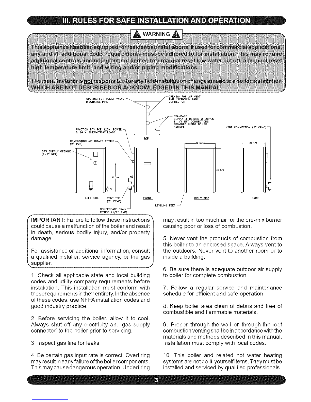
OPENING FOR AIR VENT
OPENING FOR RELIEF VALVE AND EXPANSION TANK
DISCHARGE PIPE CONNECTION
_t _ STANDARD
SUPPLY & RETURN OPENINGS
1 1/4 NPT CONNECTIONS
t ,+,+,,+,o,oo,+,c++.
JUNCTION BOX FOR 120V+ POWER
& 2,€ V. THERktOSTAT LEADS
_ _ TOP
COMBUSTION AIR INTAKE FITTING
(2" PVC)
GAS SUPPLY _ X_ _ '/+
OPENING _ \
(1/2" NPT)
r_l
FITTING (1/2" PVC)
LEVELING FEET
IMPORTANT: Failure to follow these instructions
could cause a malfunction of the boiler and result
in death, serious bodily injury, and/or property
damage.
For assistance or additional information, consult
a qualified installer, service agency, or the gas
VENT CONNECTION (2" CPVC)--
may result in too much air for the pre-mix burner
causing poor or loss of combustion.
5. Never vent the products of combustion from
this boiler to an enclosed space, Always vent to
the outdoors, Never vent to another room or to
inside a building,
1. Check all applicable state and local building
codes and utility company requirements before
installation. This installation must conform with
these requirements in their entirety. In the absence
of these codes, use NFPA installation codes and
good industry practice.
2. Before servicing the boiler, allow it to cool.
Always shut off any electricity and gas supply
connected to the boiler prior to servicing.
3. Inspect gas line for leaks.
6. Be sure there is adequate outdoor air supply
to boiler for complete combustion.
7. Follow a regular service and maintenance
schedule for efficient and safe operation.
8. Keep boiler area clean of debris and free of
combustible and flammable materials.
9. Proper through-the-watt or through-the-roof
combustion venting shall be in accordance with the
materials and methods described in this manual.
Installation must comply with local codes.
4. Be certain gas input rate is correct. Overfiring
may result in early failure of the boiter components.
This may cause dangerous operation. Underfiring
10. This boiler and related hot water heating
systems are not do-it-yourself items. They must be
installed and serviced by qualified professionals.
Page 4
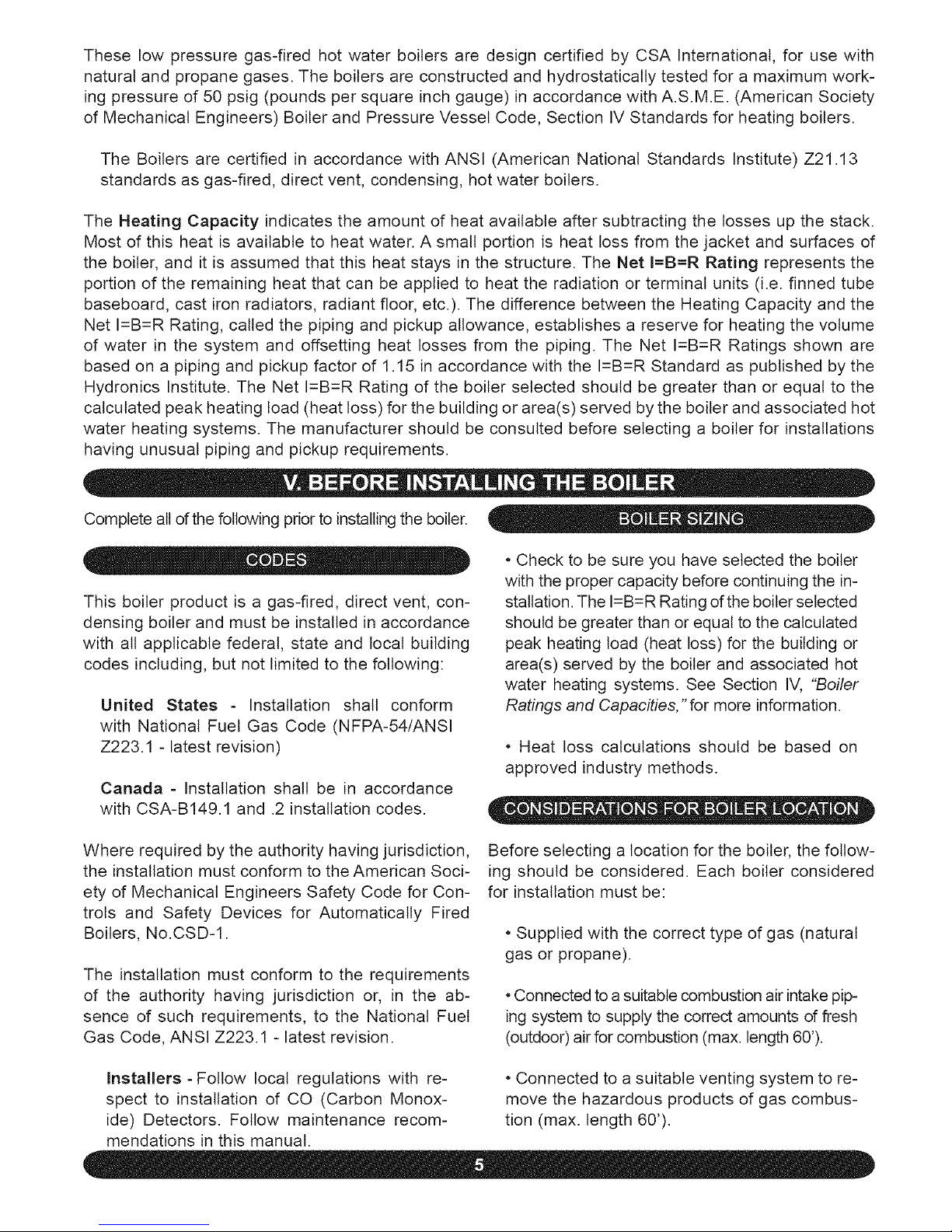
125 125 112.5
150 150 135
175 175 157.5
200 200 180
(1)1MBH=1,000 Btuh(British ThermalUnits PerHour)
98
117
137
157
284
284
284
284
90
90
90
90
2" CPVC & 3" PVC
2" CPVC & 3" PVC
2" CPVC & 3" PVC
2" CPVC & 3" PVC
(2)AFUE (Annual Fuel Utilization Efficiency) and Heating Capacity is based on Department of Energy test procedure.
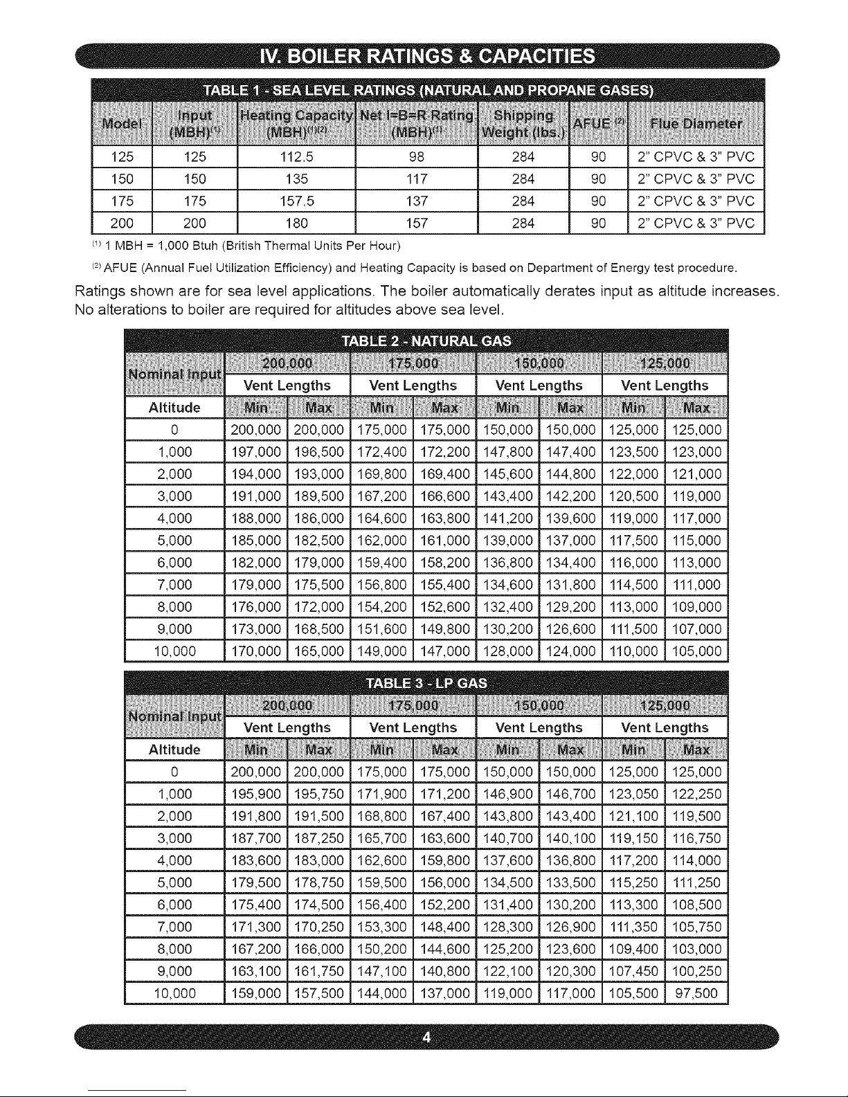
Ratings shown are for sea level applications. The boiler automatically derates input as altitude increases.
No alterations to boiler are required for altitudes above sea level.
Vent Lengths Vent Lengths Vent Lengths Vent Lengths
Altitude
0 200,000 200,000 175,000 175,000 150,000 150,000 125,000 125,000
1,000 197,000 196,500 172,400 172,200 147,800 147,400 123,500 123,000
2,000 194,000 193,000 169,800 169,400 145,600 144,800 122,000 121,000
3,000 191,000 189,500 167,200 166,600 143,400 142,200 120,500 119,000
4,000 188,000 186,000 164,600 163,800 141,200 139,600 119,000 117,000
5,000 185,000 182,500 162,000 161,000 139,000 137,000 117,500 115,000
6,000 182,000 179,000 159,400 158,200 136,800 134,400 116,000 113,000
7,000 179,000 175,500 156,800 155,400 134,600 131,800 114,500 111,000
8,000 176,000 172,000 154,200 152,600 132,400 129,200 113,000 109,000
9,000 173,000 168,500 151,600 149,800 130,200 126,600 111,500 107,000
10,000 170,000 165,000 149,000 147,000 128,000 124,000 110,000 105,000
Vent Lengths VentLengths Vent Lengths VentLengths
Altitude
0 200,000 200,000 175,000 175,000 150,000 150,000 125,000 125,000
1,000 195,900 195,750 171,900 171,200 146,900 146,700 123,050 122,250
2,000 191,800 191,500 168,800 167,400 143,800 143,400 121,100 119,500
3,000 187,700 187,250 165,700 163,600 140,700 140,100 119,150 116,750
4,000 183,600 183,000 162,600 159,800 137,600 136,800 117,200 114,000
5,000 179,500 178,750 159,500 156,000 134,500 133,500 115,250 111,250
6,000 175,400 174,500 156,400 152,200 131,400 130,200 113,300 108,500
7,000 171,300 170,250 153,300 148,400 128,300 126,900 111,350 105,750
8,000 167,200 166,000 150,200 144,600 125,200 123,600 109,400 103,000
9,000 163,100 161,750 147,100 140,800 122,100 120,300 107,450 100,250
10,000 159,000 157,500 144,000 137,000 119,000 117,000 105,500 97,500
Page 5
These low pressure gas-fired hot water boilers are design certified by CSA International, for use with
natural and propane gases. The boilers are constructed and hydrostatically tested for a maximum work-
ing pressure of 50 psig (pounds per square inch gauge) in accordance with A.S.M.E. (American Society
of Mechanical Engineers) Boiler and Pressure Vessel Code, Section IV Standards for heating boilers.
The Boilers are certified in accordance with ANSI (American National Standards Institute) Z21.13
standards as gas-fired, direct vent, condensing, hot water boilers.
The Heating Capacity indicates the amount of heat available after subtracting the losses up the stack.
Most of this heat is available to heat water. A small portion is heat loss from the jacket and surfaces of
the boiler, and it is assumed that this heat stays in the structure. The Net I=B=R Rating represents the
portion of the remaining heat that can be applied to heat the radiation or terminal units (i.e. finned tube
baseboard, cast iron radiators, radiant floor, etc.). The difference between the Heating Capacity and the
Net I=B=R Rating, called the piping and pickup allowance, establishes a reserve for heating the volume
of water in the system and offsetting heat losses from the piping. The Net I=B=R Ratings shown are
based on a piping and pickup factor of 1.15 in accordance with the I=B=R Standard as published by the
Hydronics Institute. The Net I=B=R Rating of the boiler selected should be greater than or equal to the
calculated peak heating load (heat loss) for the building or area(s) served by the boiler and associated hot
water heating systems. The manufacturer should be consulted before selecting a boiler for installations
having unusual piping and pickup requirements.
Complete all of the following prior to installing the boiler.
Oil
This boiler product is a gas-fired, direct vent, con-
densing boiler and must be installed in accordance
with all applicable federal, state and local building
codes including, but not limited to the following:
United States - Installation shall conform
with National Fuel Gas Code (NFPA-54/ANSI
Z223.1 - latest revision)
Canada - Installation shall be in accordance
with CSA-B149.1 and .2 installation codes.
• Check to be sure you have selected the boiler
with the proper capacity before continuing the in-
stallation. The I=B=R Rating of the boiler selected
should be greater than or equal to the calculated
peak heating load (heat loss) for the building or
area(s) served by the boiler and associated hot
water heating systems. See Section IV, "Boiler
Ratings and Capacities, " for more information.
• Heat loss calculations should be based on
approved industry methods.
Where required by the authority having jurisdiction,
the installation must conform to the American Soci-
ety of Mechanical Engineers Safety Code for Con-
trols and Safety Devices for Automatically Fired
Boilers, No.CSD-1.
The installation must conform to the requirements
of the authority having jurisdiction or, in the ab-
sence of such requirements, to the National Fuel
Gas Code, ANSI Z223.1 -latest revision.
Before selecting a location for the boiler, the follow-
ing should be considered. Each boiler considered
for installation must be:
• Supplied with the correct type of gas (natural
gas or propane).
•Connected to asuitable combustion air intake pip-
ing system to supply the correct amounts of fresh
(outdoor) air for combustion (max. length 60').
Installers - Follow local regulations with re- • Connected to a suitable venting system to re-
spect to installation of CO (Carbon Monox- move the hazardous products of gas combus-
ide) Detectors, Follow maintenance recom- tion (max, length 60'),
mendations in this manual,
Page 6
• Connectedto a suitablehot water heating
system.
• Supplied with a suitable electrical supply for
all boiler motors and controls.
• Connected to a properly located thermostat
or operating control. (not included with boiler)
• Placed on level surface (must NOT be in-
stalled on carpeting)
• Condensate drain line must be pitched down
to floor drain or external condensate pump with
reservoir at ¼"per foot (wood frame or blocks
may be used to raise boiler).
1. Select a location which is level, central to the
piping systems served and as close to the vent
and air intake terminals as possible.
2. Accessibility clearances, if more stringent (i.e.
larger clearances) than required fire protection
clearances, must be used for the boiler installa-
tion. Accessibility clearances may be achieved
with the use of removable walls or partitions.
3. The boiler is approved for installation in clos-
ets and on combustible floors. This boiler shall
NOT be installed on carpeting.
the front where passage is required for cleaning or
servicing, inspection or replacement d any parts
that normally may require such attention. Allow at
least 24" at the front and left side and 8" at the top
for servicing. No combustible clearances are re-
quired to venting or combustion air intake piping.
5. Equipment shall be installed in a location
which facilitates the operation of venting and
combustion air intake piping systems as de-
scribed in this manual.
6. Advise owner of boiler to keep venting and
combustion air intake passages free of obstruc-
tions, Both the venting and combustion air intake
piping systems connected to the outdoors must
permit flow through the piping systems without
restrictions for the boiler to operate,
7. The boiler shall be installed such that the
automatic gas ignition system components are
protected from water (dripping, spraying, rain,
etc.) during operation and service (circulator re-
placement, control replacement, etc.).
8. The boiler must be located where ambient
temperatures (minimum possible room temper-
atures where boiler is installed assuming boiler
is not in operation and therefore contributes no
heat to the space) are always at or above 32°F
to prevent freezing of liquid condensate.
Top 1" 8"
Left Side 8" 24"
Right Side 1"
Base 1"
Front 0" 24"
Back 1"
Intake/Vent
0"
Piping
Near Boiler Hot
1"
Water Piping
Aft distances measured from the cabinet of the boiler.
4. The clearances shown in Table 4 indicate re-
quired clearances per CSA listing. A min. 1" clear-
ance must be maintained between combustible
construction and each of the right, top and back
surfaces of the boiler. A min. 8" clearance is re-
quired on the left side, to allow room for the inlet
air pipe. An 18" clearance must be maintained at
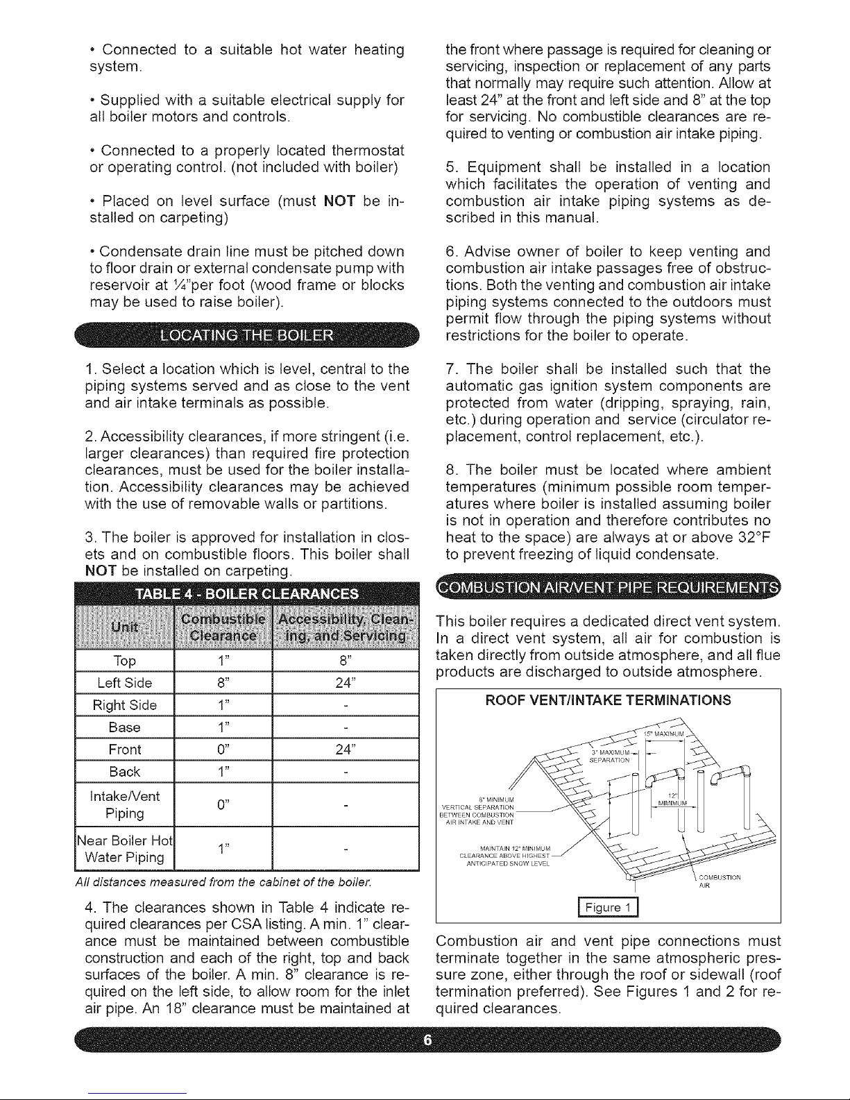
This boiler requires a dedicated direct vent system.
In a direct vent system, all air for combustion is
taken directly from outside atmosphere, and all flue
)roducts are discharged to outside atmosphere.
ROOF VENTIINTAKE TERMINATIONS
I Figure 1]
Combustion air and vent pipe connections must
terminate together in the same atmospheric pres-
sure zone, either through the roof or sidewall (roof
termination preferred). See Figures 1 and 2 for re-
quired clearances.
Page 7
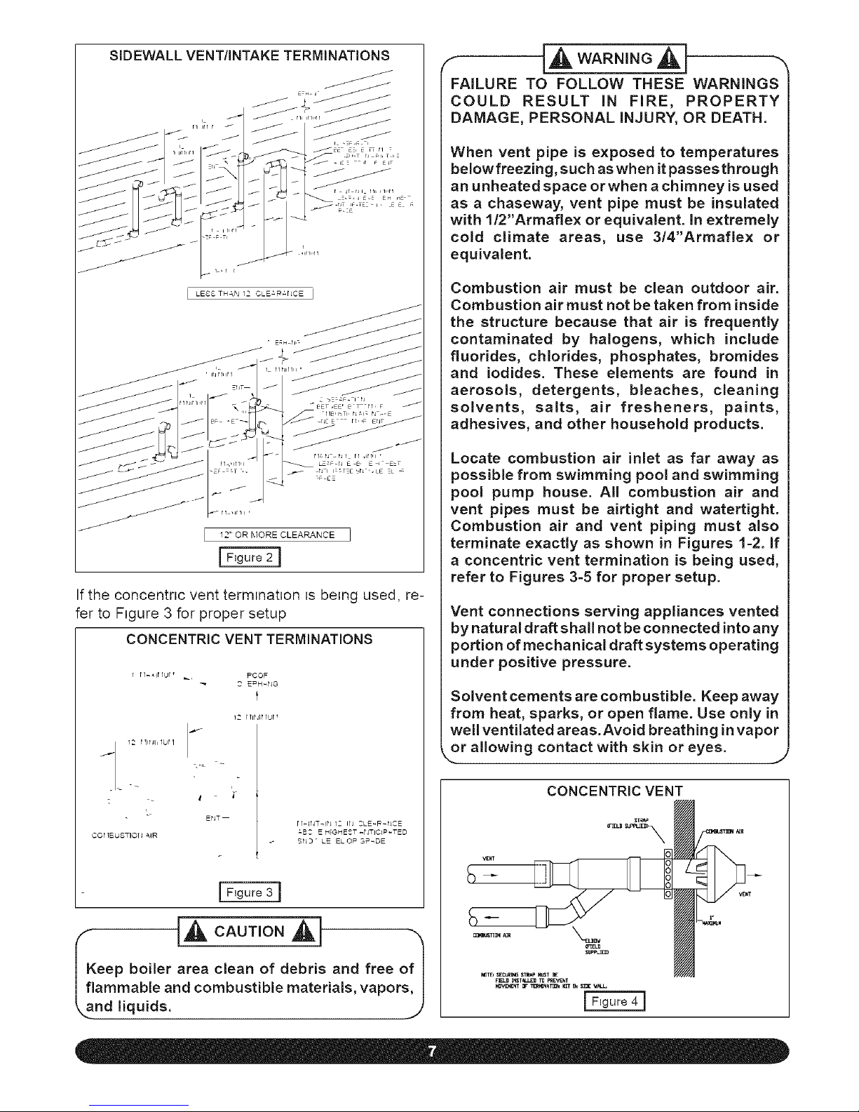
SIDEWALL VENTIINTAKE TERMINATIONS
I LESS THAN 12 CLE;,R;,riCE J
12" OR MORE CLEARANCE
If the concentnc vent termination is being used, re-
fer to Figure 3 for proper setup
CONCENTRIC VENT TERMINATIONS
12_ P IlNll 1UP 1
I
COt 1EUSTIOH AIR
_1 PCOF
3 E_=H-IIG
t
12 I11PJRIIJ[ _
J
ENT
r1-ff4T_in IC irl CLE-_-NCE
:BC E H;GHEST .NTIC_P-TED
SI_ ' LE ELOF = SP-DE
eep boiler area clean of debris and free of I
ammable and combustible materials, vapors, I
nd liquids, i,)
FAILURE TO FOLLOW THESE WARNINGS
COULD RESULT IN FIRE, PROPERTY
DAMAGE, PERSONAL INJURY, OR DEATH.
When vent pipe is exposed to temperatures
below freezing, such as when it passes through
an unheated space or when a chimney is used
as a chaseway, vent pipe must be insulated
with l/2"Armaflex or equivalent. In extremely
cold climate areas, use 3/4"Armaflex or
equivalent.
Combustion air must be clean outdoor air.
Combustion air must not be taken from inside
the structure because that air is frequently
contaminated by halogens, which include
fluorides, chlorides, phosphates, bromides
and iodides. These elements are found in
aerosols, detergents, bleaches, cleaning
solvents, salts, air fresheners, paints,
adhesives, and other household products.
Locate combustion air inlet as far away as
possible from swimming pool and swimming
pool pump house. All combustion air and
vent pipes must be airtight and watertight.
Combustion air and vent piping must also
terminate exactly as shown in Figures 1-2. If
a concentric vent termination is being used,
refer to Figures 3-5 for proper setup.
Vent connections serving appliances vented
by natural draft shall not be connected into any
portion of mechanical draft systems operating
under positive pressure.
Solvent cements are combustible. Keep away
from heat, sparks, or open flame. Use only in
well ventilated areas. Avoid breathing in vapor
k.or allowing contact with skin or eyes. J
CONCENTRIC VENT
Page 8
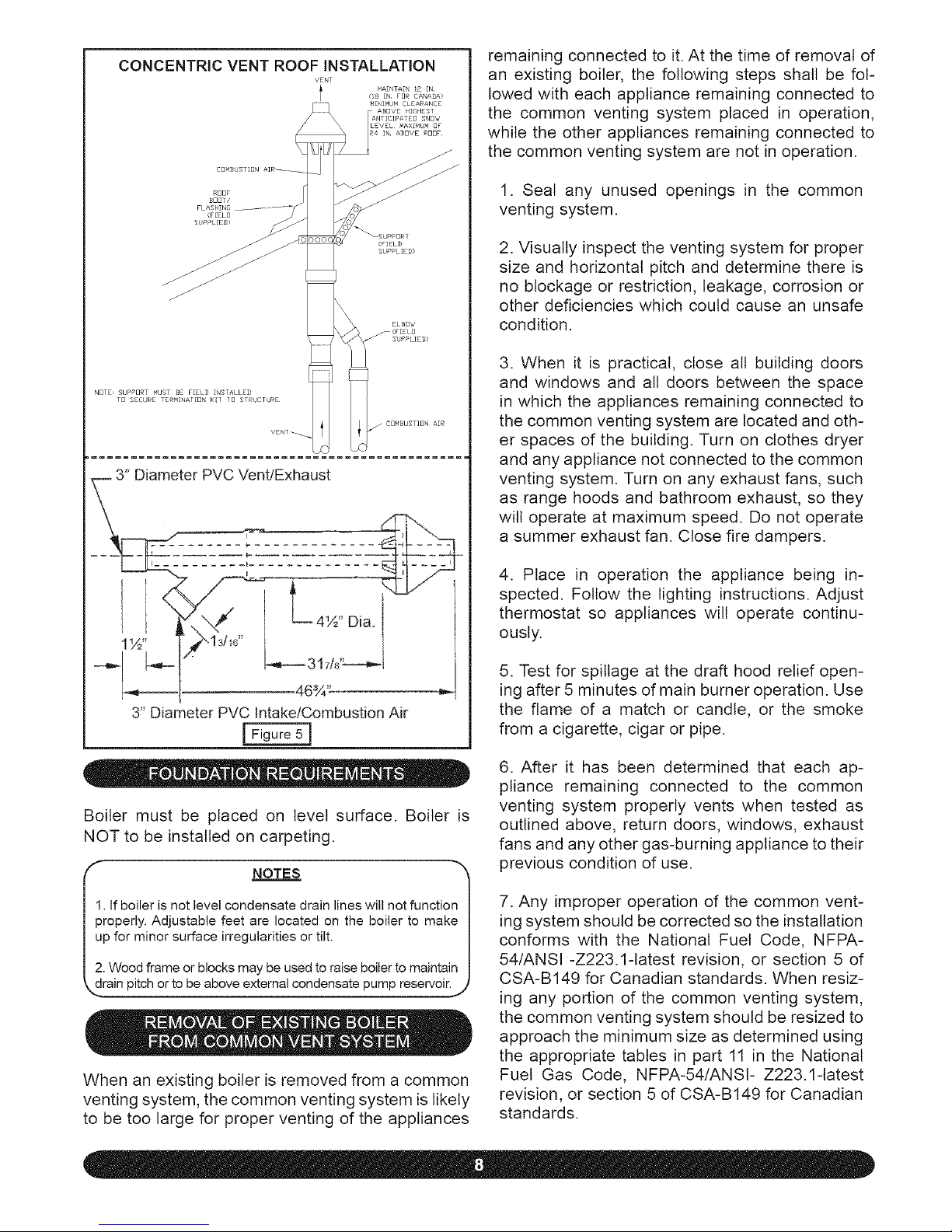
CONCENTRICVENTROOFINSTALLATION
VENT
I MAINTAIN 12 IN
(i8 IN FD_ CANADA>
MINI_UN CLEARANCE
SNO_
MAXINUM OF
IN A_DVE NOOF
NOTE, SbPPORT WUST BE FIELD INSTALLED
TO SECC_RE TERMINAT[0N K!I /O STR/JCTURE
3" Diameter PVC Vent/Exhaust
1W' ,¢"_1d1_'
46% _
3" Diameter PVC Intake/Combustion Air
[ Figure 5 I
Boiler must be placed on level surface. Boiler is
NOT to be installed on carpeting.
NOTES
1. If boiler is not level condensate drain lines will not function
properly. Adjustable feet are located on the boiler to make
up for minor surface irregularities or tilt.
2. Wood frame or blocks may be used to raise boiler to maintain
Wa!np!!chor!obeabovee erna!condensa!epump
When an existing boiler is removed from a common
venting system, the common venting system is likely
to be too large for proper venting of the appliances
remaining connected to it. At the time of removal of
an existing boiler, the following steps shall be fol-
lowed with each appliance remaining connected to
the common venting system placed in operation,
while the other appliances remaining connected to
the common venting system are not in operation.
1. Seal any unused openings in the common
venting system.
2. Visually inspect the venting system for proper
size and horizontal pitch and determine there is
no blockage or restriction, leakage, corrosion or
other deficiencies which could cause an unsafe
condition.
3. When it is practical, close all building doors
and windows and all doors between the space
in which the appliances remaining connected to
the common venting system are located and oth-
er spaces of the building. Turn on clothes dryer
and any appliance not connected to the common
venting system. Turn on any exhaust fans, such
as range hoods and bathroom exhaust, so they
will operate at maximum speed. Do not operate
a summer exhaust fan. Close fire dampers.
4. Place in operation the appliance being in-
spected. Follow the lighting instructions. Adjust
thermostat so appliances will operate continu-
ously.
5. Test for spillage at the draft hood relief open-
ing after 5 minutes of main burner operation. Use
the flame of a match or candle, or the smoke
from a cigarette, cigar or pipe.
6. After it has been determined that each ap-
pliance remaining connected to the common
venting system properly vents when tested as
outlined above, return doors, windows, exhaust
fans and any other gas-burning appliance to their
previous condition of use.
7. Any improper operation of the common vent-
ing system should be corrected so the installation
conforms with the National Fuel Code, NFPA-
54/ANSI -Z223.1-1atest revision, or section 5 of
CSA-B149 for Canadian standards. When resiz-
ing any portion of the common venting system,
the common venting system should be resized to
approach the minimum size as determined using
the appropriate tables in part 11 in the National
Fuel Gas Code, NFPA-54/ANSI- Z223.1-tatest
revision, or section 5 of CSA-B149 for Canadian
standards.
Page 9
The boiler should be placed to provide the most
direct connections to the combustion air, vent and
system piping as possible.
Place crated boiler as close to selected location
as possible and uncrate boiler. The uncrated boiler
may be moved into position with an appliance dol-
ly or 2-wheel hand truck. The dolly or hand truck
should be inserted under the right hand side of
the boiler. It is possible to slide the boiler for a short
distance on a smooth floor or surface.
NqNOTE: Refer to "Locating The Boiler" in Section V for re-_
uired clearances for servicing and maintenance.
J
r c.o,,o, .,
Copper supply and return piping must NOT be in-
stalled directly into aluminum boiler section castings
due to galvanic corrosion between dissimilar met-
als. Iron or steel bushings or pipe nipples should
be used between copper system piping and boiler
to make final connection to boiler. Also, the use d
dielectric unions is acceptable. The packaged boiler
is furnished with iron piping in the front boiler sec-
k_ion for the supply and return connections.
J
When the installation of the boiler is for a new heat-
ing system, first install all of the radiation units (pan-
els, radiators, baseboard, or tubing) and the supply
and return mains. After all heating system piping and
components have been installed, make final con-
nection of the system piping to the boiler.
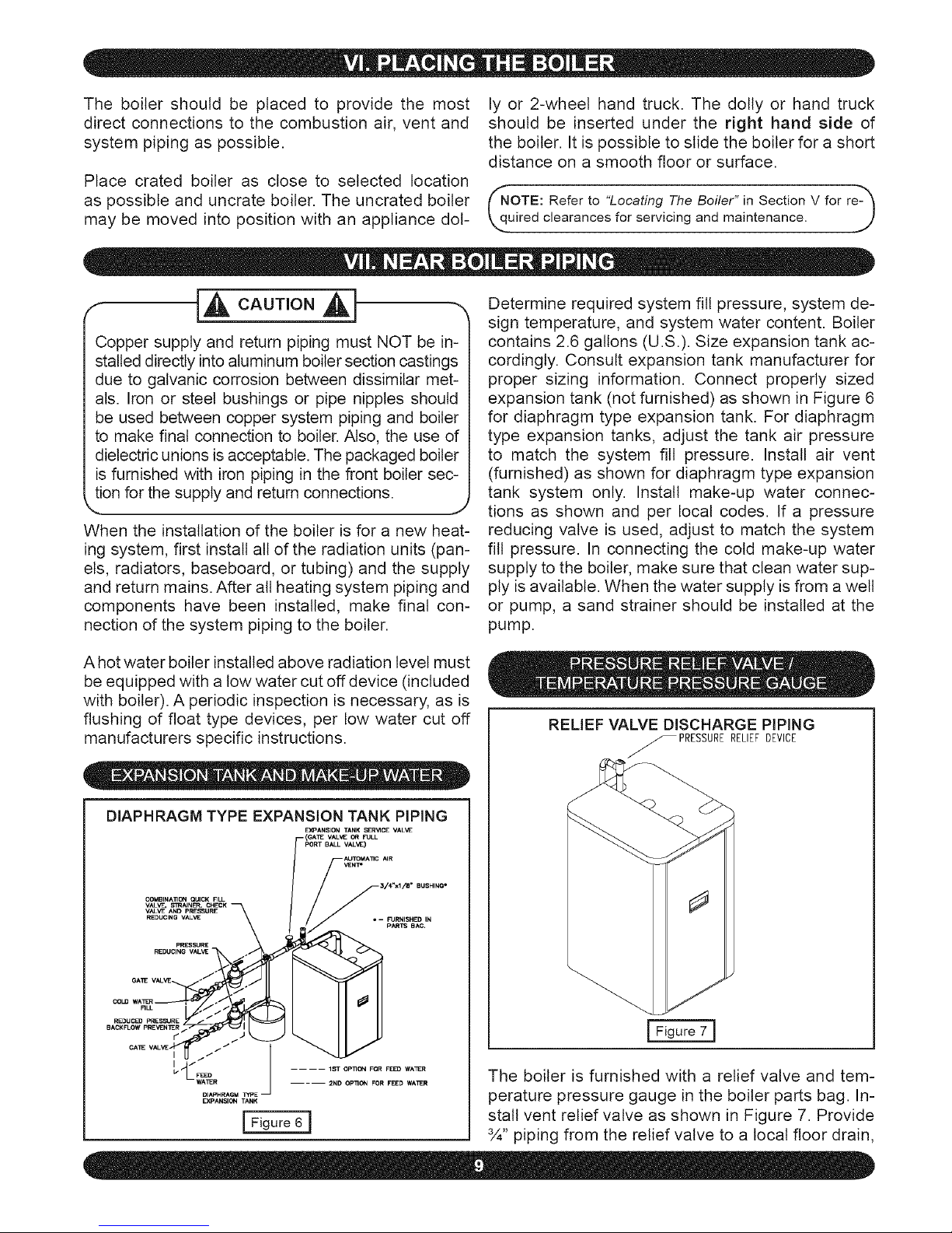
Determine required system fill pressure, system de-
sign temperature, and system water content. Boiler
contains 2.6 gallons (U.S.). Size expansion tank ac-
cordingly. Consult expansion tank manufacturer for
proper sizing information. Connect properly sized
expansion tank (not furnished) as shown in Figure 6
for diaphragm type expansion tank. For diaphragm
type expansion tanks, adjust the tank air pressure
to match the system fill pressure. Install air vent
(furnished) as shown for diaphragm type expansion
tank system only. Install make-up water connec-
tions as shown and per local codes. If a pressure
reducing valve is used, adjust to match the system
fill pressure. In connecting the cold make-up water
supply to the boiler, make sure that clean water sup-
ply is available. When the water supply is from a well
or pump, a sand strainer should be installed at the
pump.
A hot water boiler installed above radiation level must
be equipped with a low water cut off device (included
with boiler). A periodic inspection is necessary, as is
flushing of float type devices, per low water cut off
manufacturers specific instructions.
DIAPHRAGM TYPE EXPANSION TANK PIPING
E)G_ANSION TANK SER_ICE VALVE
{OA_ VALVE Of_ FULL
PORT BALL VAL'_)
AUTOMATIC AIR
VENT*
.............\ •
REDUCING VALVE *- FURNISHED IN
pARTS BAG.
REDUCINGVALVE
I _/ .... 1ST Op_cN FOR FEED WA3ER
WA_R 2ND Opllo_ FOR FEED WAER
DIAPHRAGM TfPE-
EXPANSION TANK
RELIEF VALVE DISCHARGE PiPiNG
PRESSURERELIEFDEVICE
Figure 7 ]
The boiler is furnished with a relief valve and tem-
perature pressure gauge in the boiler parts bag. In-
stall vent relief valve as shown in Figure 7. Provide
¾" piping from the relief valve to a local floor drain,
Page 10
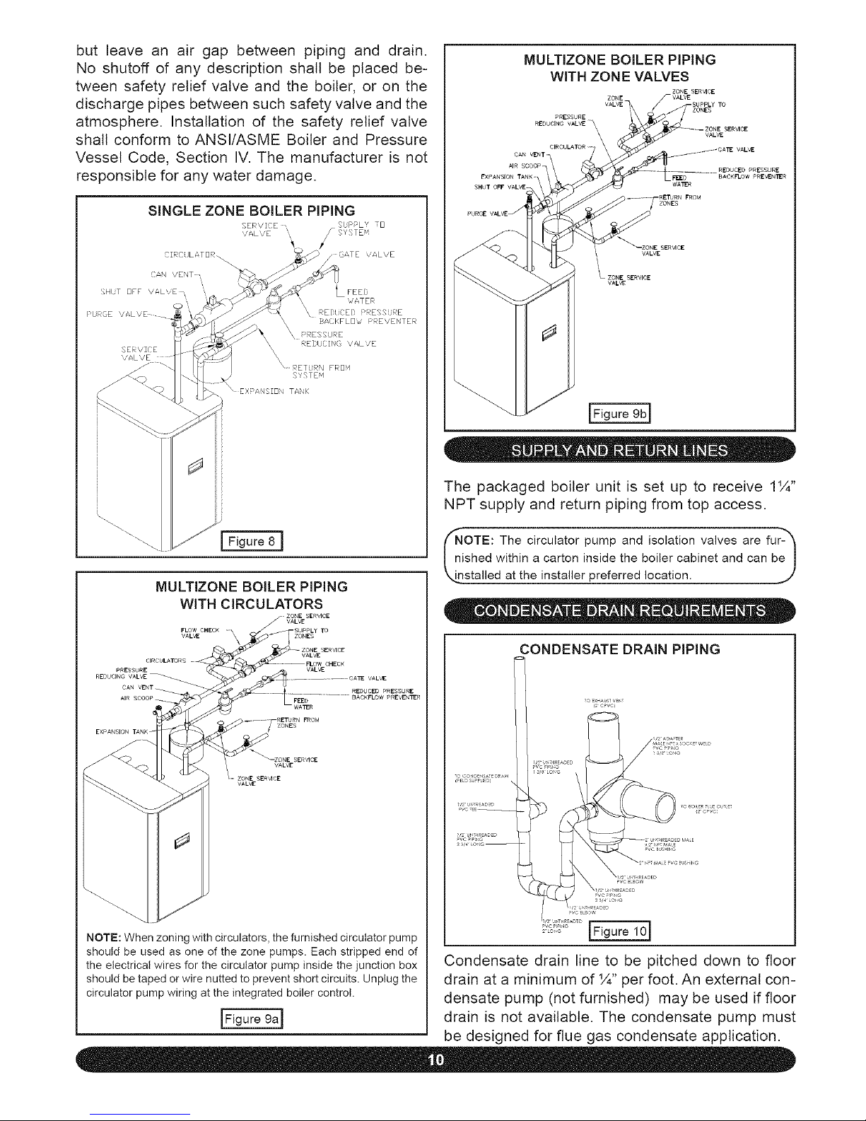
but leave an air gap betweenpiping and drain.
No shutoff of any descriptionshall be placedbe-
tweensafetyreliefvalveandthe boiler,or on the
dischargepipesbetweensuchsafetyvalveandthe
atmosphere.Installationof the safety reliefvalve
shallconformto ANSI/ASMEBoilerand Pressure
VesselCode,SectionIV.The manufactureris not
responsibleforanywaterdamage.
SINGLEZONEBOILERPiPiNG
SERVI E S[ PPLY [3
VALVE
SE \/Z(?E
'ALVE
MULTIZONE BOILER PiPiNG
WiTH CIRCULATORS
_-ZONE SERVICE
j" VALVE
FLOW CHECK TO
VALVE ZONES
CIRCULATORS
PRESSURE
REDUClNO VALVE_
VALVE
VAL_
NOTE: When zoning with circulators, the furnished circulator pump
should be used as one of the zone pumps. Each stripped end of
the electrical wires for the circulator pump inside the junction box
should be taped or wire nutted to prevent short circuits. Unplug the
circulator pump wiring at the integrated boiler control.
MULTIZONE BOILER PIPING
WiTH ZONE VALVES
ZONE SER_CE
ZONE F VALVE
VALVE-
ZONES
PRESSURE
REDUCING VALVE_ VALVE
CAN VENT /
AIR
WATER
ZONES
PRESSURE
BACKFLOW PREVEN_R
VALVE
_ZONE SERVICE
VALVE
IFlguregb]
The packaged boiler unit is set up to receive 1¼"
NPT supply and return piping from top access.
COTE: The circulator and isolation valves fur- _
pump
are
ished within a carton inside the boiler cabinet and can be]
_installed at the installer preferred location, j'
CONDENSATE DRAIN PIPING
Condensate drain line to be pitched down to floor
drain at a minimum of ¼" per foot. An external con-
densate pump (not furnished) may be used if floor
drain is not available. The condensate pump must
be designed for flue gas condensate application.
Page 11
NOTES
1. Condensate trap is to be built in the field per Figure 10
2. Wood frame or blocks may be used to raise the boiler
to maintain drain pitch or to be above external condensate
pump reservoir.
3. There is a 115 volt AC receptacle provided on the service
switch junction box which is located at the boiler right side, to
provide power for an external condensate pump (if needed).
\ J
The condensate trap is to be field installed as previ-
ously shown in Figure 10. Provided are ½" PVC fit-
tings for the condensate drain trap (assembled in the
field). The condensate drain is to be pitched down to
the floor drain at a minimum of ¼" per foot.
The ½" diameter schedule 40 PVC condensate
drain piping and pipe fittings must conform to ANSI
standards and ASTM D1785 or D2846. Schedule
40 PVC cement and primer must conform to ASTM
D2564 or F493. In Canada, use CSA or ULC certi-
fied schedule 40 PVC drain pipe and cement.
A condensate pump with a reservoir (not furnished)
may be used to remove condensate to a drain line
(sanitary line) above boiler if a floor drain is not
available or is inaccessible.
ON INITIAL START UP THE CONDENSATE TRAP
MUST BE MANUALLY FILLED WITH WATER.
The following are the steps required to initially fill
the condensate trap for start up, these steps are
only required at the initial start up or if maintenance
requires draining of the condensate trap:
1. Pour about 1 cup of cold tap water into the
condensate trap vent.
2. Excess water should go through the conden-
sate drain line. Verify proper operation of the drain
line (and external condensate pump if used).
The boiler, when used in connection with a refrig-
eration system, must be installed so the chiller me-
dium is piped in parallel with the boiler with appro-
priate valves to prevent the chilled medium from
entering the boiler.
The boiler piping system of a hot water boiler con-
nected to heating coils located in air handling units
where they may be exposed to refrigerated air cir-
culation must be equipped with flow control valves
or other automatic means to prevent gravity circu-
lation of the boiler water during the cooling cycle.
I_IPORTANT: To prevent damage to the gas"_
urner and ensure proper operation of the unit, I
stalter must clean and remove all shavings from I
e interior of all PVC pipe used on the air intake.>]
For boilers connected to gas vents or chimneys, vent
installations shall be in accordance with part 7, Venting
of Equipment, d the National Fuel Gas Code, ANSI
Z223.1-1atest revision, CSA-B149.1 and B149.2, and
applicable provisions d the local building codes.
Provisions for combustion and ventilation air must
be in accordance with section 5.3, Air For Com-
bustion and Ventilation, of the National Fuel Gas
Code, ANSI Z223.1-1atest revision, CSA-B149.1
and B149.2, or applicable provisions of the local
building code.
outdoors through the combustion air intake pipe.
All flue products are discharged to the outdoors
through the vent pipe.
1. See Figures 1-2 in Section V, "Combustion Air
and Vent Pipe Requirements," for standard two-
pipe roof and sidewall terminations and Figures
3-5 (same section) for concentric vent termina-
tions (roof termination is preferred). Combus-
tion air and vent pipes must terminate together
in same atmospheric pressure zone as shown.
Construction through which vent and air intake
pipes may be installed is a minimum ¼" and max-
imum 24" thickness.
2. Combustion air and vent pipe fittings must con-
form to one of the following American National
Standards Institute (ANSI) and American Society
for Testing and Materials (ASTM) standards:
• D1784 (schedule-40 CPVC)
These boilers require a dedicated direct vent sys-
tem. All air for combustion is taken directly from
• D1785 (schedule-40 PVC)
Page 12
• D2665 (PVC-DWV) Reduce the maximum vent length 5 feet per
each additional elbow.
• D2241 (SDR-21 and SDR-26 PVC)
• D2661 (ABS-DWV)
• F628 (schedule-40 ABS).
Pipe cement and primer must conform to ASTM
standards D2564 (PVC) or D2235 (ABS).
In Canada construct all combustion air and vent
pipes for this unit of CSA or U LC certified sched-
ule-40 CPVC, schedule-40 PVC, PVC-DWV or
ABS-DWV pipe and pipe cement. SDR pipe is
NOT approved in Canada.
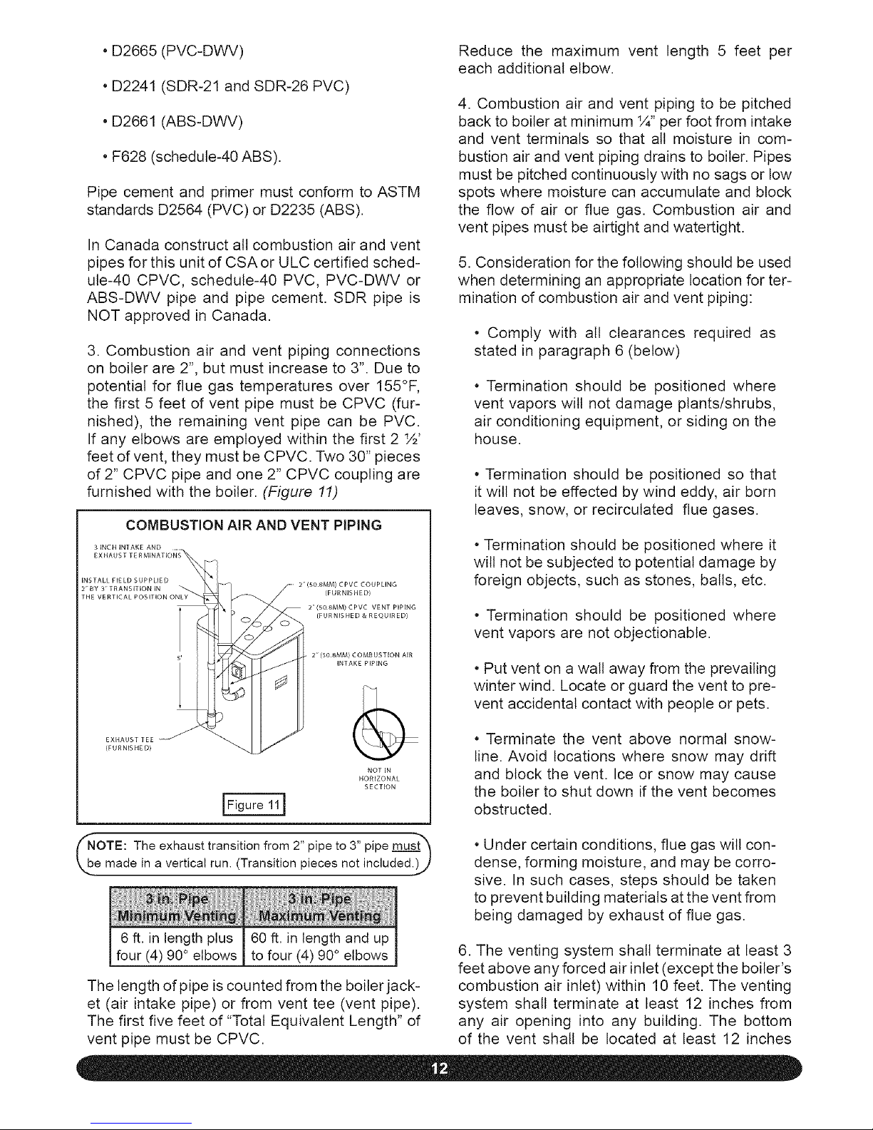
3. Combustion air and vent piping connections
on boiler are 2", but must increase to 3". Due to
potential for flue gas temperatures over 155°F,
the first 5 feet of vent pipe must be CPVC (fur-
nished), the remaining vent pipe can be PVC.
If any elbows are employed within the first 2 ½'
feet of vent, they must be CPVC. Two 30" pieces
of 2" CPVC pipe and one 2" CPVC coupling are
furnished with the boiler. (Figure 11)
COMBUSTION AIR AND VENT PIPING
2 (508MM) CPVC COUPLING
(FURNISHED)
2 (508MM) CPVC VENT PIPING
(FURNISHED & REQUIRED)
2 (50 8MM) COMBUSTION AIR
INTAKE PIPING
(FURNISHED)
NOT IN
HORIZONAL
SECTION
4. Combustion air and vent piping to be pitched
back to boiler at minimum ¼" per foot from intake
and vent terminals so that all moisture in com-
bustion air and vent piping drains to boiler. Pipes
must be pitched continuously with no sags or low
spots where moisture can accumulate and block
the flow of air or flue gas. Combustion air and
vent pipes must be airtight and watertight.
5. Consideration for the following should be used
when determining an appropriate location for ter-
mination of combustion air and vent piping:
• Comply with all clearances required as
stated in paragraph 6 (below)
• Termination should be positioned where
vent vapors wilt not damage plants/shrubs,
air conditioning equipment, or siding on the
house.
• Termination should be positioned so that
it will not be effected by wind eddy, air born
leaves, snow, or recircutated flue gases.
• Termination should be positioned where it
will not be subjected to potential damage by
foreign objects, such as stones, balls, etc.
• Termination should be positioned where
vent vapors are not objectionable.
• Put vent on a wall away from the prevailing
winter wind. Locate or guard the vent to pre-
vent accidental contact with people or pets.
• Terminate the vent above normal snow-
line. Avoid locations where snow may drift
and block the vent. Ice or snow may cause
the boiler to shut down if the vent becomes
obstructed.
NOTE: The exhaust transition from 2" pipe to 3" pipe must_
e made in a vertical run. (Transition pieces not included.)_
6 ft. in length plus 60 ft. in length and up
four (4) 90° elbows to four (4) 90° elbows
The length of pipe is counted from the boiler jack-
et (air intake pipe) or from vent tee (vent pipe).
The first five feet of "Total Equivalent Length" of
vent pipe must be CPVC.
• Under certain conditions, flue gas will con-
dense, forming moisture, and may be corro-
sive. In such cases, steps should be taken
to prevent building materials at the vent from
being damaged by exhaust of flue gas.
6. The venting system shall terminate at least 3
feet above any forced air inlet (except the boiler's
combustion air inlet) within 10 feet. The venting
system shall terminate at least 12 inches from
any air opening into any building. The bottom
of the vent shall be located at least 12 inches
Page 13
abovegrade.Terminationof the vent shall be
not lessthan 7 feet abovean adjacentpublic
walkway.Theventterminalshallnotbeinstalled
closerthan3 feetfromtheinsidecornerof an L
shapedstructure.Terminationoftheventshould
be keptat least 3 feet awayfrom vegetation.
The venting systemshall terminateat least4
feet horizontallyfrom, andinno caseaboveor
below electric meters,gas meters,regulators,
andreliefequipment.
Ifmultipleterminationsareused,theremustbe
a minimumof 12 inchesbetweenthe exhaust
of oneterminationandthe air intakeof the next
termination.SeeFigures1-3inSectionE5for il-
lustrations.
NOTE: All field installed vent pipe must be 3". b
6. Check dry fit of pipe and mark insertion depth
on pipe.
NOTE: It is recommended that all pipes be cut, prepared, and-"_
J
re-assembled before permanently cementing any joint.
7. After pipes have been cut and pre-assem-
bled, apply cement primer to pipe fitting socket
and end of pipe to insertion mark. Quickly apply
approved cement to end of pipe and fitting sock-
et (over primer). Apply cement in light, uniform
coat on the inside of socket to prevent buildup of
excess cement. Apply second coat.
8. While cement is still wet, insert pipe into sock-
et with a ¼ turn twist. Be sure pipe is fully in-
serted into fitting socket.
1. Attach combustion air intake piping to sup-
plied Fernco 2" coupling on CVI gas valve. At-
tach vent piping to furnished 2" CPVC vent tee
on draft inducer outlet.
NOTE:All pipe joints are to be water tight.
2. Working from the boiler to the outside, cut
pipe to required length(s).
3. Deburr inside and outside of pipe. Remove all
chips and shavings.
4. Chamfer outside edge of pipe for better distri-
bution of primer and cement.
5. Clean and dry all surfaces to be joined.
9. Wipe excess cement from joint. A continuous
bead of cement wilt be visible around perimeter
of a properly made joint.
10. Handle pipe joint carefully until cement sets.
11. Support combustion air and vent piping a mini-
mum of every 5 feet using pre-formed metal hang-
ing straps. Do not rigidly support pipes. Allow for
movement due to expansion and contraction.
NOTE: Rigid supports will cause excess noise in vent piping)
12. Slope combustion air and vent pipes toward
boiler a minimum of ¼" per linear foot with no
sags between hangers.
13. Use appropriate methods to seat open-
ings where vent and combustion air pipes pass
through roof or side wall.
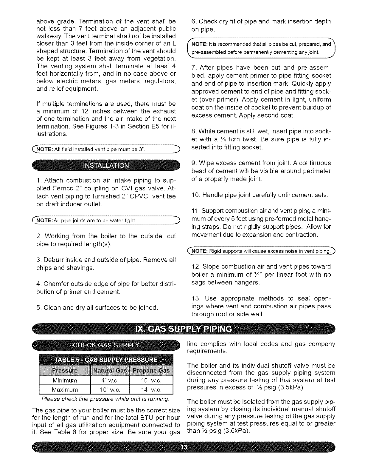
line complies with local codes and gas company
requirements.
Minimum 4" w.c. 10"w.c.
Maximum 10" w.c. 14"w.c.
Please check fine pressure while unit is running.
The gas pipe to your boiler must be the correct size
for the length of run and for the total BTU per hour
input of all gas utilization equipment connected to
it. See Table 6 for proper size. Be sure your gas
The boiler and its individual shutoff valve must be
disconnected from the gas supply piping system
during any pressure testing of that system at test
pressures in excess of ½ psig (3.5kPa).
The boiler must be isolated from the gas supply pip-
ing system by closing its individual manual shutoff
valve during any pressure testing of the gas supply
piping system at test pressures equal to or greater
than ½ psig (3.5kPa).
Page 14
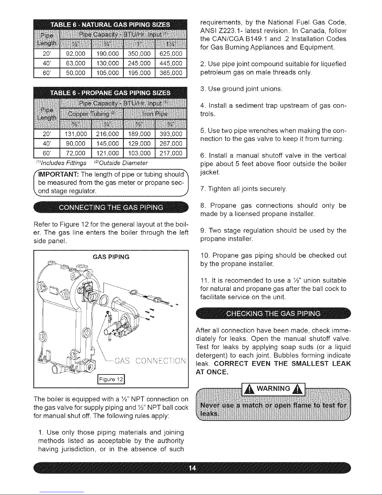
20' 92,000 190,000 350,000 625,000
40' 63,000 130,000 245,000 445,000
60' 50,000 105,000 195,000 365,000
requirements,by the NationalFuelGas Code,
ANSIZ223.1-latestrevision.In Canada,follow
theCAN/CGAB149.1and .2 InstallationCodes
for GasBurningAppliancesandEquipment.
2.Usepipejointcompoundsuitableforliquefied
petroleumgason malethreadsonly.
20' 131,000 216,000 189,000 393,000
40' 90,000 145,000 129,000 267,000
60' 72,000 121,000 103,000 217,000
_JlncludesFittings _80utside Diameter
_obMPORTANT: length pipe or tubing should_
The of
e measured from the gas meter or propane sec- I
nds!ageregu!a!or: J
Refer to Figure 12 for the general layout at the boil-
er. The gas line enters the boiler through the left
side panel.
GAS PIPING
CONNECTION
The boiler is equipped with a ½" NPT connection on
the gas valve for supply piping and ½" NPT ball cock
for manual shut off. The following rules apply:
3. Use ground joint unions.
4. Install a sediment trap upstream of gas con-
trols.
5. Use two pipe wrenches when making the con-
nection to the gas valve to keep it from turning.
6. Install a manual shutoff valve in the vertical
pipe about 5 feet above floor outside the boiler
jacket.
7. Tighten all joints securely.
8. Propane gas connections should only be
made by a licensed propane installer.
9. Two stage regulation should be used by the
propane installer.
10. Propane gas piping should be checked out
by the propane installer.
11. It is recomended to use a ½" union suitable
for natural and propane gas after the ball cock to
facilitate service on the unit.
After all connection have been made, check imme-
diately for leaks. Open the manual shutoff valve.
Test for leaks by applying soap suds (or a liquid
detergent) to each joint. Bubbles forming indicate
leak. CORRECT EVEN THE SMALLEST LEAK
AT ONCE.
1. Use only those piping materials and joining
methods listed as acceptable by the authority
having jurisdiction, or in the absence of such
Page 15
WARNING
All electrical work must conform to local codes as
welt as the National Electrical Code, ANSI/NFPA-
70, latest revision. In Canada, electrical wiring shall
comply with the Canadian Electrical Codes, CSA-
C22.1 and .2.
The boiler, when installed, must be electrically
grounded in accordance with the requirements of
the authority having jurisdiction or, in the absence
of such requirements, with the National Electrical
Code, ANSI/NFPA-70, latest revision. In Canada,
electrical wiring shall comply with the Canadian
Electrical Codes, CSA-C22.1 and .2.
Run a 14 gauge or heavier copper wire from the
boiler to a grounded connection in the service pan-
el or a properly driven and electrically grounded
ground rod.
Prior to making any line voltage connections, ser-
vice switch at boiler should be in the off position
and the power turned off at the fuse box.
Run a 120 volt circuit from a separate over current
protection device in the electrical service entrance
panel.
CNOTE: Use copper conductors only. ,,._)
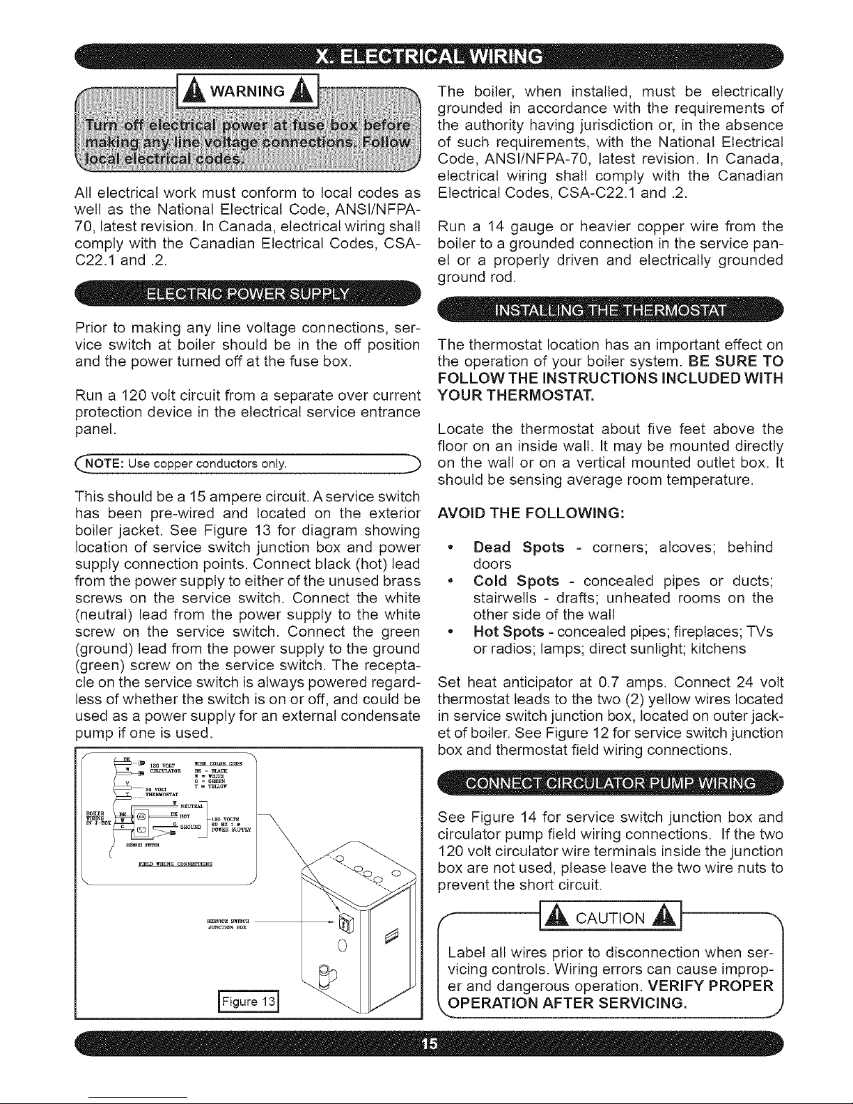
This should be a 15 ampere circuit. Aservice switch
has been pre-wired and located on the exterior
boiler jacket. See Figure 13 for diagram showing
location of service switch junction box and power
supply connection points. Connect black (hot) lead
from the power supply to either of the unused brass
screws on the service switch. Connect the white
(neutral) lead from the power supply to the white
screw on the service switch. Connect the green
(ground) lead from the power supply to the ground
(green) screw on the service switch. The recepta-
cle on the service switch is always powered regard-
less of whether the switch is on or off, and could be
used as a power supply for an external condensate
pump if one is used.
/f _K 1
_ _ 12o volt wi_ co_R CODE
_ CmCIII_TOR BK = 13Ia_
_ W = wIlrrE
y _ = GIVEN
_-- 24 VOLT Y = "l_l,LO_
G 60 IIZ i _
ZN_ BO: _ _ GROUl_ pOI_I_ SUPpLy
s_eE _
Figure 131
The thermostat location has an important effect on
the operation of your boiler system. BE SURE TO
FOLLOW THE INSTRUCTIONS INCLUDED WITH
YOUR THERMOSTAT.
Locate the thermostat about five feet above the
floor on an inside wall. It may be mounted directly
on the wall or on a vertical mounted outlet box. It
should be sensing average room temperature.
AVOID THE FOLLOWING:
. Dead Spots - corners; alcoves; behind
doors
. Cold Spots - concealed pipes or ducts;
stairwells - drafts; unheated rooms on the
other side of the watt
• Hot Spots - concealed pipes; fireplaces; TVs
or radios; lamps; direct sunlight; kitchens
Set heat anticipator at 0.7 amps. Connect 24 volt
thermostat leads to the two (2) yellow wires located
in service switch junction box, located on outer jack-
et of boiler. See Figure 12 for service switch junction
box and thermostat field wiring connections.
See Figure 14 for service switch junction box and
circulator pump field wiring connections. If the two
120 volt circulator wire terminals inside the junction
box are not used, please leave the two wire nuts to
prevent the short circuit.
Io
abet all wires prior to disconnection when set- I
icing controls. Wiring errors can cause improp- I
r and dangerous operation. VERIFY PROPER I
PERATION AFTER SERVICING. ,,j)
Page 16

SCHEMATICWIRINGCONNECTIONS
NOTE: If any of the original wire as supplied with this appliance must be replaced, it must be replaced with type 150°C Thermoplastic wire or its equivalent.
INTEGRATED BO_LER CONTROL
i
L "_ _]i SETSWI]CH(N C)AT SWITCH(NO)sETAT SECONDARY
i !"_T_I_!I C 05 W(. eL .....
Y
_] GN}T_R
P7
120VAC
I_AGNOSTC iNDICATORLIGI4TS
@ POWER
PURGE
IGNITOR
(_ VALW
(NOTE: USE COPPER CON[)UCTORS ONLY)
LADDER WIRING DIAGRAM
t20 VOLt POWER SUPPLY
(NO1E: USE COPPER CONDUC1 ORS ONLY)
HOT
ON/OFF BLK [WHT
SWITCH
LWCO
K1 P10-I ................ CIRCULATOR FIELD WIRED P10-2 P5-3
PIO 35K2
5K1 P6 1 P12 1 BLOWER HOT SURFACE IGNITER P12 2 P6 2
i20 VAC
SAFETY SWITCH GAS VALVE
(M,_NUALRESET/_.K_ 13K_ i, _._ p_
AIR PRSSSURE M_CROPROCESSOR
SW,TCH (N O ) _)_ _ DIFFERENT*AL AIR _L£gTRO_?wCF R S
(NO)SETAT INDICATOR LIGH S
@_ _J+3.g"W.C. O POWFR
O VALVE J _/'1,
I o ..... t "
P3-9 AQUASTAT
CON [ROL INTEGRATEO BOIl ER CONtROl
[14ERMOS_A i Pl 2
IFigure 14]
P7-2
Page 17

This section provides a brief description of the key
controls and accessories found in this boiler.
See Section XVII, "Troubleshooting," in this instal-
lation manual for detailed sequences of operation
and troubleshooting procedures. See the separate-
ly provided "Repair Parts Manual" for locations of all
control components and accessories described.
The Integrated Boiler Control (IBC) is a micro-
processor based controller for high efficiency gas
boilers that monitors all safety controls and which
controls the operation of the combustion air blow-
er, circulator pump, burner, and a combination hot
surface igniter/flame sensor. This controller is not
intended for use with a vent damper. This controller
is mounted on the control panel inside the boiler
and contains five diagnostic indicator lights.
The electronic 24 volt gas control valve contains a
1:1 gas/air pressure regulator to control gas flow to
the main burner d the appliance, is suited for both
natural and LP gas, and is rated in accordance with
ANSI Z21.21 - latest revision and and CGA-6.5-M95.
GAS VALVE
VENTURI VALVE
THROTTLE / J-
INLET _ I/_
PRESSURE_ I __
TAP _ I
__AIR PRESSURE
_] _-x_, _ CONNECTION
INLET -- L_ _- OUTLET
,o?xj -T 52 A2E,OVE
HEADER
as a lack of flame signal. The IBC is manually reset
from lockout by either removing and reestablishing
the thermostat's call for heat, or by turning the ser-
vice switch off, then back on.
iNDICATOR LIGHTS
f -\
.................. INTEGRATED BOILER CONTROL
}
CONTROL PANEL
IFiou olG]
The high limit aquastat control determines the maxi-
mum boiler water temperature and also provides a
means for protecting the boiler and heating system
from unsafe operating conditions which could dam-
age the boiler. The aquastat is mounted in the ½" NPT
control well and 3A"x ½" bushing on the top of the front
boiler section at the hot water outlet. The aquastat is
tied in with the IBC and is factory set at 180°F water
temperature. The high limit setpoint is field adjustable
and may be set anywhere between 100°F and 200°F.
The field setpoint adjustment for each installation de-
pends on heating system requirements. The aquastat
automatically resets when the boiler water tempera-
ture drops 20°F below the setpoint value. This reset
value can be field adjusted within a range of 5-30°F.
NOTE: The maximum setpoint of the aquastat must not_
xceed 2G0°F.
J
The 120 volt hot surface igniter heats up to 1800°F
to initiate combustion of the gas in the burner. The
igniter is mounted next to the burner through the
gas/air mixer. The igniter also serves as a means
for proving the main burner flame by flame rectifica-
tion. In the event of a lack of flame signal on three
consecutive trials for ignition, the IBC will lock out.
The "Valve" and "Flame" diagnostic indicator lamps
(see Figure 16) will blink indicating the failure mode
In the event of lack of or loss of water in the boiler,
the casting temperature safety switch (230°F set-
point) installed on the top of the aluminum boiler
section behind the supply piping shuts off the boiler
by shutting off power to the IBC and causes the
power indicator light to go out. This fault requires
manual reset of the casting temperature safety
switch to restart the boiler. Verify that the boiler
is properly filled with water before resetting this
switch.
Page 18
The diaphragmtypedifferentialpressureswitches
are connectedby vinyltubingto thegasvalveand
theairinletconnectiononthenegativesideandthe
sightglassadapteron thepositiveside.The pres-
sureswitchesmonitorairflowbysensingthediffer-
entialpressuremeasuredin inchesofwater("w.c.).
Thefactorysettingson theseswitchesare0.5"w.c.
onthenormallyopenswitchand3.5"w.c.forthenor-
mallyclosedswitch.SeeSectionXVI,"DetailedSe-
quence of Operation," for details on the operation of
the differential pressure switches.
as it is heated by the burner/boiler sections. If there
is no place for the water to expand its volume, (i.e., a
properly sized and functioning expansion tank) pres-
sure on the inside of the boiler and heating system
will increase. The furnished relief valve will automati-
cally open at 30 psig pressure to relieve the strain
on the boiler and heating system from the increasing
pressure. The pressure relief valve discharge must
be piped with the same size as the valve discharge
opening to an open drain, tub or sink, or other suitable
drainage point not subject to freezing, in accordance
with A.S.M.E. specifications. Failure to provide the
pressure relief valve with piping as herein described
may cause water damage and/or serious bodily in-
jury. The boiler manufacturer is not responsible for
any water damage or personal injury.
The blower provides a means for pushing combus-
tion air into and through the mixer, the burner, the flue
ways of the cast aluminum boiler section before being
discharged through the vent piping to the outdoors.
Every forced hot water system requires at least one
circulating pump. The circulating pump imparts the
necessary energy to move the water through the
closed loop supply and return piping systems, ter-
minal heating equipment (finned tube radiators, etc.)
and back through the boiler for reheating. To provide
the required hot water flow rates, the circulator pump
must be properly sized to overcome frictional losses
(usually measured in feet of water, also referred to
as "pump head loss") of the supply and return piping
systems and boiler. The circulator pump is furnished
in a carton within the boiler cabinet. The circulator(s)
should always be located on the downstream (i.e.,
"pumping away") side of the expansion tank.
The manual drain valve provides a means d draining
the water in the heating system, including the boiler
and hot water supply and return piping systems in-
stalled above the drain valve. This drain valve is in-
stalled in the ¾" tapping at the bottom of the boiler.
Any piping installed below the elevation of this drain
valve will require additional drain valves to be in-
stalled at low points in the piping systems in order to
drain the entire system.
The boiler is equipped with a blocked vent safety
shutoff which shuts off the main burner gas in the
event that the airflow of combustion products through
the flue-way is reduced. In the event of a blocked
flue-way, enough air will not be available to support
combustion and the IBC wilt lock out due to loss of
adequate air flow. Pressure switches monitor air flow
by sensing differential pressure. The contacts are
normally open and close when the draft inducer is
running and causing the differential pressure at the
switch to exceed its setting. The closed switch proves
there is adequate air flow for combustion. The pres-
sure switch shuts off the main burner if the differential
pressure is inadequate due to a blocked vent pipe,
a blocked air intake, a blocked boiler section, or a
blocked air inducer. After 5 minutes d inadequate dif-
ferential pressure, the IBC will lock out. The "Purge"
indicator lamp (see Figure 16) wilt blink, indicating
a failure to prove adequate combustion air flow or
flue gas flow. The IBC wilt automatically reset after
15 minutes or can be manually reset as noted in the
section titled "Hot Surface Ignite_" If the boiler cannot
be restored to normal operating condition by reset-
ting the control, contact a qualified service agency to
check the heat exchanger flue-ways for blockage.
This unit is equipped with a low water cut off control
that protects against dry firing. This control provides
burner cut off if there is an unsafe water loss, which
can result from a broken or leaking radiator, pipe, or
boiler. A water/glycol mixture up to 50% concentra-
tion may be used with the low water cut off.
For installations where there is no floor drain or other
Each boiler must have a properly sized and installed
A.S.M.E. rated pressure relief valve. Water expands appropriate drainage available to receive conden-
Page 19

sate from the boiler, an external float activated con-
densate pump with integral sump (supplied by oth-
ers) is required. The condensate pump can be piped
to a remote tie in point to a sanitary sewer system.
For this application, the boiler must be installed so
that proper pitch of piping to the external condensate
reservoir (sump) can be accomplished. Use wood
frame or blocks (not factory supplied) to raise boiler
as required for proper installation.
1. Consult local water treatment specialist for reco-
mendations if your water pH levels are below of 7.0
or hardness is above 7 grains hardness.
a. This boiler is designed for use in a closed
hydronic heating system ONLY!
b. Excessive feeding of fresh make-up water
to the boiler may lead to premature failure of
the boiler sections.
2. Use clean fresh tap water for initial fill and peri-
odic make-up of boiler.
a. A sand filter must be used if fill and make-
up water from a welt is to be used.
b. Consideration should be given to cleaning
the heating system, particularly in retrofit sit-
uations where a new boiler is being installed
in an older piping system.
different types of corrosion inhibitors. Some
brands have corrosion inhibitors that break
down more rapidly or become ineffective at
higher temperatures when used with alumi-
num. This could lead to premature failure of
the aluminum boiler. Consult the antifreeze
manufacturer on the compatibility of their
product with aluminum.
c. Follow the antifreeze manufacturer's in-
structions on determining proper ratio of an-
tifreeze to water for the expected low tem-
perature conditions, and for maintaining the
quality of the antifreeze solution from year to
year. Improperly maintained antifreeze solu-
tions will gradually lose their ability to protect
the aluminum boiler from corrosion.
d. The recommended premi×ed antifreeze
solution is INTERCOOL NFP-50. This prod-
uct is sold direct to distributors by the manu-
facturer. Please contact Interstate Chemical
Company at 1-800-422-2436 or your distribu-
tor for more information.
c. In older systems, obviously discolored,
murky, or dirty water, or a pH reading below
7, are indications that the system should be
cleaned.
d. A pH reading between 7 and 8 is preferred
when antifreese is not used in the system.
3. Antifreeze, if needed, must be of a type specifi-
cally designed for use in closed hydronic heating
systems and be compatible with type 356 T6 alumi-
num at operating temperatures between 20°F and
250°F.
a. Use of antifreeze must be in accordance
with local plumbing codes.
b. Pure glycol solutions are very corrosive,
therefore hydronic system antifreeze typi-
cally contains corrosion inhibitors. Different
brands of hydronic system antifreeze contain
Use of an alternate manufacturer's premix
antifreeze is acceptable if the product speci-
fications are comparable with those of the
recommended premix antifreeze and the an-
tifreeze is compatible with type 356 T6 alu-
minum. Use of incompatible antifreeze could
damage the heat exchanger and wilt void the
product warranty.
The antifreeze must be maintained per the
specifications of the manufacturer. Failure to
do so will result in the warranty being voided.
Follow the antifreeze manufacturer's instruc-
tions on determining the proper ratio of an-
tifreeze to water for the expected low tem-
perature conditions and for maintaining the
antifreeze solution from year to year.
e. DO NOT USE AUTOMOTIVE ANTI-
FREEZE, as the type of corrosion inhibitors
used will coat the boiler's heat transfer sur-
Page 20
faces and greatly reduce capacity and effi-
ciency.
f. Use of antifreeze in any boiler will reduce
heating capacity by as much as 10-20% due
to differing heat transfer and pumping char-
acteristics. This must be taken into consid-
eration when sizing the heating system,
pump(s) and expansion tank. Consult anti-
freeze manufacturer's literature for specific
information on reduced capacity.
g. Water content of the boiler is 2.6 gallons
(10 liters).
h. Antifreeze wilt raise the pH of the water in
a heating system to between 8.0 and 10.0.
This is due to the corrosion inhibitors in the
antifreeze.
Refer to the appropriate diagrams in Section VII,
Refer to the appropriate diagrams in Section VII,
"Near Boiler Piping, "for more information.
1. Close all zone service valves on the supply
and return piping and close the expansion tank
service valve. Drain expansion tank. Open the
feed valve and fill boiler with water. Hold relief
valve open until water runs air free for five sec-
onds to rapidly bleed air from boiler, then let the
relief valve snap shut.
2. Open the zone service valve on the
pipe for the first zone. Open the purge valve
on the first zone. Feed water wilt fill the zone,
pushing air out the purge valve. Close the purge
valve when the water runs air flee. Close the
zone service valve.
"Near Boiler Piping, "for more information.
1. Close all zone service valves on the supply
and return piping. Open the feed valve and fill
boiler with water. Make sure air vent is open.
Hold relief valve open until water runs air free
for five seconds to rapidly bleed air from boiler,
then let the relief valve snap shut.
2. Open the zone service valve on the
pipe for the first zone. Open the purge valve
on the first zone. Feed water will fill the zone,
pushing air out the purge valve. Close the purge
valve when the water runs air free. Close the
zone service valve.
3. Repeat step 2 for all remaining zones.
4. Open all service valves. Any air remaining
trapped in the return lines between the service
valves and the boiler will be pushed towards the
air vent when the boiler is placed in operation.
5. Inspect piping system. Repair any leaks im-
mediately.
3. Repeat step 2 for all remaining zones.
4. Open the expansion tank service valve and
the tank vent. Fill the tank to the proper level
and close the tank vent. Remove the handle
from the expansion tank service valve so the
homeowner doesn't accidentally close it.
5. Open all service valves. Any air remaining
trapped in the return lines between the service
valves and the boiler will be pushed towards the
expansion tank when the boiler is placed in op-
eration.
6. Inspect piping system. Repair any leaks im-
mediately.
f.OTE:
DO NOT use stop leak compounds. Leaks in _
threaded connections in the aluminum boiler sections must I
be repaired immediately. Aluminum threads will not seal I
themselves. J
READ BEFORE OPERATING APPLIANCE
1. This appliance does not have a pilot. It is
equipped with an ignition device which automat-
ically lights the burner. Do NOT try to light this
burner by hand.
Page 21

2. Before operating smell all around the appli-
ance area for gas. Be sure to smell next to the
floor because some gas is heavier than air and
wilt settle to the floor.
5. Remove the front jacket panel.
6. Turn off the gas shut off valve. Valve handle
should be perpendicular to the gas pipe.
7. Wait five minutes for any gas to clear. Then
smell for gas, including near the floor. If you
smell gas, STOP! Follow instructions at left un-
der "What To Do If You Smefl Gas." If you do not
smell gas, go to the next step.
8. Turn the gas shut off valve to the "On" posi-
tion. The handle on the valve should be parallel
to the gas pipe.
9. Replace the front jacket panel.
3. Use only your hand to turn the gas shut off
valve. Never use tools. If the valve will not turn
by hand, do not try to repair it, call a qualified
service technician. Force or attempted repair
may cause fire or explosion.
4. Do not use this appliance if any part has been
under water. Immediately call a qualified ser-
vice technician to inspect the appliance and to
replace any part of the control system and any
gas control which has been under water.
10. Turn on all electrical power to the appliance.
11. Set thermostat to desired setting.
12. If the appliance will not operate, follow the
instructions in "To Turn Off Gas To Appliance"
(below) and call your service technician or gas
supplier.
1. Set the thermostat to the lowest setting.
1. STOP! Read the safety information above be-
fore operating this appliance.
2. Turn off all electric power to the appliance if
service is to be performed.
3. Remove the front jacket panel.
2. Set the thermostat to the lowest setting.
3. Turn off all electrical power to the appliance.
4. This appliance does not have a pilot. It is
equipped with an ignition device which automat-
ically lights the burner. Do NOT try to light this
burner by hand.
4. Turn gas shut off valve off. Handle should be
perpendicular to the gas pipe.
5. Replace the front jacket panel.
Safe lighting and other performance criteria were
met with the gas manifold and control assembly
provided on the boiler when the boiler underwent
tests specified in ANSI Z21.13-latest revision.
Page 22
IF BURNER APPEARS TO PULSATE DURING
IGNITION:
1. Turn off boder power and shut off gas supply to the boiler.
2 Take the burner assembly apart by removing the com-
bustion air blower and gas vatve/venturi assembly from the
bo_ler and visually inspect the inside of the burner Look for
any debris (PVC shavings, etc.) and, if anything is present,
remove it.
3. Reassemble burner assembly, turn gas supply and boiler
power back on, and retlght boiler.
IF BURNER STILL PULSATES OR FAILS TO
LIGHT:
1 Check for proper vent and intake pipe sizing and for proper
vent lengths and vent configuration by referring to Section V,
"Before Installing The Bofler," and Section VIII, "Combustion
Air and Vent Pipe," in this manual.
2 Check for proper gas supply pressure and proper gas line
sizing to the boiler by referring to section IX, "Gas Supply
Piping," in this manual.
3 Check for orifice in negative pressure hose at gas valve
and 2" air intake pipe upstream of gas valve.
4. Relight boiler.
5 If boiler still does not light, the air intet pipe may need to be
disconnected to allow the boiler to start in order to verify the
bolter firing rate and combustion properties. The inlet air pipe
can be disconnected by remowng the PVC inlet air piping from
the Fernco fitting located on the air inlet of the gas valveiven-
turu assembly. Retight boiler
6. When the boiler lights, the firing rate and combustion
should be checked per the "Adjustments and Checkout" pro-
cedure in Section XlII of this manual if the air inlet piping
was disconnected in step 4 (above), leave it disconnected
and make first adjustment Then reconnect air intet piping,
recheck combustion CO2, and adjust again if necessary
7. If burner putsabon continues or boiler fails to light after
performing the above procedures, please contact Technical
Service at 1-800-325-5479 for further assistance.
Page 23

Thesequencecanbe followedviathediagnosticindicatorlampson the IntegratedBoilerControlin
Figure16(SectionXI).Thisisthenormalsequenceof operation.A moredetailedsequenceofopera-
tioncontainingpotentialfaultscanbefoundinthe servicehintssection.
(I) LampAisilluminated,indicatingthattheintegratedcontrolisreceiving
24voltsandisinstandbywaitingforthethermostattocallforheat.
(2)Thermostatcallsforheat,energizingthesystemcirculator.
(3)Integratedboilercontrolperformsselfcheckofinternalcircuitry,
lastingapproximatelytwoseconds,andenergizesthedraftinducer.
(4)Thedraftinducercomesuptospeedandestablishescombustion
airflow,causingthenormallyopendifferentialpressureairproving
switchcontactstoclose.Whencombustionairflowisproved,Lamp
Bisilluminatedindicatingthatthe15secondpre-purgecyclehas
begun.
(5)Afterthepre-purgehascompleted,LampBis extinguishedand
LampCisilluminated,indicatingpoweris beingdeliveredtothehot
surfaceigniterforthe20secondigniterwarm-upperiod.Thebright
yellow-orangeglowofthehotsurfaceignitercanbeobservedthrough
theobservationportontheboiler.
(6)Aftertheigniterwarm-upperiodtheintegratedboilercontrol
energizesthegasvalve,initiatinga6 secondtrialforignitionmode
whichisindicatedbytheilluminationofLampD.Twosecondslater,
LampC will extinguishwhentheintegratedboilercontrolstops
sendingpowertothehotsurfaceigniter.
(7)AlowlevelilluminationofLampEindicatestheinitiationofflame
proving.Duringthelast2secondsofthetrialforignitionmode,main
burnerflameisprovenbyflamerectificationthroughthehotsurface
igniter,providingaflamesignalthatisrelayedtotheintegratedboiler
control,fullyilluminatingLampE.
(8)Thethermostatendsitscallforheat,causingtheintegratedboiler
controlto de-energizethegasvalveandsystemcirculator.Lamp
Dis extinguishedwhiletheunitentersthe30secondpostpurge
mode,indicatedbytheilluminationof LampB.LampEwillremain
illuminatedastheremainderofthegasinthebloweris burnedoff
(approximately2seconds).Duringpostpurgetheblowerremains
poweredandclearsoutanyresidualproductsofcombustion.
(9)Afterthepostpurgemodethedraftinducerisde-energizedand
theunitgoesintostandbymodeuntilthenextcallforheatfromthe
thermostat.
A.
B.
C.
D.
E.
A.
B.
C.
D.
E.
A.
B.
C.
D.
E.
A.
B.
C.
D.
E.
A.
B.
C.
D.
E.
A.
B.
C.
D.
E.
A.
B.
C.
D.
E.
0
0
0
0
0
0
®
0
0
0
®
0
0
0
0
0
0
0
®
0
®
0
0
0
0
0
0
0
0
0
0
0
0
0
0
NOTE: The first one or two cold starts may be rough due to the gas line not being completely purged of air, causing low firing
rate and high excess air levels.
Page 24
Operate the boiler and verify that all vent/air intake
connections are gastight and watertight. Repair
any leaks immediately.
test for operation as outlined by the control manu-
facturer. Burner should be operating and should go
off when controls are tested. When safety controls
are restored, burner should reignite.
Verify that all connections are watertight, and that con-
densate flows freely. Repair any leaks immediately.
Verify that all connections are watertight. Repair
any leaks immediately.
1. Turn off manual gas shut off valve.
For a single thermostat connected to the yellow
thermostat lead wires in the furnished field wiring
junction box, the heat anticipator should be set at
0.7 amps. For other wiring configurations, refer to
the instructions provided by the thermostat manu-
facturer regarding adjustment of heat anticipator.
Cycle boiler with thermostat. Raise the thermostat
to the highest setting and verify boiler goes through
normal start up cycle. Lower thermostat to lowest
setting and verify boiler goes off.
2. Set thermostat to call for heat.
3. Boiler begins normal sequence of operation.
4. After approximately 30 seconds (pre purge
and igniter warm-up period), lamp D illuminates,
indicating gas valve is powered.
Correct input rate is essential for proper and effi-
cient operation of the burner and boiler.
1. Determine the elevation at the installation
site.
5. After 4 seconds, gas valve closes, lamp D
goes out as integrated boiler control senses that
flame is not present.
2. See Table 2 in Section IV of this manual to
determine the correct approximate input rate for
the local elevation.
6. To restart system, follow operating instruc-
tions in Section XlI, "Start Up."
3. Obtain the yearly average heating value of the
local gas utility. At sea level elevation, it should be
approximately 1000 BTU per standard cubic foot.
Set high limit differential to minimum setting. While
burner is operating, adjust setting on high limit con-
trol below actual boiler water temperature. Burner
should go off while circulator continues to operate.
Raise limit setting above boiler water temperature
and burner should reignite after pre purge and ig-
niter warm-up period. Set the high limit control to
the design temperature requirements of the sys-
tem. Maximum high limit setting is 200°F. Minimum
high limit setting is 100°F. Return high limit differen-
tial to original setting (20°F)
4. Operate boiler for 5 minutes.
5. Turn off all other gas appliances, extinguish-
ing standing pilots where applicable.
6. At the gas meter, measure the time in sec-
onds required to use one cubic foot of gas.
7. Calculate the "input rate" according to the fol-
lowing formula:
Btuh input rate = 3600 x heating value from step3
Time in seconds from step 6
8. The measured input rate should be within +0/-
If the boiler is equipped with a low water cut off, a 2% of the input rating found in step 2. If not, see
manual reset high limit, or additional safety controls, "Adjustments and Checkout" on next page.
Page 25
f
ADJUSTMENTS AND CHECKOUT
It is important that ths appliance operate between 8.5 and 10% CO 2. To verify
that the apphance Js operating _nthis range, follow the steps below.
1. Check incoming gas pressure to the apphance using a pressure gauge w_th
a resolution of 0.1" w.c or better and a range from 0" to at least 14" w.c. Close
the gas shut-off inside the boiler jacket Locate the inlet pressure tap on the
gas valve (see Figure 15 in Section XI) Open the inlet pressure tap screw ½
turn and connect the positwe side of the pressure gauge to the inlet pressure
tap. Open the gas shut-off The gas pressure should read between 4" and 10"
w c for natural gas and between 10" and 14" w c. for propane gas.
2 Drill a hole in the plastic CPVC vent pipe or exhaust tee, just large enough
to allow access for the sample probe of your combustion analyzer
3. Turn the thermostat to the closed posihon so the appliance Js activated.
4. Allow the apphance to run for approximately 5 minutes
5. Insert the sample probe of your combustion analyzer _nto the hole you
drilled Jn step 2 above, about halfway into the exhaust gas stream Take a
flue gas reading and observe the CO 2 value Adjust the throttle screw until
the CO 2value is between 8.5 and 10%. Turning the throttle screw counter-
clockwise increases the rate and the CO 2 value. Turning the throttle screw
clockwise decreases the rate and the CO 2 value. Allow the apphance to sta-
bdJze for approximately 1 minute after adjusting the throttle screw before you
take a reading with your combustion analyzer.
6 After adjustments are made stop the apphance, disconnect the pressure
gauge, tighten the inlet pressure tap on the gas valve, remove the CO 2 meter
from the CPVC pipe, and seal the hole with an appropriate material.
7 Return the thermostat switch to its original position
FhNAL CHECKOUT OF THE iNSTALLATION
After any adjustment to the appliance, observe several complete cycles to ensure
that al! components funchon correctly.
Set thermostat to desired room temperature and
observe several complete cycles to verify proper
operation
Rewew all instructions shipped with this boiler with
owner or maintenance person Instructions must be
affixed on or adjacent to the boiler Then complete
and sign the Installation and Checkout Certificate"
at the end of this manual
Page 26

Maintenance as outlined below can be performed
by the owner unless otherwise noted.
tings. Repair, if found. DO NOT use stop leak
compounds.
The acidic nature of flue gasses condensing on the
aluminum boiler sections will cause the formation
d aluminum oxide. This oxide formation is normal,
is generally uniform throughout the boiler sections,
and represents a negligible mass d aluminum that
is consumed by oxidation during the life of the boiler.
If left unchecked, this buildup may eventually cause
blockage of the flue gas passages in the boiler sec-
tions, reducing efficiency, and ultimately shutting
down the boiler due to lack of combustion air flow.
Regular service and maintenance by a qualified
service agency must be performed to assure
safe trouble free operation and maximum effi-
ciency. It is recommended to service the appli-
ance at least once every 12 months.
2. Check that boiler area is free from combustible
materials, gasoline, and other flammable vapors
and liquids.
3. Circulator pump and blower motor furnished
with boiler are permanently lubricated from the fac-
tory and require no further lubrication. Additional or
non-factory supplied pumps and/or motors should
be lubricated according to the pump and/or motor
manufacturer's instruction.
1. Check for and remove any obstruction to the flow
of combustion air or venting of flue gases.
1. Schedule an annual service call by a qualified ser-
vice agency, which includes:
2. Check that boiler area is free from combustible
materials, gasoline, and other flammable vapors
and liquids.
a. Examine flue passages between boiler sec-
tions, burner, and condensate lines, and clean if
necessary following the annual examination and
cleaning instructions in paragraph F (below).
b. Visually inspect venting and air intake system
for proper operation. If the vent or air intake show
any signs of deterioration or leakage, repair or
replace them immediately. Insure proper reas-
sembly and resealing of the vent and air intake
system.
c. Check for and remove any obstruction to the
flow d combustion air or venting of flue gases.
d. Follow instructions for "Placing Boiler In Op-
eration" in Section XII of this manual.
e. Follow "Checkout Procedures and Adjust-
ments" on previous page.
f. Visually inspect condensate drain line for prop-
er operation. Check for deteriorated or plugged
condensate drain line.
1. Remove jacket front and top panels and check for
piping leaks around relief valve and other fittings. If
found, contact a qualified service agency to repair.
DO NOT use stop leak compounds.
2. Test relief valve. Refer to valve manufacturer's in-
structions packaged with relief valve.
3. Visually inspect venting and air intake system for
proper function. If the vent or air intake show any
signs of deterioration or leakage, contact a qualified
service agency to repair or replace them immediate-
ly and to insure proper reassembly and resealing of
the vent and air intake system.
4. Visually inspect the PVC condensate drain pipe
for proper operation. If the drain pipe shows any
signs of blockage, leakage, or deterioration contact
a qualified service agency to clean, repair, or replace
it immediately.
5. Check air vent(s) for leakage.
g. Check all gasketed joints for leakage, and
tighten bolts or replace gaskets if necessary.
h. Remove jacket front and top panels and check
for piping leaks around relief valve and other fit-
Where low water cut offs are used, a periodic inspec-
tion of the low water cut off is necessary, including
flushing of float type devices. Refer to low water cut
off manufacturer's specific instructions.
Page 27
1. Follow the instructions in "To Turn Off Gas To Ap-
pfiance" in Section XII.
i. Use a flexible handle nylon brush to loosen
sediment and aluminum oxide on all exposed
heating surfaces of boiler (see "Repair Parts
Manual"for diagram). Be sure that brush does
not get stuck in heat exhanger!
2. If heating system is to remain out d service dur-
ing freezing weather, and does not contain antifreeze,
drain system completely. If boiler will be exposed to
freezing temperatures, drain condensate lines. Oth-
erwise, do not drain system or boiler.
j. After brushing and rinsing, remove any remain-
ing loosened sediment using a shop vacuum
with a snorkel attachment.
k. Inspect burner for any foreign matter in the
flame ports or inside the burner. Any foreign
matter should be removed by blowing with com-
pressed air or vacuuming.
The following service procedures must be per-
formed only by a qualified service agency. Boil-
er owner should not attempt these procedures.
1. Before servicing, turn off electrical power to boil-
er at service switch. Close manual gas valve to turn
off gas supply to boiler.
2. Examine flue passages by removing blower as-
sembly from casting as shown in the separately
provided "Repair Parts Manual." The procedure for
examining and cleaning the burner is described be-
low.
Any buildup of sediment or aluminum oxide (white
powdery or flaky substance) in the flue passages
must be cleaned as follows:
a. Remove jacket front and top panels.
b. Confirm that manual gas valve is closed and
disconnect gas line to gas valve at union.
c. Disconnect wires to gas valve and igniter.
I. Reinstall burner and gaskets and position
blower adapter assembly over studs. Install five
nuts but do not tighten. Reinstall igniter and ig-
niter gasket and fasten with two screws. The ig-
niter element is very sensitive. Do not touch
the igniter element with your fingers or
hands as oils or debris wil_=jlcause premature
failure Tighten five nuts holding blower adapter
assembly.
m. Connect gas line to gas valve; air inlet as-
sembly to gas valve (using 2" x 1½" flexible cou-
pling); pressure switch hose to gas valve and
air inlet assembly; 2" flexible coupling to boiler
exhaust port; igniter wires; and gas valve wires.
3. Visually inspect the condensate trap. Refer to re-
pair parts diagrams. Any foreign material or debris
that is visible in the condensate lines needs to be
cleaned out as described below.
a. Inspect for sediment or blockage.
b. Flush out with water or vacuum.
d. Remove air inlet assembly from gas valve.
e. Loosen but do not remove five nuts attaching
blower adapter assembly to boiler.
c. Follow the instructions under "Near Boiler Pip-
ing" in Section XII for filling condensate trap with
water.
f. Remove two igniter screws and very carefully
remove the igniter. The igniter element is very
sensitive. Do not touch the igniter element
with your fingers or hands as oils or debris
will cause premature failure.
g. Remove five nuts and blower adapter assem-
bly. Remove burner and gaskets.
h. Aluminum oxide deposits are water soluble
and may be rinsed away with spraying or run-
ning water.
4. Inspection of the flue connector requires the fol-
lowing steps. Refer to the "Repair Parts Manual"
for diagram.
a. Loosen clamp on draft inducer end of 2" flex-
ible coupling that connects vent tee to exhaust
port.
b. Inspect interior of vent tee. Any buildup of sed-
iment on the inside surface must be cleaned.
c. Reconnect the 2" flexible coupling to the draft
inducer outlet.
Page 28

POWER ON
STAND BY
4,
THERMOSTAT
CALLS FOR HEAT
4,
C_RCULATOR
ENERGIZES THRU
2KI CONTACTS
IBC SELF CHECK OF
INTERNAL CIRCUITRY
1-2 SEC
IF MAIN BURNER DOES NOT PROVE
FLAME IN 3 TRIALS, CONTROL
LOCKOUT. VALVE/FLAME LIGHT BLINKS,
MANUAL RESET IS REQUIRED OR CONTROL
WILL AUTOMATICALLY RESET AFTER 1 HOUR.
THIS PROBLEM IS A RESULT OF NOT
ESTABLISHING FLAME SIGNAL.
t
CONTROL WILL ATTEMPT 2
ADDITTIONAL IGNITION SEQUENCES
STARTING WITH PREPURGE
CLOSED
DRAFTINDUCER
ENERGIZESTHRU
1KICONTACTS
IBC
WAITS FOR
UP TO 5 MINUTES
FOR AIR PRESSURE
SWITCH CONTACTS TO CLOSE
INDICATING FAN
SUCTION
PRESENT
CONTROL LOCKOUT PURGE LIGHT
BLINKS. MANUAL RESET IS REQUIRED OR
CONTROL WILL AUTOMATICALLY RESET
AFTER 15 MINUTES CIRCULATOR
REMAINS ENERGIZED AS LONG AS
THERMOSTAT CONTINURES TO CALL FOR
HEAT
.__ PURGE LIGHT IS ON. AIRFLOW PROVED
/
DRAFT INDUCER RUNS FOR 15 SEC PREPURGE
DOES
MAIN
BURNER PROVE
_ED
FLAME WITHIN INITIAL
TRIAL FOR
IGNITION
PERIOD?
DURING THE LAST 2 SEC OF THE 5 SEC IGNITION
TRIAL, MAIN BURNER FLAME IS PROVED BY FLAME
RECTIFICATION A FLAME SIGNAL TO IBC GAS VALVE
REMAINS ENERGIZED BOILER RUNS
t
2 SEC INTO THE 6 SEC IGNITION TRIAL POWER
IS TURNED OFF TO THE HOT SURFACE IGNITER.
IGNITER LIGHT IS OFF,
t
GAS VALVE OPENS FOR 6SEC TRIAL FOR
IGNITION BLUE ORANGE GLOW OF THE BURNER
CAN BE SEEN THRU OBSERVATION PORT
GAS VALVE ENERGIZED THRU 3K1 AND 4K1
CONTACTS. VALVE LIGHT IS ON.
t
PURGE LIGHT GOES OUT HOT SURFACE IGNITER
POWERED THRU 5K1 5K2 CONTACTS FOR 20
SEC IGNITER WARMUP BRIGHT YELLOW
ORANGE GLOW OF THE HOT SURFACE iGNITER
CAN BE OBSERVED THRU THE OBSERVATION
PORT IN FRONT OF BOILER SECTION JUST
ABOVE IGNITER IGNITOR LIGHT IS ON
NORMAL IOPERATION
Page 29
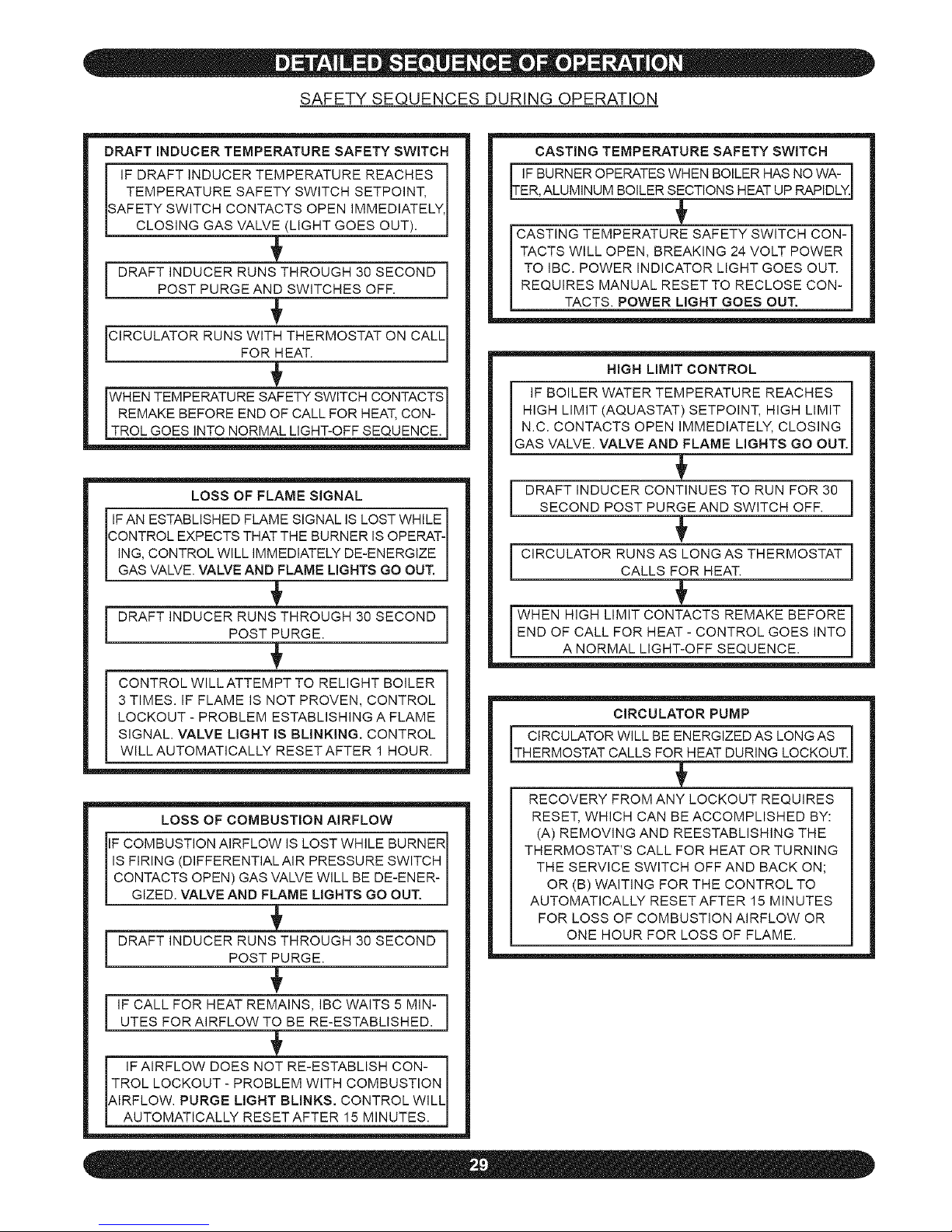
SAFETY SEQUENCES DURING OPERATION
DRAFT INDUCER TEMPERATURE SAFETY SWITCH
IF DRAFT INDUCER TEMPERATURE REACHES i
TEMPERATURE SAFETY SWITCH SETPOINT,
/
SAFETY SWITCH CONTACTS OPEN IMMEDIATELY, I
[ CLOS NG GAS VALVE_ (L GHT GOES OUT). J
[ ]
POST PURGE AND SWITCHES OFF.
FOR_HEAT.
rWHENTEMPERATURESAFETYSWITCHCONTACTS
EMAKE BEFORE END OF CALL FOR HEAT, CON- I
[TROL GOES NTO NORMAL L GHT-OFF SEQUENCE.J
LOSS OF FLAME SIGNAL
IF AN ESTABLISHED FLAME SIGNAL IS LOST WHILE
CONTROL EXPECTS THAT THE BURNER IS OPERAT-
ING, CONTROL WILL IMMEDIATELY DE-ENERGIZE
GAS VALVE. VALVE AND FLAME L GHTS GO OUT.
CONTROL WILLATTEMPT TO RELIGHT BOILER
3 TIMES. IF FLAME IS NOT PROVEN, CONTROL
LOCKOUT - PROBLEM ESTABLISHING A FLAME
SIGNAL. VALVE LIGHT IS BLINKING, CONTROL
WILL AUTOMATICALLY RESET AFTER 1 HOUR.
LOSS OF COMBUSTION AIRFLOW
iF COMBUSTION AIRFLOW IS LOST WHILE BURNER
IS FIRING (DIFFERENTIALAIR PRESSURE SWITCH
CONTACTS OPEN) GAS VALVE WILL BE DE-ENER-
G ZED. VALVE AND FLAME L GHTS GO OUT.
[
!
UTES FOR AIRFLOW TO BE RE-ESTABLISHED.
IF AIRFLOW DOES NOT RE-ESTABLISH CON-
TROL LOCKOUT - PROBLEM WITH COMBUSTION
AIRFLOW. PURGE LIGHT BLINKS. CONTROL WILL I
[ AUTOMAT CALLY RESETAFTER 15 M NUTES. J
CASTING TEMPERATURE SAFETY SWITCH
IF BURNER OPERATES WHEN BOILER HAS NO WA- i
/
ER, ALUMINUM BOILER SECTIONS HEAT UP RAPIDLY.J
CASTING TEMPERATURE SAFETY SWITCH CON-
TACTS WILL OPEN, BREAKING 24 VOLT POWER
TO IBC. POWER INDICATOR LIGHT GOES OUT.
REQUIRES MANUAL RESET TO RECLOSE CON-
TACTS. POWER LIGHT GOES OUT.
HIGH LIMIT CONTROL
IF BOILER WATER TEMPERATURE REACHES i
HIGH LIMIT (AQUASTAT) SETPOINT, HIGH LIMIT
/
N.C. CONTACTS OPEN IMMEDIATELY, CLOSING
GAS VALVE. VALVE AND FLAME L GHTS GO OUT.J
DRAFT INDUCER CONTINUES TO RUN FOR 30 |
SECOND POST PURGE AND SWITCH OFF.
!
CIRCULATOR RUNS AS LONG AS THERMOSTAT |
CALLS FOR HEAT.
!
WHEN HIGH LIMIT CONTACTS REMAKE BEFORE]
END OF CALL FOR HEAT - CONTROL GOES INTO
A NORMAL L GHT-OFF SEQUENCE. J
CIRCULATOR PUMP
CIRCULATOR WILL BE ENERGIZED AS LONG AS
THERMOSTAT CALLS FOR_HEAT DUR NG LOCKOUT.]
RECOVERY FROM ANY LOCKOUT REQUIRES
RESET, WHICH CAN BE ACCOMPLISHED BY:
(A) REMOVING AND REESTABLISHING THE
THERMOSTATS CALL FOR HEAT OR TURNING
THE SERVICE SWITCH OFF AND BACK ON;
OR (B) WAITING FOR THE CONTROL TO
AUTOMATICALLY RESETAFTER 15 MINUTES
FOR LOSS OF COMBUSTION AIRFLOW OR
ONE HOUR FOR LOSS OF FLAME.
Page 30

END OF NORMAL SEQUENCE OF OPERATION
THERMOSTAT ENDS CALL FOR HEAT.
GAS VALVE AND CIRCULATOR PUMP ARE DE-ENER-
GIZED, VALVE AND FLAME LIGHTS GO OUT.
BLOWER RUNS FOR 30 SECONDS POST PURGE,
PURGE LIGHT IS ON.
BLOWER IS DE-ENERGIZED AFTER 30 SECONDS,
PURGE LIGHT SHUTS OFF.
BOILER STAND BY FOR NEXT CALL FOR HEAT.
Page 31
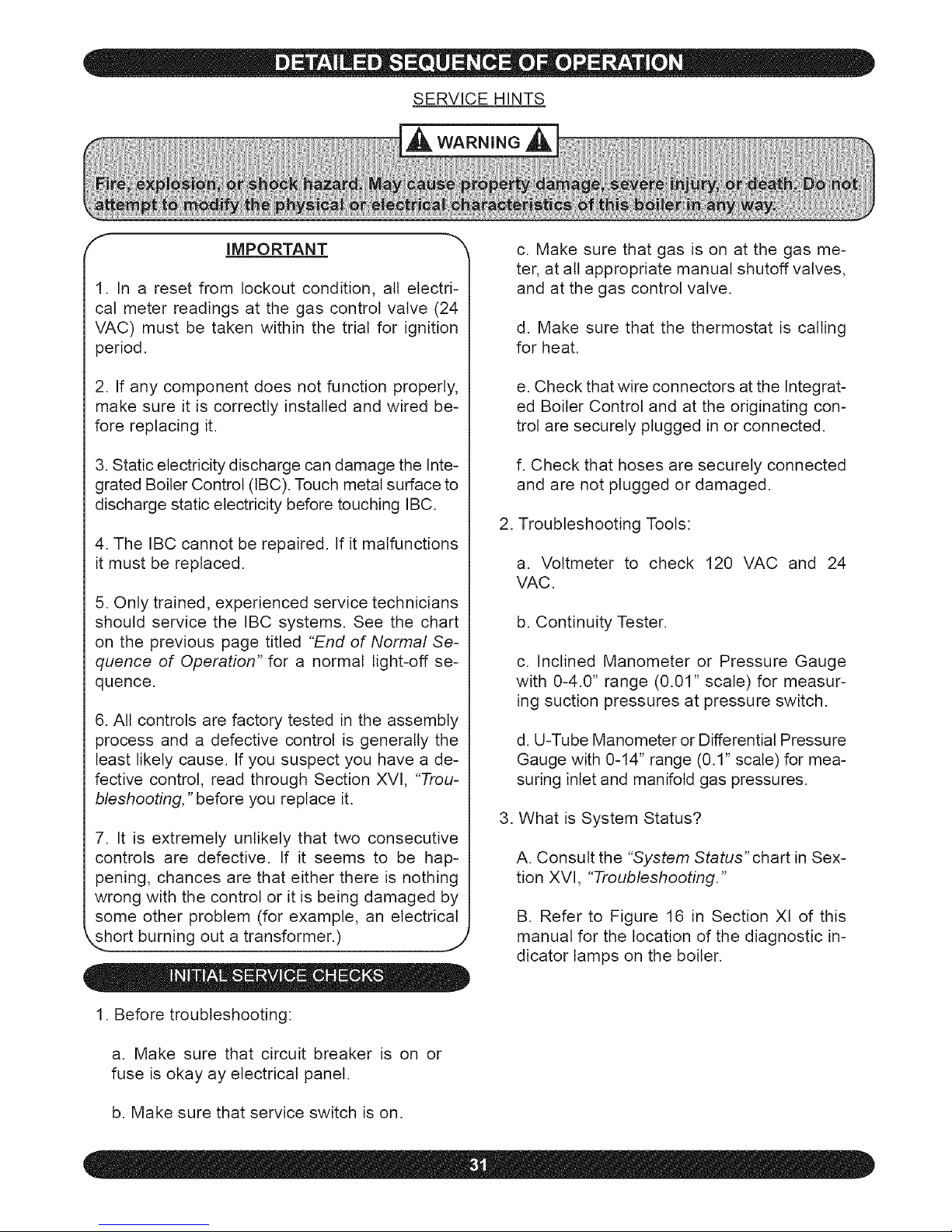
SERVICE HINTS
,_ WARNING ,_k
f- IMPORTANT
1. In a reset from lockout condition, all electri-
cal meter readings at the gas control valve (24
VAC) must be taken within the trial for ignition
period.
2. If any component does not function properly,
make sure it is correctly installed and wired be-
fore replacing it.
3. Static electricity discharge can damage the Inte-
grated Boiler Control (IBC). Touch metal surface to
discharge static electricity before touching IBC.
4. The IBC cannot be repaired. If it malfunctions
it must be replaced.
5. Only trained, experienced service technicians
should service the IBC systems. See the chart
on the previous page titled "End of Normal Se-
quence of Operation" for a normal light-off se-
quence.
6. All controls are factory tested in the assembly
process and a defective control is generally the
least likely cause. If you suspect you have a de-
fective control, read through Section XVI, "Trou-
bleshooting," before you replace it.
7. It is extremely unlikely that two consecutive
controls are defective. If it seems to be hap-
pening, chances are that either there is nothing
wrong with the control or it is being damaged by
some other problem (for example, an electrical
short burning out a transformer.) ,,,
1. Before troubleshooting:
a. Make sure that circuit breaker is on or
fuse is okay ay electrical panel.
b. Make sure that service switch is on.
c. Make sure that gas is on at the gas me-
ter, at all appropriate manual shutoff valves,
and at the gas control valve.
d. Make sure that the thermostat is calling
for heat.
e. Check that wire connectors at the Integrat-
ed Boiler Control and at the originating con-
trol are securely plugged in or connected.
f. Check that hoses are securely connected
and are not plugged or damaged.
2. Troubleshooting Tools:
a. Voltmeter to check 120 VAC and 24
VAC.
b. Continuity Tester.
c. Inclined Manometer or Pressure Gauge
with 0-4.0" range (0.01" scale) for measur-
ing suction pressures at pressure switch.
d. U-Tube Manometer or Differential Pressure
Gauge with 0-14" range (0.1" scale) for mea-
suring inlet and manifold gas pressures.
3. What is System Status?
A. Consult the "System Status" chart in Sex-
tion XVI, "Troubleshooting."
B. Refer to Figure 16 in Section Xl of this
manual for the location of the diagnostic in-
dicator lamps on the boiler.
Page 32

SERVICE HINTS
The differential air pressure switch is a
safety device which will prevent the boiler
from firing if there is an air intake, boiler
heat exchanger or vent blockage.
1. Turn off service switch, or lower ther-
mostat setting.
2. Remove vinyl caps from Tee.
3. Install testing lines as shown to inclined
manometer or differential pressure gauge
with the ability to read 0.01" to at least
6.0" w.c.
4. Turn on service switch and set ther-
mostat to call for heat.
5. If manometer readings do not corre-
spond to the chart at right, check for
possible causes:
• Blockage or moisture in suction
lines to switch.
• Blockage or moisture in orifice in-
stalled in suction lines to switch.
• Blockage in air intake or vent
pipes.
• Undersized air intake or vent
pipes.
• Loose blower wheel on motor
shaft.
• Incorrect pressure switch or pres-
sure switch setpoint.
• Gas valve out of adjustment.
6. When pressure reading is proper and
the pressure switch is operating prop-
erly, remove testing lines and reinstall
vinyl caps to Tee and 3-way connector.
This diagram indicates the locations of the connection
points required to check the differential air pressure.
DIFFERENTEAL AIR
TRANSPARENT WHITE
SILICONE HOSE
\
SIGHT GLASS
&: ADAPTER
DRANGE SELECONE HOSE
TESTING
LINES GAS VALVE
MANOMETER
Not Running 0" 3.5" Closed
0.5" Open
Running With- 1.00" for Model 125 3.5" Closed
out Blockage 1.50" for Model 150 0.5" Closed
(Approximate
rain. vent 1.50" for Model 175
lengths) 2.00" for Model 200
Running With Greater Than or Equal 3.5" Open
Blockage To Setpoints 0.5" Closed
Page 33

SYSTEM STATUS
The indicator lights track the operating sequence If the system locks out, the lights indicate the point in
the sequence of operation were lockout occurs If this table does not readily provide the reason for boiler
malfunction or non-operation, refer to the following pages for more detailed troubleshooting procedures
LIGHT STATUS INDICATES
On IBC is energized through 24 volt transformer
POWER Off IBC is not energized
Blinking IBC receives more than 40 VAC
On IBC is energizing the draft inducer and air flow is proven
Off during purge cycle - draft inducer is not powered on or air flow is not proven
Off
PURGE Off during igniter and run cycle - normal operation, purge cycle complete
IBC is locked out Problem could indicate false positive proof of air flow Blocked vent,
Blinking intake air pipe, flue way, or orifice in negative pressure hose
On IBC is energizing igniter
IGNITER
Off Igniter is not energized
On IBC is energizing gas control valve to open
Off Gas control valve is closed
VALVE
IBC is locked out Problem isflame has not been proven in three (3) ignitionattempts
Blinking May be due to broken igniter or lack of/low flame signal, or no gas
On Bright Flame proven
FLAME On Dim Checking for flame signal (during trial for ignition)
Off Flame unproven
ELECTRICAL SHOCK HAZARD MAY CAUSE SERIOUS iNJURY OR DEATH.
The following procedures may expose you to dangerous line voltage. Use caution to avoid touching
live electrical contacts. Service must be performed by a trained, experienced service technician.
WHAT TO DO IF YOU SMELL GAS:
• Do not try to light any appliance.
=Do not touch any electric switch or use any phone in the building.
• Immediately call your gas supplier from a neighbor's phone. Follow the gas supplier's
instructions.
• If you can not contact your gas supplier, call the fire department.
Should overheating occur orthe gas supply fail to shut off, do not turn off or disconnect the elec-
trical supply to the pump. Instead, shut off the gas at a location external to the appHcance.
Do not use the boiler if any part of the gas control system has been under water. A qualified
service technician should inspect the boiler and replace any part of the control system and any
gas control which has been under water.
Use only your hand to turn the gas control knob. Never use tools. If the knob will not turn by hand,
don't try to repair it. Force or attempted repair may result in a fire or explosion.
,. j
Page 34
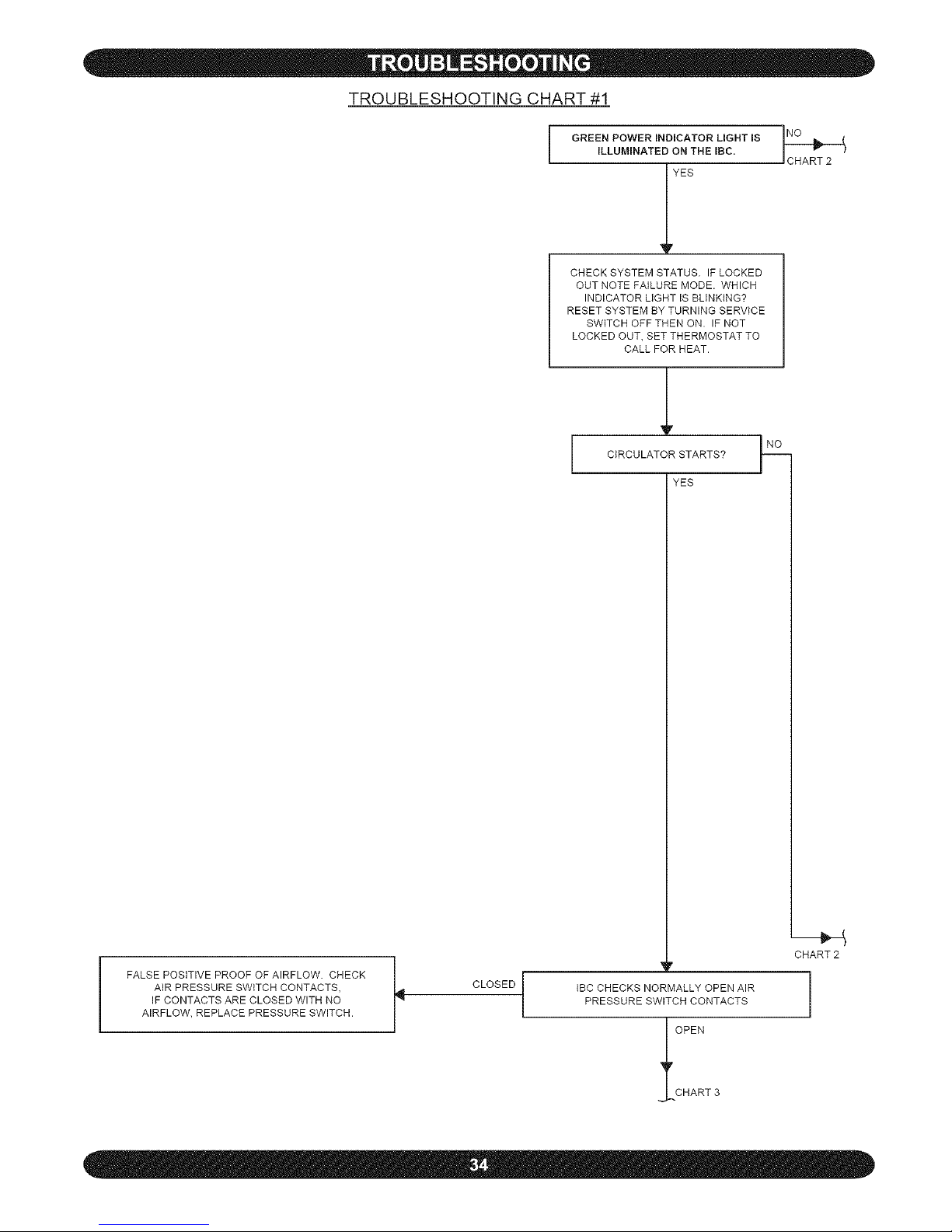
TROUBLESHOOTING CHART #1
GREEN POWER INDICATOR LIGHT IS
iLLUMINATED ON THE IBC.
_7 YES
CHECK SYSTEM STATUS. IF LOCKED
OUT NOTE FAILURE MODE. WHICH
INDICATOR LIGHT IS BLINKING?
RESET SYSTEM BY TURNING SERVICE
SWITCH OFF THEN ON. IF NOT
LOCKED OUT, SET THERMOSTAT TO
CALL FOR HEAT.
CIRCULATOR STARTS?
YES
FALSE POSITIVE PROOF OF AIRFLOW. CHECK
AIR PRESSURE SWITCH CONTACTS,
IF CONTACTS ARE CLOSED WITH NO
AIRFLOW, REPLACE PRESSURE SWITCH.
CLOSED
CHART2
_r
MALLY OPENAI_
CH CONTACTS
OPEN
CHART3
Page 35
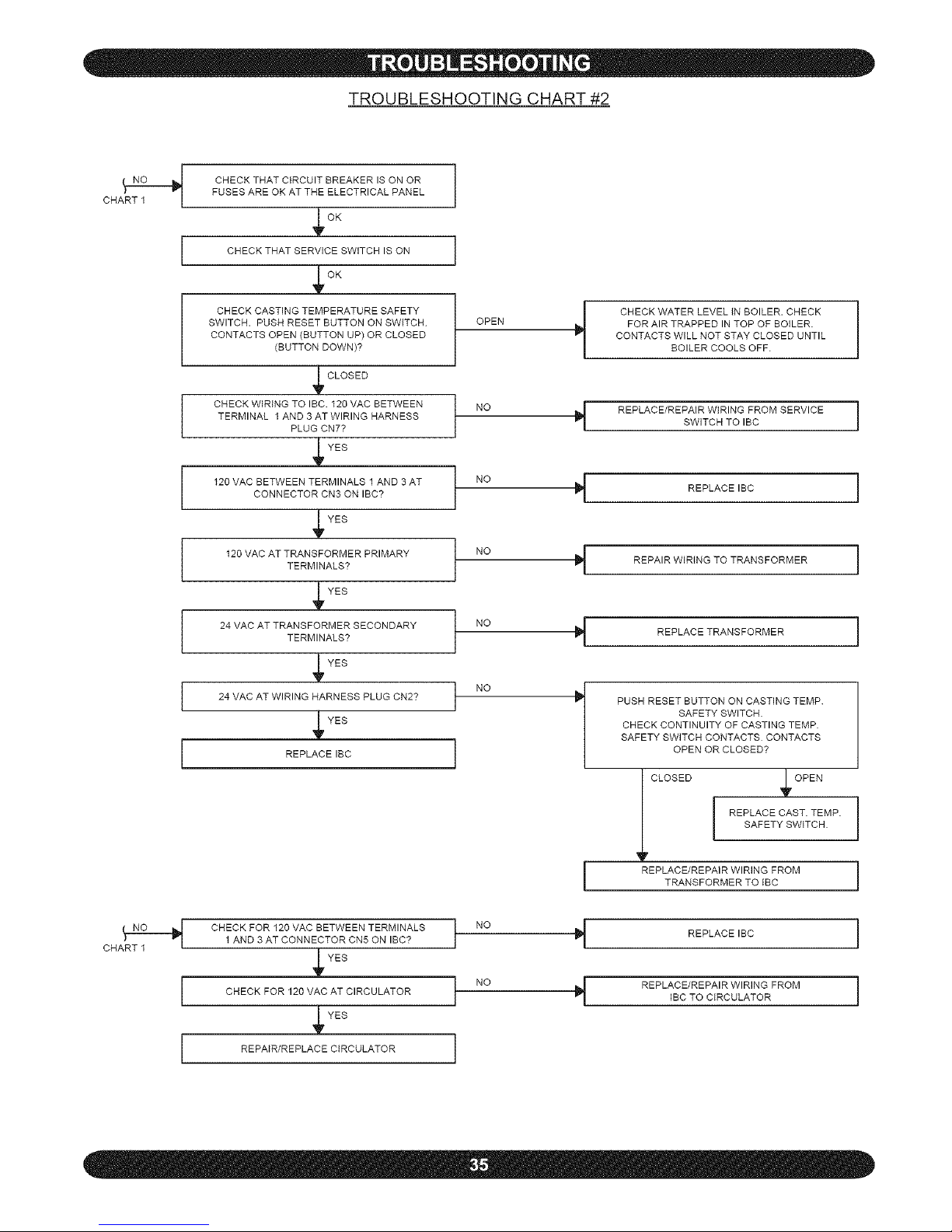
TROUBLESHOOTING CHART #2
CHART I
CHECK THAT CIRCUIT BREAKER IS ON OR
FUSES ARE OK AT THE ELECTRICAL PANEL
, GK
CHECK THAT SERVICE SWITCH IS ON
CHECK CASTING TEMPERATURE SAFETY
SWITCH. PUSH RESET BUTTON ON SWITCH
CONTACTS OPEN (BUTTON UP) OR CLOSED
(BUTTON DOWN)?
OPEN
_ CLOSED
CHECK WIRING TO IBC. 120 VAC BETWEEN NO
TERMINAL 1AND 3 AT WIRING HARNESS
PLUG CN7?
YES
120 VAC BETWEEN TERMINALS 1 AND 3 AT NOCONNECTOR CN3 ON IBC?
V YES
120 VAC AT TRANSFORMERTERMINALS?PRIMARY NO _-
yYES
24 VAC AT TRANSFORMERTERMINALS?SECONDARY NO
V YES
24 VAC AT WIRING HARNESS PLUG CN2? NO
_YES
]
REPLACE IBC I
CHECK FOR 120 VAC BETWEEN TERMINALS t NO1 AND 3 AT CONNECTOR CN5 ON IBC?
YES
CHECK FOR 120 VAC AT CIRCULATOR t NO
r YES
REPAiR/REPLACE CIRCULATOR I
l
CHECK WATER LEVEL IN BOILER. CHECK
FOR AIR TRAPPED IN TOP OF BOILER.
CONTACTS WILL NOT STAY CLOSED UNTIL
BOILER COOLS OFF.
REPLACE/REPAIR WIRING FROM SERVICE |
I
SWITCH TO IBC
REPLACE IBC
i
REPAIR WiRiNG TO TRANSFORMER 1
REPLACE TRANSFORMER i
PUSH RESET BUTTON ON CASTING TEMP.
SAFETY SWITCH.
CHECK CONTINUITY OF CASTING TEMP.
SAFETY SWITCH CONTACTS CONTACTS
OPEN OR CLOSED?
I CLOSED l _pOPEN
REPLACE/REPAIR WIRING FROM
TRANSFORMERTOtBC
REPLACE IBC
REPLACE/REPAIR WIRING FROM
iBC TO CIRCULATOR
1
I
i
Page 36

CHART1
OPEN
/
l BLOWER STARTS
YES
_V
l PURGE LIGHT ON?
YES
_v
15 SECOND PRE PURGE COMPLETE
PURGE LIGHT IS OFF SIMULTANEOUSLY
IGNITOR LIGHT iS ON AS IGNITOR CIRCUIT
IS ENERGIZED.
TROUBLESHOOTING CHART #3
J_ CHECK FOR VAC
BETWEEN TERMINALS 1 AND 3
AT CONNECTOR CN4 ON IBC
YES
CHECK FOR 120 VAC AT
BLOWER LEADS ON WIRING
HARNESS
YES
REPAIR/REPLACE
BLOWER
IBC WAITS UP TO 5
MINUTES FOR NORMALLY
OPEN AIR
PRESSURE SWITCH
CONTACTS TO CLOSE,
INDICATING BLOWER
SUCTION IS
PRESENT
1_ REPLACEIBC
REPAIR/REPLACE
WIRING FROM IBC
TO BLOWER
J
PRESSURE SWITCH
_ ONTACTS
OPEN
I
ARE ORIFICE IN
NEGATIVE PRESSURE
HOSE CLEAR?
YES
ARE VENT PIPE AND AIR
INTAKE PIPE CLEAR
(NO BLOCKAGE)
YES
CHECK AIR
PRESSURE SWITCH PER
INSTRUCTIONS ON
FOLLOWING PAGES. ARE
SAMPLING LINES CLEAR
AND CONNECTED
PROPERLY?
YES
CHECK FLUE PASSAGES
IN BOILER PER
"MAINTENACE AND
CLEANING" ARE FLUE
PASSAGES IN BOILER CLEAN?
YES
CHECK DRAFTINDUCER
MOTOR RPM. ISIT
3400-3600?
YES
CHECKFOR BROKEN OR
LOOSEIMPELLER ON DRAFT
INDUCER AND REPLACE
BLOWERIFFOUND TO
BE BROKEN OR LOOSE
I_ REPLACE IBC ]
]
CLEAN OUT BLOCKAGE
AT ORIFICE
CLEAN OUT VENT PIPE
AND/OR AIR INTAKE PIPE
CHECK FOR SAGS OR
LOW SPOTS WHERE
CONDENSATE MAY
PUDDLE AND BLOCK
THE VENT
NO_ CLEAN OUT SAMPLING
LINES OR REPLACE
DEFECTIVE SWITCH
CLEAN BOILER FLUE
PASSAGES PER
MAINTENANCEAND
CLEANINGINSTRUCTIONS
REPLACE
BLOWER
Page 37
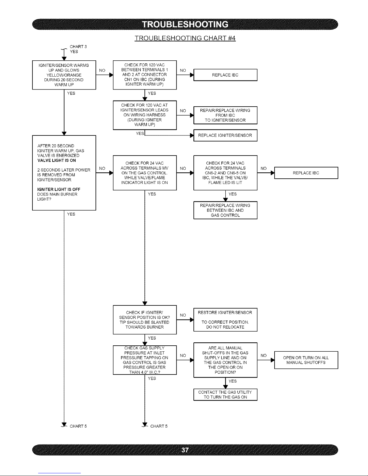
CHART3
'YES
IGNITER/SENSORWARMS_
UP AND GLOWS
YELLOW/ORANGE
DURING 20 SECOND
WARM UP
YES
_r
AFTER 20 SECOND
IGNITER WARM UP, GAS
VALVE tS ENERGIZED
VALVE LIGHT IS ON
2 SECONDS LATER POWER
IS REMOVED FROM
IGNITER/SENSOR
IGNITER LIGHT IS OFF
DOES MAIN BURNER
LIGHT?
YES
TROUBLESHOOTING CHART #4
CHECK FOR 120 VAC
BETWEEN TERMINALS 1
AND 2 AT CONNECTOR
CN1 ON IBC (DURING
IGNITER WARM UP)
YES
CHECK FOR 120 VAC AT
IGNITER/SENSOR LEADS
ON WIRING HARNESS
(DURING iGNITER
WARM UP)
YESI
CHECK FOR 24 VAC
ACROSS TERMINALS MV
ON THE GAS CONTROL.
WHILE VALVE/FLAME
INDICATOR LIGHT IS ON
-_ REPLACEIBC
___ REPAIR/REPLACE WIRING
FROM IBC
TO IGNITER/SENSOR
REPLACE IGNITER/SENSOR
YES
y
CHECK FOR 24 VAC
ACROSS TERMINALS
CN6-2 AND CN6-5 ON
tgc, WHILE THE VALVE/
FLAME LED IS LIT
YES
REPAIR/REPLACE WiRiNG
BETWEEN IBC AND
GAS CONTROL
CHECKIFIGNITER/ H
SENSOR POSITIONIS OK?
TIP SHOULD BE SLANTED
TOWARDSBURNER
YES
/
CHECK GAS SUPPLY II
PRESSURE ATINLET
PRESSURE TAPPING ON
GAS CONTROLIS GAS
PRESSURE GREATER
THAN 4.0"W.C.?
YES
CHART5 CHART5
RESTORE IGNiTER/SENSOR
TO CORRECT POSITION.
DO NOT RELOCATE
/
ARE ALL MANUAL /
SHUT-OFFS IN THE GAS
SUPPLY LINE AND ON
THE GAS CONTROL tN
THE OPEN OR ON
POSITION?
YES
CONTACT THE GAS UTILITY
TO TURN THE GAS ON
REPLACEtBC
OPEN OR TURN ON ALL
MANUALSHUTOFFS
Page 38
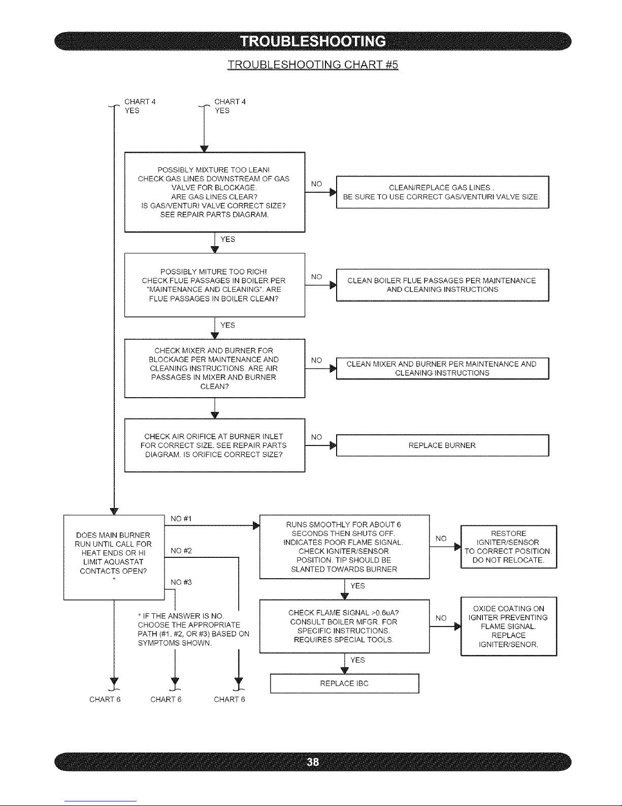
TROUBLESHOOTING CHART #5
CHART4
YES
CHART4
YES
POSSIBLY MIXTURE TOO LEAN!
CHECK GAS LINES DOWNSTREAM OF GAS
VALVE FOR BLOCKAGE.
ARE GAS LINES CLEAR?
IS GAS/VENTURI VALVE CORRECT SIZE?
SEE REPAIR PARTS DIAGRAM.
_V YES
POSSIBLY MITURE TOO RICH!
CHECK FLUE PASSAGES IN BOILER PER
"MAINTENANCE AND CLEANING". ARE
FLUE PASSAGES IN BOILER CLEAN?
YES
CHECK MIXERANDBURNERFOR
BLOCKAGE PER MAINTENANCE AND
CLEANINGINSTRUCTIONS. ARE AIR
PASSAGESIN MIXER AND BURNER
CLEAN?
CHECK AIR ORIFICE AT BURNER INLET
FOR CORRECT SIZE. SEE REPAIR PARTS
DIAGRAM. IS ORIFICE CORRECT SIZE?
CLEAN/REPLACE GAS LINES .
BE SURE TO USE CORRECT GAS/VENTURI VALVE SIZE.
CLEAN BOILER FLUE PASSAGES PER MAINTENANCE
AND CLEANING INSTRUCTIONS
CLEAN MIXER AND BURNER PER MAINTENANCE AND 1
CLEANING INSTRUCTIONS
REPLACE BURNER !
DOES MAIN BURNER
RUN UNTIL CALL FOR
HEAT ENDS OR HI
LIMIT AQUASTAT
CONTACTS OPEN?
r
CHART 6
NO #1
NO #2
NO #3
IF THE ANSWER IS NO.
CHOOSE THE APPROPRIATE
PATH (#!_ #2, OR #3) BASED ON
SYMPTOMS SHOWN.
CHART 6 CHART 6
RUNS SMOOTHLY FOR ABOUT 6
SECONDS THEN SHUTS OFF.
INDICATES POOR FLAME SIGNAL.
CHECK IGNITER/SENSOR
POSITION. TIP SHOULD BE
SLANTED TOWARDS BURNER
YES
CHECK FLAME SIGNAL >0.6uA?
CONSULT BOILER MFGR. FOR
SPECIFIC INSTRUCTIONS.
REQUIRES SPECIAL TOOLS.
YES
REPLACE IBC
H RESTORE 1
IGNITER/SENSOR
TO CORRECT POSITION.
DO NOT RELOCATE.
_t OXIDE COATING ON
IGNITER PREVENTING
FLAME SIGNAL.
REPLACE
IGNITER/SENOR.
1
Page 39
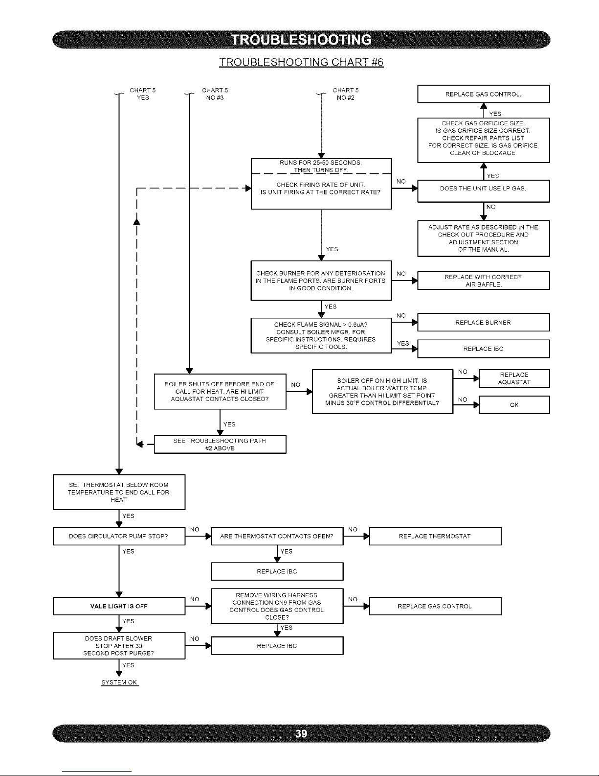
TROUBLESHOOTING CHART #6
CHART5
YES
I
I
CHART 5
NO #3 CHART 5 I
f RUNS FOR 25-50 SECONDS.
THEN TURNS OFF.
CHECK FIRING RATE OF UNIT.
IS UNIT FIRING AT THE CORRECT RATE?
_V YEs
I CHECK BURNER FOR ANY DETERIORATION I_ _
IN THE FLAME PORTS. ARE BURNER PORTS
IN GOOD CONDITION.
YES
l CHECK FLAME SIGNAL > 0.6uA? N_E_S
CONSULT BOILER MFGR. FOR
SPECIFIC INSTRUCTIONS REQUIRES
SPECIFIC TOOLS
BOILER SHUTS OFF BEFORE END OF
CALL FOR HEAT. ARE HI LIMIT
AQUASTAT CONTACTS CLOSED?
YES
SEE TROUBLESHOOTING PATH
#2 ABOVE
BOILER OFF ON HIGH LIMIT. IS
ACTUAL BOILER WATER TEMP.
GREATER THAN HI LIMIT SET POINT
MINUS 30°F CONTROL DIFFERENTIAL?
REPLACE GAS CONTROL.
rYES
CHECK GAS ORFICICE SIZE.
IS GAS ORIFICE StZE CORRECT,
CHECK REPAIR PARTS LIST
FOR CORRECT SIZE. IS GAS ORIFICE
CLEAR OF BLOCKAGE,
rYES
DOES THE UNIT USE LP GAS.
NO
ADJUSTRATEASDESCRIBEDINTHE
CHECK OUT PROCEDURE AND
ADJUSTMENT SECTION
OF THE MANUAL.
REPLACE WITHCORRECT
AIR BAFFLE
REPLACEBURNER
REPLACEIBC
NNNo_ REPLACE
AQUASTAT
OK
I
I
I
I
I
I
SET THERMOSTAT BELOW ROOM
TEMPERATURE TO END CALLFOR
HEAT
YEB
DOES CIRCULATOR PUMP STOP?
I VALE LIGHT IS OFF
YEB
DOES DRAFT BLOWER
STOP AFTER 30
SECOND POST PURGE?
YEB
SYSTEM OK
_ ARE THERMOSTAT CONTACTS OPEN? I--_ REPLACE THERMOSTAT ]
YES
l REPLACE IBC I
i_ REMOVE WIRING HARNESS I_ _ ]
CONNECTION CA9 FROM GAS REPLACE GAS CONTROL
CONTROL DOES GAS CONTROL
CLOSE?
_YES
I--_ REPLACEIBC I
Page 40

Boiler Model Serial # Date Installed
Measured BTU/HR Input
o Installation instructions have been followed
o Checkout procedure and adjustments performed
o Maintenance and Service issues reviewed with owner/maintenance person
o Installation booklet affixed on or adjacent to boiler
Installer (Company)
Address
Phone
Installer's Name
Signature
\
 Loading...