

Dunkirk PWXL Installation, Operation & Maintenance Manual
R
PWXL
Cast Iron Gas Fired
Hot Water Boilers
INSTALLATION, OPERATION &
MAINTENANCE MANUAL
An ISO 9001-2000 Certified Company
DUNKIRK BOILERS
85 Middle Rd.
Dunkirk, NY 14048
www.dunkirk.com
P/N 240007958 REV A [09/09]

H
TABLE OF CONTENTS
Safety Symbols........................................................................................................................................................4
Boiler Ratings and Capacities ................................................................................................................................5
Before You Start ......................................................................................................................................................6
Locating the Boiler .................................................................................................................................................7
Combustion And Ventilation Air ............................................................................................................................8
System Piping ...................................................................................................................................................... 11
Chimney and Vent Pipe Operation ..................................................................................................................... 13
Vent Damper Operation ...................................................................................................................................... 14
Gas Supply Piping ................................................................................................................................................ 16
Electrical Wiring ................................................................................................................................................... 17
Equipment and Optional Accessories ................................................................................................................ 21
Starting the Boiler ............................................................................................................................................... 22
Initial Operational Boiler Test Check-Out Procedure ........................................................................................ 24
Initial Operational Boiler Test Check-Out Certicate & Signed Receipt .......................................................... 25
Operating Your Boiler .......................................................................................................................................... 26
Checking and Adjusting ...................................................................................................................................... 27
Maintaining Your Boiler ...................................................................................................................................... 27
Sequence of Operation ........................................................................................................................................ 28
Troubleshooting .................................................................................................................................................. 29
Hydrolevel Hydrostat Model 3100 ..................................................................................................................... 29
Service Hints......................................................................................................................................................... 30
C.S.A. Certied for
Natural gas or Propane
Tested for 50 LB. ASME
Working Pressure
2

SAFETY SYMBOLS
The following dened symbols are used throughout this manual to notify the reader of potential hazards of varying risk
levels.
DANGER
Indicates an imminently hazardous situation which, if not
!
avoided, WILL result in death, serious injury or substantial
property damage.
WARNING
Indicates an imminently hazardous situation which, if not
!
avoided, may result in death, serious injury or substantial
property damage.
IMPORTANT: Read the following instructions COMPLETELY before installing!
CAUTION
!
Indicates an imminently hazardous situation which, if not
avoided, may result in injury or property damage.
NOTICE
Indicates information which should be followed to ensure
proper installation and operation.
NOTICE
ese Instruction must be axed on or adjacent to the
boiler. Retain for future reference.
WARNING
All installations of boilers and venting should be done only
by a qualied expert and in accordance with the appropriate manual. Installing or venting a boiler or any other gas
!
appliance with improper methods or materials may result
in serious injury or death due to re or to asphyxiation
from poisonous gases such as carbon monoxide which is
odorless and invisible.
WARNING
Keep boiler area clear and free from combustible materials,
gasoline and other ammable vapors and liquids.
DO NOT obstruct air openings to the boiler room.
Modication, substitution or elimination of factory
equipped, supplied or specied components may result in
property damage, personal injury or the loss of life.
!
TO THE OWNER - Installation and service of this boiler
must be performed by a qualied installer.
TO THE INSTALLER - Leave all instructions with the
boiler for future reference.
When this product is installed in the Commonwealth of
Massachusetts the installation must be performed by a
Licensed Plumber or Licensed Gas Fitter.
3
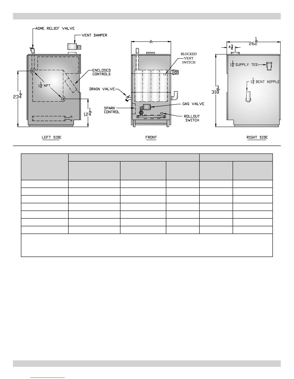
Table 1- Boiler Ratings and Capacities
Number of Boiler
Sections
AGA Input *MBH
BOILER RATINGS AND CAPACITIES
Natural or Propane Gas Dimensions
Heating Capacity
*MBH+
Net I=B=R
Rating *MBH
Flue Diameter Dim. A
3 70 57 50 5" 11-1/4"
4 105 85 74 6" 14-1/2"
5 140 113 98 6" 17-3/4"
6 175 142 123 7" 21"
7 210 170 148 7" 24-1/4"
8 245 198 172 7" 27-1/2"
9 280 226 197 7" 30-3/4"
* MBH = 1,000 BTUH = British ermal Unit Per Hour. Boilers are equipped for altitudes up to 2,000 feet only. For altitudes
above 2,000 feet, ratings should be reduced at the rate of 4% for each 1,000 feet above sea level.
+ Heating Capacity based on D.O.E. (Department of Energy) test procedure.
New York City MEA Number 484-84 E Vol. IV.
e Ratings marked “Net I=B=R Ratings” indicate the amount of
remaining heat input that can be used to heat the radiation units.
e net I=B=R Ratings shown are based on an allowance of 1.15
in accordance with the factors shown on the I=B=R Standard as
published by the Hydronics Institute. Selection of boiler size should
be based upon “Net I=B=R Rating” being equal to or greater than
the calculated heat loss of the building. e Manufacturer should be
consulted before selecting a boiler for installations having unusual
piping and pickup requirements.
Boilers For Use At High Altitude
is boiler is factory equipped for use at altitudes of 0-2,000 feet
above sea level. For use at altitudes above sea level, the input ratings
are reduced by a change in main orice size.
For altitudes above 2,000 feet above sea level, input ratings should be
reduced at the rate of 4% for each 1,000 feet above sea level. Consult
the latest edition of the National Fuel Gas Code (NFPA54/ANSI
Z223.1) for correct orice sizing information. High altitude orices
are available from the boiler manufacturer.
4

BEFORE YOU START
Check to be sure you have the right size boiler before starting the
installation. See rating and capacity table on previous page. Also be
sure the new boiler is for the type of gas you are using. Check the
rating plate on the right side of the boiler.
You must see that the boiler is supplied with the correct type of gas,
fresh air for combustion, and a suitable electrical supply. e boiler
must be connected to a suitable venting system and an adequate piping system. A thermostat, properly located, is needed for control of
the heating system. If you have any doubts as to the various requirements, check with local authorities. Take the time to complete all of
the steps for SAFE and PROPER operation of the heating system.
If this boiler is installed in a building under construction, special
care must be taken to insure a clean combustion air supply during
the construction process. Airborne particulates such as from drywall dust and from berglass insulation can clog the burner ports,
ueway passages and cause incomplete combustion and sooting.
Where required by the authority having jurisdiction, the installation
must conform to American Society of Mechanical Engineers Safety
Code for Controls and Safety Devices for Automatically Fired Boilers, No. CSD-1.
e installation must conform to the requirements of the authority
having jurisdiction or, in the absence of such requirements, to the
National Fuel Gas Code, ANSI Z223.1-latest revision.
Installers - Follow local regulations with respect to installation of CO
detectors. Follow maintenance recommendations in this instruction
manual.
WARNING
Keep boiler area clean and free from combustible materi-
!
als, gasoline and other ammable vapors and liquids. Failure to keep boiler area clean may result in death, serious
injury, or substantial property damage.
5
LOCATING THE BOILER
Select level location as centralized with piping system, and as
1.
near chimney as possible.
Place crated boiler at selected location, remove crate by pulling
2.
crate sides from top and bottom boards.
is boiler must be set on non-combustible oor or optional
3.
non-combustible Base Plate placed over the top of a combustible oor. Refer to Repair Parts and Optional Kits for additional
detals (3-6 section Boiler Base Plate Part #14614031; or 7-9
Section Boiler base Plate Part #14614032). A combustible oor
is dened as materials made of or surfaced with wood, compressed paper, plant bers, or other materials that are capable
of being ignited and burned. Such material shall be considered
combustible even thought ame-proofed, re-retardant treated,
or plastered. is boiler must not be installed on carpeting.
Boiler is to be level. Metal shims may be used under base legs
4.
for nal leveling.
Additional clearance for service may exceed clearance for re
5.
protection. Always comply with the minimum re protection
clearance shown on the boiler. An 18 inch clearance should
be maintained on any side where passage is required to access
another side for cleaning, servicing, inspection or replacement
of any part that may need attention.
To determine minimum clearances to combustibles refer to Ta-
6.
ble 2b, for rooms with a single boiler only. Rooms that are large
in comparison with the size of the boiler are dened as rooms
having a volume equal to or greater than 16 times the volume of
the boiler. Where the actual ceiling height of a room is greater
that 8’ the volume of a room shall be gured on the basis of a
ceiling height of 8’. Determination of room size should be based
on the total volume of all gas red equipment install in the
room. Consult the latest revision of the National Fuel Gas Code
for further information.
Equipment shall be installed in a location in which the facilities
7.
for ventilation permit satisfactory combustion of gas, proper
venting, and maintenance of ambient temperature at safe limits
under normal conditions of use. Equipment shall be located so
as not to interfere with proper circulation of air. When normal
inltration does not provide the necessary air, outside air shall
be introduced.
Advise owner to keep air passages free of obstructions. Ven-
8.
(See “Combustion and Ventilation Air”)
tilating and combustion air must enter boiler room without
restrictions.
e boiler shall be installed such that the automatic gas ignition
9.
system components are protected from water (dripping, spraying, rain, etc.) during appliance operation and service (condensate trap, control replacement, etc.).
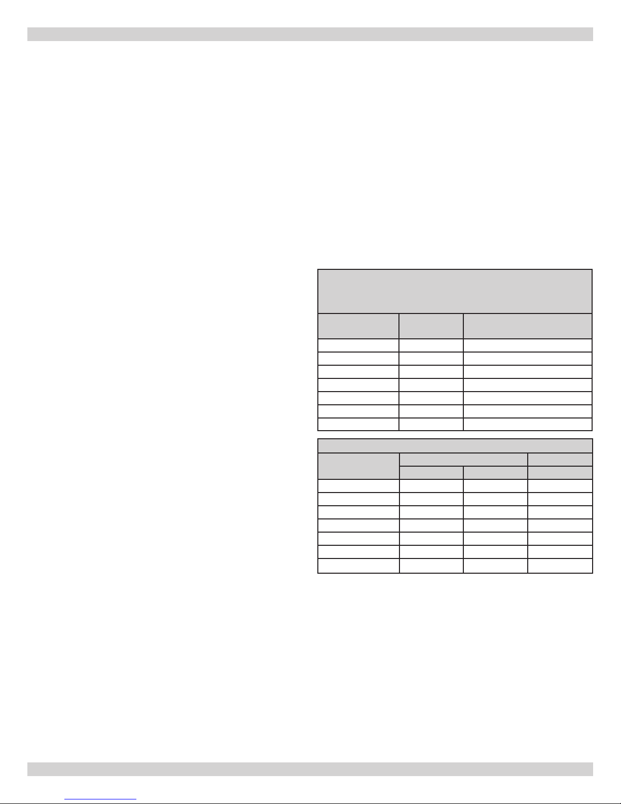
Table 2a - Determination of Room Size
If room does not contain mimimum volume shown to be considered a
Large Room, use "Small Room or Alcove" values.
Boiler Size Volume (Ft3)
3 Section 5.4 86.6
4 Section 7.0 111.6
5 Section 8.5 136.6
6 Section 10.1 161.7
7 Section 11.7 186.7
8 Section 13.2 211.7
9 Section 14.8 236.7
Minimum Room Volume To Be
Considered a Large Room (Ft3)
Table 2b - Minimum Clearances
Minimum
Clearances
To p
Rear
Right Side
Le Side
Front
Flue/Vent
Near Boiler Piping
Small Room or Alcove Large Room
3-5 section 6-9 section 3-9 section
6" 6" 6"
6" 6" 6"
8" 24" 6"
6" 24" 6"
18" 18" 18"
6" 6" 6"
1" 1" 1"
6
COMBUSTION AND VENTILATION AIR
Provision for combustion and ventilation air must be in accordance with the latest revision of the National Fuel Gas Code, ANSI Z223.1, or
applicable provisions of the local building codes. You must provide for enough fresh air to assure proper combustion. e re in the boiler
uses oxygen. It must have a continuous supply. Outside air must enter the house to replace that used by the burner.
EXAMPLE 1: Boiler Located In Unconned Space An unconned space is dened as a space whose volume is not less than 50 cubic feet
per 1,000 Btu per hour of the total input rating of all appliances installed in that space.
If your boiler is in an open area (non-partitioned basement) in a conventional house, the air that leaks through the cracks around doors and
windows will usually be adequate to provide air for combustion. e doors should not t tightly. Do not caulk the cracks around the windows.
NOTICE
Equipment located in buildings of tight construction shall be provided with air for combustion, ventilation, and dilution of ue
gases using the methods described in example 2 (below) or shall be specially engineered. e authority having jurisdiction must
approve specially engineered installations. A building of tight construction is dened as: 1) walls exposed to the outdoor atmosphere have a continous water vapor retarder with a rating of one perm or less with openings gasketed or sealed; and 2) openable
windows and doors which meet the air leakage requirements of the International Energy Conservation Code, Section 502.1.4; and
3) caulking or sealants are applied to areas such as joints around window and door frames, between sole plates and oors, between
wall-ceiling joints, between wall panels, at penetrations for plumbing, electrical and gas lines, and at other openings.
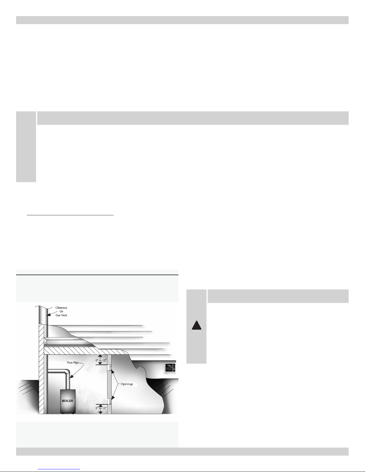
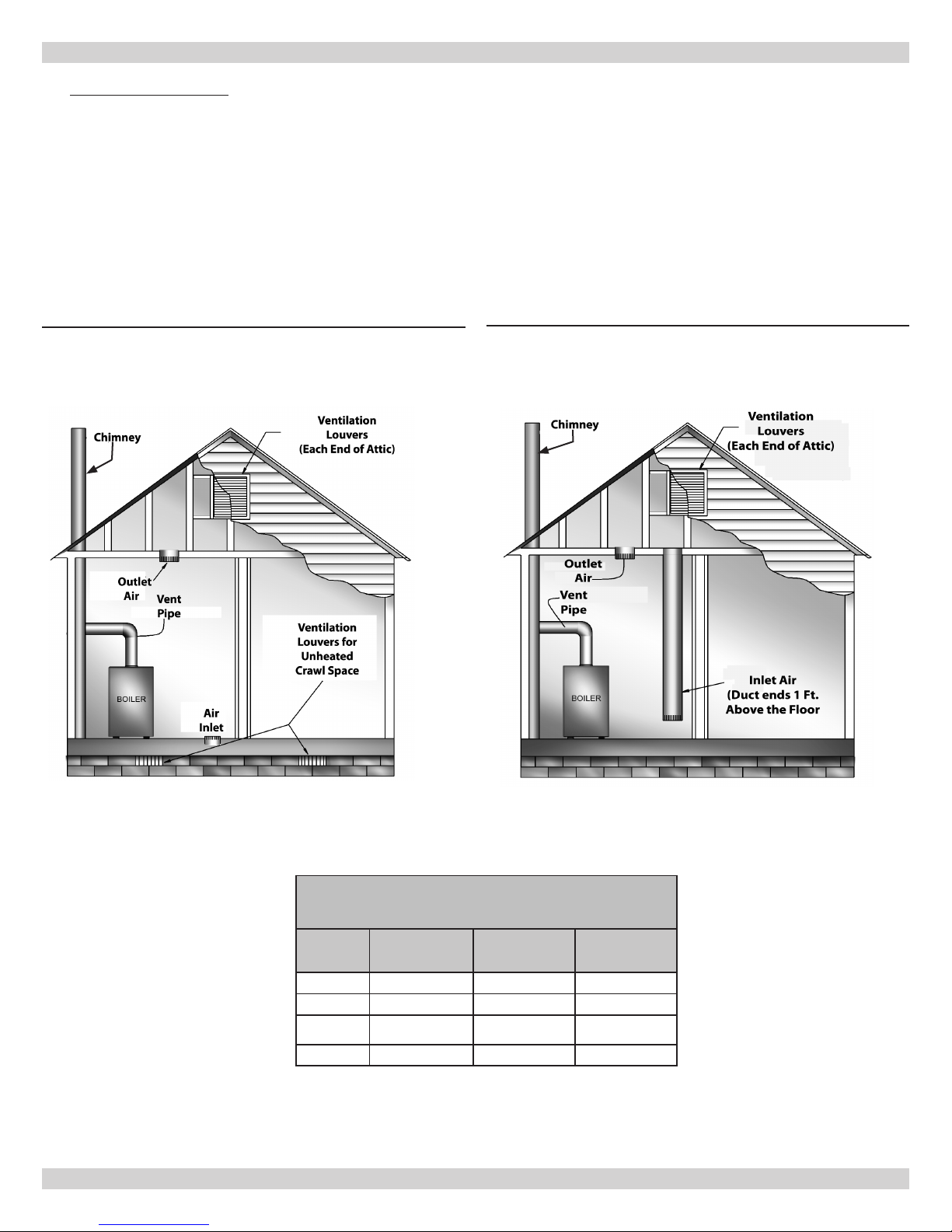
EXAMPLE 2: Boiler Located in Conned Space
All Air from Inside the Building:1.
an additional room(s) of sucient volume so that the combined volume of all spaces meets the criteria for an unconned space. e
total input of all gas utilization equipment installed in the combined space shall be considered in making this determination. Each opening shall have a minimum free area of one square inch per 1,000 Btu per hour of the total input rating of all gas utilization equipment in
the conned space, but not less that 100 square inches. One opening shall be within 12 inches of the top and one within 12 inches of the
bottom of the enclosure. e minimum dimension of air openings shall not be less than 3 inches (see
Figure 1 - Boiler Located in Conned Space
e conned space shall be provided with two permanent openings communicating directly with
Figure 1
WARNING
Be sure to provide enough fresh air for combustion.
Enough air insures proper combustion and assures that no
hazard will develop due to lack of oxygen.
!
If you use a replace or a kitchen or bathroom exhaust
fan, you should install an outside air intake. Otherwise
exhaust fans will rob the boiler and water heater of combustion air.
).
7
COMBUSTION AND VENTILATION AIR
All Air from Outdoors:2.
e conned space shall communicate with the outdoors in accordance with methods A or B. e minimum
dimension of air openings shall not be less than 3 in. Where ducts are used, they shall be of the same cross-sectional area as the free area
of the openings to which they connect.
Two permanent openings, one commencing within 12 inches of the top, and one commencing within 12 inches of the bottom, of A.
the enclosure shall be provided. e openings shall communicate directly, or by the ducts, with the outdoors or spaces (crawl or
attic) that freely communicate with the outdoors.
Where directly communicating with the outdoorsI.
ducts
(see Figure 3)
, each opening shall have a minimum free area of 1 sq. in, per 4000 Btu per hour of total input rating of all
(see Figure 2)
or where communicating to the outdoors through vertical
equipment in the enclosure.
Figure 2 - Directly Communicating to the Outdoors
Figure 3 - Vertical Ducts Communicating to the Outdoors
FRESH AIR DUCT CAPACITIES (1 Square inch per 4,000 Btuh)
Fresh Air
Duct Size
3” x 12” 144,000 108,000 36,000
8” x 8” 256,000 192,000 64,000
8” x 12” 384,000 288,000 96,000
8 ½” x 16” 512,000 384,000 128,000
see Figures - 2 and 3
100% Free Area
1/4” Wire Mesh
Table 3
75% Free Area
Metal Louvers
8
25% Free Area
Wood Louvers
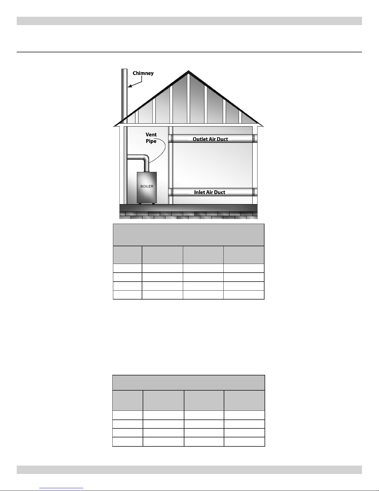
COMBUSTION AND VENTILATION AIR
Where communicating with the outdoors through horizontal ducts (see II.
of 1 area of sq. in. per 2000 Btu per hour of total rating of all equipment in the enclosure.
Figure 4 - Horizontal Ducts Communicating to the Outdoors
Figure 4
), each opening shall have a minimum free area
Table 4
FRESH AIR DUCT CAPACITIES (1 Square inch per 2,000 Btuh)
see Figure 3D
Fresh Air
Duct Size
3” x 12” 72,000 54,000 18,000
8” x 8” 128,000 96,000 32,000
8” x 12” 192,000 144,000 48,000
8 ½” x 16” 256,000 192,000 64,000
100% Free Area
1/4” Wire Mesh
75% Free Area
Metal Louvers
25% Free Area
Wood Louvers
One permanent opening commencing within 12 inches of the top of the enclosure shall be permitted where the equipment has B.
clearance of at least 1 inch from the sides and back and 6 inches from the front of the appliance. e opening shall directly communicate with the outdoors or shall communicate through a vertical or horizontal duct to the outdoors or to a crawl space or attic that
freely communicate with the out doors, and shall have a minimum free area of:
1 sq. inch per 3000 Btu per hour of the total input of all equipment located in the enclosure (see chart below).I.
Not less than the sum of the areas of all vent connectors in the conned space.II.
Table 5
FRESH AIR DUCT CAPACITIES (1 Square inch per 3,000 Btuh)
Fresh Air
Duct Size
100% Free Area
1/4” Wire Mesh
75% Free Area
Metal Louvers
25% Free Area
Wood Louvers
3” x 12” 108,000 81,000 27,000
8” x 8” 192,000 144,000 48,000
8” x 12” 288,000 216,000 72,000
8 ½” x 16” 384,000 288,000 96,000
9
SYSTEM PIPING
Place boiler in the selected location (as near chimney as pos-
1.
sible.) Your boiler is shipped assembled. You need only to install
the Relief Valve and a drain line to carry any water or steam to a
drain.
Install Relief Valve into the ¾” pipe on the top of the boiler.
2. See
Figure 5
the water or steam to a nearby drain. Do not connect directly to
a drain but leave an air gap. No shuto of any description shall
be placed between the safety relief valve and the boiler, or on
discharge pipes between such safety valves and the atmosphere.
Installation of the safety relief valve shall conform to the requirements of the ANSI/ASME Boiler and Pressure Vessel Code, Section IV. e manufacturer is not responsible for any water damage. Install Drain Valve in lower le side of boiler as marked.
Connect Supply and Return Lines to boiler. e connections
3.
may require certain additional ttings and parts, see
and 6)
is boiler is equipped with 1¼” supply and return connections
4.
on the right side of the boiler.
. Use ¾” Pipe and an elbow (not furnished) to carry
(Figures 5
.
Follow the mixing valve manufacturer’s installation instructions.
e minimum design return water temperature to the boiler to
4.
prevent condensation in the boiler and venting is 120ºF. e
minimum high limit setting is 140º F.
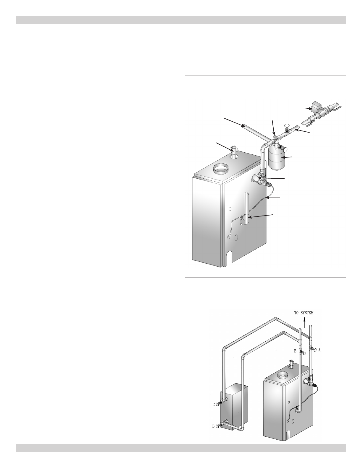
Figure 5 -Typical Hot Water Piping
Circulator
Cool Water Inlet
Relief Valve
Air Vent
Supply Main
Filtrol
Gauge
In connecting the cold water supply to the water inlet valve, make sure
that a clean water supply is available. When the water supply is from a
well or pump, a sand strainer should be installed at the pump.
A hot water boiler installed above radiation level must be equipped
with a low water cuto device. A periodic inspection is necessary, as
is ushing of oat type devices, per manufactures specic instruction.
Refer to local codes for low water cut-o requirements.
For Use With Cooling Units
is boiler, when used in connection with chilled water systems,
1.
must be installed so that the chilled water is piped parallel with
the heating boiler. Appropriate valves must be used to prevent
the chilled water from entering the heating boiler
When this boiler is connected to heating coils located in air
2.
(Figure 6)
.
handling units where they may be exposed to refrigerated air
circulation, the piping system shall be equipped with ow control
valves or other automatic means to prevent gravity circulation of
the boiler water during the cooling cycle.
Low Design Water Temperature Systems (Below 140º)
If the boiler is to be used in a heating system where water tem-
3.
peratures below 140ºF are desired (e.g. radiant oor heating) a
3-way or 4-way mixing valve or suitable alternative is required to
prevent low temperature return water from entering the boiler.
Sensor Wire
Return Line
Figure 6 - Chilled Water Piping
Valves A & B - Open For Heating; Closed For Cooling
Valves C & D -Closed For Heating; Open For Cooling
10
 Loading...