

Page 1
INSTALLATION INSTRUCTIONS
These instructions must be affixed on or adjacent to the boiler
MODEL PVWB
Continuous Pilot
PLPL
PL
PLPL
YMOUTHYMOUTH
YMOUTH
YMOUTHYMOUTH
WW
W
WW
AA
TERTER
A
TER
AA
TERTER
SERIES 2
Gas-FirGas-Fir
Gas-Fir
Gas-FirGas-Fir
Hot-WHot-W
Hot-W
Hot-WHot-W
BoilerBoiler
Boiler
BoilerBoiler
These Gas-Fired Water Boilers are low pressure, sectional
cast iron boilers Designed Certified by C.S.A. (Canadian
Standards Association) for use with Natural and Propane
Gases. They are constructed and hydrostatically tested for a
maximum working pressure of 50 psi (pounds per square
inch) in accordance with A.S.M.E. (American Society of
Mechanical Engineers) Boiler and Pressure Vessel Code
Section IV Standards for cast iron heating boilers.
aa
terter
a
ter
aa
terter
eded
ed
eded
ss
s
ss
MODEL PWB
Electronic
Intermittent Ignition
Warning: Improper installation, adjustment, alteration, service or maintenance can cause injury or
property damage. Refer to this manual. For assistance or additional information consult a qualified
installer, service agency or the gas supplier
DUNKIRK BOILERS
DUNKIRK, NEW YORK 14084 • AREA CODE 716 366-5500
MEMBER: The Hydronics Institute
1
Page 2
V
r
V
r
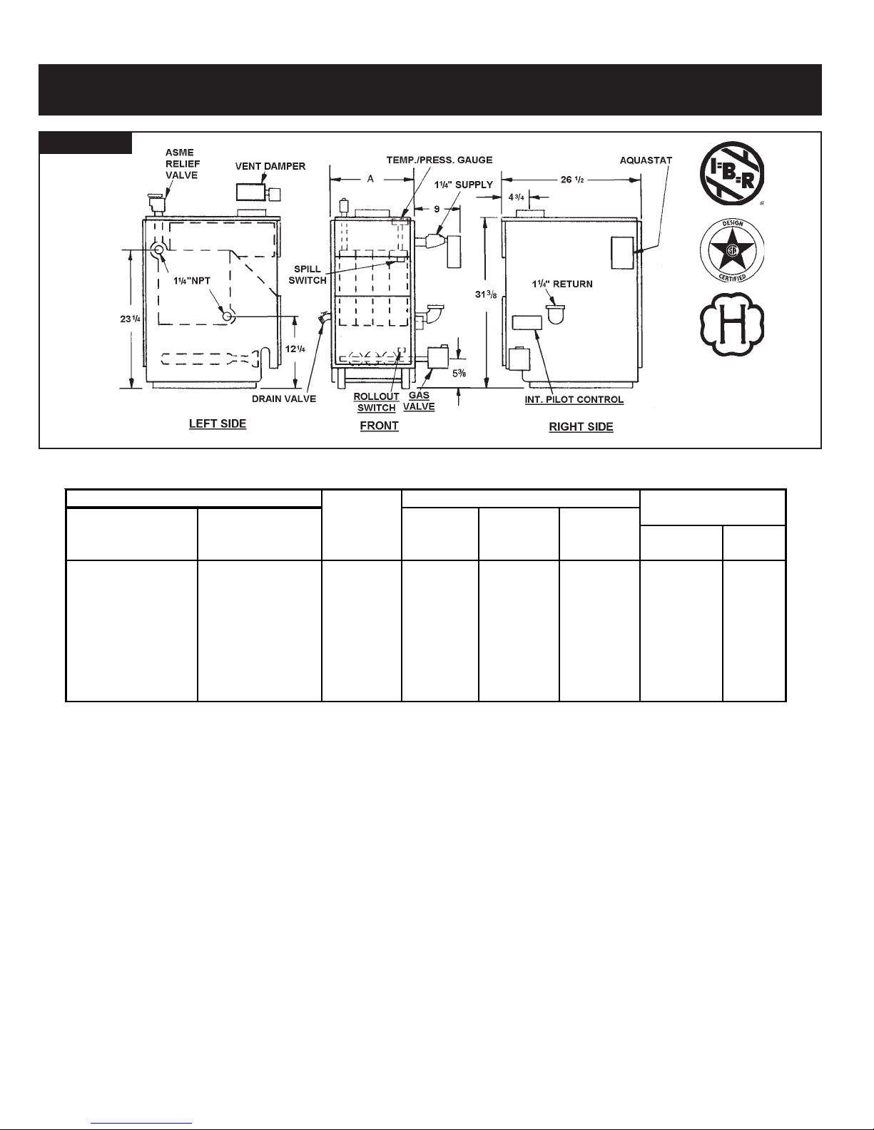
FIG. 1
Boiler Ratings and Capacities
GAS-FIRED HOT WATER BOILERS
BASIC BOILER UNIT NO. DIMENSIONS
Electronic Ignition Continuous Pilot NO. OF AGA/CGAHEATING NET I=B=R
With With SECTIONS INPUT CAPACITY RATING FLUE "A"
ent Dampe
PWB-2D PVWB-2D 2 37.5 30 26 4‡ 8
PWB-3D PVWB-3D 3 70 57 50 5 11¼
PWB-4D PVWB-4D 4 105 85 74 6 14½
PWB-5D PVWB-5D 5 140 113 98 6 17¾
PWB-6D PVWB-6D 6 175 142 123 7 21
PWB-7D PVWB-7D 7 210 170 148 7 24¼
PWB-8D PVWB-8D 8 245 198 172 7 27½
PWB-9D PVWB-9D 9 280 226 197 7 30¾
* MBH = 1,000 Btuh = British Thermal Unit Per Hour
Boilers are equipped for altitudes up to 2,000 feet only
U.S.A. Only - For altitudes above 2,000 feet, ratings should be reduced at the rate of 4% for each 1,000 feet above sea level.
Canada Only - Boilers may be used at high altitude by using a certified field conversion kit, resulting in a 10% derate.
+ Heating Capacity based on D.O.E. (Department of Energy) test procedure. Add 5½” to height when vent damper is used.
‡ 2 section boilers are equipped with a 3” diameter flue collar on the draft diverter, and use a furnished 3” x 4” increaser fitting to install
the furnished 4” vent damper.
ent Dampe
New York City MEA Number 39-86-E Vol. IV.
The Ratings marked “Net 1=B=R Ratings” indicate the amount
of remaining heat input that can be used to heat the radiation
or terminal units. The Net 1=B=R Ratings shown are based on
an allowance of 1.15 in accordance with the factors shown on
the 1=B=R Standard as published by The Hydronics Institute.
Selection of boiler size should be based upon “Net 1=B=R
Rating” being equal to or greater than the calculated heat loss
of the building.
The manufacturer should be consulted before selecting a boiler
for installations having unusual piping and pickup requirements.
These boilers must stand on a non-combustible floor. If in
NATURAL AND PROPANE GAS
(Inches)
*MBH *MBH *MBH DIAMETER WIDTH
stalled on a combustible floor, use Combustible Floor Base
Number 42135-1 or 146-14-031 (2-6 section boilers) or
42135-2 or 146-14-032 (7-9 section boilers).
BOILERS FOR USE AT HIGH ALTITUDE
This boiler is factory equipped for use at altitudes of 0-2,000
feet above sea level. For use at altitudes above 2,000 feet
above sea level, the input ratings are reduced by a change in
main burner orifice size.
U.S.A. Only - For altitudes above 2,000 feet above sea
level, input ratings should be reduced at the rate of 4% for
each 1,000 feet above sea level. Consult the National Fuel
2
Page 3

Before You Start
Gas Code (NFPA54/ANSI Z223.1-latest edition), or the
manufacturer for correct orifice sizing information. High
altitude orifices are available from the boiler manufacturer.
Canada Only - For altitudes in the range of 2,000-4,500
feet above sea level, boilers may be field equipped for use
at high altitude by using a certified field conversion kit. The
change in main burner orifice size results in the boiler’s
input rating being reduced by 10%. The conversion shall
be carried out by a manufacturer’s authorized
representative, in accordance with the requirements of the
manufacturer, provincial or territorial authorities having
jurisdiction and in accordance with the requirements of the
CSA-B149.1 and CSA-B149.2 Installation Codes. The
certified field conversion kit includes a conversion data
plate, which must be attached to the boiler adjacent to the
rating plate, indicating that the boiler has been converted
for high altitude use. The conversion data plate must be
filled in with the correct conversion information.
Check to be sure you have the right size boiler before starting
the installation. _ See rating and capacity table on previous
page. Also be sure the new boiler is or the type of gas you are
using. Check the rating plate on the right side of the boiler.
You must see that the boiler is supplied with the correct type
of gas, fresh air for combustion, and a suitable electrical supply.
Also, the boiler must be connected to a suitable venting system
and an adequate piping system. Finally, a thermostat, properly
located, is needed for control of the heating system. If you
have any doubts as to the various requirements, check with
local authorities and obtain professional help where needed.
Take the time to complete all of the steps for SAFE and
PROPER operation of the heating system.
If this boiler is installed in a building under construction,
special care must be taken to insure a clean combustion
air supply during the construction process. Airborne
particulates such as from drywall dust and from fiberglass
insulation can clog the burner ports and cause incomplete
combustion and sooting.
Where required by the authority having jurisdiction, the
installation must conform to American Society of Mechanical
Engineers Safety Code for Controls and Safety Devices for
Automatically Fired Boilers, No. CSD-1.
The installation must conform to the requirements of the
authority having jurisdiction or, in the absence of such
requirements, to the National Fuel Gas Code, ANSI Z223.1latest revision.
In Canada, the boiler shall be installed according to CSA-
13149.1 and .2, Installation Code for Gas Burning
Appliances and Equipment.
Installers - Follow local regulations with respect to
installation of CO detectors. Follow maintenance
recommendations in this instruction manual.
Techniciens - Veuillez vous conformer a la
réglementation en vigueur concernant I’ installation des
détecteurs d’oxyde de carbone. Suivre les consignes
d’entretien figurant dans le manuel dínstruction ci-joint.
KEEP BOILER AREA CLEAN AND FREE FROM COMBUSTIBLE MATERIALS,
GASOLINE AND OTHER FLAMMABLE VAPORS AND LIQUIDS
3
Page 4
Locating the Boiler
r
r
V
V
1. Select level location as centralized with piping system, and
as near chimney, as possible.
2. Place crated boiler at selected location, remove crate
by pulling crate sides from top and bottom boards.
Combustible floors: When boiler is to be installed on a
combustible floor, a Special Base Plate must be used 146-14-031 (2-6 Section) or 146-14-032 (7-9 Section).
This boiler must not be installed on carpeting.
3. Boiler is to be level. Metal shims may be used under
base legs for final leveling.
4. Additional clearances for service may exceed clearances
for fire protection. Always comply with the minimum fire
protection clearances shown on the boiler. An 18 inch
clearance should be maintained on any side where
passage is required to access another side for cleaning,
servicing, inspection or replacement of any part that may
need attention. An 18-inch clearance is recommended
on the control side for servicing.
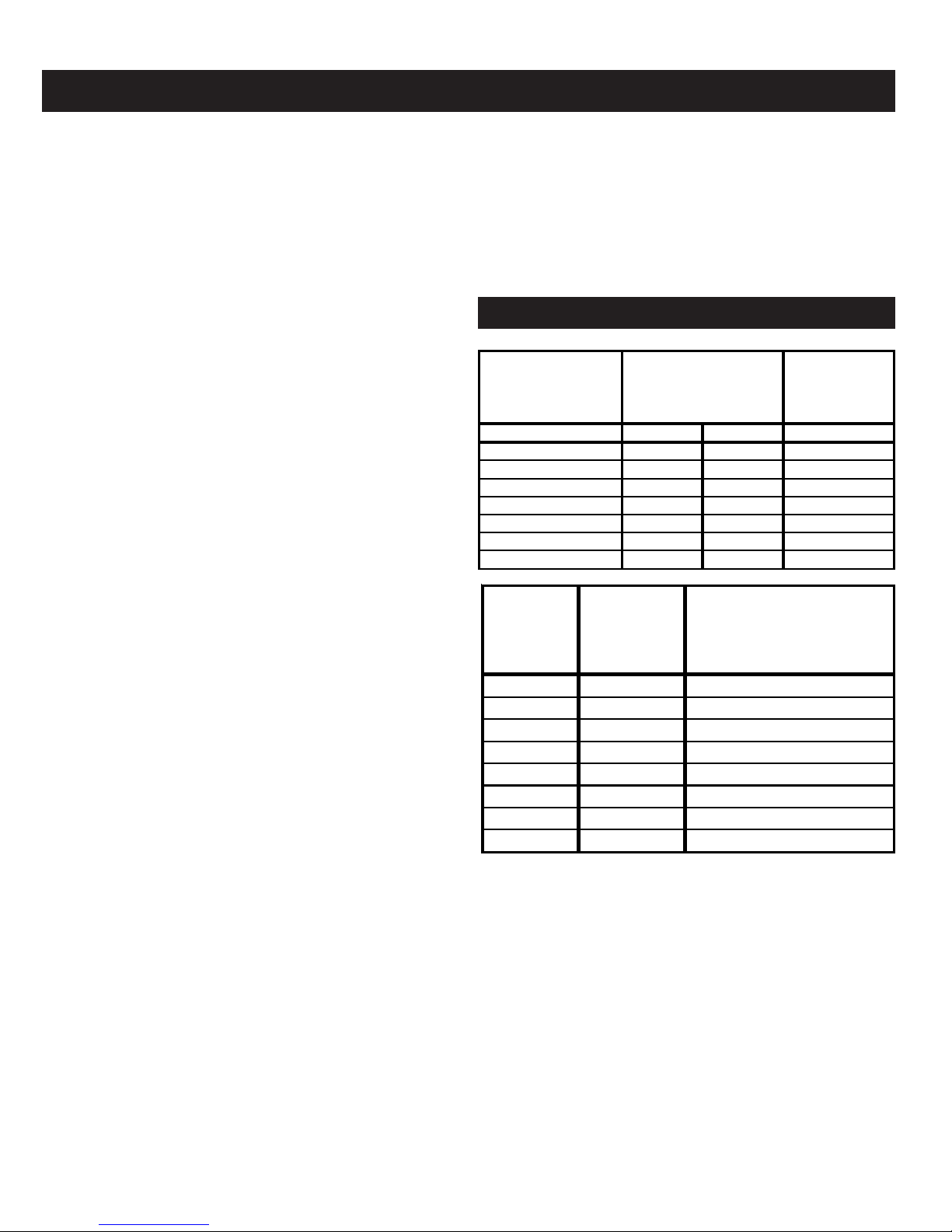
Figure 2 shows minimum clearances to combustible
construction. Rooms that are large in comparison with
the size of the boiler are defined as rooms having a
volume equal to or greater than 16 times the volume of
the boiler. Where the actual ceiling height of a room is
greater that 8', the volume of a room shall be figured on
the basis of a ceiling height of 8'. Determination of room
size should be based do the total volume of all gas fired
equipment installed in the room. Consult section 6.3.1
of the National Fuel Gas Code for further information,
including approved methods for reducing clearances in
large rooms.
5. Equipment shall be installed in a location in which the
facilities for ventilation permit satisfactory combustion
of gas, proper venting, and maintenance of ambient
temperature at safe limits under normal conditions of use.
Equipment shall be located so as not to interfere with
proper circulation of air. When normal infiltration does
not provide the necessary air, outside air shall be
introduced (See Page 4 - “Fresh Air for Combustion”).
6. Advise owner to keep air passages free of obstructions.
Ventilating and combustion air must enter boiler room
without restrictions.
7. The boiler shall be installed such that the automatic gas
ignition system components are protected from water
(dripping, spraying, rain, etc.) during appliance operation
and service (condensate trap, control replacement, etc.).
FIG. 2 - MINIMUM CLEARANCE DIMENSIONS
Alcove, or Room Not
Large in Comparison
With Boiler
2-5 SECT. 6-9 SECT. 2-9 SECT.
Top 6" 6" 6"
Rear 6" 6" 6"
Control Side 8" 24" 6"
Opposite Side 6" 24" 6"
Front 18" 18" 18"
Flue/Vent Connector 6" 6" 6"
Near Boiler Piping 1" 1" 1"
Room Large In
Comparison
With Boiler
Minimum Room
Boile
Size
Boile
olume Required
olume To Be Large
(Cu. Ft.) Room (Cu. Ft)*
2 sect. 3.8 61.6
3 sect. 5.4 86.6
4 sect. 7.0 111.6
5 sect. 8.5 136.6
6 sect. 10.1 161.7
7 sect. 11.7 186.7
8 sect. 13.2 211.7
9 sect. 14.8 236.7
* FOR ROOM WITH SINGLE BOILER ONLY THIS UNIT MUST
BE SET ON A CONCRETE OR OTHER NON-COMBUSTIBLE
MATERIAL BASE OR FLOOR.
4
Page 5
Fresh Air for Combustion
Provision for combustion and ventilation air must be in accordance with Section 5.3, Air for Combustion and Ventilation,
of the National Fuel Gas Code, ANSI Z223.1-latest revision, or applicable provisions of the local building codes.
WARNING
Be sure to provide enough fresh air for combustion. Enough
air insures proper combustion and assures that no hazard
will develop due to the lack of oxygen.
Y ou must provide for enough fresh air to assure proper combustion. The
fire in the boiler uses oxygen. It must have a continuous supply . The air in
a house contains only enough oxygen to supply the burner for a short
time. Outside air must enter the house to replace that used by the burner.
Study following examples 1 and 2 to determine your fresh air requirements .
EXAMPLE 1: Boiler Located in Unconfined Space
An unconfined space is defined as a space whose volume is not less
than 50 cubic feet per 1,000 Btu per hour of the total input rating of all
appliances installed in that space.
If your boiler is in an open area (unpartitioned basement) in a
conventional house, the air that leaks through the cracks around doors
and windows will usually be adequate to provide air for combustion.
The doors should not fit tightly. Do not caulk the cracks around the
windows.
Equipment located in buildings of unusually tight construction shall be
provided with air for combustion, ventilation, and dilution of flue gases
using the methods described in example 2B or shall be specially
engineered. The authority having jurisdiction must approve specially
engineered installations.
EXAMPLE 2: Boiler Located in Confined Space
A. All Air from Inside the Building: The confined space shall be
provided with two permanent openings communicating directly with
an additional room(s) of sufficient volume so that the combined
volume of all spaces meets the criteria for an unconfined space.
The total input of all gas utilization equipment installed in the
combined space shall be considered in making this determination.
Each opening shall have a minimum free area of one square inch
per 1,000 Btu per hour of the total input rating of all gas utilization
equipment in the confined space, but not less that 100 square
inches. One opening shall be within 12 inches of the top and one
within 12 inches of the bottom of the enclosure. The minimum
dimension of air openings shall not be less than 3 inches.
B. All Air from Outdoors: The confined space shall communicate
with the outdoors in accordance with methods 1 or 2. The minimum
dimension of air openings shall not be less than 3 in. Where ducts
are used, they shall be of the same cross-sectional area as the
free area of the openings to which they connect.
1. Two permanent openings, one commencing within 12 inches of
the top. and one commencing within 12 inches of the bottom,
of the enclosure shall be provided. The openings shall
communicate directly, or by the ducts, with the outdoors or
spaces (crawl or attic) that freely communicate with the outdoors.
a) Where directly communicating with the outdoors or where
communicating to the outdoors through vertical ducts. each
opening shall have a minimum free area of 1 sq. in. per 4000
Btu per hour of total input rating of all equipment in the enclosure.
(See Figure 3B)
b) Where communicating with the outdoors through horizontal ducts.
each opening shall have a minimum free area of 1 sq. in. per
2000 Btu per hour of total input rating of all equipment in the
enclosure. (See Figure 38.)
If you use a fireplace or a kitchen or bathroom exhaust fan,
you should install an outside air intake. These devices will
rob the boiler and water heater of combustion air.
2. One permanent opening commencing with 12 inches of
a) 1 sq. inch per 3000 Btu per hour of the tatal input of all
b) Not less than the sum of the areas of all vent connectors
5
NOTE
the top of the enclosure, shall be permitted where the
equipment has clearance of at least 1 inch from the sides
and back and 6 inches from the front of the appliance. The
opening shall directly communicate with the outdoors or
shall communicate through a vertical or horizontal duct to
the outdoors or spaces (crawl or attic) that freely
communicate with the outdoor, and shall have a minimun
free area of:
equipment located in the enclosure ( See Figure 4), and
in theconfined space.
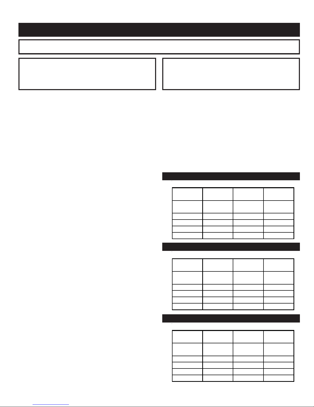
Figure 3A - FRESH AIR DUCT CAPACITIES (Btuh)
1 Square Inch per 4,000 Btuh
100% Free 75% Free 25% Free
Area Area Area
Fresh Air ¼" Wire Metal Wood
Duct Size Mesh Louvers Louvers
3" x 12" 144,000 108,000 36,000
8" x 8" 256,000 192,000 64,000
8" 12" 384,000 288,000 96,000
8½" x 16" 512,000 384,000 128,000
Figure 3B - FRESH AIR DUCT CAPACITIES (Btuh)
1 Square Inch per 2,000 Btuh
100% Free 75% Free 25% Free
Area Area Area
Fresh Air ¼" Wire Metal Wood
Duct Size Mesh Louvers Louvers
3" x 12" 72,000 54,000 18,000
8" x 8" 128,000 96,000 32,000
8" 12" 192,000 144,000 48,000
8½" x 16" 256,000 192,000 64,000
Figure 4 - FRESH AIR DUCT CAPACITIES (Btuh)
1 Square Inch per 3,000 Btuh
100% Free 75% Free 25% Free
Area Area Area
Fresh Air ¼" Wire Metal Wood
Duct Size Mesh Louvers Louvers
3" x 12" 108,000 81,000 27,000
8" x 8" 192,000 144,000 48,000
8" 12" 288,000 216,000 72,000
8½" x 16" 384,000 288,000 96,000
Page 6

Installation - System Piping
1. Place boiler in the selected location (as near chimney as
possible.) Your boiler is shipped assembled. You need only
to install the Relief Valve and a drain line to carry any water
or steam to a drain.
2. Install Relief Valve into the 3/4" pipe on the top of the boiler.
See Figure 5. Use 3/4” Pipe and an elbow (not furnished) to
carry the water or steam to a nearby drain. Do not connect
directly to a drain but leave an air gap. No shutoff of any
description shall be placed between the safety relief valve
and the boiler, or on discharge pipes between such safety
valves and the atmosphere. Installation of the safety relief
valve shall conform to the requirements of the ANSI/ASME
Boiler and Pressure Vessel Code, Section IV. The
manufacturer is not responsible for any water damage. Install
Drain Valve in lower left side of boiler as marked.
3. Connect Supply and Return Lines to boiler. The connections
may require certain additional fittings and parts, as shown
on diagram (Figs. 5 and 6).
4. This boiler is equipped with 1 1/4" supply and return
connections on both the left and right sides of the boiler.
In connecting the cold water supply to the water inlet valve,
make sure that a clean water supply is available. When the
water supply is from a well or pump, a sand strainer should be
installed at the pump.
A hot water boiler installed above radiation level must be
equipped with a low water cutoff device. A periodic inspection
is necessary, as is flushing of float type devices, per
manufacturers specific instruction.
The minimum design return water temperature to the boiler to
prevent condensation in the boiler and venting is 120° F. The
minimum high limit setting is 140° F.
CAUTION
THE ISOLATION BALL VALVES CONTAIN TEFLON
SEATS AND SEALS. OVERHEATING THIS VALVE MAY
CAUSE PREMATURE FAILURE.
FIG. 5 - TYPICAL HOT WATER PIPING
FOR USE WITH COOLING UNITS
A. This boiler, when used in connection with chilled water
systems, must be installed so that the chilled water is piped
in parallel with the heating boiler. Appropriate valves must
be used to prevent the chilled water from entering the heating
boiler (Fig. 6).
B. When this boiler is connected to heating coils located in air
handling units where they may be exposed to refrigerated
air circulation, the piping system shall be equipped with flow
control valves or other automatic means to prevent gravity
circulation of the boiler water during the cooling cycle.
LOW DESIGN WATER TEMPERATURE
SYSTEMS (BELOW 140°)
If the boiler is to be used in a heating system where design
water temperatures below 140° F are desired (e.g. radiant floor
heating), a 3-way or 4-way mixing valve or suitable alternative
is required to prevent low temperature return water from
entering the boiler. Follow the mixing valve manufacturer’s
installation instructions.
FIG. 6 - CHILLED WATER PIPING
6
Page 7
Chimney and Vent Pipe Connection
For boilers for connection to gas vents or chimneys, vent installations shall be in
accordance with Part 7, Venting of Equipment, of the National Fuel Gas Code, ANSI
Z223.1-latest revision and applicable provisions of the local building codes.
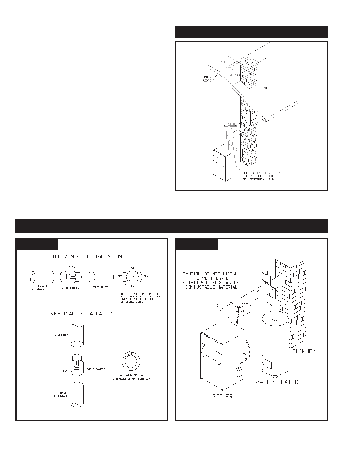
CHECK YOUR CHIMNEY
This is a very important part of your heating system. It must be
clean, the right size, properly constructed and in GOOD
CONDITION. No boiler can function properly with a bad
chimney. Fig. 7 gives typical chimney sizes. Fig. 8 gives you
an idea how a boiler might be vented to a chimney. Note that
the height (HT) is measured from the vent pipe to the top.
CHIMNEY SIZING
Chimney sizing, and all other aspects of the vent installation
must be in accordance with Part 7 of the National Fuel Gas
Code, ANSI Z223.1 latest revision, and applicable provisions
of the local building codes.
In Canada, follow CAN/CGA B149.1 and B149.2, Installation
Codes for Gas Burning Appliances and Equipment.
CONNECTING THE VENT DAMPER AND VENT
CONNECTOR
Refer to Fig. 1 flue diagram for the size and location of the vent
(flue opening). Use a 28 gauge (minimum) galvanized pipe to
connect to the chimney.
IMPORTANT - The damper blade on the furnished vent damper
has a 1/2 square inch hole (approximately3/4 diameter). On
boilers equipped with standing pilot, the hole must be left open.
On boilers equipped with intermittent ignition, the hole should
be plugged by using the plug supplied with the vent damper.
1. Position furnished vent damper on top of flue outlet collar.
Fasten damper securely to flue outlet collar with sheet
metal screws. Make sure damper blade has clearance to
operate inside of diverter.
On 2 section boilers equipped with vent damper, the
supplied 4-inch vent damper is equipped with a 3- to 4inch adapter so that the 4-inch vent damper may be
installed on the boiler’s 3-inch flue outlet collar. Fasten all
fittings securely.
As An Option (U.S.A. Only)
The damper may be installed in any horizontal or vertical
position, closer to the flue outlet collar preferred. Follow
the diagrams - Figures 9, 10 and 11.
2. Install the vent damper to service only the single boiler for
which it is intended. The damper position indicator shall
be in a visible location following installation. Locate the
damper so that it is accessible for servicing.
3. The damper must be in the open position when appliance
main burners are operating.
4. The boiler is equipped with a factory wired harness that
plugs into the vent damper.
5. Vent pipe must be same size as the flue outlet collar, except
2 section boilers with vent damper as noted above.
6. Slope pipe up from boiler to chimney not less than 1/4” per foot.
7. Run pipe as directly as possible with as few elbows as
possible.
8. Do not connect to fireplace flue.
9. End of vent pipe must be flush with inside face of chimney
flue. Use a sealed-in thimble for the chimney connection.
10. Horizontal run should not be longer than 3/4 the
chimney height (HT) (Fig, 8).
The sections of vent pipe should be fastened with sheet metal
screws to make the piping rigid. Horizontal portions of the vent
system must be supported to prevent sagging. Use stovepipe
wires every 5' to support the pipe from above If the vent pipe
must go through a crawl space, double wall vent pipe should
be used Where vent pipe passes through a combustible wall
or partition, use a ventilated metal thimble. The thimble should
be 4 inches larger in diameter than the vent pipe.
FIG. 7 - TYPICAL CHIMNEY SIZES
FLUE AREA IN INCHES
Boiler Input *HT. *HT. *HT.
Btuh 10-15 Ft. 10-25 Ft. 25 Ft. UP
Up to 100,000 6 x 6 6 x 5 5 x 5
Up to 155,000 6 x 7 6 x 6 6 x 5
Up to 230,000 7 x 8 7 x 7 6 x 7
Up to 350,000 9 x 9 8 x 9 8 x 8
* HT = top of thimble to top of flue. See Fig. 8
For boiler input refer to table, page 2.
For information only - not meant to imply minimum sizes.
MINIMUM VENT PIPE CLEARANCE
Wood and other combustible materials must not be closer than
6" from any surface of single wall metal vent pipe. Listed Type
B vent pipe or other listed venting systems shall be installed in
accordance with their listing.
REMOVING EXISTING BOILER FROM
COMMON VENTING SYSTEM
When an existing boiler is removed from a common venting
system, the common venting system is likely to be too large
for proper venting of the appliances remaining connected to it.
At the time of removal of an existing boiler, the following steps
shall be followed with each appliance remaining connected to
the common venting system placed in operation, while the other
appliances remaining connected to the common venting system
are not in operation.
1. Seal any unused openings in the common venting system.
2. Visually inspect the venting system for proper size and
horizontal pitch and determine there is no blockage or
restriction, leakage, corrosion and other deficiencies which
could cause an unsafe condition.
7
Page 8
3. Insofar as is practical, close all building doors and windows
and all doors between the space in which the appliances
remaining connected to the common venting system are
located and other spaces of the building. Turn on clothes
dryers and any appliance not connected to the common
venting system. Turn on any exhaust fans, such as range
hoods and bathroom exhausts, so they will operate at
maximum speed. Do not operate a summer exhaust fan.
Close fireplace dampers.
4. Place in operation the appliance being inspected. Follow
the lighting instructions. Adjust thermostat so appliance
will operate continuously.
5. Test for spillage at the draft hood relief opening after 5
minutes of main burner operation. Use the flame of a match
or candle, or smoke from a cigarette, cigar or pipe.
6. After it has been determined that each appliance remaining connected to the common venting system properly
vents when tested as outlined above, return doorswindows,
exhaust fans, fireplace dampers and any other gas-burning
appliance to their previous conditions of use.
7. Any improper operation of the common venting system
should be corrected so the installation conforms with the
National Fuel Gas Code, ANSI Z223.1-latest revision.
When resizing any portion of the common venting system,
the common venting system should be resized to approach
the minimum size as determined using the appropriate
tables in Part 11 in the National Fuel Gas Code, ANSI
Z223.1-latest revision.
FIG. 8 TYPICAL MASONRY CHIMNEY REQUIREMENTS
Vent connectors serving appliances vented by natural draft
shall not be connected into any portion of mechanical draft
systems operating under positive pressure.
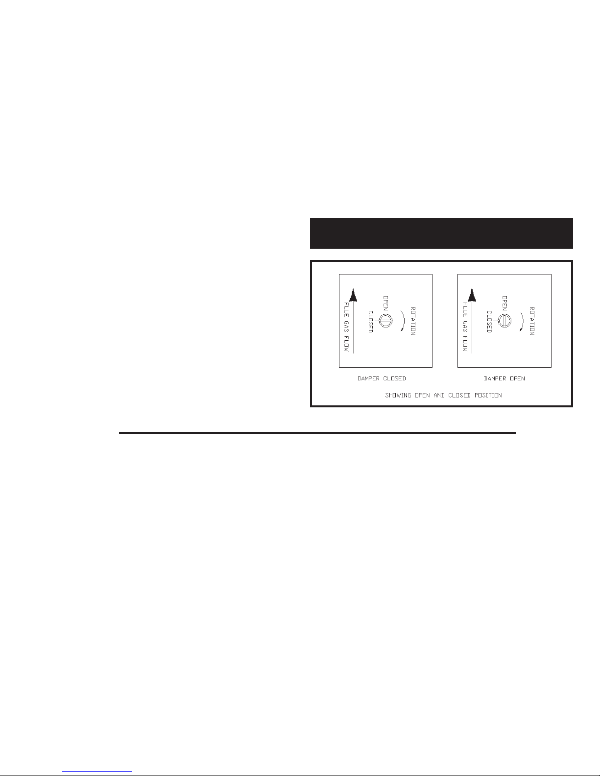
FIG. 9
Vent Damper Operation
FIG. 10
8
Page 9
TYPICAL INSTALLATION FOR VENT DAMPER
NOT CAUTION AND FOOTNOTES
1. I nstall the vent damper to service only the single
appliance for which it is intended. If improperly
installed, a hazardous condition, such as an explosion
or carbon monoxide poisoning, could result.
2. Do not install the vent damper on pipe curve.
3. Do not run wires near high temperature surfaces. Use
stand-off brackets if necessary.
For safe, efficient operation, the vent damper and all flue product
carrying areas of the appliance must be checked annually by
you, with particular attention given to deterioration from
corrosion or other sources. If you see corrosion or other
deterioration, contact your heating contractor for repairs. Check
vent damper operation as follows:
1. When the boiler is off, check that the vent damper positions
indicator points to the closed position, Fig. 1 1.
2. Turn the thermostat or controller up to call for heat and
check the vent damper indicator points to the open
position, Fig. 11.
3. Turn the thermostat or controller down again and check
that the damper position indicator returns to the closed
position.
located on the damper controller. The thermostat will control
the burner firing as before, while the damper will remain open.
DO NOT turn damper open manually or motor damage will
result. Set switch to “AUTOMATIC OPERATION” to close vent
damper during burner off cycle.
For further information, and for a vent damper troubleshooting
guide, refer to the manual that was packaged with the vent
damper.
The vent damper must be inspected at least once a year
by a trained, experienced service technician. The name of
the person who originally installed your vent damper is
shown on the installation label.
FIG. 11
VENT DAMPER POSITION INDICATOR
MANUAL OPERATION OF THE VENT DAMPER
The vent damper may be placed in the open position to permit
burner operation by using the “HOLD DAMPER OPEN” switch,
NOTES FOR CANADA ONLY
1. Canadian Standard CAN1-2.28-M81 prohibits the use of
vent dampers on propane fired appliances equipped with
intermittent ignition.
2. In Canada, the vent damper must be attached directly to
the flue outlet collar, with the exception of the 2 section
boiler, where the 3- to 4-inch adapter is supplied with the
vent damper.
No other interconnectng pieces are allowed between the
boiler and the vent damper.
3. In Canada, vent dampers are not an option. Boilers are
either factory built for use with a vent damper and the vent
damper is supplied with the boiler, or they are factory built
for use without a vent damper. In the second case a vent
damper cannot be installed later.
9
Page 10
Gas Supply Piping
CHECK GAS SUPPLY
The gas pipe to your boiler must be the correct size for the
length of the run and for the total Btu per hour input of all gas
utilization equipment connected to it. See Fig. 12 for the proper
size. Be sure your gas line complies with local codes and gas
company requirements.
The boiler and its individual shutoff valve must be disconnected
from the gas supply piping system during any pressure testing
of that system at test pressures in excess of 1/2 psig (3.5 kPa).
The boiler must be isolated from the gas supply piping system
by closing its individual manual shutoff valve during any pressure testing of the gas supply piping system at test pressures
equal to or less than 1/2 psig (3.5 kPa).
CONNECTING THE GAS PIPING
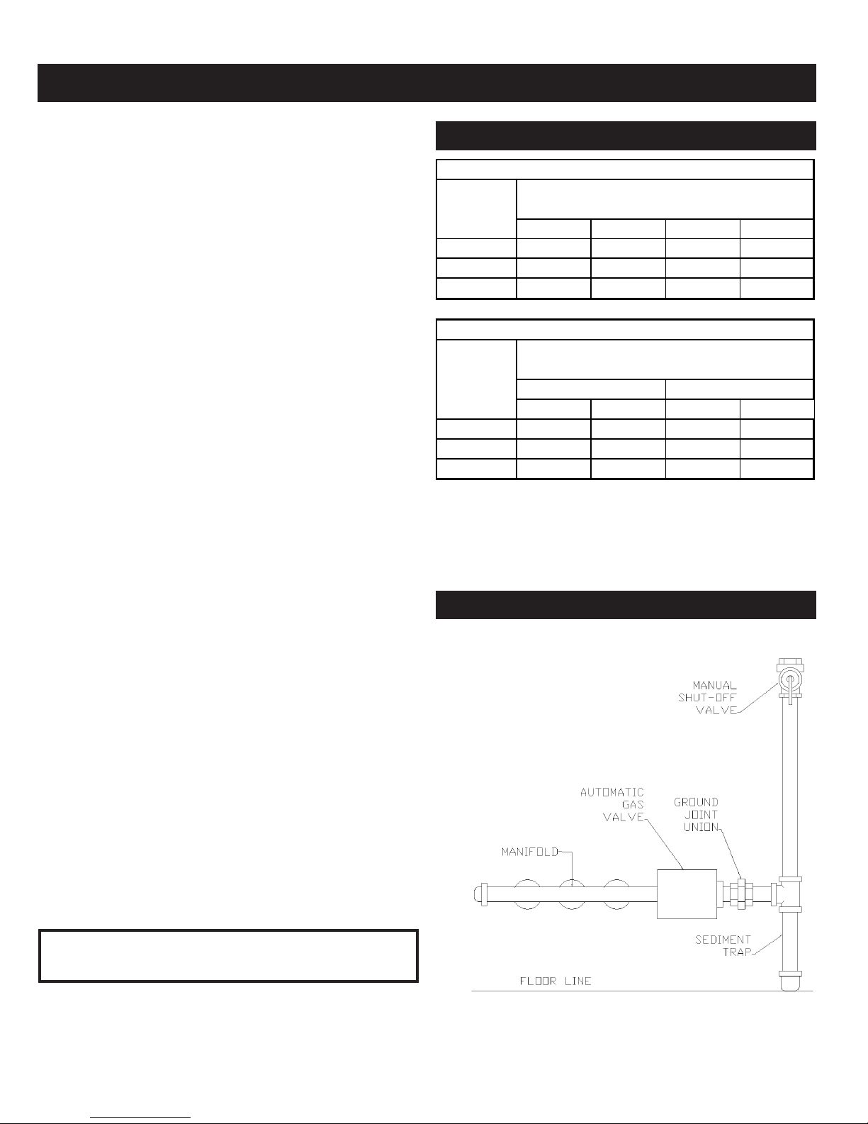
Refer to Fig. 13 for the general layout at the boiler. It shows
the basic fittings you will need. The gas line enters the boiler
from the right side.
The following rules apply:
1. Use only those piping materials and joining methods listed
as acceptable by the authority having jurisdiction, or in
the absence of such requirements, by the National Fuel
Gas Code, ANSI 223.1-latest revision. In Canada, follow
the CAN/CGA B149.1 and .2 Installation Codes for Gas
Burning Appliances and Equipment.
2. Use pipe joint compound suitable for LP gas on male
threads only.
3. Use ground joint unions.
4. Install a sediment trap upstream of gas controls.
5. Use two pipe wrenches when making the connection to
the gas valve to keep it from turning.
6. Install a manual shut-off valve in vertical pipe about 5
feet above floor.
7. Tighten all joints securely.
8. Propane gas connections should only be made by a
licensed propane installer.
9. Two-stage regulation should be used by the propane
installer.
10. Propane gas piping should be checked out by the
propane installer.
FIG. 12 - GAS PIPE SIZES
NATURAL GAS
Pipe Capacity - Btu Per Hour Input
Le ngth of
Pipe - Ft.
20
40
60
1/2" 3/4" 1" 1¼"
92,000 190,000 350,000 625,000
63,000 130,000 245,000 445,000
50,000 105,000 195,000 365,000
Includes Fittings
PROP ANE GAS
Pipe Capacity - Btu Per Hour Input
Le ngth of
Pipe - Ft.
20
40
60
* Outside diameter
The lenght of pipe or tubing should be measured from the gas
meter or propane second stage regulator.
Copper Tubing* Iron Pipe
5/8" 3/4" 1/2" 3/4"
131,000 216,000 189,000 393,000
90,000 145,000 129,000 267,000
72,000 121,000 103,000 217,000
Includes Fittings
FIG. 13 - GAS PIPE SIZES
CHECKING THE GAS PIPING
Upon completion of piping, check immediately for gas leaks.
Open the manual shut-off valve. Test for leaks by applying soap
suds (or a liquid detergent) to each joint. Bubbles forming indicate
a leak. CORRECT EVEN THE SMALLEST LEAK AT ONCE.
WARNING
Never use a match or open flame to test for leaks.
10
Page 11

Electrical Wiring
All electrical work must conform to local codes as well as the
National Electrical Code, ANSI/NFPA-70, latest revision. In
Canada, electrical wiring shall comply with the Canadian Elec-
trical Codes, CSA-C22.1 and.2.
ELECTRIC POWER SUPPLY
Run a separate 120 Volt circuit from a separate overcurrent
protective device in the electrical service entrance panel.
This should be a 15 ampere circuit. Locate a shut-off switch
at the boiler. It must be turned off during any maintenance.
Connect 120 Volt power supply to aquastat terminals L1
(HOT) and L2.
The boiler, when installed, must be electrically grounded in
accordance with the requirements of the authority having jurisdiction or, in the absence of such requirements, with the
National Electrical Code, ANSI/NFPA No. 70-latest revision.
Run a 14 gauge or heavier copper wire from the boiler to a
grounded connection in the service panel or a properly driven
and electrically grounded ground rod.
WARNING
Turn off electric power at fuse box before making any line
voltage connections. Follow local electrical codes.
INSTALL YOUR THERMOSTAT
The thermostat location has an important effect on the operation
of your boiler system. BE SURE TO FOLLOW THE
INSTRUCTIONS INCLUDED WITH YOUR THERMOSTAT.
a vertically mounted outlet box. It should be sensing average
room temperature, so avoid the following:
DEAD SPOTS:
Behind doors
Corners and alcoves
HOT SPOTS:
Concealed pipes
Fireplace
TV sets
Radios
Lamps
Direct sunlight
Kitchens
COLD SPOTS:
Concealed pipes or ducts
Stairwells - drafts
Doors – drafts
Unheated rooms on other side of wall
Set heat anticipator at .2 amps. 24 Volt thermostat connects
to aquastat terminals T and TV.
VENT DAMPER WIRING
The boiler is equipped with a factory wired harness with 4 pin
molex plug, that plugs into a 4 pin molex receptacle inside the
vent damper operator.
The vent damper must be connected for the boiler to
operate.
Wiring diagrams follow for the various different models.
Locate the thermostat about five feet above the floor on an
inside wall. It may be mounted directly on the wall or on
CAUTION
Label all wires prior to disconnection when servicing
controls. Wiring errors can cause improper and dangerous
operation. Verify proper operation after servicing.
The pump does not come pre-installed on the boiler. It must
be connected to the circulator harness in the field according to
the pump manufacturer’s instructions and the wiring diagrams
in this manual.
11
Page 12
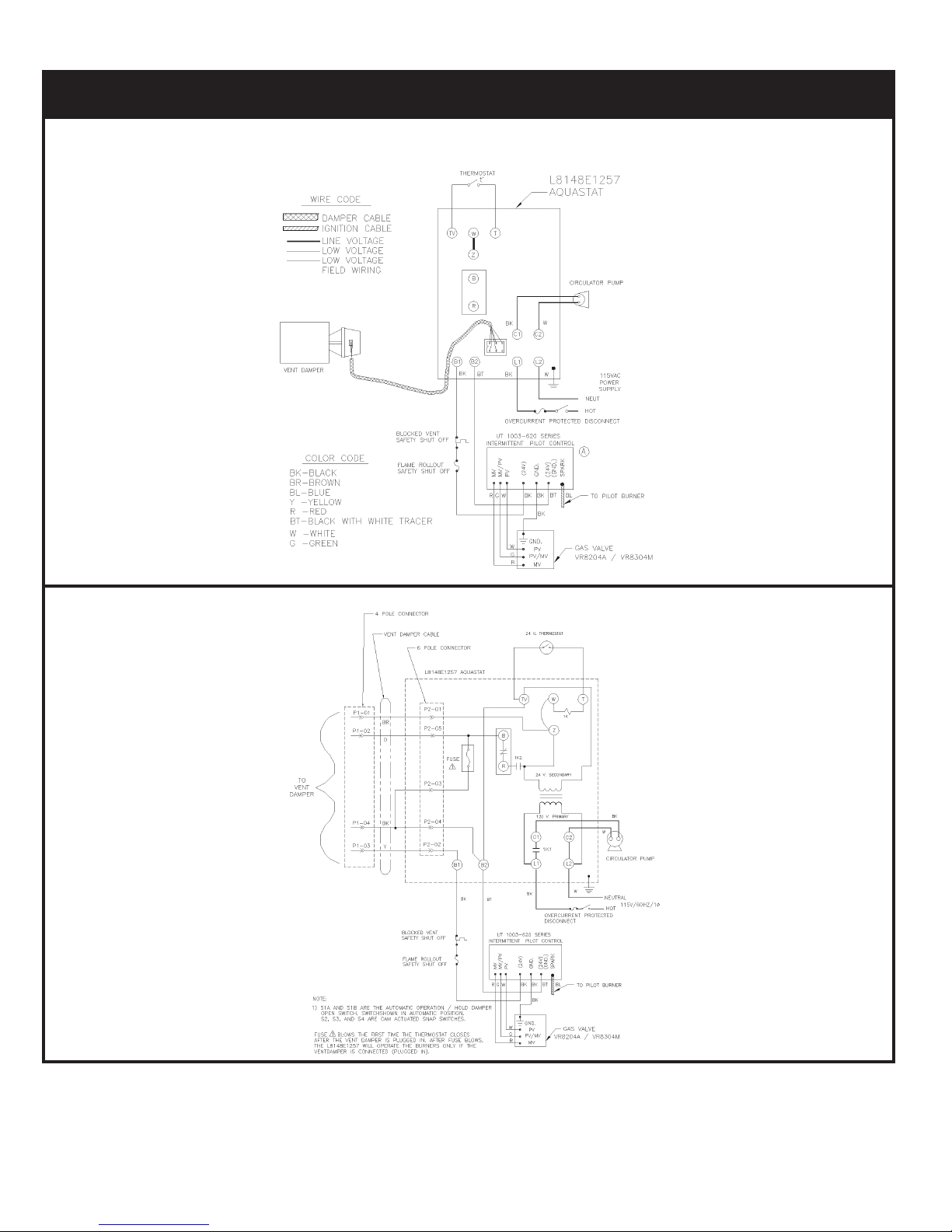
WIRING DIAGRAMS FOR HOT WATER BOILERS
INTERMITTENT IGNITION
IF ANY OF THE ORIGINAL WIRE AS SUPPLIED WITH THIS APPLIANCE MUST BE REPLACED,
IT MUST BE REPLACED WITH TYPE 105°C THERMOPLASTIC WIRE OR ITS EQUIVALENT.
NOTE: THE CIRCULATOR HARNESS IS FACTORY WIRED TO THE AQUASTAT. THIS HARNESS
NEEDS TO BE CONNECTED TO THE CIRCULATOR IN THE FIELD.
12
Page 13

WIRING DIAGRAMS FOR HOT WATER BOILERS
STANDING PILOT
IF ANY OF THE ORIGINAL WIRE AS SUPPLIED WITH THIS APPLIANCE MUST BE REPLACED,
IT MUST BE REPLACED WITH TYPE 105°C THERMOPLASTIC WIRE OR ITS EQUIVALENT.
NOTE: THE CIRCULATOR HARNESS IS FACTORY WIRED TO THE AQUASTAT. THIS HARNESS
NEEDS TO BE CONNECTED TO THE CIRCULATOR IN THE FIELD.
13
Page 14

Equipment and Optional Accessories - What They Do
RELIEF VALVE
You must have a relief valve on your boiler. Water expands as
it is heated. If there is no place for the water to expand into,
water pressure will build up inside the boiler and system. Should
this happen, the relief valve will automatically open at a
predetermined pressure. This will relieve the strain on the boiler
and system. Run a pipe from the relief valve outlet (pipe must
be same size as outlet and the open end must not be threaded)
to an open drain, tub or sink, or other suitable drainage point
not subject to freezing. Failure to do so may cause water
damage or injury should relief valve release.
EXPANSION TANK
In a properly assembled system, the expanding water flows
into a expansion tank. This tank should be of the correct size.
The tank is filled with air. As the water expands it compresses
the air in the tank to form an air pressure cushion. This “springlike” cushion serves to maintain correct operating water
pressure regardless of water temperature. This assures a “full
measure” of a water, even in the highest radiation unit of the
system. It also prevents blowing off of the relief valve.
The air in the tank in the beginning (with system filled with cold
water) is sufficient for proper operation. The tank also serves
as a trap for excess air in the system. The air would cause
gurgling in the pipes and inefficient circulation in the radiators
if left in the system . It is possible for a tank to become
“waterlogged” (filled with water). It can also become overfilled
with air. This can happen after filling the system with new water.
Fittings provided on the tank and in the line to the tank are for
bleeding off excess water or air.
When installing this tank, it is important:
1) That the tank be higher than the boiler top.
2) That the pipe to the tank continuously rises up to the tank
(so that air can “bubble” up to it).
DIAPHRAGM TYPE EXPANSION TANK
The diaphragm type expansion tank (EX-TROL) takes the place
of the conventional expansion tank. Carefully read the
instructions packed with your EX-TROL tank assembly.
The EX-TROL tank comes to you with a 10-12 pounds per square
inch air charge. This is the same as the pressure produced in
the system by the automatic fill valve. When the system is first
filled, the EX TROL tank will contain little or no water.
As the water is heated its pressure increases. It expands into
the EX-TROL tank, compressing the air in the tank. This
compressed air cushion permits the water in the system to
expand as the temperature changes.
The diaphragm type tank can be mounted on the air purger
fitting or at any convenient place in the supply or return line.
AIR ELIMINATING FITTING (AIR PURGER)
An air purger is used to remove excess air from the system. It
is installed in the supply line. It will eliminate air from the water
before it reaches the radiators and bleed off this air.
MAIN AIR VENT FOR DOWN FLOW SYSTEMS
OR DIAPHRAGM TYPE EXPANSION TANK
Before a system is filled with water, there is air in the pipes and
radiation units. Some of it will be trapped as the system is filled .
It is possible to eliminate most of this air through the air vents
on the radiation units. A main air vent will speed and simplify
this. It should be installed on the highest point in the supply
main when all radiation is below top of boiler.
AUTOMATIC FILL VALVE
For safe, efficient operation, a hot water system must be
completely filled with water. Adding new water, when needed
can be done manually (by use of a hand valve in the water
supply line). This requires regular attention to the system’s
needs. An automatic fill valve accomplishes this without
attention. It is installed in the supply line on hot water boilers
only. The valve operates through water pressure differentials.
It does not require an electrical connection.
DRAIN VALVE
This manual valve Provides a means of draining all water from
the boiler and system. It is often installed in the 3/4” tapping at
the bottom of the end boiler section. Or it can be installed in a
tee where the return line enters the boiler.
WATER TEMPERATURE CONTROL
The water temperature limit control in the relay is adjustable
and may be set as necessary. It may be set as low as 140°F,
or as high as 240°F. This depends on the type and amount of
radiation involved and weather conditions.
CIRCULATING PUMP
Every forced hot-water system requires a circulating pump. A
separate pump or zone valve is required for each zone, if you
have a two or more zone system. This pump must have the
capacity to provide the circulation required by your system.
VENT DAMPER
This product is an automatic, motorized stack damper that has
been developed to increase the efficiency of heating system
by reducing standby losses from the heating apparatus and
the conditioned air space. The damper closes the chimney
vent when the burner is off and fully opens it when combustion
is required.
14
Page 15

ROLLOUT SWITCH
(FLAME ROLLOUT SAFETY SHUTOFF)
The rollout switch is a temperature-sensitive fuse link device.
It is located on the boiler base just outside the fire box. In the
event of heat exchanger flueway blockage causing flame to
roll out of the fire box, the fuse will blow, shutting down the flow
of gas to the main burners. The fuse does not change in
appearance when blown.
If the rollout switch blows, it must be replaced with an exact
replacement. Check heat exchanger flueways for blockage
when restoring system to operating condition. DO NOT operate
system without a rollout switch.
Starting Your Boiler
SPILL SWITCH
(BLOCKED VENT SAFETY SHUTOFF)
The spill switch is a manual reset disc thermostat with a fixed setpoint
(340° F), and normally closed contacts. It is located at the relief
opening of the integral draft diverter. In the event of chimney or
venting system blockage causing products of combustion to spill
out of the relief opening, the spill switch disc heats up and the spill
switch contacts open, shutting down the flow of gas to the main
burners by removing power to the gas valve.
In the event that the spill switch contacts open, the reset button
on the back of the switch will pop up. The spill switch must be
reset manually, after the switch has cooled off, by pushing the
reset button down. Check the venting system and chimney for
blockage when restoring the system to operating condition. DO
NOT operate the boiler without a spill switch.
HOW A HOT-WATER SYSTEM OPERATES
Your entire heating system (boiler, piping and radiation units) is
filled with water. As the water in the boiler is heated, it is pumped
from the top of the boiler through the supply main to the radiation units. The cooler water in them flows back through the return main to the boiler. This provides positive and rapid response
to the thermostat.
FILLING SYSTEM WITH WATER
Close the air vents on all radiation units. Open the valves to
these units. Make sure the boiler and expansion tank drain
cocks are closed. The air bleed screw on the tank drain fitting
should be closed. Open the valve in the line from the boiler to
the expansion tank. Open the water inlet to your boiler and
leave it open. Start with the lowest radiation unit. Open the air
vent on this unit. When all the air has escaped and water starts
to flow from the vent, close it. Go to the next radiation unit, and
repeat this process. Repeat until you have covered every
radiation unit in the system (ending up at the highest unit in the
system). If your units have automatic vents, this manual venting
is unnecessary but it will speed up the proper filling of your
system.
If your system is a closed expansion tank system, you may
leave it open to refill the system automatically as needed. Check
the temperature pressure gauge. Not the position of the hand
indicating pressure. This should be between 10 and 15 lbs.
Any lowering of this movable hand below 10 lbs. Will indicate
loss of water due to leakage. The automatic fill valve should
compensate for this. Instructions are packages with the valve.
WARNING
Never run water into a hot empty boiler.
15
Page 16

For Your Safety Read Before Operating
WARNING: If you do not follow these instructions exactly, a fire or explosion
may result causing property damage, personal injury or loss of life.
A. Some boilers are equipped with an intermittent ignition
device which automatically lights the pilot. Do not try to
light the pilot by hand.
Some boilers are equipped with a continuous pilot and must
be manually lighted. (See operating instructions on page
16-18.) A match holder is included in the parts bag.
B. BEFORE OPERATING smell all around the appliance
area for gas. Be sure to smell next to the floor because
some gas is heavier than air and will settle on the floor.
WHAT TO DO IF YOU SMELL GAS
• Do not try to light any appliance.
• Do not touch any electric switch; do not use any phone
in your building.
• Immediately call your gas supplier from a neighbor’s phone.
Follow the gas supplier’s instructions.
• If you cannot reach your gas supplier, call the fire
department.
C. Use only your hand to push in or turn the gas control knob.
Never use tools. If the knob will not push in or turn by hand,
don’t try to repair it, call a qualified service technician. Force
or attempted repair may result in a fire or explosion.
D. Do not use this appliance if any part has been under water.
Immediately call a qualified service technician to inspect
the appliance and to replace any part of the control system
and any gas control which has been under water.
Intermittent Ignition Boiler - VR8204A/VR8304M Gas Valve Operating Instructions
1. STOP! Read the safety information above.
2. Set the thermostat to lowest setting.
3. Turn off all electric power to the appliance.
4. This appliance is equipped with an ignition device
which automatically lights the pilot. Do not try to
light the pilot by hand.
7. Wait five (5) minutes to clear out any gas. Then smell for
gas, including near the floor. If you smell gas, STOP! Follow
“B” in the safety information on page 19 If you don’t smell
gas, go to next step.
8. Rotate the gas control knob counterclockwise
to “ON.”
9. Replace lower front panel.
10. Turn on all electric power to the appliance.
11. Set thermostat to desired setting.
12. If the appliance will not operate, follow the instructions “To
Turn Off Gas To Appliance” and call your service technician
or gas supplier.
5. Remove lower front panel.
6. Rotate the gas control knob clockwise
to“OFF”
TO TURN OFF GAS TO APPLIANCE
1. Set the thermostat to lowest setting.
2. Turn off all electric power to the appliance if service is to
be performed.
3. Push in gas control knob slightly and turn clockwise
to “OFF” Do not force.
16
Page 17

Continuous Pilot Boiler - VR8200A/VR8300A Gas Valve Operating Instructions
1. STOP! Read the safety information on page 16.
2. Set the thermostat to lowest setting.
3. Turn off all electric power to the appliance.
4. Remove lower front panel.
5. Rotate gas control knob slightly and turn clockwise
to “OFF”
6. Wait five (5) minutes to clear out any gas. Then smell for
gas, including near the floor. If you smell gas, STOP! Follow
“B” in the safety information on page 19 If you don’t smell
gas, go to next step.
7. Find pilot - follow metal tube from gas control. The pilot is
between two burner tubes as shown in Fig. 14 on page 18.
8. Turn knob on gas control counterclockwise to
“PILOT”
9. Rotate the gas control knob counterclockwise
to “PILOT” Push down and hold the red reset button while
you light pilot burner with a match.
After about one minute, release reset button. Pilot should
remain lit. If it goes out, turn gas control knob clockwise
to OFF To relight, repeat steps 5-9.
• If button does not pop up when released, stop and
immediately call your service technician or gas supplier.
• If the pilot will not stay lit after several tries, turn the gas
control knob to “OFF” and call your service technician or
gas supplier.
10. After pilot remains lit when red reset button is released,
turn gas control knob counterclockwise to “ON.”
11. Replace lower front panel.
12. Turn on all electric power to the appliance.
13. Set thermostat to desired setting.
TO TURN OFF GAS TO APPLIANCE
1. Set the thermostat to lowest setting.
2. Turn off all electric power to the appliance if service is to
be performed.
3. Push in gas control knob slightly and turn clockwise
to “OFF” Do not force.
Operating Your Boiler
AUTOMATIC GAS VALVE
The Automatic Gas Valve opens or closes according to the
heat requirements of the thermostat and temperature limit
control. It closes if the pilot goes out. Each individual control
must be operating correctly before any gas can pass to the
burners. Any one control can hold the gas supply from burner
regardless of the demand of any other control.
SAFETY PILOT
Safety Pilot prevents the flow of gas to burner if the pilot goes
out, or will not ignite.
GAS VALVE SAFETY SHUTDOWN TEST
1. For boilers equipped with continuous pilot, with main burners
firing, disconnect the thermocouple from the gas valve. The
gas valve should immediately shut off the main burners and
the pilot.
2. For boilers equipped with intermittent ignition, with main
burners firing, disconnect the ignition cable from the
intermittent pilot control box. The gas valve should shut off
the main burners.
TURN OFF ELECTRIC POWER to boiler before
reconnecting ignition cable, to prevent electric shock.
RELIGHT
The electric and gas shall be off for 5 minutes before relighting.
THERMOSTAT
Keep it set at a desired room temperature. If windows are to
be opened or heat is not needed, move thermostat pointer to a
lower setting.
NOTE
In the event of failure of any component, the system will not
operate or will go into safety lockout. The system is
completely self-checking. On every call for heat, each
component must be functioning properly to permit operation.
On safety lockout the system has to be reset by turning the
thermostat to the lowest setting for one minute, then back
to the normal setting.
Safe lighting and other performance criteria were met with
the gas manifold and control assembly provided on the boiler
when the boiler underwent tests specified in ANSI Z21.13 latest revision.
17
Page 18
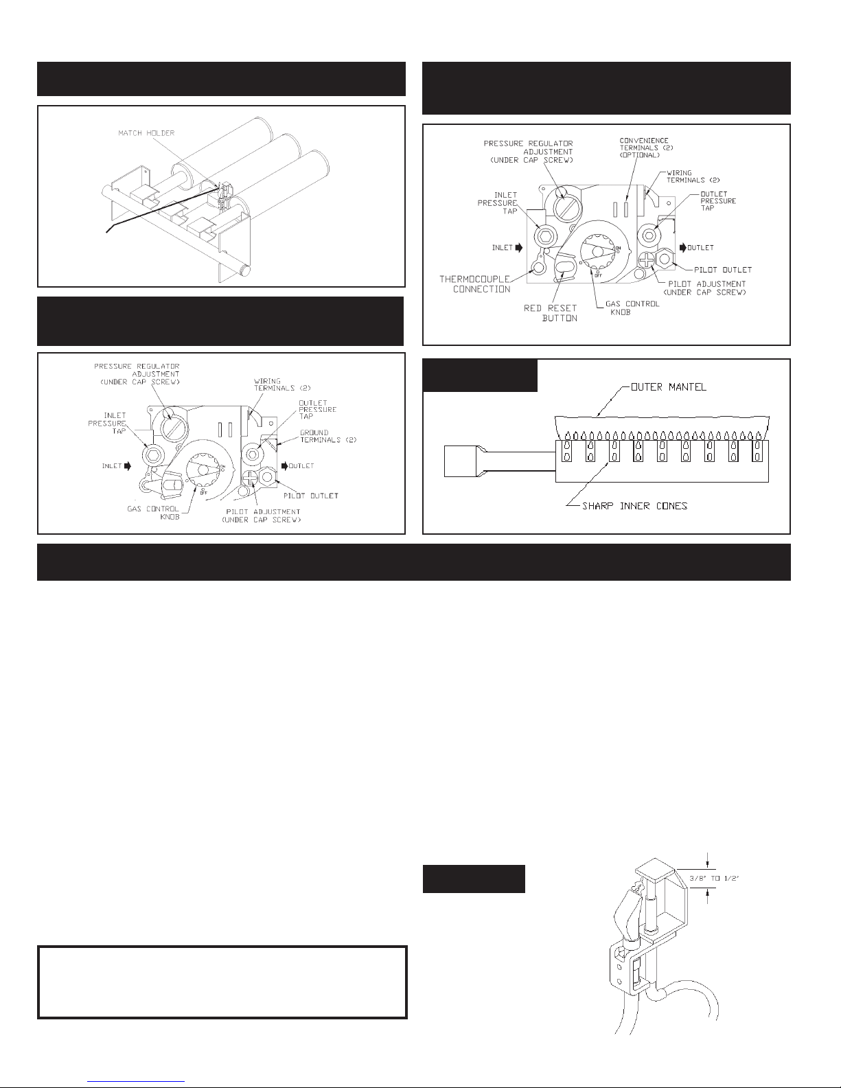
FIG. 14 - LIGHTING PILOT
FIG. 16 -VR8204A/VR8304M AUTOMATIC
GAS VALVE
FIG. 15 -VR8200A/VR8300A AUTOMATIC
GAS VALVE
FIG. 17
Checking and Adjusting
ADJUST PILOT BURNER
Pilot flame should surround 3/8" to 1/2" of the pilot sensor.
Refer to Fig. 18. If flame needs adjusting, do it as follows:
1. Remove screw cover over pilot adjusting screw.
2. Insert small screwdriver and adjust flame as needed. Turn screw
counterclockwise to increase flame, clock-wise to decrease.
3. Replace screw cover over pilot adjusting screw.
MAIN BURNER(S)
The main burners do not require primary air adjustment and
are not equipped with primary air shutters. Main burner flames
should form sharp blue inner cones in a softer blue outer mantel,
with no yellow. Puffs of air from blowing on the flame or
stamping on the floor will cause the flames to turn orange
momentarily. This is not unusual. Remain still when observing
the main burner flames. If the flame appearance is not correct,
check main burner orifices and the burner throat and flame
ports for dust and lint obstruction. It may be necessary to
remove the rollout shield to observe the main burner flames.
Replace rollout shield after observation. Refer to Figure 17.
ADJUST LIMIT CONTROLS
Instructions for each control are included with the controls.
These settings can be changed after you have had some
RECOMMENDED BOILER WATER TEMPERATURES
Type of Heating Unit Limit Control Setting
Standing Radiators...................................180º F.
Baseboard and Convector Radiators........200º F.
idea how the system works. Example: If your system does not
give quite enough heat in very cold weather, you can raise the
limit setting to 220° F Use the boiler gauge to check your
settings. Make the adjustments according to its readings. Check
thermostat operation. When set above temperature indicated
on the thermometer, boiler should ignite. Make certain the
thermostat turns off the boiler when room temperature reaches
the selected setting and starts the boiler operating when room
temperature falls a few degrees.
After setting limit control to limit setting, check to see if it shuts
off the gas supply to the burners. Turn your thermostat up to call
for heat and let your boiler run until the temperature of the water
reaches the limit setting. The gas valve should shut off and the
circulator keep running until the thermostat is satisfied, or the
water cools enough to restart the burners through the limit control.
Finally, set the thermostat for the desired temperature. Special
conditions in your home and the location of the thermostat will
govern this setting.
FIG. 18
18
Page 19

Maintaining Your Boiler
BURNERS
A visual check of the pilot end main burner flames should be
made at least once each year, preferably at the beginning of
the heating season. See page 21
RELIEF VALVE
This valve should open automatically if the system pressure
exceeds the pressure rating (usually 30 psi) of the relief valve.
Should it ever fail to open under this condition, shut down your
system. Drain the system until system pressure is reduced
below the relief valve pressure rating. If valve discharge occurs, or if valve fails to open as described above, contact an
authorized contractor or qualified service technician to replace
the relief valve and inspect the heating system to determine
the cause, as this may indicate an equipment malfunction.
This valve should be tested every month during periods of boiler
operation, and at the beginning and end of any extended nonservice period. Prior to testing, make certain discharge pipe is
properly connected to valve outlet and arranged so as to contain and safely dispose of boiler discharge. Test at normal system operating pressure. Hold the trip lever fully open for at
least five seconds in order to flush free any sediment that may
lodge on the valve seat. Then permit the valve to snap shut.
EXPANSION TANK
As previously noted, this tank may become waterlogged, or
may receive an excess of air. Frequent automatic opening of
the relief valve indicates water logging. A high boiler temperature accompanied by unusually low radiation unit temperature
(and “knocking”) indicates excess air in tank.
To correct either condition, close the valve between the boiler
and the tank. Drain the tank until it is empty. Check all the tank
plugs and fittings. Tighten as necessary. Open the valve between the boiler and tank. Water will rise to the normal height
in the tank if you have an automatic fill valve (otherwise, manually refill the system).
BOILER FLUE PASSAGES
Under normal operating conditions, with the burners properly
adjusted, it should not be necessary to clean the boiler flue
gas passages. However, to assure trouble-free operation, we
recommend that you have the flue passages, burner
adjustment, and operation of the controls checked once each
year by a competent Service Technician.
Before the start of each season (or whenever system has
been shut down for some time) recheck the whole system for
leaks ... and recheck the boiler and vent pipe for leaks. Replace
or patch any boiler seals that are faulty.
VENT PIPE
The venting of this unit is very important and the piping
should be checked at least once a season. If the vent piping
shows any sign of leaking, replace it immediately.
WATER SYSTEM
If system is to remain out of service during freezing weather,
always drain it completely (water left in to freeze will crack the
pipes and/or boiler).
CLEANING YOUR BOILER AND BURNERS
Flue passages between sections should be examined yearly
and cleaned if necessary. To clean, remove burners, pilot, and
vent pipe, Remove top and front jacket panels. Remove the
two screws attaching the intermediate front panel to the left
and right side jacket panels. Remove the draft diverter and
intermediate front panel as a unit. Carefully remove the cerafelt
gasket strips. Clean passageways between sections with a
flexible handle wire brush. Remove dirt from bottom of boiler
and from between sections by vacuuming. Make sure all flame
ports in burners are open and clear. Shake out or blow out all
loose dirt in burners. Reseal seams between adjacent sections
as necessary with 400° F RTV silicone sealant. Reassemble
all parts. Be sure to check tightness of pilot connections and
condition of burner flames after reassembly (see Figures 17
and 18). Be sure vent pipe connections to chimney are secure
and no obstructions are present.
CIRCULATOR PUMP ISOLATION VALVES
The isolation valves in the circulator pump flanges should be
operated manually once or twice per year to prevent the valves
from becoming stuck in the open position Rotate the valves
from the open position to the closed position and back to the
open position.
19
Page 20

Service Hints
You may avoid inconvenience and service calls by checking these points before you call for service.
FOR YOUR SAFETY
WHAT TO DO IF YOU SMELL GAS
1. Do Not try to light any appliance.
2. Do not touch any electric switch, do not use the phone.
3. Leave the building immediately, then call your gas supplier.
4. If you cannot reach the gas supplier, call the fire department.
IF YOUR SYSTEM IS NOT HEATING OR NOT GIVING ENOUGH HEAT . . .
Possible Cause What to do
Thermostat is not set correctly Reset thermostat above room temperature
Burner is not operating properly Check flame. If it is yellow, the burner is not getting enough air.
Or, if flame is blue and noisy and seems to lift off the burner, the
burner is getting too mush air. Contact your service technician.
No electric power to boiler Check overcurrent protection. Check to be sure electric power
supply circuit is “ON”.
Controls out of adjustment Reset according to instructions.
Radiators not heating Open radiator vents to excess air. Check flow control valve (if
used). It may be in closed position.
Circulating pump not running Check overcurrent protection. Check relay operation.
Poor electrical contact Check all control terminals and wire joints.
Rollout switch blown Have your service technician check heat exchanged for blockage.
Replace rollout switch with exact replacement.
Spill switch blown Have your service technician check venting system and chimney
for blockage, or down draft condition. Reset spill switch.
Vent damper not operating Consult troubleshooting guide in Effikal manual, packaged with
vent damper.
IF BURNER IS NOISY . . .
Possible Cause What to do
Gas input amount is incorrect Contact your service technician.
RELIEF VAVLE LEAKING . . .
Possible Cause What to do
Dirt on seat Open valve manually. Allow water to run and clear valve seat.
Water logged expansion tank Drain tank, see instructions.
HAVE YOUR SERVICE TECHNICIAN CHECK ANY PROBLEM YOU ARE UNABLE TO CORRECT.
20
Page 21

Repair Parts
GAS – FIRED HOT WATER BOILERS
– IMPORTANT –
READ THESE INSTRUCTIONS BEFORE ORDERING
All parts are listed in the following Parts List may be
ordered through your nearest supplier.
When ordering parts, first obtain the Model Number from the
data plate on your boiler, than determine the Part No. (not
the Key No.) and the Description of each part from the
following illustrations and list. Be sure to give us all this
information:
The Part No. – The Part Description – The Boiler Model No.
JACK ET - SECTION AND B ASE PARTS
T HIS IS A REPAIR PARTS LIST - NO T A PACKAGING LIST
KEY
NO.
1 Jacket, Right Side Panel 425-00-901 425-00-901 425-00-901 425-00-901 425-00-901 425-00-901 425-00-901 425-00-901
2 #10 x 1/2 Sheet Metal Screw 146-95-074 146-95-074 146-95-074 146-95-074 146-95-074 146-95-074 146-95-074 146-95-074
3 Rating Plate 146-80-901 146-80-901 146-80-901 146-80-901 146-80-901 146-80-901 146-80-901 146-80-901
4 Base Insulation - Base Sides (2) 146-14-020 146-14-130 146-14-130 146-14-130 146-14-130 146-14-130 146-14-130 146-14-130
5 Base Baffle 425-00-642 425-00-643 425-00-644 425-00-645 425-00-646 425-00-647 425-00-648 425-00-649
6 Base 425-00-662 425-00-663 425-00-664 425-00-665 425-00-666 425-00-667 425-00-668 425-00-669
7 Jacket Tie Bar 425-00-652 425-00-653 425-00-654 425-00-655 425-00-656 425-00-657 425-00-658 425-00-659
8 Push Nipple 433-00-976 433-00-976 433-00-976 433-00-976 433-00-976 433-00-976 433-00-976 433-00-976
9 Jacket, Left Side Panel 425-45-900 425-45-900 425-45-900 425-45-900 425-45-900 425-45-900 425-45-900 425-45-900
10 Knob, Service Door (Pair) 137-02-513 137-02-513 137-02-513 137-02-513 137-02-513 137-02-513 137-02-513 137-02-513
11 Jacket, Service Door 425-00-912 425-00-913 425-00-914 425-00-915 425-00-916 425-00-917 425-00-918 425-00-919
12 Jacket, Int'd. Panel 425-00-812 425-00-813 425-00-814 425-00-815 425-00-816 425-00-817 425-00-818 425-00-819
13 Jacket, Front Panel 425-00-810 425-00-811 425-00-804 425-00-805 425-00-806 425-00-807 425-00-808 425-00-809
14 1/4" Tie Rod, Nut 146-05-008 146-05-001 146-05-002 146-05-051 146-05-053 146-05-005 146-05-007 146-05-009
15 Boiler Section, Left 410-00-020 410-00-020 410-00-020 410-00-020 410-00-020 410-00-020 410-00-020 410-00-020
16 Boiler Section, Middle ---- 410-00-021 410-00-021 410-00-021 410-00-021 410-00-021 410-00-021 410-00-021
17 Jacket, Top Panel 425-45-842 425-45-843 425-45-844 425-45-845 425-45-846 425-45-847 425-45-848 425-45-849
18 Draft Diverter 425-00-672 425-00-673 425-00-674 425-00-675 425-00-676 425-00-677 425-00-678 425-00-679
19 Boiler Section, Right 410-00-021 410-00-021 410-00-021 410-00-021 410-00-021 410-00-021 410-00-021 410-00-021
20 Jacket, Back Panel 425-00-902 425-00-903 425-00-904 425-00-905 425-00-906 425-00-907 425-00-908 425-00-909
‡ Jacket Complete 425-00-922 425-00-923 425-00-924 425-00-925 425-00-926 425-00-927 425-00-928 425-00-929
‡ Block Assembly (19, 16, 15, 14, 8) 410-00-213 410-00-313 410-00-413 410-00-513 410-00-613 410-00-713 410-00-813 410-00-913
‡ Combustable Floor Plate 146-14-031 146-14-031 146-14-031 146-14-031 146-14-031 146-14-032 146-14-032 146-14-032
‡ Cerafelt Gasket 146-14-018 146-14-018 146-14-018 146-14-018 146-14-018 146-14-018 146-14-018 146-14-018
21 Vent Damper 118-20-04 118-20-05 118-20-06 118-20-06 118-20-07 118-20-07 118-20-07 118-20-07
‡ Base Assembly (6, 5, 4) 433-00-662 433-00-663 433-00-664 433-00-665 433-00-666 433-00-667 433-00-668 433-00-669
‡ Not illustrate d
DESCRIPTION
- Base Front 146-14-112 146-14-113 146-14-114 146-14-115 146-14-116 146-14-117 146-14-118 146-14-119
- Base Rear 146-14-122 146-14-123 146-14-124 146-14-125 146-14-126 146-14-127 146-14-128 146-14-129
2 SECTION 3 SECTION 4 SECTION 5 SECTION 6 SECTION 7 SECTION 8 SECTION 9 SECTION
Part No . Part No. Part No. Part No. Part No. Part No. Part No. Part No.
21
Page 22

Repair Parts
GAS BURNERS AND MANIFOLD PARTS
(FOR USE WITH NATURAL GAS AND PROPANE)
NOTE: Actual gas valve may look different than gas valve shown.
GAS BURNERS AND MANIFOLD PARTS - NATURAL GAS AND PROPANE
ITEM DESCRIPTION 2 SECTION 3 SECTION 4 SECTION 5 SECTION 6 SECTION 7 SECTION 8 SECTION 9 SECTION
24 V Gas Va lve, El ect . Ignit i on - Nat . 146-62-052 146-62 -052 146-62-052 146-62-052 146-62-05 8 146-62-058 146-62-058 14 6-62-058
1
24 V Gas Va lve, El ect . Ignit i on - LP 146-62-062 146-62-062 146-62-06 2 146-62-062 146-62-059 14 6-62-059 146-62-059 146-62-059
2 Pil ot Tube w/F i t tings 433-00-201 433-00-201 43 3-00-201 433-00-201 433-00-201 433-00-201 433-00-200 433-00-200
3 10-32 ½ Hex Hd. S c rew (2) 146-95-307 146-95 -307 146-95-307 146-95-307 1 46-95-307 146-95-307 146-95-307 14 6-95-307
Gas M an ifol d - Nat . 146-16-032 146-16-033 14 6-16-034 146-16-035 146-16-013 14 6-16-014 146-16-015 146-16-016
4
Gas M an ifol d - LP 146-16-009 146-16-010 146-16-01 1 146-16-012 146-16-013 14 6-16-014 146-16-015 146-16-016
Main Burner Orifice - Nat . * 146-15-041 146-15-041 146-15-041 146 -15-041 146-15-042 146-15-042 146-15-042 146-15-042
5
Main Burner Orifice - LP* 146-1
6 M ai n Burner** --- 146-15-532 146-15-53 2 146-15-532 146-15-532 14 6-15-532 146-15-532 146-15-532
6A Mai n Burner wit h Pil ot B racket ** 146-15-531 146-15-531 14 6-15-531 146-15-531 146-15-531 14 6-15-531 146-15-531 146-15-531
Pil ot B urner - Nat . 146-62-095 146-62-092 14 6-62-092 146-62-092 146-62-092 146-62-092 146-62-092 146-62-092
7
Pil ot B urner - LP 146-62-093 146-62-094 14 6-62-094 146-62-094 146-62-094 146-62-094 146-62 -094 146-62-094
+ Rollout S hield 425-00-932 425-00-933 425-00-93 4 425-00-935 425-00-936 42 5-00-937 425-00-938 425-00-939
5-043 146-15-043 146-15-043 146-15-043 146-15-043 146-15-043 146-15-043 146-16-043
ALTERNATE PARTS FOR CONTINUOUS PILOT
ITEM DESCRIPTION 2 SECTION 3 SECTION 4 SECTION 5 SECTION 6 SECTION 7 SECTION 8 SECTION 9 SECTION
24 V Gas Va lve, Cont in uous Pilot - Nat . 146-62-051 146-62 -051 146-62-051 146-62-051 1 46-62-060 146-62-060 146-62-060 146-62-060
1
24 V Gas Va lve, Cont in uous Pilot - LP --- 146-95-301 146-95-301 146-95-301 1 46-95-301 146-95-301 146-95-301 14 6-95-301
Pil ot B urner - Nat . 146-62-098 146-62-098 14 6-62-098 146-62-098 146-62-098 146-62-098 146-62-098 146-62-098
7
Pil ot B urner - LP --- 146-62-096 146-62-09 6 146-62-096 146-62-096 14 6-62-096 146-62-096 146-62-096
Thermocouple - Nat . 146-62-037 146-62-037 146-62-039 146-62-039 146-62-03 9 146-62-039 146-62-036 146-62-036
+
Thermocouple - LP --- 146-62-037 146-62-039 146-62-039 1 46-62-039 146-62-039 146-62-036 146-62-036
* Requires 1 l ess t h an t he nu m ber of se c tion s .
NOTE:
** Requires 2 less t h an t he num b er of sect i on s .
+ Not Illustrated
22
Page 23

Repair Parts
BOILER CONTROLS AND PIPING
Key
No.
1 ¾ ” AS M E Relief Val ve 146-22-011
2 ¾ ” x 7½ ” Ni ppl e 146-07-041
3 Temperat ure P essure Gauge - 5" S tem 146-23-009
6 1¼ ” x ¾ ” x 1 ¼” Tee 151-00-01
7 A quast at Relay 101-00-02
8 Is ol at i on Ball Valve 146-26-043
‡ Grundfos UP15-42F Circulator CI-006.01
9 Taco 007 Ci rc u la t or CI-001.03
10 1¼” x 2½” Ni ppl e 146-07-044
11 1¼” B ent Ret urn Nippl e 146-07-003
12 Interm i ttent Pil ot Control 146-62-070
‡ S p i l l Sw i tc h (36TX16-6281) 340° F 146-60-002
‡ Rollout S wit c h 146-29-002
‡ 4" Vent Dam per (w 3" A dapter) 118-20-04
‡ 5" Vent Dam per 118-20-05
‡ 6" Vent Dam per 118-20-06
‡ 7" Vent Dam per 118-20-07
‡ V e nt Damper O p erator (Motor) 1 14-00-02
‡ 400° F Black S i licone Rubber Adhesive
Seal ant (10. 3 oz. Cartri dge )
‡ Not illustrated
Description
Part
No.
146-06-020
Note: the circulator and ball valves do not come
pre-installed.”
23
Page 24

14683002 Rev.3, November 2004
 Loading...