

Dunkirk PSB-3D, PSB-3DP, PSB-4D, PSB-4DP, PSB-5D Installation, Operation & Maintenance Manual
...
MODELS
PSB-3D
PSB-3DP
PSB-4D
PSB-4DP
PSB-5D
PLYMOUTH STEAM SERIES 2
GAS-FIRED
STEAM BOILERS
INSTALLATION, OPERATION &
MAINTENANCE MANUAL
PSB-5DP
PSB-6D
PSB-6DP
PSB-7D
PSB-7DP
PSB-8D
PSB-8DP
PSB-9D
PSB-9DP
MODEL PSB
Electronic
Intermittent
Ignition
ECR International, Inc.
2201 Dwyer Avenue,
Utica NY 13501
www.ecrinternational.com
P/N 14683003, Rev. D [08/03/2015]
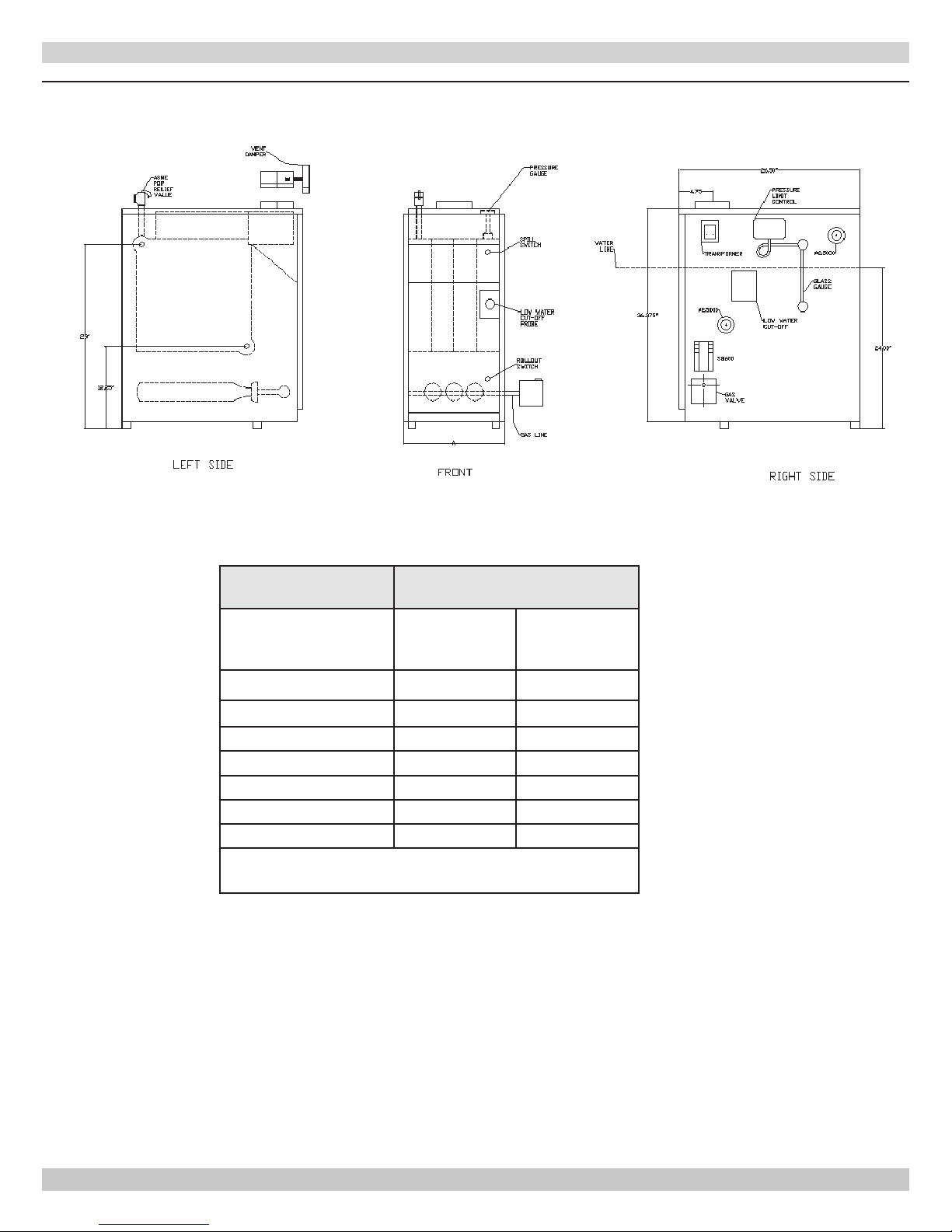
Figure 1 - Dimensions
DIMENSIONS
BOILER MODEL
NUMBER
(1)
Dimensions (Inches)
Intermittent
Ignition w/Vent
Flue Diameter "A" Width
Damper
PSB-3D 5 11¼
PSB-4D 6 14½
PSB-5D 6 17¾
PSB-6D 7 21
PSB-7D 7 24¼
PSB-8D 7 27½
PSB-9D 7 30¾
Add 5½" to height for Vent Damper
(1)
Add model number sufx 'P' for Propane Gas.
2
P/N 14683003, Rev. D [08/03/2015]
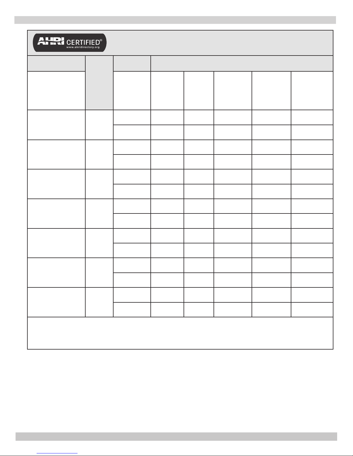
RATINGS AND CAPACITY
Table 1 - Ratings and Capacities
BOILER MODEL
NUMBER
Intermittent
Ignition w/Vent
Damper
(1)
PSB-3D
(1)
PSB-4D
(1)
PSB-5D
(1)
PSB-6D
No. of
Sec.
3
4
5
6
†Natural Gas
Fuel Type
Input
*MBTUH
Natural Gas 75 62 82.7 47 196
Propane 70 58 82.7 44 183
Natural Gas 112 91 82.0 68 283
Propane 105 85 80.4 64 267
Natural Gas 150 122 82.0 92 383
Propane 140 114 80.6 86 358
Natural Gas 187 153 82.0 115 479
Propane 175 143 80.9 107 446
Heating
Capacity
*MBTUH
AFUE(%)
Net AHRI
Rating *Mbh
Net AHRI
Rating Sq. Ft.
Natural Gas 225 183 82.0 137 571
(1)
PSB-7D
7
Propane 210 171 81.1 128 533
Natural Gas 262 214 82.0 161 671
(1)
PSB-8D
8
Propane 245 200 81.3 150 625
Natural Gas 299 245 82.0 184 767
(1)
PSB-9D
9
Propane 280 229 81.5 172 717
* MBH = 1,000 Btuh. Btuh = British Thermal Unit Per Hour.
† For altitudes above 2,000 ft. reduce input rate 4% for each 1,000 ft. above sea level.
Heating Capacity is based on DOE (Department of Energy) test procedure.
(1)
Add model number sufx 'P' for Propane Gas.
Net AHRI steam Ratings shown are based on a piping and pickup allowance of 1.333.
Base selection of boiler size on "Net AHRI Rating" being equal to or greater than installed radiation in square feet.
Consult manufacturer before selecting a boiler for installations having unusual piping and pickup requirements,such as
intermittent system operation, exhaust piping systems, etc.
3
P/N 14683003, Rev. D [08/03/2015]

TABLE OF CONTENTS
Dimensions ................................................ 2
Ratings and Capacity .................................. 3
Safety Symbols .......................................... 5
Locating the Boiler ...................................... 6
System Piping ............................................ 7
Installation - System Piping ........................10
Fresh Air for Combustion ............................11
Chimney and Vent Pipe Connection ..............12
Vent Damper Operation ..............................14
Gas Supply Piping ......................................15
Electrical Wiring ........................................16
Operating Instructions ................................17
Operating Your Boiler .................................18
Checking and Adjusting ..............................19
Start-up Cleaning ......................................21
General Maintenance .................................22
Service Hints ............................................23
Wiring Diagrams ........................................24
Wiring diagrams ........................................25
Controls and Accessories ............................26
Introduction
Boiler is designed for use in closed heating systems where
all steam is returned as condensate and make-up water is
minimal. Boiler is not designed for or intended for use in
open systems using 100% make-up water.
Prior to Installation
• Verify correct boiler for type of gas being used
natural or propane. See Rating Plate.
• Verify boiler size and dimensions. See Figure 1 page 2.
• Verify ratings and capacity data for natural gas. See
Table 1 page 3.
Installation Requirements
• Supply boiler with correct gas (natural or propane),
fresh air for combustion, and suitable electrical supply.
• Connect boiler to adequate venting and piping
systems.
• Provide boiler with properly located and adjusted
thermostat.
Installation of boiler in building under construction, use
precaution to insure clean combustion air supply during
construction process. Airborne particulate from construction
materials can clog burner ports and cause incomplete
combustion and sooting.
Complete all steps for safe and proper heating system
operation.
Repair Parts ..............................................27
KEEP THIS MANUAL NEAR BOILER
RETAIN FOR FUTURE REFERENCE
GAS FIRED STEAM BOILERS
Check our website frequently for updates: www.ecrinternational.com
Information and specications outlined in this manual in effect at the
time of printing of this manual. ECR International reserves the right to
discontinue, change specications or system design at any time without
notice and without incurring any obligation, whatsoever.
4
P/N 14683003, Rev. D [08/03/2015]
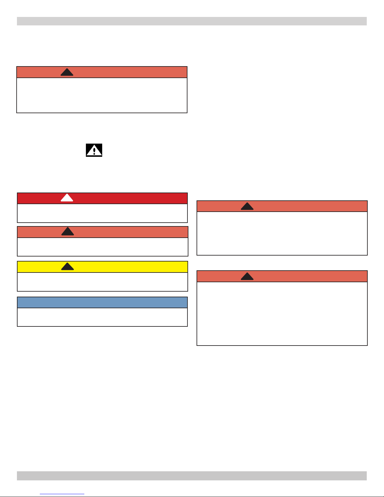
SAFETY SYMBOLS
General
Boiler and venting installation shall be completed by
qualied agency.
WARNING
!
Fire, explosion, asphyxiation and electrical shock
hazard. Improper installation could result in death
or serious injury. Read this manual and understand
all requirements before beginning installation.
Become familiar with symbols identifying potential
hazards.
This is the safety alert symbol. Symbol alerts you to
potential personal injury hazards. Obey all safety messages
following this symbol to avoid possible injury or death.
!
DANGER
Indicates a hazardous situation which, if not avoided,
WILL result in death or serious injury.
!
WARNING
Indicates a hazardous situation which, if not avoided,
could result in death or serious injury.
Installation shall conform to requirements of
authority having jurisdiction or in absence of such
requirements to the National Fuel Gas Code, ANSI
Z223.1/NFPA 54.
Where required by authority having jurisdiction,
installation shall conform to Standard for Controls
and Safety Devices for Automatically Fired Boilers,
ANSI/ASME CSD-1. Controls can be added to make
this boiler CSD-1 compliant. Check with your local
codes for requirements.
Requirements for Commonwealth of Massachusetts:
Boiler installation must conform to Commonwealth of
Massachusetts code 248 CMR which includes but is
not limited to installation by licensed plumber or gas
tter.
WARNING
!
Installing or venting a boiler or any other gas
appliance with improper methods or materials could
result in death or serious injury due to re or to
asphyxiation from poisonous gases such as carbon
monoxide which is odorless and invisible.
!
CAUTION
Indicates a hazardous situation which, if not avoided,
may result in minor or moderate injury.
NOTICE
Used to address practices not related to personal
injury.
WARNING
!
Fire, explosion, asphyxiation hazard. Keep boiler
area clear and free from combustible materials,
gasoline and other ammable vapors and liquids.
Modication, substitution or elimination of factory
equipped, supplied or specied components could
result in death or serious injury.
5
P/N 14683003, Rev. D [08/03/2015]
LOCATING THE BOILER
Locating the Boiler
1.
Select level location as centralized with piping system,
and as near chimney as possible.
2.
Place crated boiler at selected location. Remove all
crate material. Please recycle responsibly.
!
WARNING
Fire hazard. Do not install boiler on combustible
ooring or carpeting. Failure to follow these
instructions could result in death or serious injury.
3.
Do not install boiler on carpeting. For installation
on non-combustible oors only. For installation on
combustible ooring, special base must be used. See
Repair Parts page 27.
4.
Use metal shims under boiler base legs for nal leveling
if needed.
5.
Install boiler in location that permits satisfactory
combustion of gas, proper venting, and maintenance
of ambient temperature at safe limits under normal
conditions of use. Boiler location should not interfere
with proper circulation of air. Introduce outside air
if normal inltration does not provide necessary
air.“Fresh Air for Combustion” on page 11.
6.
Notify owner to keep air passages free of obstruction.
Ventilating and combustion air must enter boiler room
without restrictions.
7.
Install boiler so automatic gas ignition system
components are protected from water (dripping,
spraying, rain, etc.) during appliance operation and
service.
Table 2 -
Minimum Clearance Dimensions
Top 6"
Rear 6"
Control Side 7"
Opposite Side 6"
Front Alcove
Flue/Vent
Connector
6"
Draft Hood Installation
!
WARNING
Asphyxiation, carbon monoxide hazard. Failure to
follow these instructions could result in improper
combustion and possible leakage of combustion
products into the living space.
Follow directions given in Figure 8. Attach draft diverter,
and blocked vent switch. Mount vent damper. See
"Connecting Vent Damper and Vent Connector" page 12.
See Wiring Diagrams page 25.
6
P/N 14683003, Rev. D [08/03/2015]
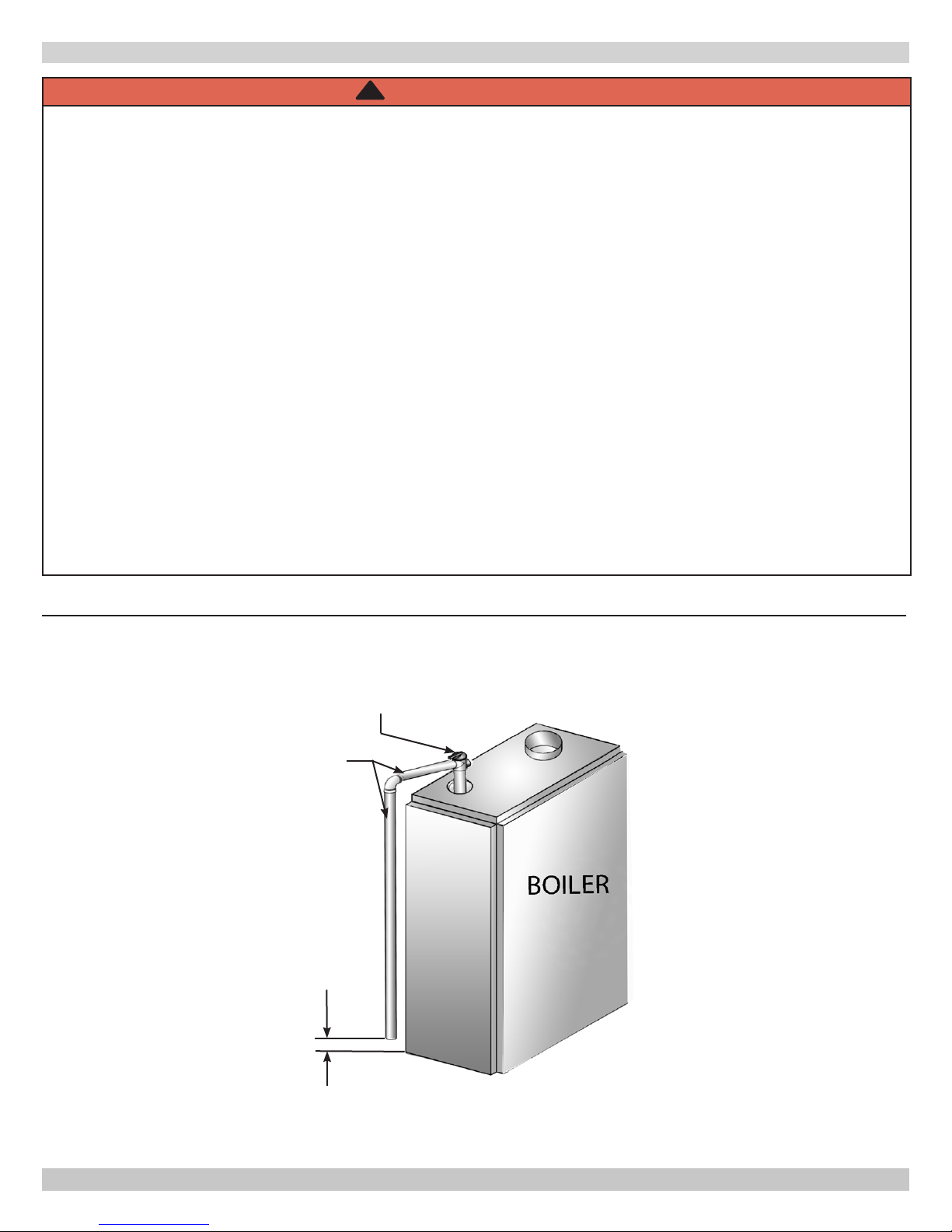
SYSTEM PIPING
!
WARNING
Burn or Scald Hazard. Discharge line shall be installed to relief valve outlet connection to avoid burns,
scalding, or water damage due to discharge of steam and/or hot water during operation.
Discharge line shall:
• Connect to safety valve outlet. Piped down to safe point of disposal. Check local codes for maximum
distance from oor or allowable safe point of discharge.
• Pipe size be of equal to or greater than of safety valve outlet over entire length of discharge line.
• Have no intervening shutoff valve between safety valve and discharge to atmosphere. Do not plug or
place any obstruction in discharge line.
• Terminate freely to atmosphere where any discharge will be clearly visible and at no risk of freezing.
• Allow complete drainage of valve and discharge line.
• Install safety valve with spindle in vertical position.
• Do not install shutoff valve between boiler and safety valve.
• Support safety valve discharge piping.
• Be short and straight as possible.
• Terminate with plain end, not threaded.
• Constructed of material suitable for exposure to temperatures of 375° F (191°C); or greater.
Refer to local codes and appropriate ASME Boiler and Pressure Vessel Code for additional installation
requirements.
Figure 3 - Safety Valve
Safety Valve
Discharge
Piping
Check local codes
for maximum
distance from
oor or other
allowable safe
point of discharge
6" Above Floor
7
P/N 14683003, Rev. D [08/03/2015]

SYSTEM PIPING
Consider near boiler piping as part of the boiler for proper
water level control and to produce dry steam.
Correct near boiler piping is crucial to proper operation of
boiler and heating system.
Follow these recommendations carefully.
1.
Place boiler in selected location as near chimney as
possible.
2.
Install safety valve. Figure 3 and Warning on Page 7.
• Install union, if used, close to safety valve outlet.
• Install elbows close to safety valve outlet and
downstream of union (if used).
3.
Boiler is equipped with two 2½" supply connections
and two 2½" return connections, one each on both left
and right sides of boiler. Plug unused connections with
furnished 2½" plug (furnished).
4.
When using both supply tappings to pipe system as
shown in Figure 5, Page 10.
• Fit headers with header offsets, swing joints, or equip
with expansion joints, so thermal expansion and
contraction of header does not damage boiler. Do not
weld headers.
13.
For pumped return systems, follow the condensate
pump or boiler feed pump manufacturer’s instructions
for proper installation and hookup.
14.
In connecting the cold water supply to the water inlet
valve, make sure that a clean water supply is available.
When the water supply is from a well or pump, a sand
strainer should be installed at the pump.
For Use With Cooling Units
Install boiler, when used in connection with refrigeration
system, so chilled medium is piped in parallel with boiler
with appropriate valves to prevent chilled medium from
entering the boiler. See Figure 6.
• Place system takeoffs from header between equalizer
and riser to header nearest equalizer. System takeoffs
must never be between two risers. If steam main goes
in two directions, place two takeoffs from header, one
for each main.
5.
System takeoffs from the header must never be
bullheaded. If the steam main goes in two directions,
there must be two takeoffs from the header, one for each
main.
6.
All boilers in gravity return systems must be equipped
with a Hartford Loop as shown in Figure 5.
7.
When piping the vertical risers from the boiler to the
header, the bottom of the header must be a minimum
of 24 inches above the water level line on the right side
of the boiler.
8.
Steam riser(s) and header shall be 2½” pipe size.
9.
Equalizer line shall be minimum 1½” pipe size.
10.
The near boiler piping shall include a 2½” tee with a
plug located on the supply line as shown for skimming
(i.e. surface blowdown).
11.
The near boiler piping shall include a 1-1/2 ball valve
in the return piping as shown for bottom blowdown and
draining.
12.
For gravity return systems, the bottom of the lowest
steam carrying pipe, be it a dry return, or the end of the
steam main, must be at least 28” above the normal water
level line on the right side of the boiler. This is known as
“Dimension A.”
8
P/N 14683003, Rev. D [08/03/2015]
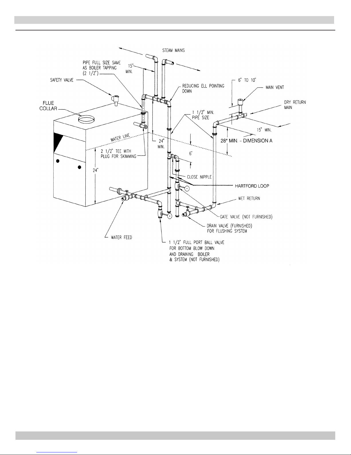
SYSTEM PIPING
Figure 4 - Recommended Near Boiler Piping Using One Supply Tapping
9
P/N 14683003, Rev. D [08/03/2015]
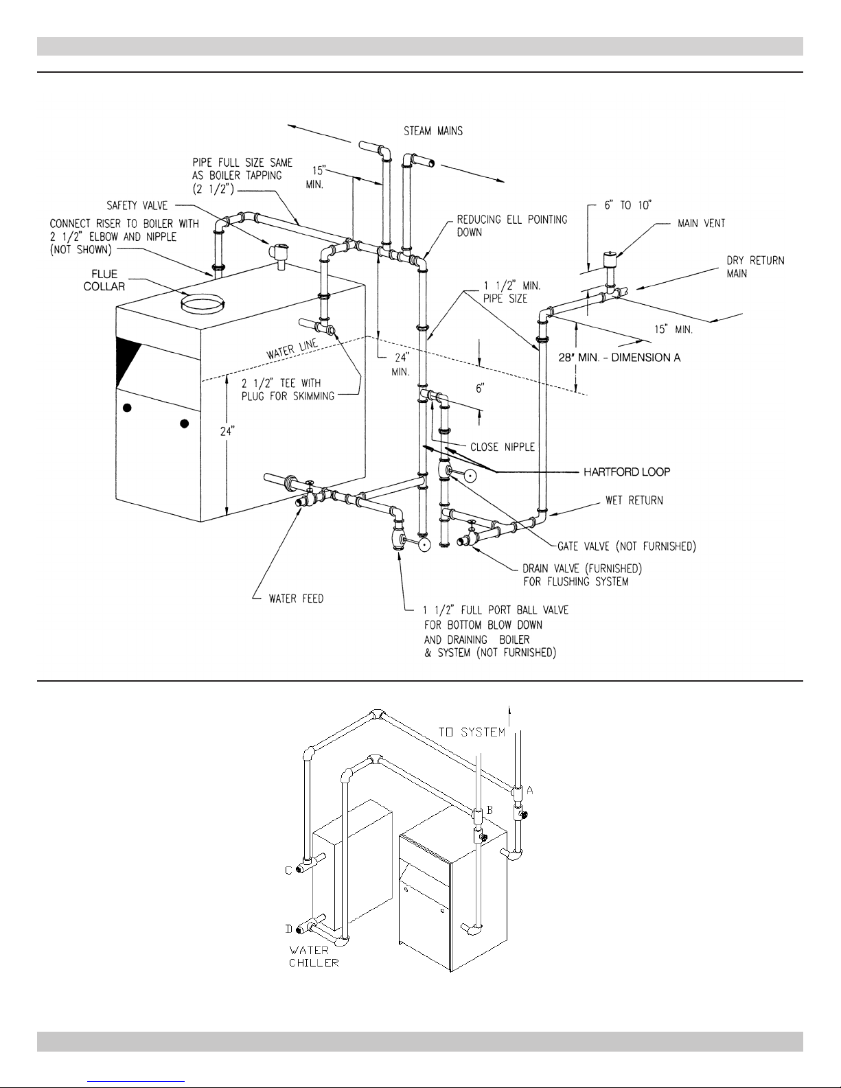
INSTALLATION - SYSTEM PIPING
Figure 5 - Recommended Near Boiler Piping Using Two Supply Tappings
Figure 6 - Chilled Water Piping
VALVES A & B OPEN FOR HEATING; CLOSE FOR COOLING
VALVES C & D CLOSE FOR HEATING; OPEN FOR COOLING
10
P/N 14683003, Rev. D [08/03/2015]
 Loading...