

Page 1
INSTALLATION INSTRUCTIONS
These instructions must be affixed on or adjacent to the boiler
Dml'v' ¢
MODEL PVSB
Continuous Pilot
Gas-Fired
Steam
Boilers
These Gas-Fired Water Boilers are low pressure, sectional
cast iron boilers Designed Certified by C.S.A. (Canadian
Standards Association) for use with Natural and Propane
Gases. They are constructed and hydrostatically tested for a
maximum working pressure of 50 psi (pounds per square
inch) in accordance with AS.ME. (American Society of
Mechanical Engineers) Boiler and Pressure Vessel Code
Section IV Standards for cast iron heating boilers.
MODEL PSB
Electronic
Intermittent
Ignition
Warning: Improper installation, adjustment, alteration, service or maintenance can cause injury or
property damage. Refer to this manual. For assistance or additional information consult a qualified
installer, service agency or the gas supplier
Page 2
Boiler Ratings and Capacities ...................... 2
Before You Start........................................ 3
Locating the Boiler .................................... 3
Fresh Air for Combustion ............................ 4
Installation - System Piping ......................... 5
Chimney and Vent Pipe Connection .............. 8
Vent Damper Operation .............................. 9
Gas Supply Piping .................................... 10
Electrical Wiring ....................................... 11
Controls and Accessories - What They Do ..... 17/
For Your Safety - Read Before Operating ....... 18
Operating Your Boiler ................................ 20
Checking and Adjusting ............................. 21
Cleaning Your Boiler ................................... 22
Maintaining Your Boiler .............................. 23
Service Hints ........................................... 24
Repair Parts ............................................. 25
LI
PRESSURE
GAUGE
r _T /_ "SWITCH I
....... SPILL
I I I_" l
WATER
I I L.E----I----
I [ ]L_\ /
LOW WATER
I _ CUT-OFF
- - -- ± _ -- PRORE
_ SW_TCH
L
GAS
;-.....A __ L,.E
'_'m RE_URE I
oo.TROL|
TRANSFORMER ------
_GAUGE
LOW WATER
_ $8600 CUT-OFF
VALVE
_u
LEFT SIDE FRONT RIGHT SIDE
24"
DESIGN
CERTIFIED FOR
NATURAL
AND PROPANE GAS
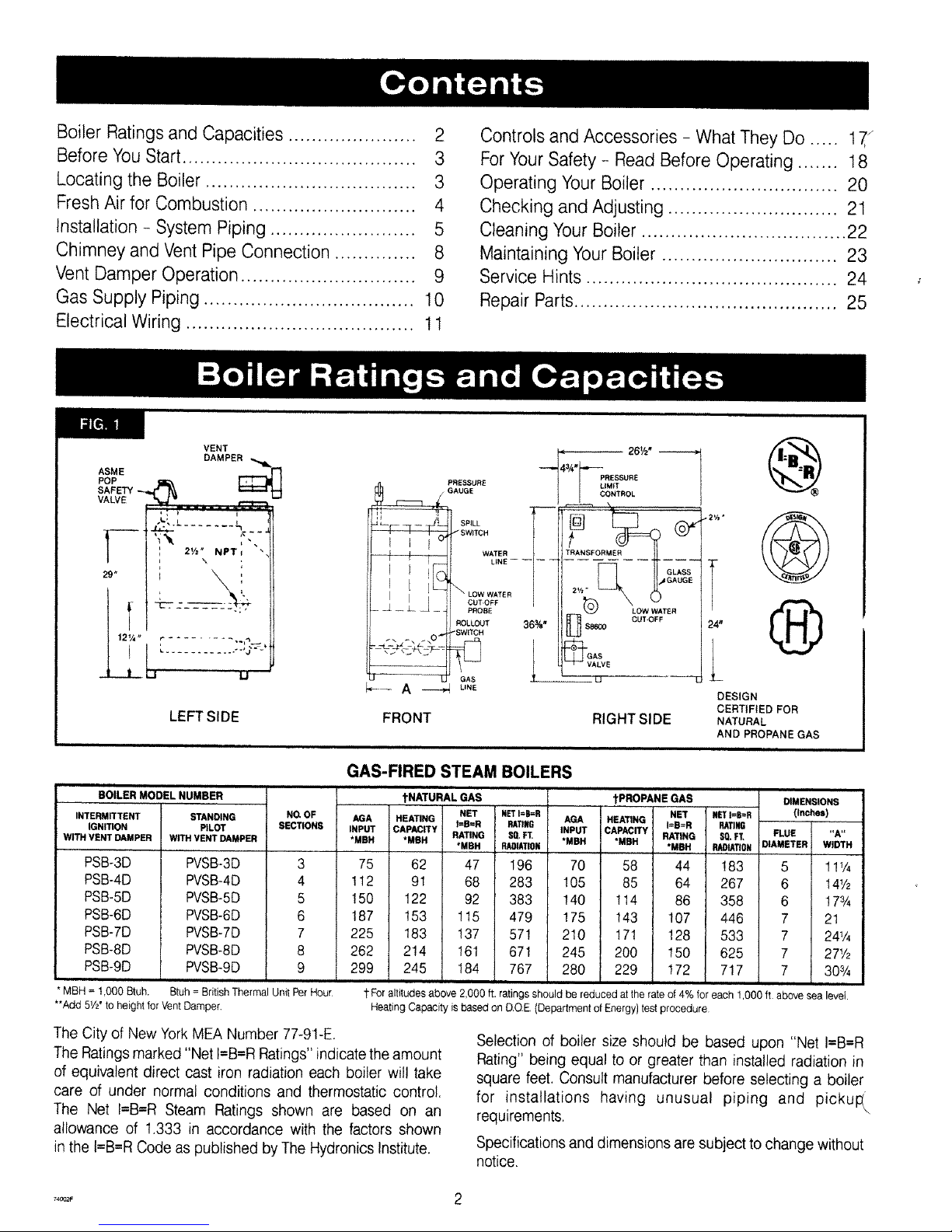
GAS-FIRED STEAM BOILERS
BOILER MODEL NUMBER tNATURAL GAS tPROPANE GAS
INTERMITTENT STANDING NG OF AGA HEATING NET #£T I=B=R NET
IGNITION PILOT SECTIONS INPUT CAPACITY I=B=R RATING AGA HEATING I=B=R
WITH VENT DAMPER WITH VENT DAMPER *MBH *MBH RATING,MBH PJ_IATIONS0'FT. INPUT,MBH CAPACITY,MBH RATING
*MBH
PSB-3D
PSB-4D
PSB-5D
PSB-6D
PSB-7D
PSB-8D
PSB-9D
PVSB-3D
PVSB-4D
PVSB-5D
PVSB-6D
PVSB-7D
PVSB-8D
PVSB-9D
3
4
5
6
7
8
9
75 62 47 196 70 58
112 91 68 283 !05 85
!50 122 92 383 !40 114
187 153 115 479 !75 143
225 183 137 571 210 !71
262 2!4 161 671 245 200
299 245 184 767 280 229
DIMENSIONS
_T I=B=R (Inches)
_TI_
_. F_ F_E "A"
PJW_TION D_METER WIDTH
44 !83 5 11%
64 267 6 14½
86 358 6 !7¾
107 446 7 21
!28 533 7 24¼
150 625 7 27½
172 717 7 30¾
* MBH = 1,000 Btuh. Btuh = British Thermal Unit Per Hour
**Add 5V_' to height for Vent Damper.
t For altitudes above 2,000 ft. ratingsshould be reduced at the rate of 4% for each 1,O00 ft above sea level.
Heating Capacity is based on DOE {Department of Energy} test procedure
The City of New YorkMEA Number 77-91-E.
The Ratingsmarked "Net I=B=RRatings" indicate the amount
of equivalent direct cast iron radiation each boiler will take
care of under normal conditions and thermostatic control.
The Net I=B=R Steam Ratings shown are based on an
allowance of 1.333 in accordance with the factors shown
in the t=B=RCode as published by The Hydronics Institute.
Selection of boiler size should be based upon "Net I=B=R
Rating" being equal to or greater than installed radiation in
square feet. Consult manufacturer before selecting a boiler
for installations having unusual piping and picku!_\
requirements.
Specifications and dimensions are subject to change without
notice.
Page 3
Checktobesureyouhavetherightsizeboilerbeforestartingtheinstallation.
_,eeratingandcapacitytableonpreviouspage.Alsobesurethenewboileris
_orthetypeofgasyouareusing.Checktheratingplateontherightsideofthe
boiler.
Youmustseethattheboilerissuppliedwiththecorrecttypeofgas,freshair
forcombustion,andasuitableelectricalsupply.Also,theboilermustbecon-
nededtoasuitableventingsystemandanadequatepipingsystem.Finally,a
thermostat,properlylocated,isneededforcontroloftheheatingsystem.Ifyou
haveanydoubtsastothevariousrequirements,checkwithlocalauthorities
andobtainprolessionathelpwhereneeded.Takethetimetocompleteallof
thestepsforSAFEandPROPERoperationoftheheatingsystem.
Ifthisboilerisinstalledinabuildingunderconstruction,specialcaremustbe
takentoinsureacleancombustionairsupplyduringtheconstructionprocess.
Airborneparticulatessuchasfromdrywalldustandfromfiberglassinsulation
canclogtheburnerportsandcauseincompletecombustionandsooting,
Theseboilersaredesignedforuseinclosedheatingsystemswhereallofthe
steamisreturnedtotheboilerascondensateandtheamountofmake-upwater
requiredisminimal.Theseboilersarenotdesignedfororintendedforusein
opensystemsofprocessapplicationsusing100%make-upwater.Damageto
theboilerresultingfromsuchuseshallnotbecoveredunderthewarranty.
Whererequiredbytheauthorityhavingjurisdiction,theinstallationmustcon-
formtoAmericanSocietyofMechanicalEngineersSafetyCodeforControls
andSafetyDevicesforAulomaticallyFiredBoilers,No.CSD-1.
Theinstallationmustconformtotherequirementsof theauthorityhaving
jurisdictionor,intheabsenceofsuchrequirements,totheNationalFuelGas
Code,ANSIZ223.1-1atestrevision.
Thefollowingstepsareallnecessaryforproperinstallationandsafeoperation
ofyourboiler.
1. LOCATINGTHEBOILER 5. GASSUPPLYPIPING
2. FRESHAIRFORCOMBUSTION 6. ELECTRICALWIRING
3, INSTALLATION- SYSTEMPIPING 7. CHECKING&ADJUSTING
4. CHIMNEY& VENTPIPECONNECTION
KEEP BOILER AREA CLEAN AND FREE FROM COMBUSTIBLE MATERIALS,
GASOLINE AND OTHER FLAMMABLE VAPORS AND LIQUIDS
1.Selectlevellocationascentralizedwithpipingsystem,andasnearchim-
neyaspossible.
2.Placecratedboilerat selectedlocation,removecratebypullingcrate
sidesfromtopandbottomboards.Combustiblefloors:Whenboileristo
beinstalledonacombustiblefloor,aSpecialBasePlatemustbeused-
1.46-14-031(2-6Section)or146-14-032(7-9Section).Thisboilermust
notbeinstalledoncarpeting.
3.I1thisboilerisequippedwithcastironburners,it isalsoequippedwith
stainlesssteelwiretiestoholdlhebackendolthecastironburnersin
placeduringshipping.Inorderto removetheburnersforcleaningor
inspection,thewiretiesmustbecutandremoved.Thewiretiesare
accessedthroughthecombustionair openingonthebacksideofthe
boileratthebottomoftherearjacketpanel,andmaybecutwithanywire
cuttingpliers.Iftheboilerisinstalledatitsminimumclearancesit may
bedifficultto reachthewiretiesaftertheboilerisinstalled,andthewire
tiesshouldbeculnow.Thewireliesareonlyneededduringshipping,
anddo notneedtobereplaced.Boilersequippedwilh stainless
steelburnersdonothavewiretiesandthisinformationdoes
notapply.
4.Boileristobelevel.Metalshimsmaybeusedunderbaselegsforfinal
leveling.
5.Equipmentshallbeinstalledina Iocalioninwhichthefacilitiesforven-
tilationpermitsatisfactorycombustionofgas,properventing,andmain-
tenanceofambienttemperatureatsalelimitsundernormalconditionsof
use,Equipmentshallbelocatedsoasnottointerferewithpropercircu-
lationofair.Whennormalinfiltrationdoesnotprovidethenecessaryair,
outsideair shall be introduced(See Page4 - "FreshAir for
Combustion").
6.Adviseownerto keepairpassagesfreeofobstructions.Ventilatingand
combustionairmustenterboilerroomwithoutrestrictions.
7. Theboilershallbeinstalledsuchthattheautomaticgasignitionsystem
componentsareprotectedfromwater(dripping,spraying,rain,etc.)dur-
ingapplianceoperationandservice(condensatetrap,controlreplace-
ment,etc.).
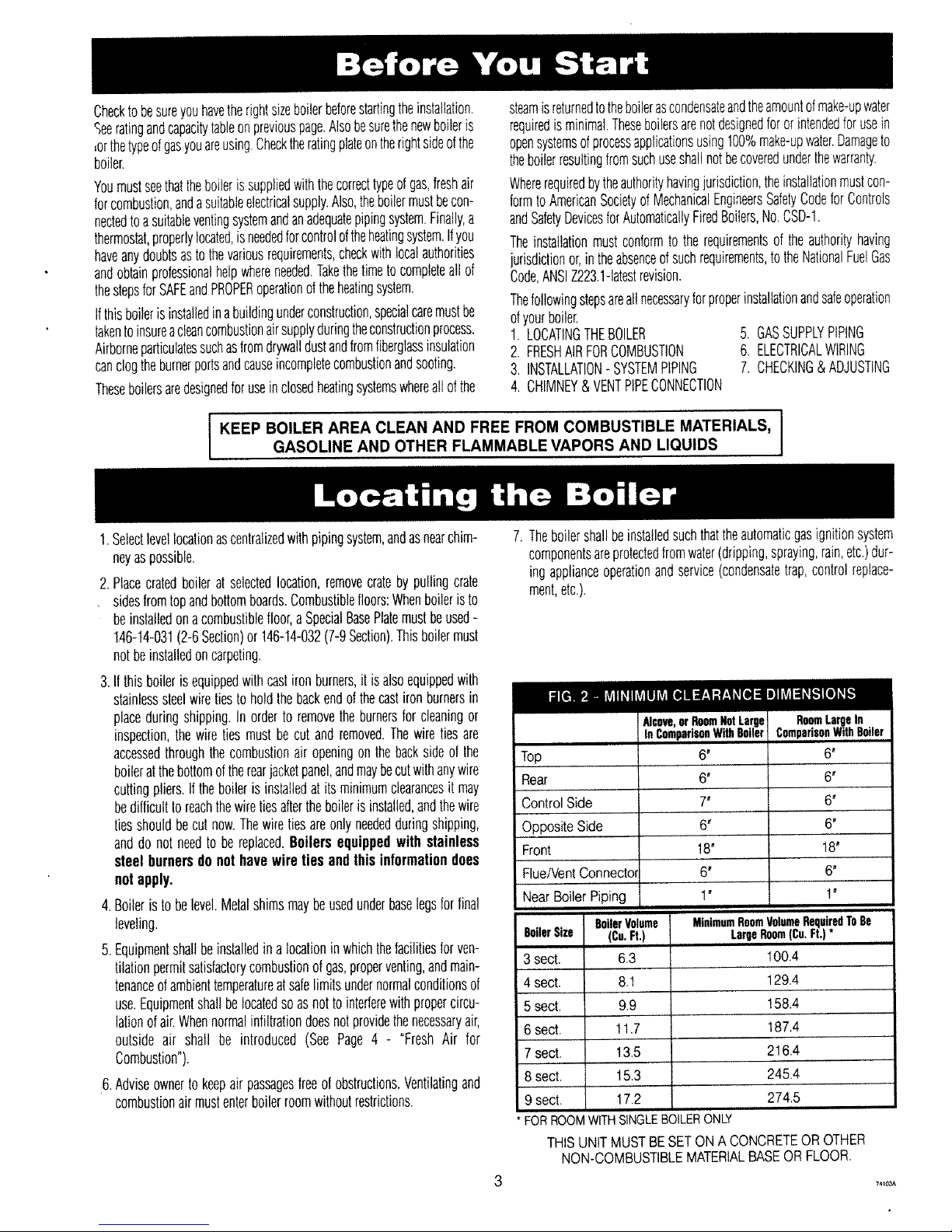
Top
Rear
Control Side
Opposite Side
Front
Flue/Vent Connectol
Near Boiler Piping
BoilerVolume
BoilerSize (Cu.Ft.)
3 sect. 6.3
4 sect. 8,1
5 sect, 9.9
6 sect. 11,7
7 sect. 13.5
8 sect. 15.3
9 sect. 17.2
* FOBROOMWITHSINGLEBOILERONLY
Alcove,orRoomNotLarge
InComparisonWith6oiler
6" 6"
6" 6'
7" 6"
6" 6'
18" 18'
6" 6'
1' 1"
MinimumRoomVolumeRequiredToBe
LargeRoom(Cu.Ft.)*
100.4
129.4
!58.4
187,4
216,4
245,4
274,5
RoomLargeIn
ComparisonWithBoiler
THIS UNIT MUST BESET ON A CONCRETEOR OTHER
NON-COMBUSTIBLEMATERIALBASEOR FLOOR.
?4_oaA
Page 4
Provisionfor combustionandventilationair mustbe in accordancewithSection5.3, Air for CombustionandVentilation,of I
the National Fuel Gas Code, ANSIZ223.1-1atest revision, or applicable provisions of the local building codes.
i
WARNING
Be sure to provide enough fresh air for combustion.
Enough air insures proper combustion and assures that
no hazard will develop due to the lack of oxygen.
NOTE
if you use a fireplace or a kitchen or bathroom exhaust
fan, you should install an outside air intake. These
devices will rob the boiler and water heater of combus-
tion air.
Youmustprovideforenoughfreshairtoassurepropercombustion.Thefire
in theboilerusesoxygen.It musthavea continuoussupply.Theairin a
housecontainsonlyenoughoxygentosupplytheburnerfor ashorttime.
Outsideair mustenterthehouseto replacethatusedbytheburner.Study
followingexamples1and2todetermineyourfreshairrequirements.
EXAMPLE1: BoilerLocatedin UnconfinedSpace
Anunconfinedspaceis definedasa spacewhosevolumeisnotlessthan
50cubicfeetper1,000Btuperhourofthetotalinputratingofallappliances
installedinthatspace.
Ifyourboilerisinanopenarea(unpartitionedbasement)in aconventional
house,theairthatleaksthroughthecracksarounddoorsandwindowswin
usuallybeadequatetoprovideairforcombustion.Thedoorsshouldnotfit
tightly.Donotcaulkthecracksaroundthewindows.
Equipmentlocatedinbuildingsofunusuallytightconstructionshallbepro-
videdwithairforcombustion,ventilation,anddilutionoffluegasesusing
themethodsdescribedinexample2Borshallbespeciallyengineered.The
authorityhavingjurisdictionmustapprovespeciallyengineeredinstalla-
tions.
EXAMPLE2: BoilerLocatedin ConfinedSpace
A.All Air fromInsidethe Building:Theconfinedspaceshallbepro-
videdwithtwopermanentopeningscommunicatingdirectlywithanaddi-
tionalroom(s)of sufficientvolumeso thatthecombinedvolumeof al!
spacesmeetsthecriteriaforanunconfinedspace.Thetotalinputofall
gasutilizationequipmentinstalledinthecombinedspaceshallbecon-
sideredin makingthisdetermination.Eachopeningshallhavea mini-
mumfreeareaofonesquareinchper1,000Btuperhourofthetotalinput
ratingofal!gasutilizationequipmentintheconfinedspace,butnotless
that100squareinches.Oneopeningshallbewithin12inchesofthetop
andonewithin12inchesofthebottomoftheenclosure.Theminimum
dimensionofairopeningsshallnotbetessthan3 inches.
B.AllAirfromOutdoors:Theconfinedspaceshallcommunicatewiththe
outdoorsinaccordancewithmethods1or2.Theminimumdimensionof
airopeningsshallnotbelessthan3 in.Whereductsareused,theyshall
beofthesamecross-sectionalareaasthefreeareaoftheopeningsto
whichtheyconnect.
1.Twopermanentopenings,onecommencingwithin12 inchesofthe
top,andonecommencingwithin12inchesofthebottom,oftheenclo-
sureshallbeprovided.Theopeningsshallcommunicatedirectly,orby
theducts,withtheoutdoorsorspaces(crawlorattic)thatfreelycom-
municatewiththeoutdoors.
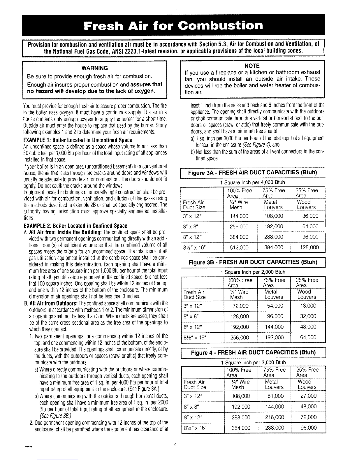
a)Wheredirectlycommunicatingwiththeoutdoorsorwherecommu-
nicatingtotheoutdoorsthroughverticalducts,eachopeningshall
haveaminimumfreeareaof1sq.in.per4000Btuperhouroftotal
inputratingof allequipmentintheenclosure.(SeeFigure3A.)
b)Wherecommunicatingwiththeoutdoorsthroughhorizontalducts,
eachopeningshallhaveaminimumfreeareaof 1sq.in. per2000
Btuperhouroftotalinputratingofallequipmentintheenclosure.
(SeeFigure3B.)
2.Onepermanentopeningcommencingwith12inchesof thetopofthe
enclosure,shallbepermittedwheretheequipmenthasclearanceofat
least1inchfromthesidesandbackand6inchesfromthefrontofthe
appliance.Theopeningshalldirectlycommunicatewiththeoutdoors
orshaltcommunicatethroughaverticalorhorizontalducttotheout-
doorsorspaces(crawlorattic)thatfreelycommunicatewiththeout-
doors,andshallhaveaminimumfreeareaof:
a)1sq.inchper3000Btuperhourofthetotalinputofallequipment
locatedintheenclosure(SeeFigure4),and
b)Notlessthanthesumoftheareasofallventconnectorsinthecon-
finedspace.
1
Figure 3A - FRESH AIR DUCT CAPACITIES (Btuh) I
FreshAir
Duct Size
3"x 12"
8"x 8"
8"x 12"
= 1 tt
18Y2 x 16"
1 Square Inch per 4,000 Btuh
100% Free 75% Free
Area Area
1/4"Wire Metal
Mesh Louvers
144,000 108,000
256,000 192,000
384,000 288,000
5t2,000 384,000
25% Free
Area
Wood
Louvers
36,000
64,000
96,000
128,000
Figure 3B- FRESH AIR DUCT
1SquareInchper2,000Btuh
Fresh Air
Duct Size
3" x 12"
8" x 8"
8" x 12"
81/2"x 16"
100% Free
Area
1/4"Wire
Mesh
72,000
128,000
192,000
256,000
CAPACITIES (Btuh) I
75% Free
Area
Metal
Louvers
54,000
96,000
144,000
192,000
25%Free
Area
Wood
Louvers
18,000
32,000
48,O0O
64,000
Figure 4 - FRESH AIR DUCT CAPACITIES (Btuh)
1Squaretnch per3,000 Btuh
100%Free 75% Free 25% Free
Area Area Area
FreshAir 1/4"Wire Metal Wood
Duct Size Mesh Louvers Louvers
3"x !2" 108,000 81,000 27,000
8"x8" 192,000 144,000 48,000
8"x 12" 288,000 216,000 72,000
8½"x 16" 384,000 288,000 96,000
I
7,_8 4
Page 5
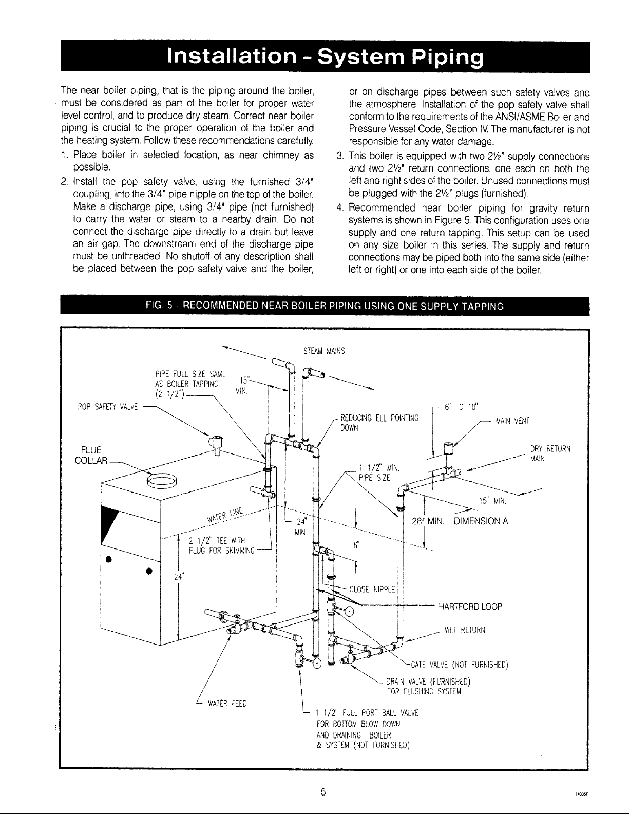
The near boiler piping, that is the piping around the boiler,
must be considered as part of the boiler for proper water
level control, and to produce dry steam. Correct near boiler
piping is crucial to the proper operation of the boiler and
the heating system. Followthese recommendations carefully.
1. Place boiler in selected location, as near chimney as
possible.
2. Install the pop safety valve, using the furnished 3/4"
coupling, intothe 3/4" pipe nipple on the top of the boiler.
Make a discharge pipe, using 3/4' pipe (not furnished}
to carry the water or steam to a nearby drain. Do not
connect the discharge pipe directly to a drain but leave
an air gap. The downstream end of the discharge pipe
must be unthreaded. No shutoff of any description shall
be placed between the pop safety valve and the boiler,
,
,
or on discharge pipes between such safety valves and
the atmosphere. Installation of the pop safety valve shall
conform to the requirements ofthe ANSltASME Boiler and
Pressure Vessel Code, Section IV The manufacturer is not
responsible for any water damage.
This boiler is equipped with two 21/2"supply connections
and two 21/2"return connections, one each on both the
left and right sides ofthe boiler. Unused connections must
be plugged with the 21/2_ plugs (furnished}.
Recommended near boiler piping for gravity return
systems is shown in Figure 5. This configuration uses one
supply and one return tapping. This setup can be used
on any size boiler in this series. The supply and return
connections may be piped both into the same side (either
left or right} or one into each side ofthe boiler.
POPSAFETYVALVE
FLUE
PIPEFULLSIZESAME
AS BOILERTAPPING
(2ii2")_ MIN'
2 1/2" TEEWiTH
PLUGFOR
• 24"
FEED
STEAMMAINS
REDUCINGELL POINTING
DOWN
6" TO 10"
MAINVENT
1 1/2" MtN.
PIPESiZE
NIPPLE
15' MIN,
28' MIN.- DIMENSIONA
I
-- HARTFORD LOOP
WET RETURN
GATEVALVE(NOTFURNISHED)
_"'--DRAiN VALVE(FURNISHED)
FORFLUSHINGSYSTEM
I t/2" FULLPORTBALLVALVE
FORBOTTOMSLOWDOWN
ANDDRAININGBOILER
& SYSTEM(NOT FURNISHED}
DRYRETURN
MAIN
Z4OCBF
Page 6
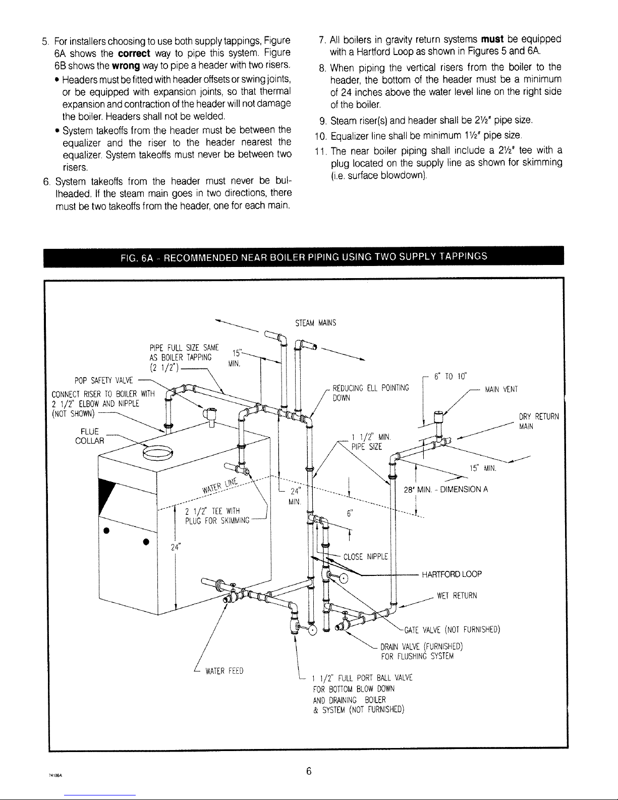
5. For installerschoosing to use both supply tappings, Figure
6A shows the correct way to pipe this system. Figure
6B showsthe wrong way to pipe a header with two risers.
• Headers mustbefittedwithheaderoffsetsorswing joints,
or be equipped with expansion joints, so that thermal
expansion and contraction of the header wilt notdamage
the boiler. Headers shall not be welded.
• System takeoffs from the header must be between the
equalizer and the riser to the header nearest the
equalizer. System takeoffs must never be between two
risers.
6. System takeoffs from the header must never be bul-
lheaded. If the steam main goes in two directions, there
must betwo takeoffsfrom the header, one for each main.
,
8.
All boilers in gravity return systems must be equipped
with a Hartford Loop as shown in Figures 5 and 6A.
When piping the vertical risers from the boiler to the
header, the bottom of the header must be a minimum
of 24 inches above the water level line on the right side
ofthe boiler.
9. Steam riser(s) and header shall be 21/2"pipe size.
!0. Equalizerline shall be minimum 11/2"pipe size.
11. The near boiler piping shall include a 21/2"tee with a
plug located on the supply line as shown for skimming
(i.e.surface blowdown).
PiPEFULL SIZESAME
AS BOILERTAPPING
(2
POPSAFE_ VALVE
CONNECTRISERTO BOILERWITH
2 I/2" ELBOWANDNIPPLE
(NOTSHOWN)
FLUE
COLLAR
MIN,
....{"2112" W TN
PLUGFORS
24"
W_AT_RFEED
STEAMMAINS
REDUCINGELL POINTING
DOWN
6" TO t0"
I1/2" MIN.
PiPEStZE
15" MIN,
28" MIN - DIMENSION A
I
i
NIPPLE
HARTFORDLOOP
RETURN
-GATEVALVE(NOTFURNISHED)
_-- DRAINVALVE(FURNISHED)
FORFLUSHINGSYSTEM
I ;/2" FULLPORTBALLVALVE
FORBOTTOMBLOWDOWN
ANDDRAINING BOILER
& SYSTEM(NOT FURNISHED)
MAINVENT
ORYRETURN
MAiN
_4106A 6
Page 7
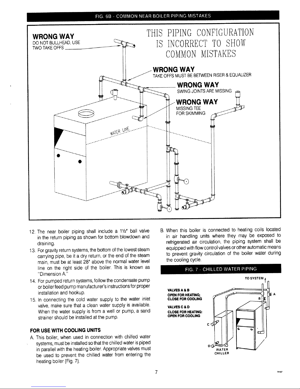
WRONG WAY
DONOTBULLHEAD,USE
TWOTAKEOFFS
THIS PIPING CONFIGURATION
tS INCORRECTTO SHOW
COMMONMISTAKES
WAY
TAKEOFFSMUSTBEBETWEENRISER&EQUALIZER
WRONG WAY
SWINGJOINTSAREMISSING
WRONG WAY
MiSSiNGTEE
FORSKIMMING
12. The near boiler piping shall include a 11h"ball valve
in the return piping as shown for bottom blowdown and
draining.
13. Forgravity returnsystems,the bottom ofthe lowest steam
carrying pipe, be it a dry return, or the end of the steam
main, must be at least 28" above the normal water level
line on the right side of the boiler. This is known as
"Dimension A."
14. For pumped returnsystems,follow the condensate pump
or boiler feed pump manufacturer's instructionsfor proper
installation and hookup.
15. In connecting the cold water supply to the water inlet
valve, make sure that a clean water supply is available.
When the water supply is from a welt or pump, a sand
strainer should be installed at the pump.
FOR USE WITH COOLING UNITS
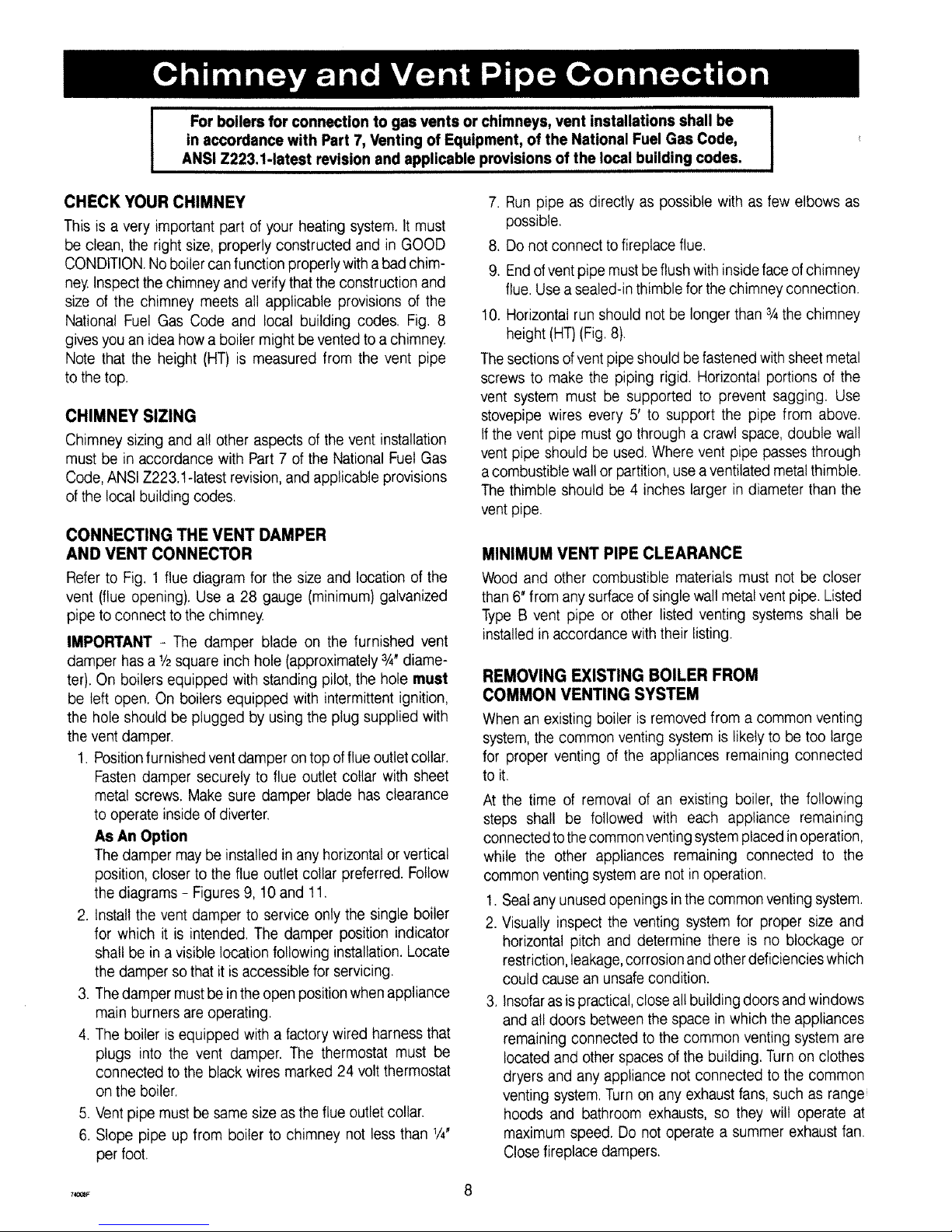
A. This boiler, when used in connection with chilled water
, systems,mustbe installed sothat thechilled water ispiped
in parallel with the heating boiler. Appropriate valves must
be used to prevent the chilled water from entering the
heating boiler (Fig.7).
B When this boiler is connected to heating coils located
in air handling units where they may be exposed to
refrigerated air circulation, the piping system shall be
equipped with flowcontrol valvesor otherautomaticmeans
to prevent gravity circulation of the boiler water during
the cooling cycle.
VALVES A & B
OPEN FOR HEATING;
CLOSE FOR COOLING
VALVES C & O
CLOSE FOR HEATING:
OPEN FOR COOLING
WATER
CHILLER
TO SYSTEM t
74_o7
Page 8
For boilers for connection to gas vents or chimneys, vent installations shall be I
in accordance with Part 7, Venting of Equipment, of the National Fuel Gas Code,
I
ANSI Z223.1-1atest revision and applicable provisions of the local building codes.
CHECK YOUR CHIMNEY
This is a very important part of your heating system. It must
be clean, the right size, properly constructed and in GOOD
CONDITION.Noboilercan function properly with a bad chim-
ney.Inspect the chimney and verify that the construction and
size of the chimney meets all applicable provisions of the
National Fuel Gas Code and local building codes. Fig. 8
gives you an idea how a boiler might be vented to a chimney.
Note that the height (HT} is measured from the vent pipe
to the top.
CHIMNEY SIZING
Chimney sizing and all other aspects of the vent installation
must be in accordance with Part 7 of the National Fuel Gas
Code, ANSI Z223.1-latest revision, and applicable provisions
ofthe local building codes.
CONNECTING THE VENT DAMPER
AND VENT CONNECTOR
Refer to Fig. 1 flue diagram for the size and location of the
vent (flue opening). Use a 28 gauge (minimum) galvanized
pipe to connect to the chimney.
IMPORTANT - The damper blade on the furnished vent
damper has a 1/2square inch hole (approximately 3/4"diame-
ter). On boilers equipped with standing pilot, the hole must
be left open. On boilers equipped with intermittent ignition,
the hole should be plugged by using the plug supplied with
the ventdamper.
1. Positionfurnished vent damper on top offlue outletcollar.
Fasten damper securely to flue outlet collar with sheet
metal screws, Make sure damper blade has clearance
to operate inside ofdiverter.
As An Option
The damper maybe installed in any horizontal or vertical
position, closer to the flue outlet collar preferred. Follow
the diagrams - Figures 9, 10 and 11.
2. Install the vent damper to service only the single boiler
for which it is intended. The damper position indicator
shall be in avisible location following installation. Locate
the damper so thatit is accessible for servicing.
3. Thedamper mustbeintheopen position whenappliance
main burners are operating.
4. The boiler is equipped with a factory wired harness that
plugs into the vent damper. The thermostat must be
connected to the black wires marked 24 volt thermostat
on the boiler.
5. Vent pipe must be same size as the flue outlet collar.
6. Slope pipe up from boiler to chimney not less than 1/4'
per foot.
7. Run pipe as directly as possible with as few elbows as
possible.
8. Do not connect tofireplace flue.
9. Endofvent pipe must be flush with insideface ofchimney
flue. Usea sealed-in thimblefor the chimney connection.
10. Horizontal run should not be longer than 3/4the chimney
height (HT}(Fig.8}.
The sectionsofventpipeshould be fastenedwith sheet metal
screws to make the piping rigid. Horizontal portions of the
vent system must be supported to prevent sagging. Use
stovepipe wires every 5' to support the pipe from above.
If the vent pipe must go through a crawl space, double wall
vent pipe should be used. Where vent pipe passes through
a combustible wall or partition, use a ventilatedmetal thimble.
The thimble should be 4 inches larger in diameter than the
vent pipe.
MINIMUM VENT PIPE CLEARANCE
Wood and other combustible materials must not be closer
than 6" from anysurfaceof single wall metal vent pipe. Listed
Type B vent pipe or other listed venting systems shall be
installed in accordance with their listing.
REMOVING EXISTING BOILER FROM
COMMON VENTING SYSTEM
When an existing boiler is removed from a common venting
system, the common venting system is likely to be too large
for proper venting of the appliances remaining connected
to it.
At the time of removal of an existing boiler, the following
steps shall be followed with each appliance remaining
connectedto the commonventingsystemplaced inoperation,
while the other appliances remaining connected to the
common venting systemare not in operation.
1. Sealany unused openings in the common venting system.
2. Visually inspect the venting system for proper size and
horizontal pitch and determine there is no blockage or
restriction,leakage,corrosionand otherdeficiencies which
could cause an unsafecondition.
3. Insofaras is practical,close all building doors and windows
and atl doors between the space in which the appliances
remaining connected to the common venting system are
located and other spaces of the building. Turnon clothes
dryers and any appliance not connected to the common
venting system. Turn on any exhaust fans, such as range
hoods and bathroom exhausts, so they will operate at
maximum speed. Do not operate a summer exhaust fan.
Close fireplace dampers.
7_ 8
Page 9
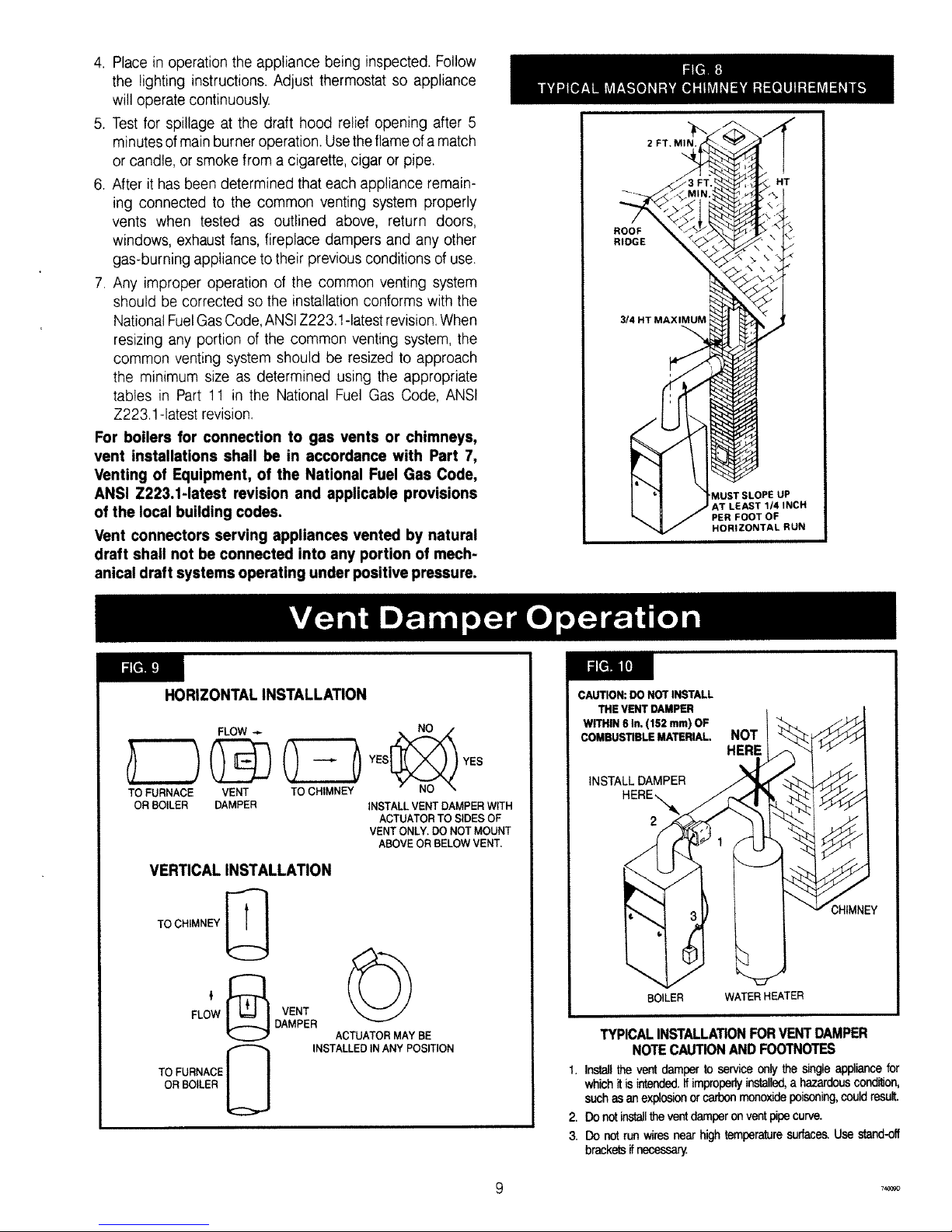
4. Place in operation the appliance being inspected. Follow
the lighting instructions. Adjust thermostat so appliance
will operate continuously.
5. Test for spillage at the draft hood relief opening after 5
minutesofmain burner operation. Usetheflameofamatch
or candle, or smoke from a cigarette, cigar or pipe.
6. After it has been determined that each appliance remain-
ing connected to the common venting system properly
vents when tested as outlined above, return doors,
windows, exhaust fans, fireplace dampers and any other
gas-burning appliance to their previous conditions of use.
7. Any improper operation of the common venting system
should be corrected so the installation conforms with the
National FuelGasCode,ANSIZ223.1-latestrevision. When
resizing any portion of the common venting system, the
common venting system should be resized to approach
the minimum size as determined using the appropriate
tables in Part 1! in the National Fuel Gas Code, ANSI
Z223.1 -latestrevision.
For boilers for connection to gas vents or chimneys,
vent installations shall be in accordance with Part 7,
Venting of Equipment, of the National Fuel Gas Code,
ANSI Z223.1-1atest revision and applicable provisions
of the local building codes.
Vent connectors serving appliances vented by natural
draft shall not be connected into any portion of mech-
anical draft systems operating under positive pressure.
ROOF
RIDGE
3t4 HT MAXIMUM
J
MUST SLOPE UP
AT LEAST 1/4 INCH
PER FOOT OF
HORIZONTAL RUN
HORIZONTAL INSTALLATION
YES YES
TO FURNACE VENT TO CHIMNEY
OR BOILER DAMPER INSTALL VENT DAMPER WITH
ACTUATOR TO SIDES OF
VENT ONLY, DO NOT MOUNT
ABOVE OR BELOW VENT,
VERTICAL INSTALLATION
TO CHIMNEY
€ _ VENT
FLOW uDAMPE R
TO FURNACE N
OR BOILER U
ACTUATOR MAY BE
INSTALLED IN ANY POSITION
CAUTION: DO NOT INSTALL
THE VENT DAMPER
WITHIN 6 In. (152 ram) OF
COMBUSTIBLE MATERIAL.
INSTALL DAMPER
NOT
HERE
_'HtMNEY
BOILER WATER HEATER
TYPICAL INSTALLATION FOR VENT DAMPER
NOTE CAUTION AND FOOTNOTES
1. Install the vent damper to service only the singleappliance for
which it is intended.Ifimproperly installed,a hazardous condition,
such as an explosion or carbon monoxidepoisoning,could result.
2. Do not installthevent damper on vent pipecurve.
3. Do not run wires near high temperature surfaces. Use stand-off
brackets ifnecessary.
7_c090
Page 10

For safe, efficient operation, the vent damper and all flue
product carrying areas of the appliance must be checked
annually byyou, with particular attention given to deterioration
from corrosion or other sources. If you see corrosion or other
deterioration,contactyour heating contractorfor repairs. Check
vent damper operation as follows:
1. When theboilerisoff,check thattheventdamperpositions
indicator points to theclosed position, Fig. 11.
2. Turn the thermostat or controller up to call for heat and
check the vent damper indicator points to the open
position, Fig. 11.
3. Turn the thermostat or controller down again and check
that the damper position indicator returns to the closed
position.
4. If you have central air conditioning, set the thermostat
to COOL and turn it down to call for cooling. Cooling
system should operate.
5. Return thermostat to desired position.
The vent damper must be inspected at least once a year
by a trained, experienced service technician. The name
ofthe person who originally installed your vent damper is
shown on the installation label.
MANUAL OPERATION OF THE VENT DAMPER
The ventdamper may be placed in the open position to permit
burner operation by usingthe "HOLD DAMPER OPEN" switch,
located on the damper controller. The thermostat will control
the burnerfiring as before, whilethe damper will remain open.
DO NOT turn damper open manually or motor damage will
result. Set switchto "AUTOMATIC OPERATION" to close vent
damper during burner off cycle.
Forfurther information, and for a vent damper troubleshooting
guide, refer to the manual that was packaged with the vent
damper.
z
DAMPER CLOSED DAMPER DPEN
SHOWING OPEN AND CLOSED POSITION
CHECK GAS SUPPLY
The gas pipe to your boiler must be the correct size for the
length of the run and for the BTU per hour input of all gas
utilizationequipment connected to it. See Fig. 12for the proper
size. Besure your gas line complies with local codes and gas
company requirements.
The boilerand its individualshut-off valve must bedisconnected
from the gas supply piping system during any pressure testing
of that system attest pressures inexcess of ½ psig (3.5 kPa).
This boiler must be isolated from the gas supply piping system
by closing its individual manual shut-off valve during any
pressure testing of the gas supply piping system at test
pressures equal to or tessthan ½ psig (3.5 kPa).
CONNECTING THE GAS PIPING
Refer to Fig. 13 for the general layout at the boiler. It shows
the basic fittings you will need. The gas line enters the boiler
from the right side.
The following rules apply:
1. Use only those piping materials and joining methods
listed as acceptable bythe authority havingjurisdiction,
or in the absence of such requirements, by the National
Fuel Gas Code, ANSI Z223.1-1atestrevision.
2. Use pipe joint compound suitable for LP gas on male
threads only.
3. Use ground joint unions.
4. Install a sediment trap upstream of gas controls.
5. Use two pipe wrenches when making the connection to
the gas valve to keep it from turning.
6. Install a manual shut-off valve in vertical pipe about 5
feet above floor.
7. Tighten all joints securely.
8. Propane - gas connections should only be made by a
licensed propane installer.
9. Two-stage regulation should be used by the propane
installer.
10. Propane - gas piping should be checked out by the
propane installer.
CHECKING THE GAS PIPING
Upon completion of piping, check immediately for gas leaks.
Open the manual shut-off valve. Test for leaks by applying
soap suds (ora liquiddetergent) to eachjoint. Bubblesforming
indicate a leak. CORRECT EVENTHE SMALLEST LEAKAT
ONCE.
I WARNING I
Never use a match or open flame to test for leaks
10
Page 11

Length of
Pipe - Ft.
2O
4O
60
NATURAL GAS
Pipe Capacity - BTU Per Hour Input
includes Fittings
Y2" 314" 1"
92,000 190,000 350,000
63,000 130,000 245,000
50,000 105,000 195,000
1¼"
625,000
445,000
365,000
Length of
Pipe- Ft.
20
40
60
PROPANE GAS
Pipe Capacity - BTU Per Hour input
includes Fittings
CopperTubing*
%- ¾-
131,000 2!6,000
90,000 145,000
72,000 121,000
Iron Pipe
½- ¾-
189,000 393,000
129,000 267,000
103,000 217,000
*Outside diameter
The length of pipe or tubing should be measured from the gas meter or propane
second stage regulator.
VALVE
iZT'" tl
\ o=oLL
FLOOR SEDIMENT TRAP
LINE ........."___
ELECTRIC POWER SUPPLY
All electrical work must conform to local codes, as wel! as
the National Electrical Code, ANSt/NFPA-70, latest revision.
Run a separate 120 volt circuit from a separate overcurrent
protective device in your electrical service entrance panel.
This should be a 15 ampere circuit. Locate a shut-off switch
at the boiler. It must be turned off during any maintenance.
Connect 120 volt electrical supply to the primary leads on
the 24 volt transformer. Solder and tape or securely fasten
these connections with wire nuts.
The boiler, when installed, must be electrically grounded in
accordance with the requirements of the authority having
jurisdiction or, in the absence of such requirements, with the
National Electrical Code, ANSI/NFPA No. 70-latest revision.
Run a 14 gauge or heavier copper wire from the boiler to
a grounded connection in the service panel or a properly
driven and electrically grounded ground rod.
WARNING
Turn off electric power at fuse box before making any
line voltage connections. Follow local electrical codes.
INSTALL YOUR THERMOSTAT
The thermostat location has an important effect on the
operation of your boiler system. BE SURETO FOLLOW THE
INSTRUCTIONSINCLUDEDWITHYOURTHERMOSTAT,
Locate the thermostat about five feet above the floor on an
inside wall. It may be mounted directly on the wall or on
a vertically mounted outlet box. It should be sensing average
room temperature, so avoidthe following:
DEAD SPOTS:
Behind doors
Corners and alcoves
HOTSPOTS:
Concealed pipes
Fireplace
TVsets
Radios
Lamps
Direct sunlight
Kitchens
COLD SPOTS:
Concealed pipes or ducts
Stairwells - drafts
Doors - drafts
Unheated rooms on other side of wall
Set heat anticipator at 0.4 amps for boilers equipped with
standing pilot, and at 0.6 amps for boilers equipped with
intermittent ignition. The 24 volt thermostat leads shall be
connected to the two wires tagged "24 volt thermostat" on
the boiler. For boilers with 67D-1 float type tow water cut-
off, the two wires are black. One wire is located on the
secondary of the 24 volt transformer, the second wire is
located on the pressure limit control. For boilers with PS-
802 probe type low water cut-off, one wire is green and
is located on terminal B of the PS-802, the second wire is
black and located on the pressure limit control.
ELECTRONIC THERMOSTATS
Certaintypes ofelectronic thermostatsmay losetheirmemory
or shut down. With 67D-1 float type low water cut offs,
this may occur each time the thermostat calls for heat,
due to the internal circuit in the vent damper. With PS-802
t 74o11F
Page 12

probe type low water cut offs, this may occur each time the
low water cut off detects a low water condition. If this is the
case, an isolation relay is required for the thermostat circuit.
A 24 volt single pole single throw (SPST)normally open (NO)
relay is required, such as the Honeywell R8222A or
equivalent. Wire as shown in Fig. 14A or Fig. 14B.
VENT DAMPER
The boiler is equipped with a factory wired harness with 4
pin molex plug, that plugs into the 4 pin molex receptacle
inside the vent damper operator.
Theventdamper must beconnected for theboiler to operate.
Wiring diagrams follow for the various different models.
CAUTION
Label all wires prior to disconnection when
servicing controls. Wiring errors can cause
improper and dangerous operation. Verify proper
operation after servicing.
VENT DAMPER
4 PIN
24 VOLT
TRANSFORMER
T "_\_ ELECTRONIC
TO LWCO AND THERMOSTAT
IGNITION SYSTEM
..... FIELD WIRING
VENT DAMPER
4 PIN
MOLEX PLUG
__y _ ISOLATION RELAY 24V.
\SPST N,O, HONEYWELL
I J \R8222A OR EQUIVALENT
\
24 VOLT IIF .... _::__ -K---_ -_0
TRANSFORMER !m Z-IPRESSURELIMIT
wBT, Ti
I / _t" _"'--_ TERMINAL B
/ _- c<o--- G OF LWCO
1 _- ELECTRONIC
TO WCO AND THERMOSTAT
IGNITION SYSTEM --- FIELD WIRING
..... 12
Page 13

i
15 7/i OH2,/I _ i
PO¢,'E_ BK
SUPPL
NEUT --
ov'£ cI R NI P_O EC]£
{}15C NNEC
i / ......
',(}} .£................
OPI_O_',A[ WF 2U 24
F EX:::t
NOTE:TE2MN-_ NO "_ Af'r;r'hR_: ONY
)ld V'AIq r< Ir_ED[_ MOIIt[5 WrH
M/,N'JAL F_ED PUSH BUWON
INTERMITTENT IGNITION
vl[iqT DAMPER
M©LEX PLUG
i
<:'i >i
_, ] o '
i ............ ] o
.... i ,. t _K
L _...................
Y
_4 I(X ! CON/4!:(: Ol_
//
\N
SHUTOFF
BL)CKED 4ENT li_L
SAFEF!'
SHIJTOF_ ¸
15V/6OHZi i ¢,
OVERCIJRREN] PROIEC] ED
/;ISC()NNECT
JT 1OO3-620 SERIES
_TERMI_TENT PLOT CONTROL
..... _: ]
O_ERAHO/_ / HOLD DAMPER OPEN W CI4 i ::: ©ND
J
IF ANY OF THE ORIGINAL WIRE AS SUPPLIED WITH THIS APPLIANCE MUST BE REPLACED,
IT MUST BE REPLACED WITH TYPE 105°C THERMOPLASTIC WIRE OR ITS EQUIVALENT.
13
Page 14

STANDING PILOT
Will lAMP R
M(L {7, 'L U(
f: :77: .....
i ( ) /} t) t_}
NEU/ i I _
• "?'7" ...... .......
r j ) k i i i ']' i LJ] Orl
f +7 ............................................................................g 1 r' kfls: , !
t,;:i .................................i................................................................[ii_'
W/-TER
F£E[,_:R
rqol[:
rER_AL NO_ 5 APPEAR_o ONP,"
ON WAr_R FEEr,ER MOOEP, WI01
M.tr_A} v_r) Pu%H BUmrOq
WIRE }_UT
COLOR C3:,E
_R BROWN
O OP.AN{SE
BI¸ 8'_,_7d WiTH IAAO_R
_Si:7 (_s7
{W
i i
i ..... 7:: .........................
Tr_
, {>
i }
;AFE[ f HUT)Fr I'
H
vJLO i O ,i!l
"D]: : " HU i)f:
/oooo-4 POI E CON'\lICTOR
/
/ _......................................VENT DAMPER CA[7_ E
//
/
/
\
T}
VENT <"
DAMPER
/
\
,!,., I <w,_/<"
£2 TFWRMO TAT
i " ' - W /
i "
_ II _F_ I
i
:_/-=:),i i_K
OVERCURREN I
PAOT CTED
GA*g Ol COHNFCI
VA_ _
NOTE:
SIA AND S1B ARE TtE AUIOMAIC OPERA-ION / itO/D DAMPER OPEN >W!TCH
SWICI SIOWN N AUrOMA C POS11ON,
$2, $5, AND £4 ARF CAM ACTUATED SNAP SYqTC i8S
1i }V!60 t !//¢
IF ANY OF THE ORIGINAL WIRE AS SUPPLIED WITH THIS APPLIANCE MUST BE REPLACED,
IT MUST BE REPLACED WITH TYPE 105°C THERMOPLASTIC WIRE OR ITS EQUIVALENT.
14
Page 15

2¢ VOLT
TRANSFORMER --_
N
11 S///6OHZ/1 ¢
POWER SUPPLY
HOT ----._
OVERCDRRENT PROTECTED
DISCONNECT
W
NEUT
VENT DAMPER
MOLEX PLUG
Y
INTERMITTENT IGNITION
THEI44r)gT4]'
__4//
P RESSLIRE LIMIT
OPTIONAL WF-2U-24
WATER FEEDER
NOTE:
TERMINAL NO. 5 APPEARS ONLY
ON WATER FEEDER b4ODELS WITH
MANUAL FEED PU£H BUTTON
I'
BK
LOW WATER
OUT OFF
BK
FbkblE ROLLOUT
SAFETY SHUTOFF
_i--W_RE NUT
COLOR CODE
BK--BLACK
BR-BROWN
0 -ORANGE
Y -YELLOW
R -RED
BT-BLACK WiTH TRACER
W -WHITE
G -GREEN
UT 1003-620 SERES
NTERt,4[TTENT PILO'TCONTROL
" 4 POLE CONFECTOR
/
j/"
'\
THERMOSTAT
_o_i Io¸ _Z
H_SSURE
i_qT
/ BKi
PI-04I i j 24- V
j SECONDAR f
I y i BK
t..............................I . i
\x o9 i
I_/! LiT fOG3 620 SERIEb '_
I I
/
I
l
7 A_,_m ROL' O [ ffTERbdll] NI PI O1 CONTROL F. (J 7AI
SARET¢ ",, F ] l _ _._- Ho
_H iTCFF < ) - i I
{7OL! ED vE _ _ _
SHt TOFF / _IGI/wl IBK r i_,_,KB[ [O FlOg [} JR'/ R
NO/: J _ i J pK
M/M........................,
OPERATION / HOD DAMPER OPEN SWITCI i I _._i i_c/il) I#s/
SW_TCH SHOWN IN AUTOMATC POSTIO"/ l iNi2 pv / GAS VAVE
S2 $3 AND $4 ARE CAM ACLAi D SNAP SWfC4ES _ PV/MV VR8204A / 'vR:_3OaM
/ 15V!601 'Z,//¢
IF ANY OF THE ORIGINAL WIRE AS SUPPLIED WITH THIS APPLIANCE MUST BE REPLACED,
IT MUST BE REPLACED WITH TYPE 105°C THERMOPLASTIC WIRE OR ITS EQUIVALENT.
15
Page 16

24 _OL1
TRAHSFORMER _\
" Bi<
1 15Vi@HZ/1 r,_ '\,
\
POWER SUPPM
lOT
OVER( U RI:_E'\! PROYEC El
01SCOk qECT
W
NEUT
I,lO :
fERb'INA NO 3 APPEARS Ob_ Y
ON WATER FEEDER MODEl> WiTII
MANbAt FEE{) PUSH BtlTION
VE:i\I7 )/¢4 Y'{ I:,
I/0i E:X /:i tJ(,
STANDING PILOT
PRES _URE /IMIi
1,
BK
WiRE NUT
COLOR CODE
BK BLACK
BR BROW!N
0 Or#Ai,,OE
Y YELOW
_< Ik<ED
BT B_ACK WFH TRACER
W WIE
O GREEN
FLAME ROILOLIT BLOCKED VENT
.<;AFE]Y SHUF)F: SAFELY SHU OSF
, +i PX)L[ COl N(:(:} OR
/
//
i /
TO /_
'/Nl <"
I)/kIP R
PI 02i I0 I _ THFRMOSTAT
PRESSt.iR£
NOTE:
i} SIA AND SI[J ARE THE AU}OM£]IC
Ol EI_£10N / I/(}LI3 DAMPER OPEN SWFCI_
_Wi[C/i Siq©WN IN A_f[(>MATiC POSIHON
$2, $3, AND $4- ARE CAM A¢_UAilED SI/AP SWI/CHES
OVERCIiRRE} T
PROTECED
DIS/,: ( N qEC i
1 / 5V/ iO Ei'I ¢
IF ANY OF THE ORIGINAL WIRE AS SUPPLIED WITH THIS APPLIANCE MUST BE REPLACED,
IT MUST BE REPLACED WITH TYPE 105°C THERMOPLASTIC WIRE OR ITS EQUIVALENT.
16
Page 17

POP SAFETY VALVE
The pop safetyvalve should open automatically if the boiler
steam pressure exceeds the pressure rating ofthe valve (15
psig). Should it ever fail to open under this condition, shut
down your boiler. If valve discharge occurs, or valve fails
to open asdescribed above, contact an authorizedcontractor
or qualified service technician to replacethe pop safety valve
and inspect the heating system to determine the cause, as
this may indicate an equipment malfunction.
Run a pipe from the safety valve outlet (pipe must be same
size as outlet and open end must not be threaded) to an
open drain, tub or sink, or other suitable drainage point not
subject to freezing. Failuretodo so maycausewater damage
or injury should relief valverelease. Do not cap off the drain
line from this valve!
STEAM PRESSURE GAUGE
Every system should havea pressure gauge installed in the
boiler. This gauge enables you to monitor the pressure in
the system. If the safety devices fail to shut off your boiler
atthe proper settings,notify your serviceman immediately.
WATER LEVEL GAUGE
The water level in the boiler can be seen through the glass
tube in the water level gauge at side of boiler. Correct cold
boiler water level isstamped on side jacket panel. The water
level should be checked regularly for the proper level.
On the right side jacket panel of the boiler, there are three
holesforthe glass water level gauge.Thetop hole is common
for both types of low water cut off, and is used for the upper
gauge glass fitting. The middle hole, 9" down from the top
hole, is used for the bottom gauge glass fitting for the Model
67D-1 and 47-2 float type low water cut off.The lowest hole,
12¼_down from the top hole, is used for the bottom gauge
glass fitting for the Model PS-802 probe type low water cut
off. The hole that is not being used is covered with a sheet
metal knockout.
STEAM PRESSURE CONTROL
The steam pressure limit control (pressuretrol)shuts off the
gas to the main burners when the steam pressure in the
boiler reaches the cut-off setpoint (i.e. the sum of the cut-
inand thedifferentialsetpoints).Burnersretirewhen the steam
pressure drops to the cut-in setpoint. System pressure
requirements are based on the size and condition of the
pipes, and the load.
LOW WATER CUT-OFF
1. Model 67D-1
This isa float operated switch which shuts down the gas
burner if waterfalls below the visible bottom of the gauge
glass.
2. Model PS.802
This is an electronic probe type LWCO.The probe is
located inside the boiler. The LWCOwill shut down the
burners if the water loses contact with the probe for a
period of 10 seconds.
Refer to manufacturer's instructions (enclosed) for more
information.
WATER FEEDER (Optional)
TheModel WF-2U-24water feeder maybe used with either
of the available low water cut-offs. The water feeder's job
is to maintain a safe minimum water level. It's used to
keep the boiler running by compensating for minor
evaporative steam leaks,and to prevent freeze-ups if the
homeowners are away and a return line should spring
a leak.
McDonnell and Miller Model 10t water feeders may be
used, howeverthe water feed ratesare too high and need
to be regulated or throttled, and wiring will have to be
revised.Consultthe boiler manufacturerbefore usingthese
or any other non-standard types of controls.
The automatic water feeder is a safety device, not a
convenience item.Itisnotdesigned to maintaina "normal"
water line. The water feeder does not take the place of
a responsible person monitoring and maintaining the
normalwaterline.Steam boilers require personal attention.
VENT DAMPER
This is an automatic, motorized stack damper that has
been developed to increase the efficiency of heating
systems by reducing standby losses from the boiler and
the conditioned air space.The damper closes thechimney
vent when the burner is off and fully opens it when
combustion is required.
ROLLOUT SWITCH
(FLAME ROLLOUT SAFETY SHUTOFF)
The rollout switch is a temperature-sensitive fuse link
device. It is located on the boiler base just outside the
fire box. In the event of heat exchanger flueway blockage
causing flame to roll out of the fire box, the fuse will blow,
shutting down the flow of gas to the main burners. The
fuse does not change in appearance when blown.
If the ro!!out switch blows, it must be replaced with an
exact replacement. Check heat exchanger flueways for
blockage when restoring system to operating condition.
Donot operate system without a rollout switch.
SPILL SWITCH
(BLOCKED VENT SAFETY SHUTOFF)
The spil! switch is a manual reset disc thermostat with
a fixed setpoint (280° F}, and normally closed contacts.
It is located at the relief opening of the draft diverter. In
the event of chimney or venting system blockage causing
products of combustion to spill out of the relief opening,
the spill switch disc heats up and the spill switch contacts
willopen, shuttingdown theflow ofgas tothe main burners
by removing power to the gas valve.
In the event that the spill switch contacts open, the reset
button on the back of the switch will pop up. The spill
switch must be reset manually,after theswitch hascooled
off, by pushing the reset button down. Check the venting
system and chimney for blockage when restoring the
system to operating condition. DO NOT operate the boiler
without a spill switch.
7 74_
Page 18

WARNING: If you do not follow these instructions exactly, a fire or explosion
may result causing property damage, personal injury or loss of life.
A. Some boilers are equipped with an intermittent ignition
device which automatically lights the pilot. Do not try to
light the pilot by hand.
Some boilers are equipped with a continuous pilot and
must bemanuallylighted. (Seelighting instructionson page
18-19.) A match holder is included in the parts bag.
B. BEFOREOPERATINGsmell all around the appliance area
for gas. Be sure to smell next to the floor because some
gas is heavierthan air and will settle on the floor.
WHATTO DO IFYOUSMELLGAS
• Do nottry to light any appliance,
• Do not touch any electric switch; do not use any phone
in your building.
C.
U.
• Immediately call your gas supplier from a neighbor's
phone. Followthe gas supplier's instructions.
elf you cannot reach your gas supplier, call the fire
department.
Use only your hand to push in or turn the gas control
knob. Never use tools, tf the knob will not push in or turn
by hand, don't try to repair it, call a qualified service
technician. Force or attempted repair may result in a fire
or explosion.
Do not use this appliance if any part has been under
water. Immediately call a qualified service technician to
inspect theappliance and toreplace any partofthecontrol
system and any gas control which has been under water.
1. STOP!Readthe safety information on this page.
2. Set the thermostat to lowest setting.
3. Turn off all electric power to the appliance.
4. This appliance isequipped withan ignition device which
automatically lights the pilot. Do not try to light the pilot
by hand,
aB
GAS _,INLET
GAS CONTROL KNOB
SHOWN IN "ON" POSITION
5. Remove lower front panel.
6. Rotate the gas control knob clockwise _ to"OFE"
7. Wait five (5) minutes to clear out any gas. Then smell
for gas, including near the floor. If you smell gas, STOP!
Follow "B" in the safety information on this page. If you
don't smell gas, go to next step.
Rotatethe gascontrolknob counterclockwise If to"ON."
Replace lowerfront panel.
Turn on all electric power to the appliance.
Setthermostat to desired setting.
If the appliance wilt not operate, follow the instructions
"To Turn Off Gas To Appliance" and call your service
technician or gas supplier.
TURN OFF GAS TO APPLIANCE
1_Set the thermostat to lowest setting.
2. Turn off all electric power to the appliance if service is
to be performed.
3. Push in gas control knob slightly and turn clockwise
to "OFE" Do notforce.
,
9.
10.
11.
12.
TO
..... 18
Page 19

1.STOP!Readthesafetyinformationonpage18.
2.Setthethermostattolowestsetting.
3.Turnoffallelectricpowertotheappliance.
4.Removelowerfrontpanel.
5.Rotategascontrolknobslightlyandturnclockwise
GAS CONTROL KNOB
to "OFE" F SHOWNIN''ON"POSIT!ON
GAS
INLET
• o
RESET BUTTON
6. Wait five (5) minutes to clear out any gas. Then smell
for gas, including near the floor. If you smell gas, STOP!
Follow "B" in the safety information on page 18. If you
don't smell gas, go to next step.
7. Find pilot - follow metal tube from gas control. The pilot
is betweentwo burner tubes as shown in Fig. 15.
8. Turn knob on gas control counterclockwise _ to
"PILOT."
9. Rotate the gas control knob counterclockwise i_ to
"PILOT."Pushdown and hold the red reset button while
you light pilot burner with a match.
After about one minute, releasereset button.Pilotshould
remain lit. If it goes out, turn gas control knob clockwise
'W to OFF Torelight, repeat steps 5-9.
* If button does not pop up when released, stop and
immediately callyourservice technicianorgassupplier.
* If the pilot will not stay lit after several tries, turn the
gas control knob to "OFF" and call your service
technician or gas supplier.
10. After pilot remains lit when red reset button is released,
turn gas control knob counterclockwise t_ to "ON."
11. Replace lowerfront panel.
!2. Turnon all electric power to the appliance.
13. Set thermostat to desired setting.
TO TURN OFF GAS TO APPLIANCE
1. Set the thermostatto lowestsetting.
2. Turn off all electric power to the appliance if service is
to be performed.
3. Push in gas control knob slightly and turn clockwise
_i to "OFF" Do not force.
i_ATCH HOLDER
PRESSURE REGULATOR CONVENIENCE WIRING
ADJUSTMENT TERMINALS(2} /TERMINALS (2)
(UNDER CAP SCREW)*, (OPTIONAL) | / OUTLET PRESSURE
PRESSURE TAP
THERMOCOUPLB PILOT ADJUSTMENT
CONNECTION .B/ \RR[_ET _GAS (UNDER CAP SCREW}
BU'i'FON CONTROL/VALVE
1L62aA KNOB
PRESSURE REGULATOR
ADJUSTMENT
(UNDER CAPSCREW
INLET _
PRESSURETA
IZ.160
WIRING
TERMtNALS(3)
OUTLETPRE$SURE
,,, TAP
GROUND
n TERMINALS(2)
1_ OUTLET
._PILOT OUTLET
_PILOT ADJUSTMENT
(UNDER CAPSEREW)
_GA$
CONTROL
KNOB
1 g 7_o17J
Page 20

HOW A STEAM SYSTEM OPERATES
The water in the boiler is heated until it reaches the boiling
point. As the water boils it turns into steam.The steam rises
from the top of the water through the supply main to the
radiation units. As it passesthrough the radiators it releases
its heat and condenses into water. The water returns to the
boiler through the return main. Most residential systems
operate at less than 1 pound steam pressure.
FILLING SYSTEM WITH WATER
On steam heating systems the boiler is partially filled with
water.Itis very importantto the proper operation of the entire
system thatyour boilerbe filled tothe proper level.The correct
water level is about halfway up the glass water level gauge
as marked on the boiler jacket. Tofill:
1. Close the boiler drain valve.
2. Open the valvesat the top and bottom of the glass water
level gauge. Also open the drain valve at the bottom of
the gauge.
3, Open the fill valve and allow waterto run into the boiler.
WARNING - Neverrun waterintoa hotemptyboiler. I
4. Allow boiler to fill until water runs out the gauge drain
valve.Then close the gauge drain valve.
5. Continuetofill boiler until water reachesthe indicated water
line. This isabout halfwayup the glasstube.
WATER LEVEL
The normal water level is shown on the right side of the
boiler and is 24" above the floor. The normal water level
is determined when the boiler is off and cold, i.e. when all
of the water in the system is inside the boiler and the return
piping below the water line, and everything above the water
line is air, no steam. When the boiler is making steam, the
water level will drop two to three inches below the normal
water line.
AUTOMATIC GAS VALVE
The Automatic Gas Valve opens or closes according to the
heat requirements of the thermostat and temperature limit
control. It closes ifthe pilot goes out. Each individual control
must be operating correctly before any gas can pass to the
burners. Any one control can hold the gassupply from burner
regardless ofthe demand of any other control.
THERMOSTAT
Keep it set at a desired room temperature. If windows are
to beopened or heatis not needed, move thermostat pointer
to alower setting.
NOTE
In the event of failure of any component, the system
will not operate or will go intosafetylockout. Thesystem
iscompletely self-checking. On every callfor heat, each
component must be functioning properly to permit
operation. On safety lockout the system has to be reset
by turning the thermostat to the lowest setting for one
minute,then back tothe normal setting.
Safe lighting and other performance criteria were met with
the gasmanifold and control assembly provided on the boiler
when the boiler underwent tests specified in ANSI Z21.13
- latestrevision.
...... 20
Page 21

ADJUST PILOT BURNER
Pilotflameshouldsurround3/8" to 1/2" ofthepilot sensor.Refer
to Fig.19.Ifflameneedsadjusting,doit asfoltows:
1.Removescrewcoveroverpilotadjustingscrew.
2.Insertsmallscrewdriverandadjustflameasneeded.Turnscrew
counterclockwiseto increaseflame,clockwiseto decrease.
3.Replacescrewcoveroverpilotadjustingscrew.
MAIN BURNER(S)
Themainburnersdo not requireprimaryair adjustmentandare
notequippedwith primaryair shutters.Mainburnerflamesshould
form sharpblueinnerconesin a softer blueoutermantel,with no
yellow.Puffsof air from blowingon theflameor stampingonthe
floor will causetheflamesto turn orangemomentarily.Thisis not
unusual.Remainstill when observingthe mainburnerflames.If
theflameappearanceis notcorrect,checkmainburnerorificesand
the burnerthroatandflame portsfor dustand lintobstruction.It
maybenecessaryto removethe rolloutshieldtoobservethe main
burnerflames.Replacerollout shieldafterobservation.Referto
Figure18.
ARPINNERCONES
GAS VALVE SAFETY SHUTDOWN TEST
1. For boilers equipped with continuous pilot, with main
burners firing, disconnect the thermocouple from the gas
valve.The gas valve should immediately shut off the main
burners and the pilot.
2. For boilers equipped with intermittent ignition, with main
burners firing, disconnect the ignition cable from the
intermittent pilot control box. The gas valve should shut
off the main burners. TURN OFF ELECTRICPOWERto
boiler before reconnecting ignition cable, to prevent
electric shock.
ADJUST STEAM PRESSURE CONTROL
The steam pressure limit control (pressuretro!) shuts off the
gas to the main burners when the steam pressure in the
boiler reaches the cut-off setpoint (i.e. the sum of the cut-
inand thedifferentialsetpoints).Burners retirewhen thesteam
pressure drops to the cut-in setpoint. System pressure
requirements are based on the size and condition of the
pipes, and the load.
For good system operation, the cut-in setting of the
pressuretrol should never be less than twice the system
pressure drop. In a typical single family residence with a
clean one pipe heating system and cast iron radiation, this
meansthatthecut-in will usuallybe setat theminimum setting,
i.e. '/2psi.
Steam radiation is usually sized based on square feet of
equivalent direct radiation (EDR). This is based on a steam
pressure in the radiator of just tess than 1 psi. Therefore,
in our example system from above, we would set the
differential adjustment at 1 psi, i.e. the steam pressure
required in the radiators. This will give us a cut-off setpoint
of 11/2psi.
The above is an example of a typical one pipe system. For
larger systems or other types of systems such as two pipe
systems, or systems with convectors or fan coil units, the
pressuretrol settings will need to be determined on a system-
by-system basis.
The cut-in setpoint is determined by the system pressure
drop tothefurthestradiatororterminal unit.Doublethesystem
pressure drop as a safety factor, resulting in the rule that
the cut-in setting should never be less than twice the system
pressure drop.
The differential setpoint is the steam pressure required at
the terminal heating units.
Now your boiler wil! operate in the correct pressure range.
It will maintain enough steam pressure to send the steam
out to the furthest radiator, and not go over the optimum
steam pressure that is required at the radiators.
CHECKING CONTROLS
Tocheck the Low Water Cut-Off,turn off power to the boiler
or turn the thermostatdown tothe lowest setting. Drain water
to below the visible bottom of the water gauge glass. Turn
power on and turn the thermostat to call for heat. When the
boiler is equipped with the float type LWCO,the gas valve
should not open on a cal! for heat when the water is low.
When the boiler is equipped with a probe type LWCO,the
gas control should be powered for approximately 10seconds
(thetime delay on the probe type LWCO),then the gas valve
wil! close and the red indicator will illuminate on the LWCQ
If your boiler is equipped with the optional WF-2U-24 water
feeder, continue to keep the thermostat calling for heatafter
the lowwatercut off recognizes the low watercondition. After
a one minute time delay,thewaterfeeder should start feeding
water to the boiler. The feeder should feed for one minute,
and then go into another one minute waiting period. This
cycle ofalternately waiting and feeding should repeat until:
1. For Model 67D-1 float type low water cut offs - as the
water level raises the float above the burner cut off switch
level, the burners should ignite. Thewaterfeeder remains
powered until the water level raises the float to the water
feeder switch level,satisfying the water feeder.
2. For Model PS-802 probe type low water cut offs - the
water levelwill rise until waterin the boiler makes contact
with the probe, satisfying the water feeder, and igniting
the burners.
Ineither case, there should be between one and two inches
ofwatervisible in thegauge glass when both the waterfeeder
issatisfied, and the burners are allowed to ignite.
The time delays in the feed cycles are designed to prevent
the boiler from flooding due to slow return lines.
To check the pressure limit, run the boiler untilthe pressure
reaches system demand. Then turn the pressure screw and
1 z4o_eH
Page 22

drop the pressure setting until the boiler shuts down. This
wilt show that the pressure limit isoperating properly
Refer to control manufacturer's instructions (enclosed) for
more information.
Check thermostat operation, When set above temperature
indicated on the thermometer, boiler should ignite. Make
certain the thermostat turns off the boiler when room
temperature reachesthe selected setting and startsthe boiler
operating when room temperature falls a few degrees,
Finally set thethermostatfor thedesired temperature. Special
conditions in your home and the location of the thermostat
will govern this setting.
It is very important to clean a new steam boiler after it has
been installed and put into continuous operation. This must
be done to remove any accumulation of oil, grease, sludge,
etc., that may have been present in the system. These
substances may cause the boiler water to foam and surge,
thus producing a very unsteady water line, throwing water
into the steam header, and possibly preventing steam
generation. Follow these steps in order to remove these
contaminants.
SKIMMING AND BLOWDOWN
New boilers must be skimmed at the time of installation to
remove threading oil and other impurities that float on the
surface of the water.
1. Remove the plug from the skimmer tapping and pipe to
a floor drain or bucket.
2. Raise the water levelto the skimmer tapping.
3. Fire the boiler to maintain a water temperature of !80-
200 degrees.
4. Feed water to the boiler to maintain the water level.Adjust
the water feed rate to keep water continuously flowing
out of the skimmer tapping without the water level going
above or falling betow the tapping. Cycle the burners to
prevent boiling.
5. Continue skimming until the water runs clear, This may
take several hours.
6. Float type low water cut offs must be blown down after
skimming. Thefloatchamber of the lowwater cut off must
be flushed clean and maintained clear of sediment to allow
free movement of the float. This must be done frequently
during initial operation of the boiler, and at least once
a week thereafter. Follow the instructions on the tag
attached to the control.
Probe type low water cut offs require no maintenance
at this time.
7. After blowing down the !ow water cut off and before
blowing clown the boiler, fil! the boiler to the water line.
Firethe burners and allow normal steam pressure to build
up. Run a connection from the boiler blowdown valve to
a nearby sewer or floor drain or to a safe discharge point
outside. Shut off the gas burners, open the blowdown
valve, and allow all of the water in the boiler to drain out.
Close the blowdown valve. Allow the boiler to cool
thoroughly, and then slowly refill the boiler to the water
line. Repeat this step as many times as necessary until
the blowdown water is clear.
8. Followingthe finalbtowdown, allowthe boiler tothoroughly
cool, and then add fresh water slowly up to the normal
water line. Start the burners and maintain at least 180
degrees for 15 minutesto remove dissolved gasses from
the fresh water. Shutoff burners.
Now,let the boiler steam for a few days, to give the majority
of the system dirt a chance to work its way back to the boiler.
Then check the water in the gauge glass. The gauge glass
should be dry above the water line. The water line should
not bounce more than one inch when the boiler issteaming.
tf you see water droplets carrying over from the top of the
gauge glass, or excessive bouncing of the water line, the
boiler needs further cleaning. Take a water sample and boil
it on the stove, to see if itfoams. If it does, this also indicates
the boiler needs to be cleaned.
Ifcleaning isnecessary, repeat the skimming and blow down
procedure from above. Usually,a tong skim will be all you
need to clean the boiler.
In more troublesome cases it may be desirable to flush the
system as well. This is accomplished by closing the gate
valve in the Hartford Loop, and opening the drain(s) at the
end of the wet return(s). Run a hose from the drain valve
on the wet return to a nearby floor drain or bucket. Run
the boiler attwopounds ofsteam pressure. Feedjust enough
water to compensate for the waste condensate going down
the drain, and to keep the boiler from going off on low water
cut off.Run the boiler until all waste condensate runs clear.
NOTE
Boiler cleaners and chemical cleaning additives are not
recommended. If used and not rinsed properly they
will do more harmthan good. The cleaning procedures
laid outabovewill clean outthe typicaloils and impurities
found in new boilers and in residential heating systems.
The best thing for your boiler and heating system is
clean water with no additives.
In very extreme cases it may be necessary to chemically
clean and flush the heating system. Consult the boiler manu-
facturer before introducing any chemicals intothe boiler.
,,= 22
Page 23

Checkthewaterleveleverydayortwo.Verifythewaterlineshownby
operatingthedrainvalveonthegauge.BESURETOPANDBOTTOM
VALVESONGAUGEAREALWAYSOPENSOTHATACTUALWATERLEVEL
WILLBESHOWNATALLTIMES.
Thegaugeglassshouldbedryabovethewaterline.Thewaterlineshould
notbouncemorethanaboutoneinchwhentheboilerissteaming.If
youseewaterdropletscarryingoverthroughthetopofthegaugeglass,
orexcessivebouncingofthewaterline,theboilerneedstobecleaned.
Followtheinstructionsunder"CleaningYourBoiler."
POP SAFETY VALVE
Beforetesting,makecertaindischargepipeisproperlyconnectedtovalve
outletandarrangedto containandsafelydisposeol boilerdischarge.
Undernormaloperatingconditionsa "try levertest"mustbeperlormed
everymonth.A "try levertest" mustalsobeperformedattheendof
anynon-serviceperiod.Testatnormalsystemoperatingpressurebyholding
thetestleverfullyopenforatleastfivesecondsto flushthe valveseat
free of sedimentanddebris.Thenreleaseleverandpermitthevalve
to snapshut.II lift leverdoesnotactivate,or thereis no evidenceol
discharge,turnoffboilerimmediatelyandcontacta licensedcontractor
orqualifiedservicepersonnel.
LOW WATER CUT-OFF
TheLowWaterCut-Offwill interrupttheelectricalcurrentto theburner
whenthewaterlineintheboilerdropstoa lowlevel.
Onfloattypelowwatercut-offs,it is very importantto keepthefloat
chamberfreefromsediment,a conditionessentialto dependabilityTo
keepanyaccumulationfrominterferingwithfloatactionisto"BLOWDOWN"
orflushoutthecontrolregularlyThismustbedonetwoto threetimes
duringthefirstweekafterinstallationandoncea weekthereafterduring
theheatingseason.Doit whiletheboilerisinoperation.Firstnotewater
levelin gaugeglass.Openblow-offvalveat bottomof control;water
will pourout,flushingawaysediment.Drainuntilwateris clear,about
a pailful,thenclosevalve.If waterlevelin gaugeglasshas dropped,
addwaterto boilertorestorelevel.Consultlowwatercut-offmanufacturer's
instructionsincludedwithboiler.
NOTE: Openingblow-offvalvecheckscut-offoperationtoo.As float
dropswithfallingwaterlevel,burnerswill shutoff.Aftervalveisclosed
andnormaloperatingconditionsarerestored,burnerswillresumefiring.
ForprobetypeLowWaterCut-Offs,checkactionof theLowWaterCut-
Offmonthlytomakesureit isprovidingtheproperprotection.See"Checking
andAdjusting"onpage19. LowWaterCut-Oflremoteprobesmustbe
removedforperiodicinspectionandcleaning,preferablyat thebeginning
ofeachheatingseason.Morefrequentcleaningmayberequiredonboilers
requiringconstantorveryfrequentadditionsofmakeupwater.
BURNERS
A visualcheckofthepilotandmainburnerflamesshouldbe madeat
leastonceeachyear,preferablyat thebeginningof theheatingseason.
Seepage19.
BOILER FLUE PASSAGES
Undernormaloperatingconditions,withtheburnersproperlyadjusted,
itshouldnotbenecessarytocleantheboilerfluegaspassages,However,
to assuretrouble-freeoperation,werecommendthatyou havetheflue
passages,burneradjustment,andoperationofthecontrolscheckedonce
eachyearbyacompetentServiceTechnician.
Beforethestartofeachseason(orwheneversystemhasbeenshutdown
for sometime)recheckthewholesystemfor leaks... andrecheckthe
boilerandventpipeforleaks.
VENT PIPE
Theventingolthisunitisveryimportantandthepipingshouldbechecked
at leastoncea season.If the ventpipingshowsany signof leaking,
replaceitimmediately
CLEANING YOUR BOILER FLUE PASSAGES
AND BURNERS
FluePassagesbetweensectionsshouldbe examinedyearlyandcleaned,
il necessaryToclean,removeburners,pilot,andventpipe.Removetop
andfrontjacketpanels.Removethetwoscrewsattachingtheintermediate
front panelto theleft andrightsidejacketpanels.Removethedraft
diverterandintermediatefrontpanelasaunit.Carefullyremovethecerafelt
gasketstrips.Cleanpassagewaysbetweensectionswithaflexiblehandle
wirebrush.Removedirtfrombottomol boilerandfrombetweensections
by vacuuming.Makesureallflameportsin burnersareopenandclear.
Shakeout or blowoutallloosedirtin burners.Resealseamsbetween
adjacentsectionsasnecessarywith400FRTVsiliconesealant.Reassemble
all parts.Besuretochecktightnessof pilotconnectionsandcondition
ofburnerflamesafterreassembly(seeFigures18and19).Besurevent
pipeconnectionstochimneyaresecureandnoobstructionsarepresent.
FOAMING, PRIMING OR SURGING
Thesetermsareusedto describea fluctuatingwaterline- whenwater
leavestheboilerwiththesteam.
Itiscausedbyanycombinationofthefollowing:
1. Threadingoil andorganicmatterintheboilerwater.(Mineraloil, or
coresanddoesnotcausesurging.)Followinstructionsunder"Cleaning
YourBoiler."
2. Faultyquickventsthatdo notreleaseair untila sizeablepressure
is builtup- if oldstyle,replace- if dirty cleansoyoucaneasily
blowthroughvalve.
3. Improperheaderdesign- whensteamflowsin oppositedirection
of equalizerlineon "HartfordLoop."Generallya 15"horizontalrun
betweenriserandmaintakeoffwillallowentrainedwaterto fall out
of thesteamvaporso it canreturnto boiler.(SeeFigures5, 6A
&6Bonpages5 and6).
4. Adjustmentofsteamtimitcontrolto awidedifferentialincreasesdifliculty
if quickventsareoldstyle,slow-releasingtypeor dirty Alwaysset
steamlimitcontroldifferentialaslowaspossible.
5. Soapanddetergentsintheboilerwatercauseextremesurging.Boiler
cleanersandchemicalcleaningadditivesarenotrecommended.Ifused
andnotrinsedproperlytheywilldomoreharmthangood.Thecleaning
procedureslaid out in theseinstructionswill cleanoutthetypical
oilsandimpuritiesfoundinnewboilersandinresidentialheatingsystems.
Thebestthingfor yourboilerandheatingsystemis cleanwaterwith
noadditives.
CAUTION
Never refill a hot boiler with cold water - the danger
of thermal shock may crack a section.
iii
BOILER WATER TREATMENT (Other Than Cleaners)
in steamsystemswherethe systemis tight,freefrom leaks,andall
thesteamis returnedto theboileras condensate,the amountof make
upwaterissmall.Watertreatmentis generallynotrequired.
In steamsystemswithlessthan90% of the steambeingreturnedas
condensate,orwithveryhardorcorrosivemakeupwater,treatmentmay
bedesirable.Followtherecommendationsofyourlocalboilerwatertreatment
specialist.
BETWEEN HEATING SEASONS
Boilersshouldnotbedrainedbetweenheatingseasons.Steamboilersshould
beentirelylilledwithwaterduringthesummermonthstoexcludeair.
23
Page 24

You may avoid inconvenience and service calls by checking these points before you call for service.
FOR YOUR SAFETY
WHAT TO DO IF YOU SMELL GAS
1. Do Not try to light any appliance.
2. Do not touch any electric switch, do not use the phone.
3. Leave the building immediately, then call your gas supplier.
4. If you cannot reach the gas supplier, call the fire department.
Possible Cause
Thermostatisnot set correctly
Burner is not operating properly
No electric powerto boiler
Controls out ofadjustment
Radiators not heating
Poor electrical contact
Rollout switch blown
Chimney flue is blocked
Vent damper not operating
Possible Cause
Gas input amount is incorrect
Possible Cause
Notenough ventilation
Chimney flue is blocked
Possible Cause
Air insystem
What to do
Resetthermostat above room temperature.
Check flame. If it is yellow, the burner is not getting enough air. Or, if flame
is blue and noisy and seems to lift off the burner, the burner is getting too
much air.Contact your service technician.
Check overcurrent protection. Check to be sure electric power supply circuit
is "ON."
Resetaccording to instructions.
Steam air vents are not operating properly Check flow control valve (if used).
It may be in closed position.
Check all control terminals and wire joints.
Haveyour servicetechnician check heat exchanger for blockage. Replacerollout
switch with exact replacement.
Spill switch contacts open, requiring manual reset of spill switch. Have your
service technician check and correct chimney problem.
Consulttroubleshooting guide in Effikalmanual, packaged with vent damper.
What to do
Contact your service technician.
What to do
Contact your service technician.
Haveyour service technician check and correct, if necessary
What to do
Refer to "Radiators Not Heating Properly" above
HAVE YOUR SERVICE TECHNICIAN CHECK ANY PROBLEM YOU ARE UNABLE TO CORRECT.
,,=_ 24
Page 25

GAS - FIRED HOT WATER BOILERS
- IMPORTANT-
READ THESE INSTRUCTIONS BEFORE ORDERING
All parts are listed in the following Parts List may be ordered
through your nearest supplier.
When ordering parts, first obtain the Model Number from the
data plate on your boiler, than determine the Part No. (not
the Key No.) and the Description of each part from the
following illustrations and list. Be sure to give us all this
information:
The Part No. - The Part Description - The Boiler Model No.
15\
13\
.18
DESCRIPTION
JACKET- SECTIONANDBASEPARTS
THISIS A REPAIRPARTSUST - NOTA PACKAGINGLIST
KEY
NO.
1 Jacket, Right Side Panel
2 #10 x 1/2Sheet Metal Screw
3 Rating Plate
4 Base Insulation - Base Sides (2)
- Base Front
- Base Rear
5 Base Baffle
6 Base
7 Jacket lie Bar
8 Push Nipple
9 Jacket, Left Side Panel
10 Knob, Service Door (Pair)
11 Jacket, Service Door
12 Jacket, Int'd. Panel
13 Jacket, Front Panel
14 1/4"Tie Rod, Nut
15 Boiler Section, Left
16 Boiler Section, Middle
17 Jacket, Top Panel
18 Draft Diverter
19 Boiler Section, Right
20 Jacket, Back Panel
:I: Jacket Complete
1: BlockAssen'_y (19, 16, 15, 14, 8)
:1: Combustable Floor Plate
:I: Cerafelt Gasket
21 VentDamper
:I: BaseAssembly (6, 5, 4)
RdloutSwitchBracket(Nat.GasOnly)
3 SECTION
Part No.
425-00-802
146-95-074
146-80-901
146-14-130
146-14-113
146-!4-123
425-00-643
425-00-663
425-00-653
433-00-976
425-00-801
137-02-153
425-00-823
425-00-813
425-00-811
146-05-001
410-00-013
410-00-015
425-00-843
425-00673
410-00-014
425-00-833
425-00-873
410-00-530
146-14-031
146-14-018
118-20-05
433-00-663
425-00-604
4 SECTION
PartNo.
425-00-802
146-95-074
146-80-901
146-14-130
146-14-114
146-14-124
425-00644
425-00-664
425-00-654
433-00-976
425-00-801
137-02-153
425-00-824
425-00-814
425-00-804
146-05-002
410-00-013
410-00-015
425-00-844
425-00_74
410-00-014
425-00-834
425-00-874
410-00--430
146-14-031
146-14-018
118-20--06
433-OO-664
425-O0-605
5 SECTION
Part No.
42,5-00-802
146-95-074
146-80-901
146-14-130
146-14-115
148-14-125
425-00-645
425-00-665
425-00-655
433-00-976
425-00-801
137-O2-153
425-00-825
425-00-815
425-(]0-805
146-05-051
410-00-013
410-00-015
425-00-845
42543_675
410-(_014
425-[_835
42500-875
410-00-530
146-14-031
146-14-018
118-20-03
433-00-665
425-00606
6 SECTION
Part No.
425-00-802
146-95-074
146-80-901
146-14-130
146-14-116
146-!4-126
425-00646
425-00-666
425-00-656
433-00-976
425-00-801
137-02-153
425-00-826
425-00-816
425-00-806
14605-053
410-00-013
410-00-015
425-00-846
425-(]0-676
410-00-014
425-00-836
425-00-876
410-00-630
14614-031
14614-018
1! 8-20-07
433-00-666
425-00--607
7SECTION
PartNo.
425-00-802
14695-074
14680-901
14614-130
146-14-117
14614-127
425-00-647
425-00-667
425-00-657
433-00-976
425-00-801
137-02-153
425-00-827
425-00-817
425-00-807
14605-005
410-00-013
410-00-015
425-00-847
425-00-677
410-00-014
425-00-837
425-00-877
410-0_730
14614-032
146-14-018
118-20-07
433-00-667
425-00-608
8SECTION
PartNO.
42500-802
14695-074
14680-901
14614-130
14614-118
14614-128
425-00-648
425-00-668
425-00-658
433-00-976
425-00-801
137-02-153
425-00-828
425-00-818
425-00-808
14605-007
410-00-013
410-00-015
425-00-848
425-00-678
41_014
425-00-838
425-00-878
410-00-830
14614-032
14614-018
118-20--07
433-00-668
425-0_609
$ Not illustrated
9 SECTION
Part No.
425-00-802
14695-074
14680-901
14614-130
146-14-119
14614-129
425-00-649
425-00-669
425--00-659
433-00-976
425-00-801
137-O2-153
425-00-829
425-00-819
425-00-809
14605-009
410-00-013
410-00-015
425-00-849
425410-679
41_014
633_1029
425-00-879
410-00-930
14614-032
14614-018
118-20-07
43.3-00-569
425-00-610
25
Page 26

FOR USE WITH NATURAL GAS ONLY
6A
I
NOTE: Actual gas valve may look
different than gas valve shown
NATURALGAS BURNERSAND MANIFOLDPARTS
THIS ISA REPAIR PARTSLIST - NOTA PACKINGLIST
KEY
NO.
1
2
3
4
5
6
6A
7
4,,
A _e _ A D A m
f;Imi_;_ F;_Ii _',7;I;_16"]I_[o];_[.[o] Zii1_LI][o]I_I'-]II[e]llg_ kvLo]mi
1
3
7
DESCRIPTION
24Volt GasValve, Elect.Inter. Ignition
PilotTube
10-323/16Hex Hd. Screw
GasManifold
MainBurnerOrifice*
MainBurner,Regular**
MainBurner,PilotMount
PilotBurner
RolloutShield
24Volt GasValve, Continuous Pilot
10-323/16Hex Hd. Screw (2 req'd)
PilotBurner
Thermocouple
3SECTION
Part No,
146-62-052
146-15-005
145-95-301
146-16-033
146-15-031
146-15-532
146-15-531
146-62-092
425-05-933
146-62-051
145-95-301
145-62-098
152-00-01
4 SECTION
Part No,
146-62-052
145-15-005
145-95-301
146-15-034
146-15-031
146-15-532
145-15-531
146-62-092
425-00-934
146-62-051
145-95-301
146-62-098
146-62-039
5SECTION
Part No.
146-62-052
146-15-605
146-95-301
146-16-035
146-15-031
146-15-532
146-15-531
146-62-092
425-00-935
146-62-051
146-95-301i
146-62-098
146-62-039
6 SECTION
Part No.
146-62-058
145-15-605
145-95-301
146-16-013
146-15-035
146-15-532
146-15-531
146-62-092
425-00-936
146-62-060
145-95-301
146-62-098
146-62-039
7 SECTION
Part No.
146-62-058
145-15-005
145-95-301
146-15-014
146-15-035
146-15-532
146-15-531
146-62-092
425-00-937
146-62-060
145-95-301
146-62-098
145-62-039
8SECTION
PartNo.
145-62-058
146-15-005
145-95-301
146-15-015
145-15-035
145-15-532
146-15-531
146-62-092
425-00-938
146-62-060
145-95-301
146-62-098
146-62-039
Quantityis 1 unlessotherwisenoted.
* Requires1lessthanthe numberof sections.
Requires2 lessthenthenumberofsections
:l:NotIllustrated
9SECTION
Part No.
145-62-058
146-15-605
146-95-301
146-16-016
146-15-035
146-15-532
146-15-531
146-62-092
425-00-939
145-62-060
146-95-301
146-62-098
146-62-039
26
Page 27

FOR USE WITH PROPANE GAS ONLY
7
6A
NOTE: Actual gas valve may look
different than gas valve shown
PROPANEGAS BURNERSAND MANIFOLDPARTS
THIS IS A REPAIR PARTS LIST - NOT A PACKINGLIST
1
2
3 10-323/16 Hex Hd. Screw
4 Gas Manifold
5 MainBurner Orifice*
6 MainBurner, Regular**
6A Main Burner, Pilot Mount
7 Pilot Burner
T RolloutShield
•._Iii =1;t _!';IIi li ",,1
1 24Volt Gas Valve, ContinuousPilot
3 10-323/16 Hex Hd. Screw (2 req'd)
7 Pilot Burner
4: Thermocouple
3 SECTION
DESCRIPTION
Part No,
24Volt Gas Valve, Elect. Inter. Ignition 146-62-062
PilotTube 146-15-005
146-95-301
146-16-010
146-15-036
146-15-532
146-15-531
146-62-094
4SECTION 8SECTION 9 SECTION
Part No. Part No, Part No,
146-62-062 146-62-062 146-62-062
146-15-005 146-15-005 146-15-005
146-95-301 146-95-301 146-95-301
146-16-014 146-16-015 146-16-016
146-16-036 146-15-036 146-15-036
146-15-532 146-15-532 146-15-532
146-15-531 146-15-531 146-15-531
146-62-094 146-62-094 146-62-094
5SECTION 6 SECTION 7 SECTION
Part No, Part No, Part No,
146-62-062 146-62-062 146-62-062
146-15-005 146-15-005 146-15-005
146-95-301 146-95-301 146-95-301
146-16-011 146-16-012 146-16-013
146-15-036 146-15-036 146-15-036
146-15-532 146-15-532 146-15-532
146-15-531 146-15-531 146-15-531
146-62-094 146-62-094 146-62-094
425-60-933
,,I_,iIf,,1l[e:
146-62-061
146-95-301
146-62-098
152-00-01
425-00-934 425-00-935 425-00-936 425-00-937
;l[e,[o]_i/I )ll[o],lf.l"- lli)ll IvLo]!
146-62-061 146-62-061 146-62-061 146-62-061
146-95-301 146-95-301 146-95-301 146-95-301
146-62-098 146-62-098 146-62-098 146-62-098
146-62-039 146-62-039 146-62-039 146-62-039
425-00-938 425-00-939
146-62-061 146-62-061
146-95-301 146-95-301
146-62-098 146-62-098
146-62-036 146-62-036
Quantityis 1unlessotherwisenoted.
*RequiresI lessthanthenumberofsections.
Requires2 lessthanthenumberofsections
NotIllustrated
27
Page 28

BOILER CONTROLS AND PIPING
5
6::
14 13 7
10
f
Description
Key
No.
1 ¾" Pop Safety Valve
2 ¾" Coupling
3 ¾" x 6%" Nipple
4 Steam Pressure Gauge
5 AT-150D Transformer
6 PA-404A Pressretrol
7 Glass Water Gauge Set (used with PS-802 LWCO)
:[: Glass Water Gauge Set (used with 67D-1 LWCO)
8 90° Pigtail (used with PS-802 LWCO)
180° Pigtail (used with 67D-1 LWCO)
9 PS-802 Low Water Cut-Off
67D-1 Low Water Cut Off
10 Intermittent Pilot Control
11 %" x 3" Brass Nipple (PS-802 only)
12 %" x %" x ¼" Brass Tee (PS-802 only)
13 %" Brass Coupling (PS-802 only)
14 %" x 3%" Brass Nipple (PS-802 only)
:[: ¾" Drain Valve
_: WF-2U-24 Water Feeder (Optional)
:I: Rollout Switch
$ Spill Switch (36TX16-6282) 280°F
$ 5" Vent Damper (3 Section Boilers)
:1: 6" Vent Damper (4, 5 Section Boilers)
7" Vent Damper (6, 7, 8, 9 Section Boilers)
:1: Vent Damper Operator (Motor)
:1: 400°F Black Silicone Rubber Adhesive Sealent (10.3 oz. Cartridge)
Part
No.
157-00-01
115-00-01
146-07-002
146-23-005
146-62-305
146-62-015
146-22-005
146-22-010
14643-004
146-43-005
128-00-02
146-26-042
146-62-070
131-00-03
146-93-051
146-93-052
146-07-024
146-22-001
163-00-01
146-29-002
146-60-002
118-20-05
118-20-06
118-20-07
114-00-02
146-06-020
:1:Not Illustrated
14683003 28 Rev. 2, March 2003
 Loading...