

Dunkirk EXB5115, EXB4075, EXB5100, EXB5135, EXB6145 Installation, Operation & Maintenance Manual
...
Hodels
EXB4075
EXCELS
High Efficiency
OilFiredHotWaterBoiler
EXB4095
EXB4110
EXB5100
EXB5115
EXB5135
EXB6130
EXB6145
EXB6165
EXB7165
EXB7180
EXB7190
INSTALLATION, OPERATION &
MAINTENANCE MANUAL
r ',
.....::,;::::::::::::::::::::::::::::::::,r!
7_
US H
Manufactured by:
ECR international, Inc.
220! DwyerAvenue. Utica NY 13501
web site www ecnntemational corn
PIN 240009348, Rev C [08/2012]

Hodels
EXB40751
EXB4095
EXB5100
EXB5115
EXB6130
EXB6145
EXB6165
EXB7165
EXB7180
Heet Energy Star requirements
for Energy Efficiency
Check our website frequently for updates: www.ecrinternational.com
Information and specifications outlined in this manual in effect at the
time of printing of this manual, ECR International reserves the right to
discontinue, change specifications or system design at any time without
notice and without incurring any obligation, whatsoever,
I
S;;;_k;\1
/
\
%-_-_./J l,__j1
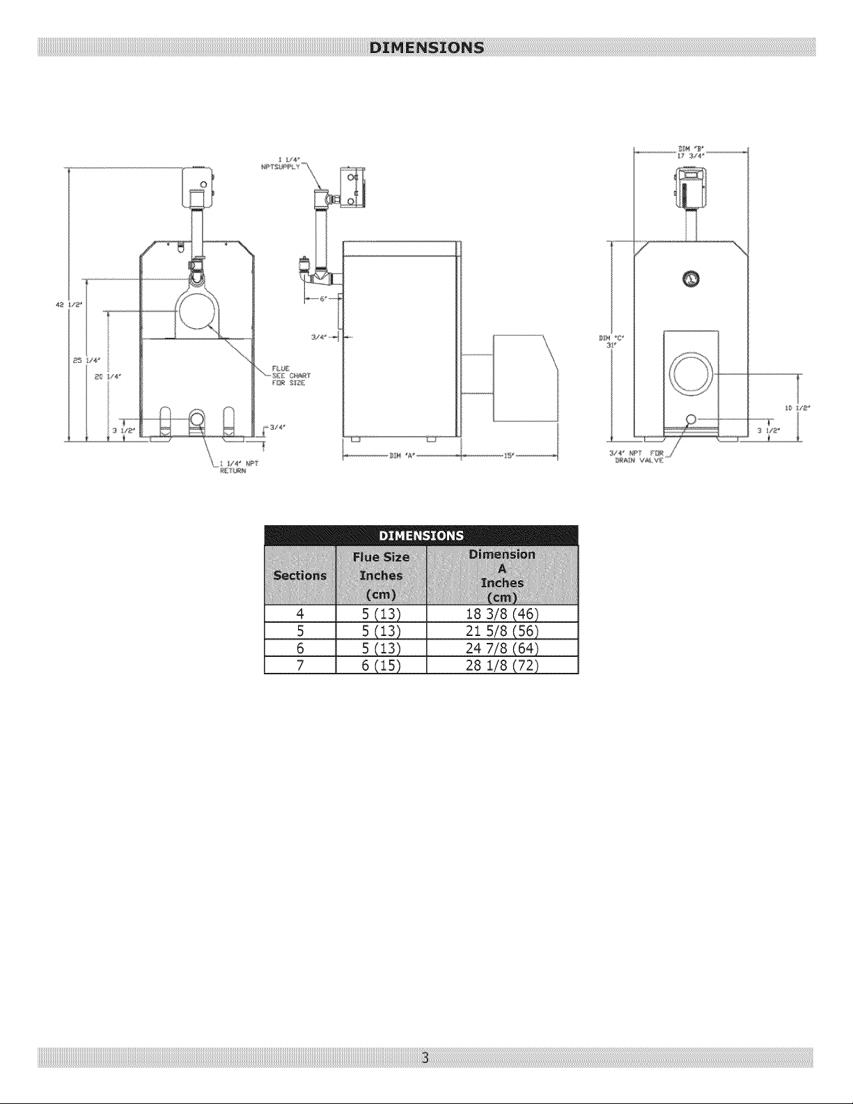
4
5
6
7
5 (13)
5 (13)
5 (13)
6 (15)
18 3/8 (46)
21 5/8 (56)
24 7/8 (64)
28 1/8 (72)
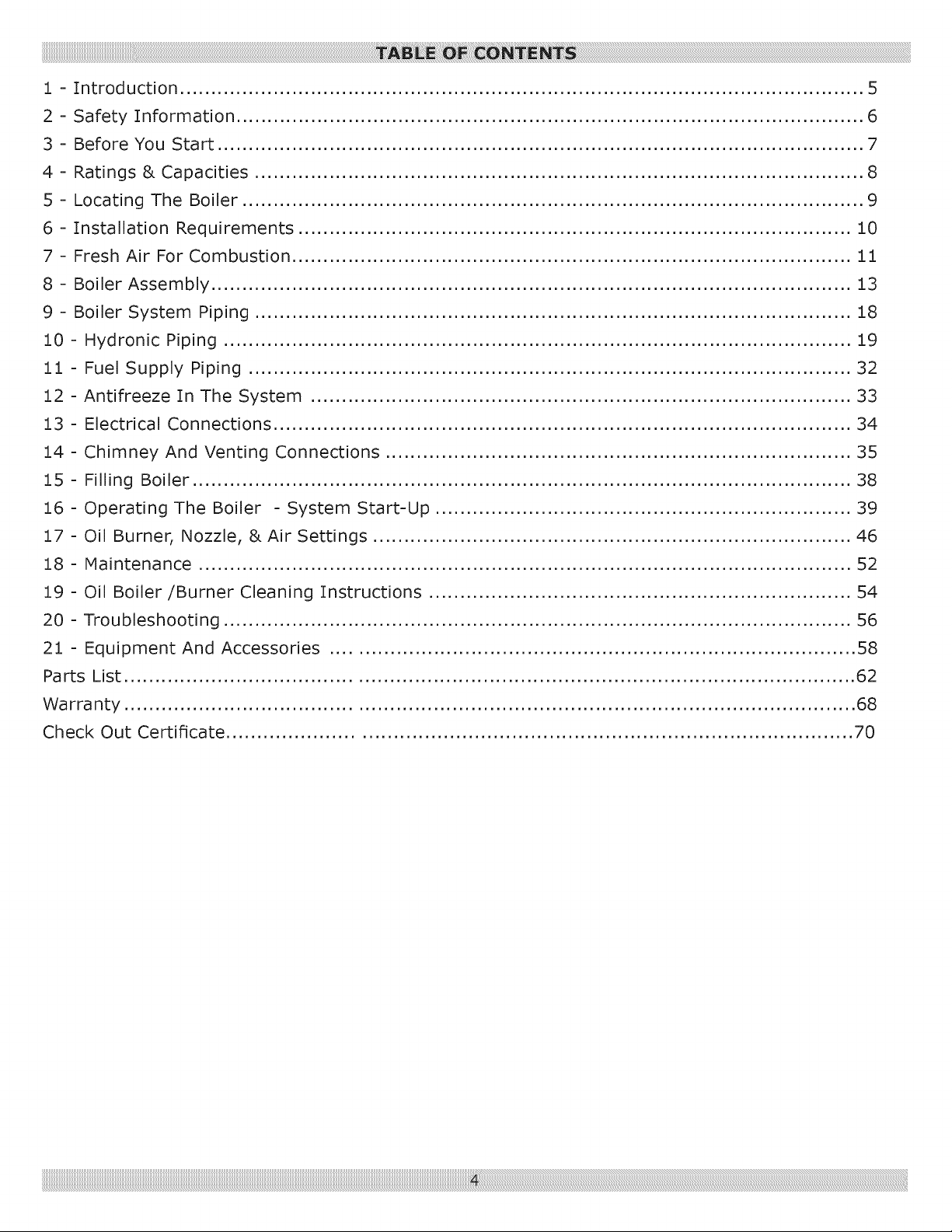
1 - Introduction .............................................................................................................. 5
2 - Safety Information ..................................................................................................... 6
3 - Before You Start ........................................................................................................ 7
4 - Ratings & Capacities .................................................................................................. 8
5 - Locating The Boiler .................................................................................................... 9
6 - Installation Requirements ......................................................................................... 10
7 - Fresh Air For Combustion .......................................................................................... 11
8 - Boiler Assembly ....................................................................................................... 13
9 - Boiler System Piping ................................................................................................ 18
10 - Hydronic Piping ..................................................................................................... 19
11 - Fuel Supply Piping ................................................................................................. 32
12 - Antifreeze In The System ....................................................................................... 33
13 - Electrical Connections ............................................................................................. 34
14 - Chimney And Venting Connections ........................................................................... 35
15 - Filling Boiler .......................................................................................................... 38
16 - Operating The Boiler - System Start-Up ................................................................... 39
17 - Oil Burner, Nozzle, & Air Settings ............................................................................. 46
18 - Maintenance ......................................................................................................... 52
19 - Oil Boiler/Burner Cleaning Instructions .................................................................... 54
20 - Troubleshooting ..................................................................................................... 56
21 - Equipment And Accessories .................................................................................... 58
Parts List ..................................................................................................................... 62
Warranty ..................................................................................................................... 68
Check Out Certificate .................................................................................................... 70
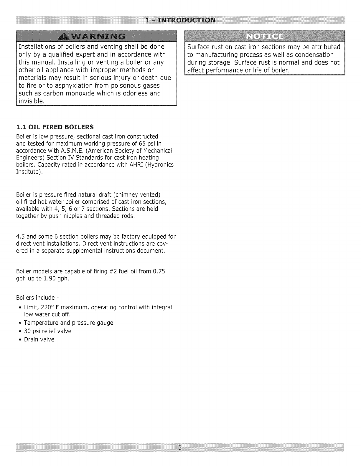
Installationsof boilersandventing shall bedone
only by a qualifiedexpert and in accordancewith
this manual.Installing or ventinga boileror any
other oil appliancewith improper methodsor
materialsmayresult in serious injury or deathdue
to fire or to asphyxiationfrom poisonousgases
suchascarbonmonoxidewhich is odorlessand
invisible.
1,1 OIL FIRED BOILERS
Boiler is low pressure, sectional cast iron constructed
and tested for maximum working pressure of 65 psi in
accordance with A.S.M.E. (American Society of Mechanical
Engineers) Section IV Standards for cast iron heating
boilers. Capacity rated in accordance with AHRI (Hydronics
Institute).
Boiler is pressure fired natural draft (chimney vented)
oil fired hot water boiler comprised of cast iron sections,
available with 4, 5, 6 or 7 sections. Sections are held
together by push nipples and threaded rods.
Surface rust on cast iron sections may be attributed
to manufacturing process as well as condensation
during storage. Surface rust is normal and does not
affect performance or life of boiler.
4,5 and some 6 section boilers may be factory equipped for
direct vent installations. Direct vent instructions are cov-
ered in a separate supplemental instructions document.
Boiler models are capable of firing #2 fuel oil from 0.75
gph up to 1.90 gph.
Boilers include -
• Limit, 220 ° F maximum, operating control with integral
low water cut off.
• Temperature and pressure gauge
• 30 psi relief valve
• Drain valve
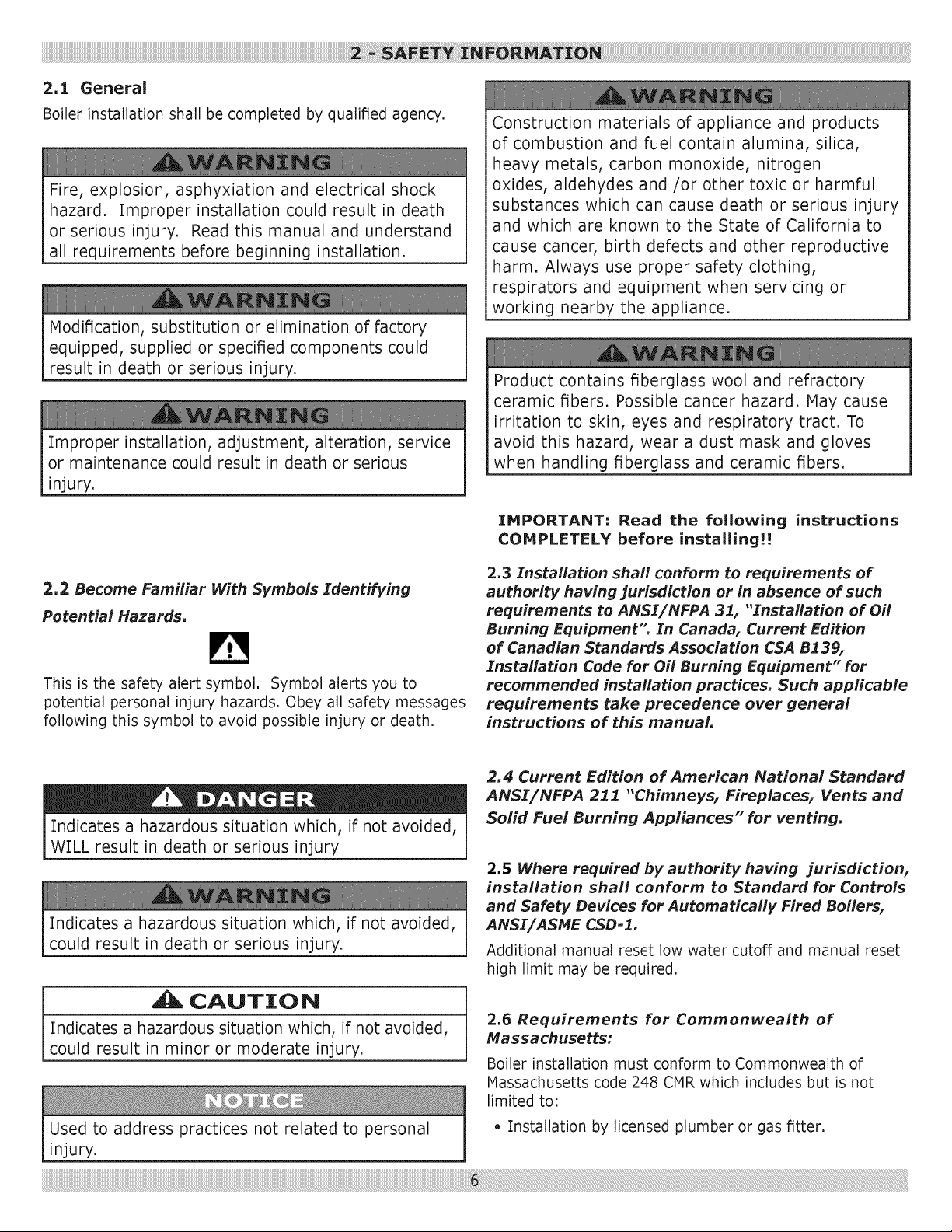
2.1 General
Boiler installation shall be completed by qualified agency.
Fire, explosion, asphyxiation and electrical shock
hazard. Improper installation could result in death
or serious injury. Read this manual and understand
all requirements before beginning installation.
Modification, substitution or elimination of factory
equipped, supplied or specified components could
result in death or serious injury.
Improper installation, adjustment, alteration, service
or maintenance could result in death or serious
injury.
Construction materials of appliance and products
of combustion and fuel contain alumina, silica,
heavy metals, carbon monoxide, nitrogen
oxides, aldehydes and/or other toxic or harmful
substances which can cause death or serious injury
and which are known to the State of California to
cause cancer, birth defects and other reproductive
harm. Always use proper safety clothing,
respirators and equipment when servicing or
working nearby the appliance.
Product contains fiberglass wool and refractory
ceramic fibers. Possible cancer hazard. May cause
irritation to skin, eyes and respiratory tract. To
avoid this hazard, wear a dust mask and gloves
when handling fiberglass and ceramic fibers.
IHPORTANT: Read the following instructions
COHPLETELY before installing!!
2,2 Become Familiar With Symbols Identifying
Potential Hazards.
This is the safety alert symbol, Symbol alerts you to
potential personal injury hazards, Obey all safety messages
following this symbol to avoid possible injury or death,
Indicates a hazardous situation which, if not avoided,
WILL result in death or serious injury
Indicates a hazardous situation which, if not avoided,
could result in death or serious injury.
CAUTION
Indicates a hazardous situation which, if not avoided,
could result in minor or moderate injury.
2.3 Installation shah conform to requirements of
authority having jurisdiction or in absence of such
requirements to ANSI/NFPA 31, "Installation of Oil
Burning Equipment" In Canada, Current Edition
of Canadian Standards Association CSA B139,
Installation Code for Oil Burning Equipment" for
recommended installation practices. Such applicable
requirements take precedence over general
instructions of this manual.
2.4 Current Edition of American National Standard
ANSI/NFPA 211 "Chimneys, Fireplaces, Vents and
Solid Fuel Burning Appliances" for venting.
2.5 Where required by authority having jurisdiction,
installation shall conform to Standard for Controls
and Safety Devices for Automatically Fired Boilers,
ANSI/ASME CSD-I.
Additional manual reset low water cutoff and manual reset
high limit may be required.
2.6 Requirements for Commonwealth of
Massachusetts:
Boiler installation must conform to Commonwealth of
Massachusetts code 248 CMR which includes but is not
limited to:
Used to address practices not related to personal • Installation by licensed plumber or gas fitter.
injury.
3.1 Installation and Operation
]. Do not operate unit if any control, switch, components
or devices have been underwater or subject to water
damage.
2. Before servicing, allow boiler to cool. Always shut off any
electricity and oil supply to boiler when working on it.
3. Inspect oil line and connections for leaks,
4. Verify oil burner nozzle is proper size, Over-firing will
result in early failure of boiler sections, and result in a
potentially dangerous situation,
5. Never vent boiler into enclosed space. Always vent to
the outside, Never vent to another room or inside a
building,
6. Verify adequate air supply for complete combustion,
7. Relief valve automatically lifts open when system
pressure exceeds 30 psi, Before installing relief valve
read manufacturer's instructions. Pipe relief valve to a
safe location. Check with authorities having jurisdiction.
8. Consider system total water volume, temperature,
initial fill pressure and arrangement when sizing and
installing expansion tank, Improperly installed and
sized expansion tank may result in frequent lifting of
relief valve or other heating system problems, Follow
expansion tank manufacturer guidelines for installation,
and sizing,
9. Boiler manufacturer recommends initial fill pressure of
10-12 psi, For higher fill pressures increase expansion
tank's air charge to match fill pressure.
10. Purge heating system of air and gases is critical for
proper circulation and quiet performance, Once the air
is purged, for boiler installations using float type vents,
air vents should be closed for normal operation, If air
is heard or noticed by loss of heat, purge system and
open vents for short period of time,
3.2 Prior To Installing The Boiler
• Verify you have selected right size boiler with proper
capacity, AHRI rating of boiler selected should be greater
than or equal to calculated peak heating load (heat loss)
for building or area(s) served by boiler and associated
hot water heating systems, Use heat loss calculations
based on approved methods, See Figure 1, Page 8
• Boiler must be supplied with proper oil supply and oil
piping, sufficient fresh combustion air, and suitable
electrical supply,
• Connect boiler to suitable venting and piping systems
adequate to distribute heating load,
• Installation is not complete unless pressure relief valve
is installed 3/4" tapping located in supply piping,
• Thermostat must be properly located and installed
• Failure to pipe boiler correctly may result in excessive
noise or other related problems,
Existing Water System Evaluation
A good system will prevent oxygen contamination of boiler
water,
1. Causes of oxygen contamination may be:
A, Addition of excessive make up water as a result of
leaks,
B, Absorption through open tanks and fittings,
C, Oxygen permeable materials in the distribution
system,
2. To insure long product life, oxygen sources must be
eliminated,
Take the following measures:
A, Repair system leaks,
B, Eliminate open tanks from the system,
C, Eliminate and/or repair fittings which allow oxygen
absorption,
D, Use non-permeable materials in the heating system,
4 _ _TING5 & CAPACITI£5
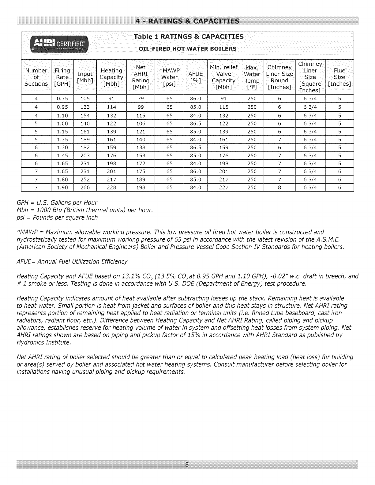
Table % RATINGS & CAPACITIES
OIL-FIRED HOT WATER BOILERS
= J I Net I Min relief Max J Chimney Chimney
Heat ng MAvvv " Liner FlueNumberFiring In ut ' ' I
. AHRI . . AFUE Valve Water Liner Size
of Rate :MPh. _apacIzy vvazer o , , Size Size
Sections [GPH] [ J rMbh] Rating r_s _ [ Yo] Capacty Temp Round [Square , [Inches]
! ! L J . [Mbh] . L_ J . i. [Mbh] . [°F] . [Inches] Inches]
4
4
4
5
5
5
6
6
6
7
7
7
0.75 105
0.95 133
i.i0 154
1.00 140
1.15 161
1.35 189
1,30 182
1.45 203
1,65 231
1,65 231
1,80 252
1,90 266
91
114
132
122
139
161
159
176
198
201
217
228
79
99
115
106
121
140
138
153
172
175
189
198
65 86.0 91 250
65 85.0 115 250
65 84.0 132 250
65 86.5 122 250
65 85,0 139 250
65 84,0 161 250
65 86,5 159 250
65 85.0 176 250
65 84,0 198 250
65 86,0 201 250
65 85.0 217 250
65 84.0 227 250
6
6
6
6
6
7
6
7
7
7
7
8
6 3/4 5
6 3/4 5
6 3/4 5
6 3/4 5
6 3/4 5
6 3/4 5
6 3/4 5
6 3/4 5
6 3/4 5
6 3/4 6
6 3/4 6
6 3/4 6
GPH = U.5. Gallons per Hour
Mbh = i 000 Btu (British thermal units) per hour.
psi = Pounds per square inch
*MAWP = Maximum allowable working pressure. This low pressure oil fired hot water boiler is constructed and
hydrostatically tested for maximum working pressure of 65 psi in accordance with the latest revision of the A.5. M.E.
(American 5ociety of Mechanical Engineers) Boiler and Pressure Vessel Code Section IV Standards for heating boilers.
AFUE= Annual Fuel Utilization Efficiency
Heating Capacity and AFUE based on i3.i% CO2 (i3.5% C02at 0.95 GPH and i.i0 GPH), -0.02" w.c. draft in breech, and
# i smoke or less. Testing is done in accordance with U.S. DOE (Department of Energy) test procedure.
Heating Capacity indicates amount of heat available after subtracting losses up the stack. Remaining heat is available
to heat water. Smafl portion is heat from jacket and surfaces of boiler and this heat stays in structure. Net AHRI rating
represents portion of remaining heat appfied to heat radiation or terminal units (i.e. finned tube baseboard, cast iron
radiators, radiant floor, etc.). Difference between Heating Capacity and Net AHRI Rating, cafled piping and pickup
aflowance, establishes reserve for heating volume of water in system and offsetting heat losses from system piping. Net
AHRI ratings shown are based on piping and pickup factor of i5% in accordance with AHRI Standard as published by
Hydronics Institute.
Net AHRI rating of boiler selected should be greater than or equal to calculated peak heating load (heat loss) for building
or area(s) served by boiler and associated hot water heating systems. Consult manufacturer before selecting boiler for
installations having unusual piping and pickup requirements.
Fire hazard. Do not be install on carpeting. Failure
to follow these instructions could result in death or
serious injury.
I. Boiler is suitable for installation on combustible floor-
ing. Do not install boiler on carpeting.
2. Locate boiler in front of final position before removing
crate.
3. Locate unit so vent pipe connection to chimney will be
short and direct.
4. For basement installation, provide solid elevated base,
such as concrete, if floor is not level, or if water may be
encountered on floor around boiler,
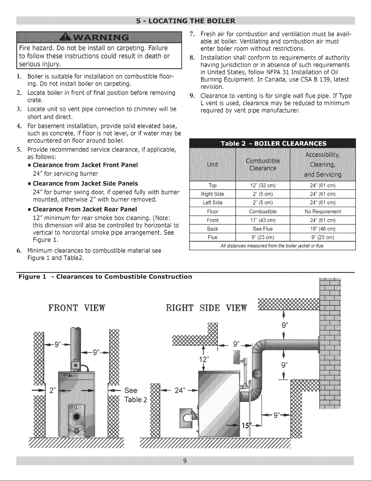
5. Provide recommended service clearance, if applicable,
as follows:
• Clearance from Jacket Front Panel
24" for servicing burner
• Clearance from Jacket Side Panels
24" for burner swing door, if opened fully with burner
mounted, otherwise 2" with burner removed.
• Clearance From Jacket Rear Panel
12" minimum for rear smoke box cleaning. (Note:
this dimension will also be controlled by horizontal to
vertical to horizontal smoke pipe arrangement. See
Figure 1.
6. Minimum clearances to combustible material see
Figure 1 and Table2.
7. Fresh air for combustion and ventilation must be avail-
able at boiler. Ventilating and combustion air must
enter boiler room without restrictions.
8. Installation shall conform to requirements of authority
having jurisdiction or in absence of such requirements
in United States, follow NFPA 31 Installation of Oil
Burning Equipment. In Canada, use CSA B 139, latest
revision.
9. Clearance to venting is for single wall flue pipe. If Type
L vent is used, clearance may be reduced to minimum
required by vent pipe manufacturer.
Top 12" (32 cm) 24" (61 cm)
Right Side 2" (5 cm) 24" (61 cm)
LeftSide 2" (5 cm) 24" (61 cm)
Floor Combustible No Requirement
Front 17" (43 cm) 24" (61 cm)
Back See Flue 18" (46 cm)
Flue 9" (23cm) 9" (23 cm)
All distancesmeasuredfromtheboilerjacket orflue.
Figure i - Clearances to Combustible Construction
See 24"
Table 2
!i!i!i!i!i!i!i!i!i!i!i!i!i!i!i!i!i!i!i!i!i!i!i!i!i!i!i!i!i!i!i!i!i!i!i!i!i!i!i!i!i!i!i!i!i!i!i!i!i!i!i!i!i!i!i!i!i!i!i!i!i!i!i!i!i!i!i!i!i!i!i!i!i!i!i!i!i!i!i!i!i!i!i!i!i!i!i!i!i!i!i!i!i!i!i!i!i!i!i!i!i!i!i!i!i!i!i!i!i!i!i!i!i!i!i!i!i!i!i!i!i!i!i!i!i!i!i!i!i!i!i!i!i!i!i!i!i!i!i!i!i!i!i!i!i!i!i!i!i!i!i!i!i!i!i!i!i!i!i!i!i!i!i!i!i!i!i!i!i!i!i!i!i!i!i!i!i!i!i!i!i!i!i!i!i!i!i!i!i!i!i!i!i!i!i!i!i!i!i!i!i!i!i!i!i!i!i!i!i!i!i!i!i!i!i!i!i!i!i!i!i!i!i!i!i!i!i!i!i!i!i!i!i!i!i!i!i!i!i!i!i!i!i!i!i!i!i!i!i!i!i!i!i!i!i!i!i!i!i!i!i!i!i!i!i!i!i!i!i!i!i!i!i!i!i!i!i!i!i!i!i!i!i!i!i!i!i!i!i!i!i!i!i!i!i!i!i!i!i!i!i!i!i!i!i!i!i!i!i!i!i!i!i!i!i!i!i!i!i!i!i!i!i!i!i!i!i!i!i!i!i!i!i!i!i!i!i!i!i!i!i!i!i!i!i!i!i!i!i!i!i!i!i!i!i!i!i!i!i!i!i!i!i!i!i!i!i!i!i!i!i!i!i!i!i!i!i!i!i!i!i!iil_i_ii_il_ii_ii_ii_ii_ii_ii_ii_il_ii_ii_ii_ii_ii_ii_ii_il_ii_ii_ii_ii_ii_ii_ii_il_ii_ii_ii_ii_ii_ii_ii_il_ii_ii_ii_ii_ii_ii_ii_il_ii_ii_ii_ii_ii_ii_ii_il_ii_ii_ii_ii_ii_ii_ii_il_ii_ii_ii_ii_ii_ii_ii_il_ii_ii_ii_ii_ii_ii_ii_il_ii_ii_ii_ii_ii_ii_ii_il_ii_ii_ii_ii_ii_ii_ii_il_ii_ii_ii_ii_ii_ii_ii_il_ii_ii_ii_ii_ii_ii_ii_il_ii_ii_ii_ii_ii_ii_ii_il_ii_ii_ii_ii_ii_ii_ii_il_ii_ii_ii_ii_ii_ii_ii_il_ii_ii_ii_ii_ii_ii_ii_il_ii_ii_ii_ii_ii_ii_ii_il_ii_ii_ii_ii_ii_ii_ii_il_ii_ii_ii_ii_ii_ii_ii_il_ii_ii_ii_ii_ii_ii_ii_il_ii_ii_ii_ii_ii_ii_ii_il_ii_ii_ii_ii_ii_ii_ii_il_ii_ii_ii_ii_ii_ii_ii_il_ii_ii_ii_ii_ii_ii_ii_il_ii_ii_ii_ii_ii_ii_ii_il_ii_ii_ii_ii_ii_ii_ii_il_ii_ii_ii_ii_ii_ii_ii_il_ii_ii_ii_ii_ii_ii_ii_il_ii_ii_ii_ii_ii_ii_ii_il_ii_ii_ii_ii_ii_ii_ii_il_ii_ii_ii_ii_ii_ii_ii_il_ii_ii_ii_ii_ii_ii_ii_il_ii_ii_ii_ii_ii_ii_ii_il_ii_ii_ii_ii_ii_ii_ii_il_ii_ii_ii_ii_ii_ii_ii_il_ii_ii_ii_ii_ii_ii_ii_il_ii_ii_ii_ii_ii_ii_ii_il_ii_ii_ii_ii_ii_ii_ii_il_ii_ii_ii_ii_ii_ii_ii_il_ii_ii_ii_ii_ii_ii_ii_il_ii_ii_ii_ii_ii_ii_ii_il_ii_ii_ii_ii_ii_ii_ii_il_ii_ii_ii_ii_ii_ii_ii_il_ii_ii_ii_ii_ii_ii_ii_il_ii_ii_ii_ii_ii_ii_ii_il_ii_ii_ii_ii_ii_ii!ii!ii!iilil:!i_!i!_!
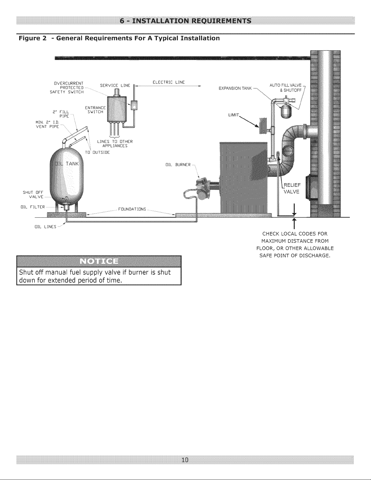
Figure 2 - General Requirements For A Typical Installation
EXPAN8 ON TANK
VALVE
OI_L LINES ......
Shut off manual fuel supply valve if burner is shut
down for extended period of time.
T
CHECK LOCAL CODES FOR
MAXIMUM DISTANCE FROM
FLOOR, OR OTHER ALLOWABLE
SAFE POINT OF DISCHARGE.
Asphyxiation,fire hazard.Donotobstructair
openingsto combustionarea.Followinstructions
below,to maintainadequatecombustionair.
Install outside air intake if used with a fireplace or
kitchen or bathroom exhaust fan. These devices rob
boiler and water heater of combustion air.
I. Determine volume of space (boiler room), Rooms
communicating directly with the space in which
appliances are installed, through openings not furnished
with doors, are considered a part of the space,
Volume (ft 3) = Length (ft.) x Width (ft.) x Height (ft.)
2. Determine total input of all appliances in the space,
Add inputs of all appliances in the space and round the
result to the nearest 1000 BTU/hr,
3. Determine type of space. Divide Volume by total input
of all appliances in space, If the result is greater than
or equal to 50 ft3/1000 BTU/hr, then it is considered
an unconfined space, If the result is less than 50
ft3/1000 BTU/hr, then the space is considered a
confined space.
4. When a boiler is located in an unconfined space of a
conventionally constructed building, fresh air infiltration
through cracks around windows and doors normally
provides adequate air for combustion and ventilation.
5. Provide outdoor air for boiler located in a confined
space or an unconfined space in a building of unusually
tight construction. Outdoor air may be provided with
the use of two permanent openings which communicate
directly or by duct with the outdoors or spaces
(ventilated crawl or attic) freely communicating with
the outdoors. Locate one opening within 12 inches
of top of space. Locate remaining opening within 12
inches of bottom of space. Size each opening per the
following:
A. Direct communication with outdoors:
Minimum free area of 1 square inch per 4,000 BTU
per hour input of all equipment in space,
Bg
Vertical Ducts: Minimum free area of 1 square
inch per 4,000 BTU per hour input of all equipment
in space. Duct cross-sectional area shall be same
as opening free area.
Cg
Horizontal Ducts: Minimum free area of 1 square
inch per 2,000 BTU per hour input of all equipment
in space. Duct cross-sectional area shall be same
as opening free area.
Alternate method for boiler located within
confined space: Use indoor air if two permanent
openings communicate directly with additional space(s)
of sufficient volume such that the combined volume of
all spaces meet criteria for unconfined space. Size each
opening for minimum free area of i square inch per
1,000 BTU per hour input of all equipment in spaces,
but not less than 100 square inches.
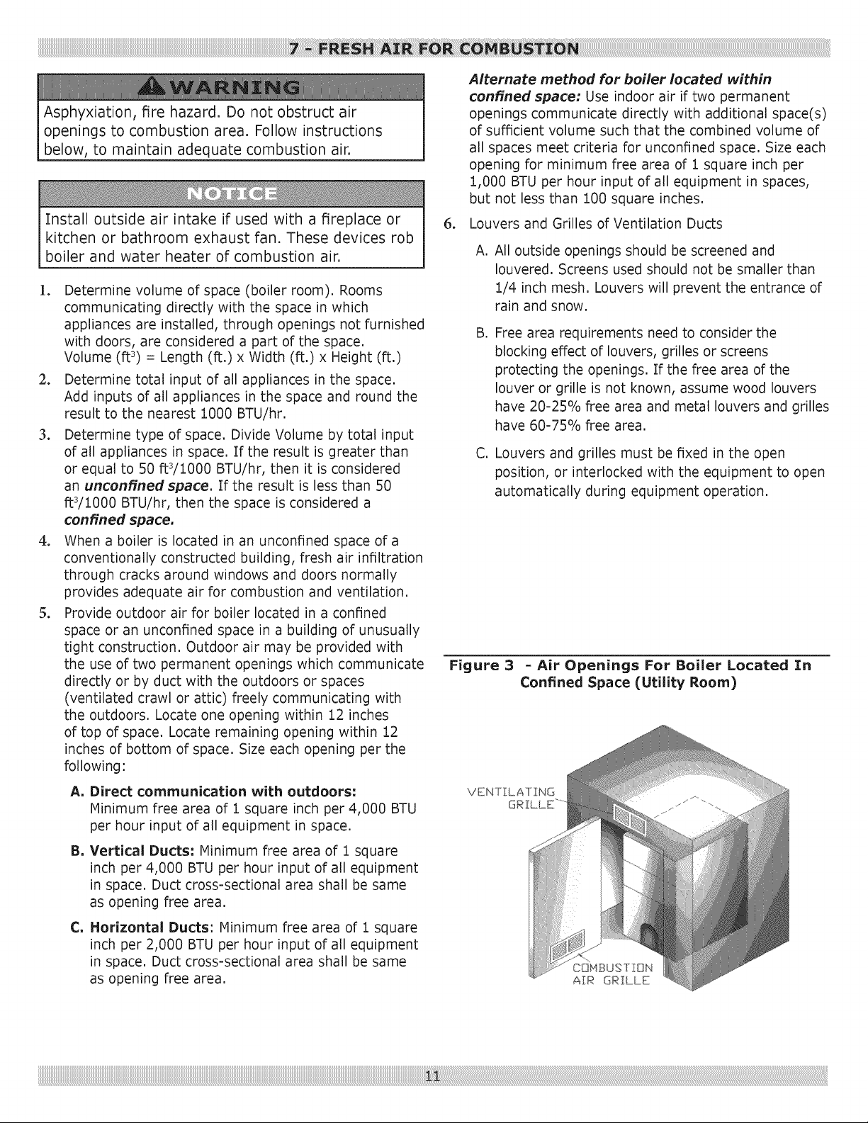
6. Louvers and Grilles of Ventilation Ducts
A,
All outside openings should be screened and
Iouvered. Screens used should not be smaller than
1/4 inch mesh. Louvers will prevent the entrance of
rain and snow.
B,
Free area requirements need to consider the
blocking effect of louvers, grilles or screens
protecting the openings. If the free area of the
louver or grille is not known, assume wood louvers
have 20-25% free area and metal louvers and grilles
have 60-75% free area.
C, Louvers and grilles must be fixed in the open
position, or interlocked with the equipment to open
automatically during equipment operation,
Figure 3 - Air Openings For Boiler Located fn
Confined Space (Utility Room)
VEN] EA] ZNG
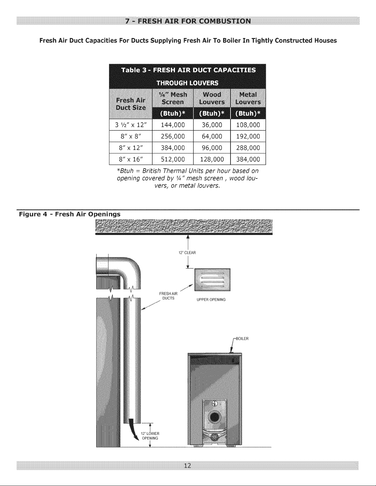
Fresh Air Duct Capacities For Ducts Supplying Fresh Air To Boiler In Tightly Constructed Houses
Figure 4 - Fresh Air Openings
3 V2"x 12"
8" x 8"
8" x 12"
8" x 16"
*Btuh = British Thermal Units per hour based on
opening covered by _ " mesh screen, wood lou-
144,000
256,000
384,000
512,000
vers, or metal louvers.
t2 CIEAR
36,000
64,000
96,000
128,000
i08,000
192,000
288,000
384,000

1. Remove Crate
A. Remove all fasteners at crate skid.
B. Lift outside container and remove all other inside
protective spacers and bracing. Remove burner and
miscellaneous parts boxes.
2. Remove Boiler from skid. Boiler is secured to base
with 4 screws. Remove all securing hardware.
3. Move boiler into permanent position by sliding or
walking into place,
4o Do not drop boiler, Do not bump boiler jacket
against floor,
5. Open burner swing door. Proper method to closing
and securing burner swing door opened for inspection,
cleaning or field service.
A. Loosen and remove non-hinged side latching
hardware.
B. Remove hinged side latching hardware.
C. Door can be swung to full open position
approximately 90 to 120 degrees with the burner
mounted providing there is 22" of clearance to the
adjacent wall.
Burner door may come off hinges if lifted when
opened.
If reduced clearance prevents door from opening fully, one
of the following can provide full access:
• Burner can be removed to allow full rotation of door.
Door with burner mounted can be lifted off hinges and
set aside during servicing.
• Door mounting hardware is reversible from left side
hinge (as shipped) to right side hinge. To reverse hinge
arrangement. See Figure 5.
• Lift door off mounting eye bolts and set aside. Remove
mounting eye bolts from left side. Move door mounting
eye bolts to right side. Tighten both sets of hardware.
Lift door and place integral cast hinge pins on door into
slotted mounting bracket holes.
Recommend hinges be on same side as flexible oil line in
order to swing door open.
.
Inspect Swing door insulation and rope gasket,
A. Inspect fiber rope located on swing door. Evenly
distribute rope around perimeter of door groove
do not bunch or overhang. There must not be
a gap where two ends of rope meet. Repair or
replace if rope is damaged or if there is gap
between ends.
B. Inspect burner swing door insulation for damage.
C. Combustion chamber and raised portion between
2nd and 3rd pass flue ways make an impression
in door insulation as designed.
D. Do not close and secure door at this time,
Figure 5 - Reversible Hinge
AS HINGE
(BOLT iNTO FRONT SECTION)
AS HINGE
For purpose of these instructions, all pipe
connections shall use pipe dope or Teflon tape to
assure water tight connections unless otherwise
instructed. Steps 6 thru 16, Figure 10, Page 15.
7. Open accessory carton and remove contents. Identify
components using illustrations throughout this section
applicable to your installation.
8. Remove top panel. Remove sheet metal screws
securing top panel to jacket rear panel. Slide top panel
towards front of boiler and lift off of side panel.
9. Locate shorter of two 1 1/4" adapters. Thread thru
insulation slot into supply port in rear of boiler. Locate
1 1/4 x 3/4 x 1 1/4 elbow and assemble onto adapter.
Verify connections are tight with outlet facing directly
up. See Figure 6.
]0. Locate longer of the two 1 1/4" adapters. Assemble
onto elbow.
Figure 6 - Adapter Assembled Onto Elbow
1 1/4" ADAPTER-
1 1/4x 3/4x 1 1/4
RELIEF VALVE
ELBOW
Donot installvalvebetweenboilerandcontrols
manifoldor reliefvalve.
]1o Locate cast 1 1/4 x 1 1/4 x 3/4 tee and assemble on
long female adapter with 3/4" tapping facing toward
front of boiler and joint is water tight,
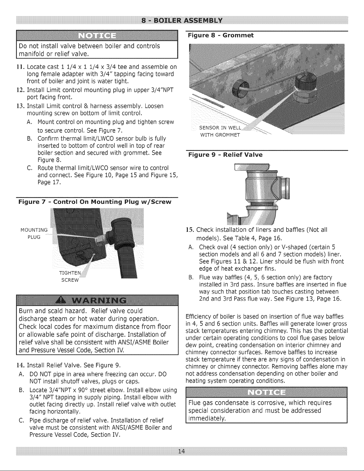
12o Install Limit control mounting plug in upper 3/4"NPT
port facing front.
13oInstall Limit control & harness assembly. Loosen
mounting screw on bottom of limit control.
A. Mount control on mounting plug and tighten screw
to secure control. See Figure 7. SENSOR IN WELL
B. Confirm thermal limit/LWCO sensor bulb is fully
inserted to bottom of control well in top of rear
boiler section and secured with grommet. See
Figure 8.
C. Route thermal limit/LWCO sensor wire to control
and connect. See Figure 10, Page 15 and Figure 15,
Page 17.
Figure 7 - Control On Mounting Plug w/Screw
Figure 8 - Grommet
WITH GROMMET
Figure 9 - Relief Valve
MOUNTING
PLUG
Burn and scald hazard. Relief valve could
discharge steam or hot water during operation.
Check local codes for maximum distance from floor
or allowable safe point of discharge. Installation of
relief valve shall be consistent with ANSI/ASME Boiler
and Pressure VesselCode, Section IV.
]4o Install Relief Valve. See Figure 9.
A. DO NOT pipe in area where freezing can occur. DO
NOT install shutoff valves, plugs or caps.
B. Locate 3/4"NPT x 90 ° street elbow. Install elbow using
3/4" NPT tapping in supply piping. Install elbow with
outlet facing directly up. Install relief valve with outlet
facing horizontally.
C. Pipe discharge of relief valve. Installation of relief
valve must be consistent with ANSI/ASME Boiler and
Pressure Vessel Code, Section IV.
15. Check installation of liners and baffles (Not all
models). See Table 4, Page 16.
A. Check oval (4 section only) or V-shaped (certain 5
section models and all 6 and 7 section models) liner.
See Figures 11 & 12. Liner should be flush with front
edge of heat exchanger fins.
B. Flue way baffles (4, 5, 6 section only) are factory
installed in 3rd pass. Insure baffles are inserted in flue
way such that position tab touches casting between
2nd and 3rd Pass flue way. See Figure 13, Page 16.
Efficiency of boiler is based on insertion of flue way baffles
in 4, 5 and 6 section units. Baffles will generate lower gross
stack temperatures entering chimney. This has the potential
under certain operating conditions to cool flue gases below
dew point, creating condensation on interior chimney and
chimney connector surfaces. Remove baffles to increase
stack temperature if there are any signs of condensation in
chimney or chimney connector. Removing baffles alone may
not address condensation depending on other boiler and
heating system operating conditions.
Flue gas condensate is corrosive, which requires
special consideration and must be addressed
immediately.
____________________________________________________________________________________________________________________________________________________________________________________________________________________________________________________________________________________________________!_!!ii!ii!ii!i!i_!ii!_!iiiiiiiii_ii_ii_ii_!_!_i!_6!i_i:ii_;!_i:!i_i_!i_!i_ii_!i_ii_ii:!_!ii!:ii_iii'_i_i_ii_i_i_!i,!i,!i,!i,!i,!i,!i,!i,!i,!i,!i,!i,!i,!i,!i,!i,!i,!i,!i,!i,!i,!i,!i,!i,!i,!i,!i,!i,!i,!i,!i,!i,!i,!i,!i,!i,!i,!i,!i,!i,!i,!i,!i,!i,!i,!i,!i,!i,!i,!i,!i,!i,!i,!i,!i,!i,!i,!i,!i,!i,!i,!i,!i,!i,!i,!i,!i,!i,!i,!i,!i,!i,!i,!i,!i,!i,!i,!i,!i,!i,!i,!i,!i,!i,!i,!i,!i,!i,!i,!i,!i,!i,!i,!i,!i,!i,!i,!i,!i,!i,!i,!i,!i,!i,!i,!i,!i,!i,!i,!i,!i,!i,!i,!i,!i,!i,!i,!i,!i,!i,!i,!i,!i,!i,!i,!i,!i,!i,!i,!i,!i,!i,!i,!i,!i,!i,!i,!i,!i,!i,!i,!i,!i,!i,!i,!i,!i,!i,!i,!i,!i,!i,!i,!i,!i,!i,!i,!i,!i,!i,!i,!i,!i,!i,!i,!i,!i,!i,!i,!i,!i,!i,!i,!i,!i,!i,!i,!i,!i,!i,!i,!i,!i,!i,!i,!i,!i,!i,!i,!i,!i,!i,!i,!i,!i,!i,!i,!i,!i,!i,!i,!i,!i,!i,!i,!i,!i,!i,!i,!i,!i,!i,!i,!i,!i,!i,!i,!i,!i,!i,!i,!i,!i,!i,!i,!i,!i,!i,!i,!i,!i,!i,!i,!i,!i,!i,!i,!i,!i,!i,!i,!i,!i,!i,!i,!i,!i,!i,!i,!i,!i,!i,!i,!i,!i,!i,!i,!i,!i,!i,!i,!i,!i,!i,!i,!i,!i,!i,!i,!i,!i,!i,!i,!i,!i,!i,!i,!i,!i,!i,!i,!i,!i,!i,!i,!i,!i,!i,!i,!i,!__;
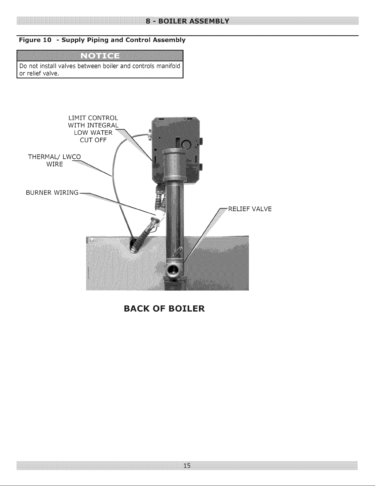
Figure 10 - Supply Piping and Control Assembly
Do not install valves between boiler and controls manifold
or relief valve.
LIMIT CONTROL
WITH INTEGRAL
LOW WATER
CUT OFF
THERMAL/ LWCO
WIRE
BURNER
BACK OF BOILER
, RELIEF VALVE
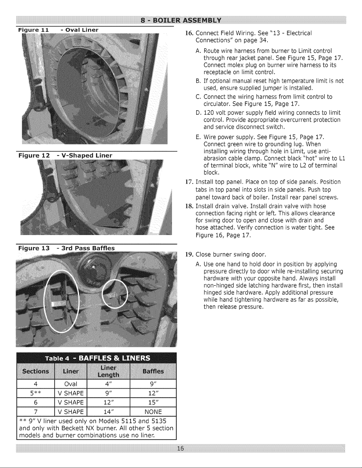
Figure 11 = Oval Liner
Figure 12 -V-Shaped Liner
]6. Connect Field Wiring. See "13 - Electrical
Connections" on page 34.
A. Route wire harness from burner to Limit control
through rear jacket panel. See Figure 15, Page 17.
Connect molex plug on burner wire harness to its
receptacle on limit control.
B. If optional manual reset high temperature limit is not
used, ensure supplied jumper is installed.
C. Connect the wiring harness from limit control to
circulator. See Figure 15, Page 17.
D. 120 volt power supply field wiring connects to limit
control. Provide appropriate overcurrent protection
and service disconnect switch.
E,
Wire power supply. See Figure 15, Page 17.
Connect green wire to grounding lug. When
installing wiring through hole in Limit, use anti-
abrasion cable clamp. Connect black "hot" wire to L1
of terminal block, white "N" wire to L2 of terminal
block.
]7.
Install top panel. Place on top of side panels. Position
tabs in top panel into slots in side panels. Push top
panel toward back of boiler. Install rear panel screws.
]8.
Install drain valve. Install drain valve with hose
connection facing right or left. This allows clearance
for swing door to open and close with drain and
hose attached. Verify connection is water tight. See
Figure 16, Page 17.
4 Oval 4" 9"
5** V SHAPE 9" 12"
6 V SHAPE 12" 15"
7 V SHAPE 14" NONE
** 9" V liner used only on Models 5115 and 5135
and only with Beckett NX burner. All other 5 section
models and burner combinations use no linen
19. Close burner swing door.
A. Use one hand to hold door in position by applying
pressure directly to door while re-installing securing
hardware with your opposite hand. Always install
non-hinged side latching hardware first, then install
hinged side hardware. Apply additional pressure
while hand tightening hardware as far as possible,
then release pressure.
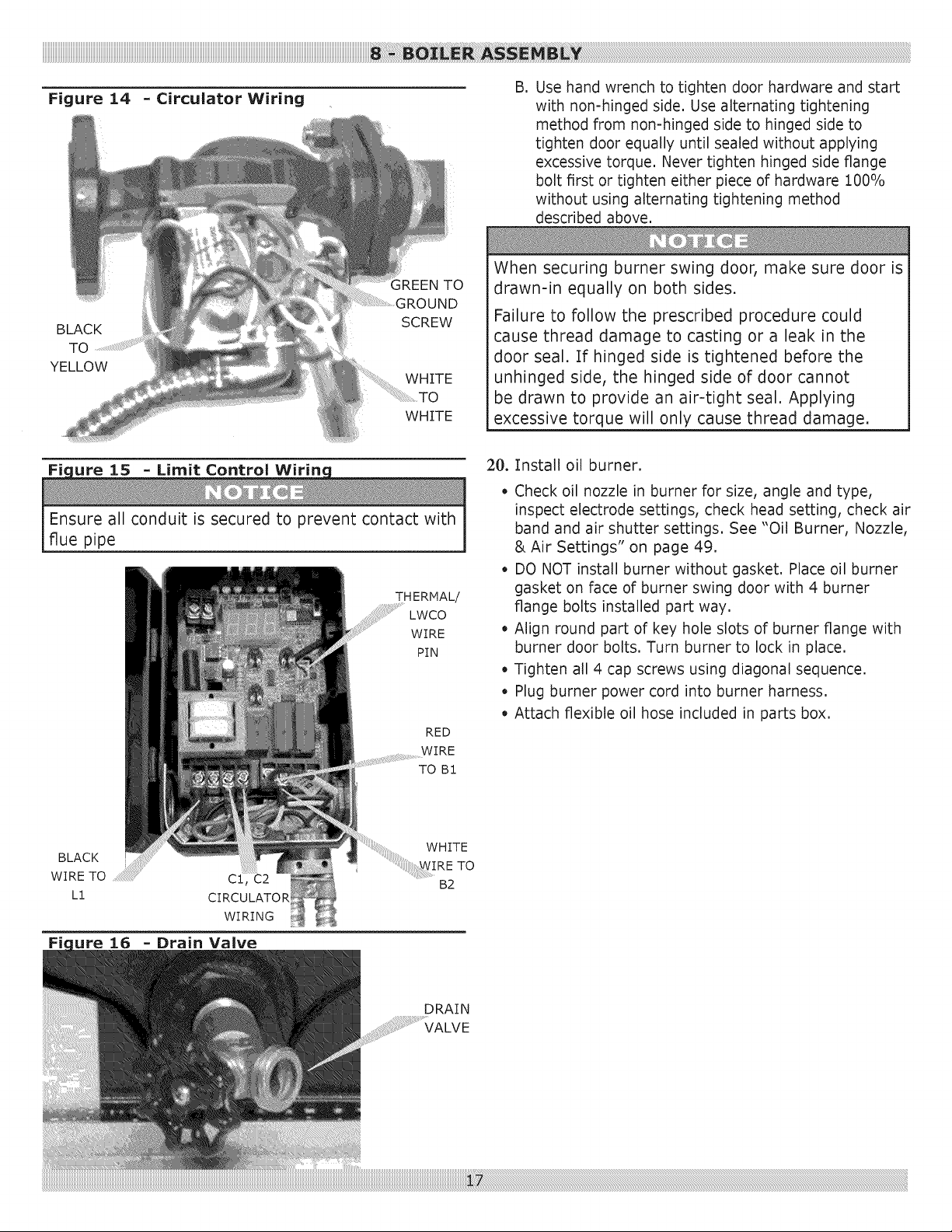
Figure 14 - Circulator Wiring
B. Use hand wrench to tighten door hardware and start
with non-hinged side, Use alternating tightening
method from non-hinged side to hinged side to
tighten door equally until sealed without applying
excessive torque, Never tighten hinged side flange
bolt first or tighten either piece of hardware 100%
without using alternating tightening method
described above,
;REEN TO
BLACK
TO
YELLOW
SCREW
WHITE
WHITE
Fk ure 15 Limit Control Wirinc
Ensure all conduit is secured to prevent contact with
flue pipe
THERMAL/
.... LWCO
WIRE
PIN
RED
WIRE
TO BI
When securing burner swing door, make sure door is
drawn-in equally on both sides.
Failure to follow the prescribed procedure could
cause thread damage to casting or a leak in the
door seal. If hinged side is tightened before the
unhinged side, the hinged side of door cannot
be drawn to provide an air-tight seal. Applying
excessive torque will only cause thread damage.
20. Install oil burner.
o
Check oil nozzle in burner for size, angle and type,
inspect electrode settings, check head setting, check air
band and air shutter settings. See "Oil Burner, Nozzle,
& Air Settings" on page 49.
• DO NOT install burner without gasket. Place oil burner
gasket on face of burner swing door with 4 burner
flange bolts installed part way.
• Align round part of key hole slots of burner flange with
burner door bolts. Turn burner to lock in place.
• Tighten all 4 cap screws using diagonal sequence.
• Plug burner power cord into burner harness.
• Attach flexible oil hose included in parts box.
......... W HITE
BLACK ....':::WIRE
WIRE TO .................................................... B2
L1
WIRING
Fic ure 16 Drain live
DRAIN
VALVE
TO

9.1 Connect System Supply And Return Piping
To Boiler
Connect system supply and return piping to correct
boiler fittings,
Size system circulator to supply sufficient flow (GPM)
to allow 20°F temperature differential in system,
When sizing system circulator, use single most
restrictive zone to determine maximum pressure
drop.
]. Boiler used in connection with refrigeration systems,
install boiler so chilled medium is piped in parallel with
heating boiler using appropriate valves to prevent
chilled medium from entering boiler. See Figure 28,
Page 31.
2. If boiler is connected to heating coils located in air
handling units exposed to refrigerated air, equip boiler
piping with flow control valves to prevent gravity
circulation of boiler water during operation of cooling
system.
3, Limit control includes low water cutoff function, sensing
water level at control well in top of the rear boiler
section. Periodic inspection and testing is necessary
per instructions provided with limit control.
4, When installation of boiler is for new heating system,
install all radiation units (panels, radiators, baseboard,
or tubing) and supply and return mains. After heating
system piping and components have been installed,
make final connection of system piping to boiler.
Recommend mount circulating pump on supply side
piping, such that it pumps away from expansion tank,
5, Hot water boiler installed above radiation level must
be equipped with low water cut off device. This boiler
is factory equipped with low water cutoff. Periodic
inspection is necessary, per manufacturer's specific
instructions.
6, When connecting cold water supply to pressure
reducing valve, make sure clean water supply is
available. When water supply is from well or pump,
install sand strainer at pump.
9.2 Bypass Piping
See Piping Diagrams for illustrations for this section.
Bypass piping may be required for applications listed
below. Failure to do so may cause damage due to thermal
shock and sustained condensation within the boiler.
Protect boiler from sustained operation of return water
temperatures lower than 130°F (54C). Occasionally,
temperatures as low as 70°F (21C) may return back to
boiler when a zone that has not been activated for some
time is opened. However, most residential systems with
finned-tube (aluminum=copper) baseboard radiation
contain low volume of water and will not adversely affect
boiler. Systems with finned-tube baseboard radiation
typically do not require bypass.
Bypass piping details shown in piping diagrams must be
used for any one of following conditions:
• All large water content systems, including cast iron
standing radiators, cast iron baseboard, converted
two-pipe steam systems, converted gravity circulation
systems and other similar systems.
• Any system, including finned-tube baseboard, with
priority domestic hot water zone.
Install 3/4inch bypass line as shown in piping diagrams for
systems identified above.
Bypass valve cannot protect boiler from sustained
condensing operation for low temperature applications such
as radiant floor heating. These types of system require
active controls that prevent return of cold return water to
boiler.
Refer to Radiant Professional's Alliance (RPA)
www.radiantprofessionalsalliance.org for piping
recommendations for non-condensing boiler applications.
 Loading...