

Page 1
TANKLESS HEATER COIL
INSTALLATION INSTRUCTIONS
Kit # 550002988
Kit installation shall be completed by qualied agency.
WARNING
!
Fire, explosion, asphyxiation and electrical shock
hazard. Improper installation could result in
death or serious injury. Read this instruction
and understand all requirements, including
requirements of authority having jurisdiction, before
beginning installation. Installation not complete
until appliance operation veried per Installation,
Operation & Maintenance Manual provided with
boiler.
NOTICE
Do not use a tankless coil if your water is
excessively hard with lime or other deposits which
will accumulate inside the coil.
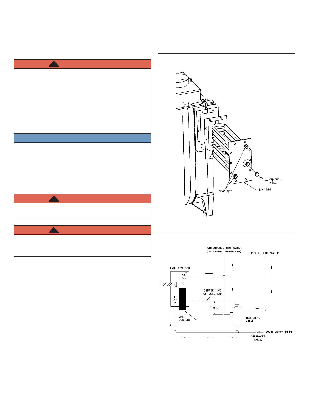
Figure 1
When using tankless coil, boiler is congured so boiler
control (either Honewell L7248L or Hydrolevel 3250)
operates in conjunction with Honeywell L4006A low limit
control mounted on well in tankless heater cover plate
WARNING
!
Electrical shock hazard. Turn OFF electrical power
supply at service panel.
WARNING
!
Burn hazard. Verify heat exchanger has cooled
or use appropriate personal protection equipment
before servicing.
1.
Unpack coil, gasket, low limit control, control well, and
wiring harness.
2.
Drain boiler and system, if necessary.
3.
Remove jacket cover panel (if provided) on right side
jacket.
4.
Remove 10 screws holding coil opening cover plate and
discard.
5.
Remove cover plate and gasket and discard.
6.
Install ten (10) 3/8"-16 x 1½" studs into bolt holes in
preparation for installing tankless coil.
7.
Place new gasket over coil and up against inside face
plate. Insert coil into boiler opening. Verify arrow
stamped in the face plate points upward and the word
“TOP” (if shown) is at the top. Install ten (10) 3/8" 16 hex nuts. Tighten evenly and snugly in crisscross
pattern. Do not exert extreme pressure and snap the
bolts.
Figure 2
P/N 240010786 Rev. A [07/2014]
Page 2
TANKLESS HEATER COIL INSTALLATION INSTRUCTIONS
L7248L
L4006 LOW LIMIT
HYDROLEVEL 3250
8.
Install control well in 3/4” tapping in coil face plate.
Reinstall the jacket cover panel (if provided) removing
the knockouts for tankless coil connections.
9.
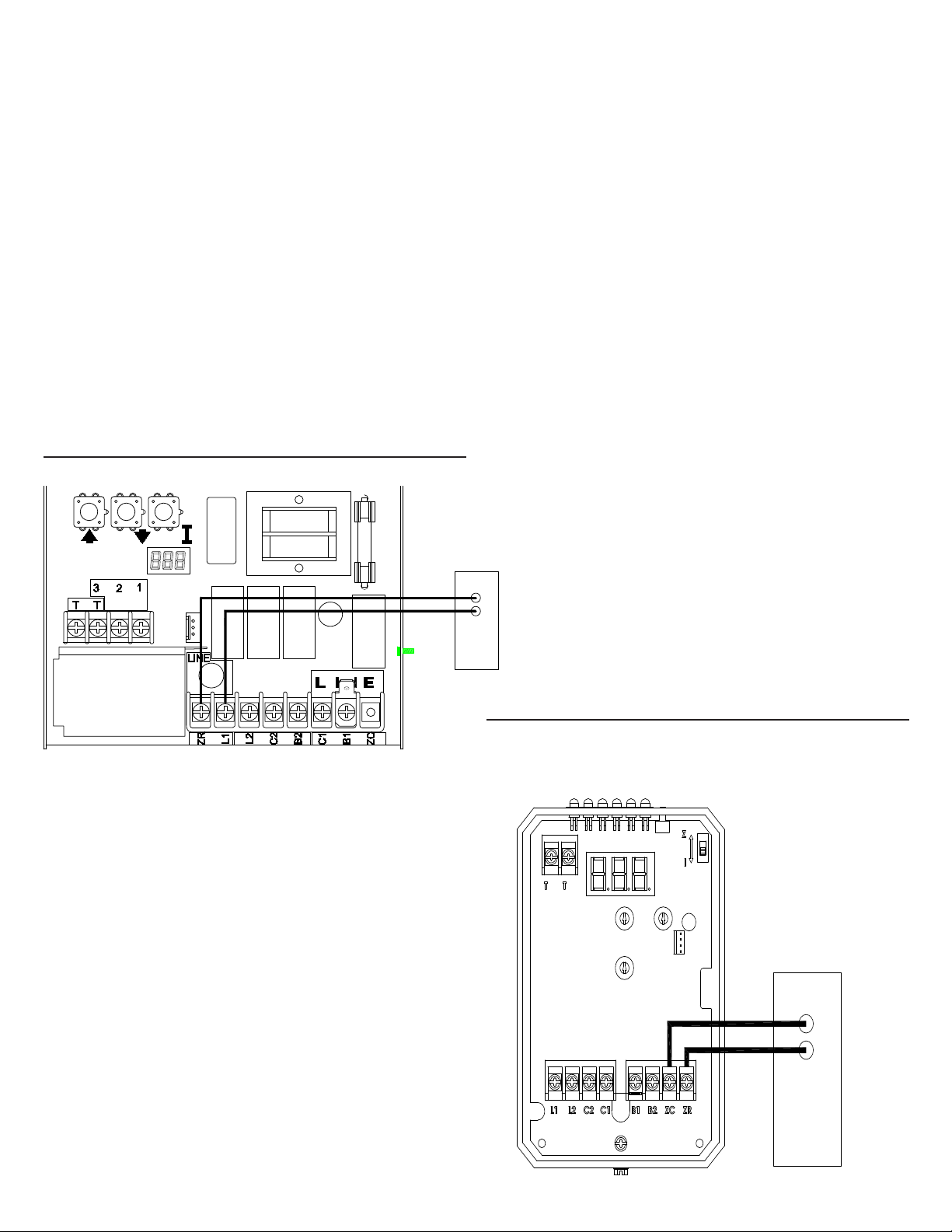
Mount low limit control on control well. Install wiring
harness per appropriate wiring diagram.
10.
Program the Control as follows:
A. Program the Honeywell L7248L Control to
recognize the L4006 Low Limit Control:
a. Press UP, DOWN and I buttons simultaneously
for three (3) seconds to enter programming
mode.
b. Press I button until "ELL" is displayed.
c. Press DOWN button until "ON" is displayed.
d. Wait 60 seconds for display to return to "BT".
B. Hydrolevel 3250 Control
a. Set the Z-I switch in the 3250 control to the I
position.
Figure 3 - Low Limit Wiring to L7248L Control
11.
Manufacturer recommended piping shown in Figure 2.
12.
Manufacturer recommends use of a tempering valve
(mixing valve).
13.
General Finish Instructions
• Resume operation using OPERATING INSTRUCTIONS
found in Installation, Operation & Maintenance Manual.
• Verify proper operation by following START UP
PROCEDURE in Installation, Operation & Maintenance
Manual.
Adjust Low Limit Control
1.
Typical set point is 140°F.
2.
Increase if hotter domestic water is desired.
3.
Low limit set point must be at least 20°F lower than
high limit set point.
L4006 LOW LIMIT
Figure 4 - Low Limit Wiring to 3250 Control
 Loading...