

dunkermotoren STA 2506P, STA 2504P, STA 2508P, STA 2510S, STA 2510P Instruction Manual
...
ServoTube 25
Type/Typ
STA 2504 STB 2504
STA 2506 STB 2506
STA 2508 STB 2508
STA 2510 STB 2510
Instruction Manual
ServoTube 25
Publication Ref: UM03011/E
Betriebsanleitung
ServoTube 25
Publikation Ref: UM03011/E

2
www.dunkermotoren.de Version 08.2017
1 Content
2 About this document 3
3 General description 4
3.1 ServoTube 25 Actuator 4
3.2 ServoTube 25 5
3.3 Standards and Guidelines 6
4 Safety instructions 7
4.1.Warning Symbols and Meanings 8
5 Technical Data 10
5.1 Electrical Specications
5.2 STA Force/Velocity Proles 11
5.3 Thermal Specications 13
5.4 Mechanical Specications 13
5.5. Position Sensor 14
5.6. Forcer Over Temperature Sensor 15
5.7 Cable 16
5.8 Connections 17
6 Installation 18
6.1 Unpacking 18
6.2 Installation 18
6.3 Mechanical Installation-STA 19
6.4 Mechanical Installation-STB 21
6.5 Electrical Installation 23
7 Maintenance & Service 24
7.1 Maintenance 24
7.2 Maintenance STA 24
7.3 Maintenance STB 24
7.4 Cable Replacement 25
7.5 Replacement 26
7.6 Service 27
7.7 Spares 27
8 Apprendices 28
8.1 Warranty 28
8.2 Troubleshooting Chart 29
8.3 Terms & Abbreviations 30
9 Service & Support 34
1 Inhalt
2 Über dieses Dokument 3
3 Allgemeine Beschreibung 4
3.1 ServoTube 25 Aktuator 4
3.2 ServoTube 25 5
3.3 Normen und Richtlinien 6
4 Sicherheitshinweise 7
4.1. Warnsymbole und Bedeutungen 8
5 Technische Daten 10
5.1 Elektrische Daten
5.2 STA Kraft/Schnelligkeit Prole 11
5.3 Thermische Daten 13
5.4 Mechanische Daten 13
5.5 Lagegeber 14
5.6 Primäreinheit Über 15
Temperatur-Sensor
5.7 Kabel 16
5.8 Verbindungen 17
6 Installation 18
6.1 Auspacken 18
6.2 Installation 18
6.3 Mechanische Installation-STA 19
6.4 Mechanische Installation-STB 21
6.5 Elektrische Installation 23
7 Wartung & Service 24
7.1 Wartung 24
7.2 Wartung STA 24
7.3 Wartung STB 24
7.4 Kabel-Austausch 25
7.5 Einbau von Einzelteilen 26
7.6 Service 27
7.7 Ersatzteile 27
8 Anhang 28
8.1 Garantie 28
8.2 Problembehandlung 29
8.3. Begriserklärungen & 30
Abkürzungen
9 Service & Support 34
3
Version 08.2017 www.dunkermotoren.com
Before commissioning, it is
essential that the safety instructions
in the relevant section are read,
understood and then observed
Non-observance can result in danger
to persons or damage to the machine.
► Disconnect the electrical power
supply!
Vor der Inbetriebnahme sind unbe dingt die Sicherheitshinweise zu lesen
und zu beachten! Eine Nichtbeach tung kann zu Gefahren bei Personen
oder Beschädigungen an der
Maschine führen.
► Gerät spannungsfrei
schalten !
WARNUNG
WARNING
Lesen und befolgen Sie in diesem
Dokument die Warnhinweise
sorgfältig. Die Warnhinweise sollen
Sie vor Gefahr schützen oder helfen
Ihnen eine Beschädigung des
Gerätes zu vermeiden.
HINWEIS
Read and observe the warnings in this
document. Warnings are there
to protect you from danger, and to
help you to avoid damage to
the device.
NOTICE
Hinweise erläutern Ihnen Vorteile
bestimmter Einstellungen und helfen
Ihnen den optimalen Nutzen aus dem
Gerät zu ziehen.
HINWEIS
Instructions explain the advantages of
certain settings and help you use the
device to the best possible eect.
NOTICE
2 Über dieses Dokument
Die vorliegende Betriebsanleitung stellt Ihnen den
ServoTube 25 vor und informiert Sie über alle Schritte
zur Installation des Antriebs und zur Durchführung von
Funktionstests.
Relevante Publikationen
Die folgenden Publikationen sind relevant für die Betriebsanleitung des ServoTube 25 Motors:
- ServoTube 25 Anwendungshandbuch
- STA Datenblatt
- STB Datenblatt
- SBA25 Datenblatt
2 About this Document
These operating instructions introduce you to the ServoTube 25 and provide you with information on all the
stages required for the installation of the drive and the
performance of functional tests.
Asscociated Publications
The following publications are associated with the
ServoTube 25 User Manual:
- ServoTube 25 Applications Guide
- STA Data sheet
- STB Data sheet
- SBA25 Data sheet
4
www.dunkermotoren.de Version 08.2017
3 Allgemeine Beschreibung
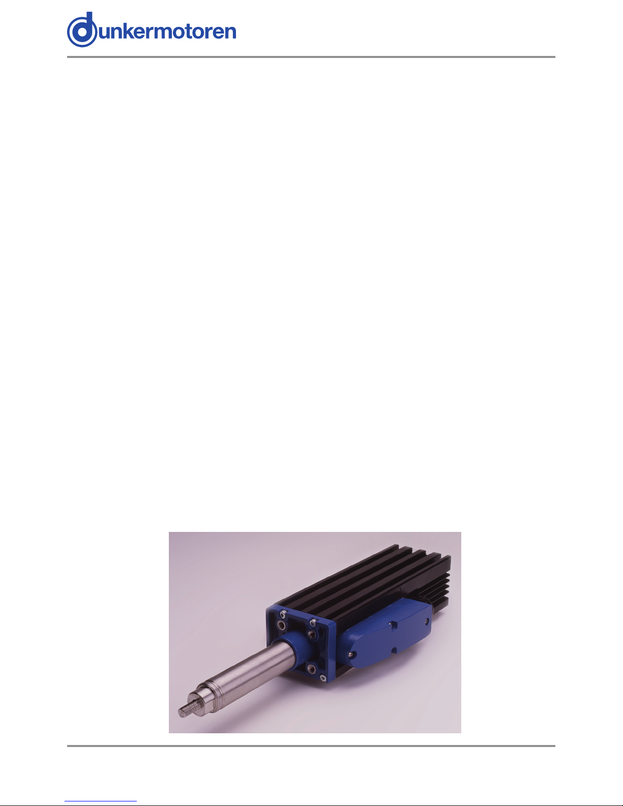
3.1 ServoTube 25 Aktuator (STA)
Der ServoTube 25 Aktuator ist eine optimale Lösung
für die industrielle Positionieranwendung. Schneller
als eine Kugelumlaufspindel und mit der absoluten Zuverlässigkeit eines Linearmotors, ist ServoTube 25 in
Applikationen, bei denen größte Flexibilität und Positioniergenauigkeit gefragt ist, eine kostengünstige Alternative zu Pneumatikzylindern.
Vier Baugroessen: Der ServoTube 25 Aktuator beinhaltet eine IP67 Primäreinheit und eine abgedichtete
Magnetstange (Seltenerdmagnete) aus rostfreiem
Stahl. Vier Baugrößen liefern einen durchgängigen
Schubkraft-Bereich von 51~102 N (11~23 lb) mit Spitzen- Schubkräften bis 780 N (175 lb). Zwölf Hublängen von 27~309 mm sind erhältlich (weitere Hublängen auf Anfrage).
Das patentierte Design von ServoTube 25 Aktuatoren
liefert eine Wiederholgenauigkeit von 12 μm und eine
Auösung von 350 μm unter Verwendung eines be-
rührungslosen, integrierten Lagegebers. Kein externer
Geber wird benötigt. Der Lagegeber gibt ein Industriestandard 1Vpk-pk sin/cos Signal aus.
Wartungsfrei: Die XTA Baureihe hat ein integriertes Trockenlager, das für eine saubere, ruhige und
wartungsfreie Performance sorgt. Die Lebensdauer
übersteigt die von Kugelumlaufspindel-Lösungen
bei weitem. Der ServoTube 25 Aktuator eignet sich
hervorragend für Push/Pull und Hebebetrieb in den
Bereichen Material Handling, Verpackung und Fertigungsautomation. Die mechanische Integration des
Aktuators kann mit Standard-Industriekomponenten
erfolgen.
3 General description
3.1 ServoTube 25 Actuator (STA)
The ServoTube 25 Actuator is an optimal solution for
industrial position control. Faster than a ballscrew with
the clean reliability of a linear forcer, ServoTube is a
cost- eective alternative to air cylinders in applications
requiring greater exibility and control.
Four Models: The ServoTube Actuator incorporates
an IP67 rated forcer and a sealed stainless steel
thrust rod enclosing rare-earth magnets. Four models
deliver a continuous force range of 51~102 N (11~23
lb) with peak forces up to 780 N (175 lb). Twelve
stroke lengths are available from 27~309 mm (other
stroke lenghts on request).
The patented magnetic design of ServoTube 25 generates 12 micron repeatability and 350 micron accuracy
from a non- contact, integral position sensor. No external encoder is required. Position output is industry
standard 1V pk-pk sin/cos signals.
Maintenance Free: An internal dry bearing provides
clean, quiet, maintenance-free performance. Life expectancy far exceeds typical ballscrew solutions.
The ServoTube Actuator is ideal for push/pull/lift material handling, packaging and automated assembly applications. ServoTube 25 accepts a range of industry
standard accessories for simple mechanical integration.

5
Version 08.2017 www.dunkermotoren.com
3.2 ServoTube 25 (STB)
ServoTube 25 liefert die Geschwindigkeit eines Riemenantriebsystems mit der sauberen Zuverlässigkeit
eines Linearmotors zu einem Preis, der beispiellos für
diese Branche ist. Ein vertrauter Formfaktor, integrierte
Positionssensoren und ein großer Luftspalt vereinfachen die Installation.
Die ServoTube 25 Linearmotor Komponenten bestehen aus einer IP67 Primäreinheit und einer abgedichteten Magnetstange aus rostfreiem Stahl, die Seltenerdmagneten umschließt. Vier Baugrößen liefern einen
durchgängigen Schubkraft-Bereich von 51-102 N (1123 lb) mit der Spitzen-Schubkraft von 780 N (175 lb).
Eine Reihe von Magnetstangen (Seltenerdmagnete)
sind erhältlich für Längen bis zu 1200 mm.
Das patentierte Design von ServoTube 25 Aktuatoren
liefert eine Wiederholgenauigkeit von 12 μm und eine
absolute Genauigkeit von 350 μm unter Verwendung
eines berührungslosen, integrierten Lagegebers. Kein
externer Geber wird benötigt. Der Lagegeber gibt ein
Industriestandard 1Vpk-pk sin/cos Signal aus.
Einfache Integration: Der ServoTube 25 ist eine
ideale OEM-Lösung zur einfachen Integration in Pick
und Place Vorrichtungen und allgemeinen Sondermaschinen. Die Last wird direkt an die Primäreinheit
befestigt und in der Regel durch eine einzige Lagerschiene gelagert. Die Magnetstange wird beidseitig
von Montagebügeln gehalten, ähnlich wie bei Kugelumlaufspindeln. Durch den großen Luftspalt muss
der Antrieb nicht aufwändig ausgerichtet werden. Die
Primäreinheit hat einen hervorragenden thermischen
Wirkungsgrad und strahlt die Wärme gleichmäßig ab.
Hohe Einschaltdauer ist möglich ohne den Einsatz von
Wasserkühlung oder Zwangslüftung.
3.2. ServoTube 25 (STB)
ServoTube 25 delivers the speed of a belt-drive system
with the clean reliability of a linear motor at a price
unprecedented in the industry. Familiar form factor,
integral position feedback and large air gap make
installation simple.
The ServoTube 25 motor components comprise an
IP67 rated forcer and a sealed stainless steel thrust
rod enclosing rare-earth magnets. Four models deliver
a continuous force range of 51-102 N (11-23 lb) with
peak forces up to 780 N (175 lb). A range of Thrust
Rods are available for travel lengths up to 1200 mm.
The patented magnetic design of ServoTube 25
generates 12 micron repeatability and 350 micron
accuracy from a non-contact, integral position sensor.
No external encoder is required. Position output is
industry standard 1V pk-pk sin/cos signals.
Easy Integration: ServoTube 25 is an ideal
OEM solution for easy integration into pick-andplace gantries and general purpose material handling
machines. The load is mounted directly to the Forcer
typically supported by a single bearing rail. The Thrust
Rod is mounted at both ends, similar to a ballscrew.
A large air gap reduces alignment constraints.
The tubular motor has superior thermal eciency,
radiating heat uniformly. High duty cycles are possible
without the need for forced-air or water cooling.

6
www.dunkermotoren.de Version 08.2017
3.3 Normen und Richtlinien
EG-Richtlinien: Die EG-Richtlinien formulieren die
Mindestanforderungen an ein Produkt und müssen von
allen Herstellern und Händlern beachtet werden, die
das Produkt in den Mitgliedstaaten der Europäischen
Union auf den Markt bringen.
Maschinenrichtlinie: Der Antrieb ist eine Maschine im
Sinne der EG-Richtlinie für Maschinen. Er hat zweckgerichtet bewegliche Teile, darf aber nur als Bestandteil
einer Maschine oder Anlage eingesetzt werden. Die in
dieser Betriebsanleitung beschriebenen Hinweise zur
Installation und Inbetriebnahme müssen
beachtet werden.
EMV-Richtlinie: Die EG-Richtlinien für EMV gelten für
Geräte, die elektromagnetische Störungen verursachen können oder deren Betrieb durch diese Störungen
beeinträchtigt werden kann. Die Übereinstimmung des
Antriebs mit der EMV-Richtlinie kann erst nach dem
Einbau überprüft werden. Die in dieser Betriebsanleitung beschriebenen Angaben zur EMV müssen beachtet werden.
Konformität: Mit der Konformitätserklärung des
Produkts bescheinigt Dunkermotoren, dass der Antrieb
den dort aufgeführten Normen zur Sicherheit und EMV
entspricht. Das Produkt darf in der Europäischen Union
vertrieben und eingesetzt werden.
3.3 Standards and Guidelines
EU guidelines: the EU guidelines formulate the mini-
mum requirements made on a product and must be observed by all manufacturers and dealers marketing the
product in the member states of the European Union.
Machine guideline: the drive is a machine in the sense of the EU guideline for machinery. It has moveable parts in accordance with its intended purpose: however, it may only be installed as a component of a
machine or a system. The advice described in these
instructions regarding installation and operation must
be adhered to.
EMC guideline: the EU guidelines for EMC apply to
devices which can cause electromagnetic interruptions
or whose operation can be impaired by these interruptions. Compliance of the drive with the EMC guideline
can only be tested once it has been installed. The information pertaining to EMC described in these instructions must be adhered to.
Conformity: by means of the conformity declaration
of the product, Dunkermotoren conrms that the drive
complies with the safety standards listed there in and
with EMC standards. The product may be sold and
used within the European Union.
7
Version 08.2017 www.dunkermotoren.com
Before commissioning, it is
essential that the safety instructions
in the relevant section are read,
understood and then observed
Non-observance can result in danger
to persons or damage to the machine.
► Disconnect the electrical power
supply!
Vor der Inbetriebnahme sind unbe dingt die Sicherheitshinweise zu lesen
und zu beachten! Eine Nichtbeach tung kann zu Gefahren bei Personen
oder Beschädigungen an der
Maschine führen.
► Gerät spannungsfrei
schalten !
WARNUNG
WARNING
Die Antriebe dürfen nur von
qualiziertem Personal nach den
entsprechenden Normen eingebaut
und eingerichtet werden.
Als qualiziert gilt eine Person dann,
► wenn ihre Erfahrung mögliche Gefahren
vermeiden kann.
► wenn ihr die Unfallverhütungsvor-
schriften bekannt sind.
► wenn sie gemäß den Normen Stromkreise
und Geräte in Betrieb setzen und
installieren darf.
HINWEIS
The drive must only be installed
and adjusted by qualied persons
in accordance with the relevant
standards.
Qualied persons are those who:
► on the basis of their experience, can
recognise and avoid potential dangers.
► are familiar with the accident-prevention
regulations for the equipment deployed.
► are able to connect circuits and install
equipment in accordance with the
standards and regulations.
NOTICE
Der störungsfreie Betrieb setzt
entsprechende Lagerung und
Transport nach den entsprechenden
Vorgaben voraus.
Lagern Sie bitte den Antrieb geschützt vor:
► Staub, Schmutz und Feuchtigkeit!
Achten Sie auch auf die Lagerbedingungen:
► z.B. Lagerungstemperatur!
(Siehe technische Daten)
Transportieren Sie die Antriebe unter
Lagerbedingungen:
►
stoßgeschützt
HINWEIS
To ensure trouble-free operation,
appropriate methods of transport and
conditions of storage must be
deployed.
Please store the drive so that it is protected from:
► dust, dirt and moisture!
Take care also at the storage conditions:
► e.g. storage temperature!
(See technical data)
Transport the drive under storage
conditions
► protection against shock
NOTICE
4 Safety instructions
4 Sicherheitshinweise
8
www.dunkermotoren.de Version 08.2017
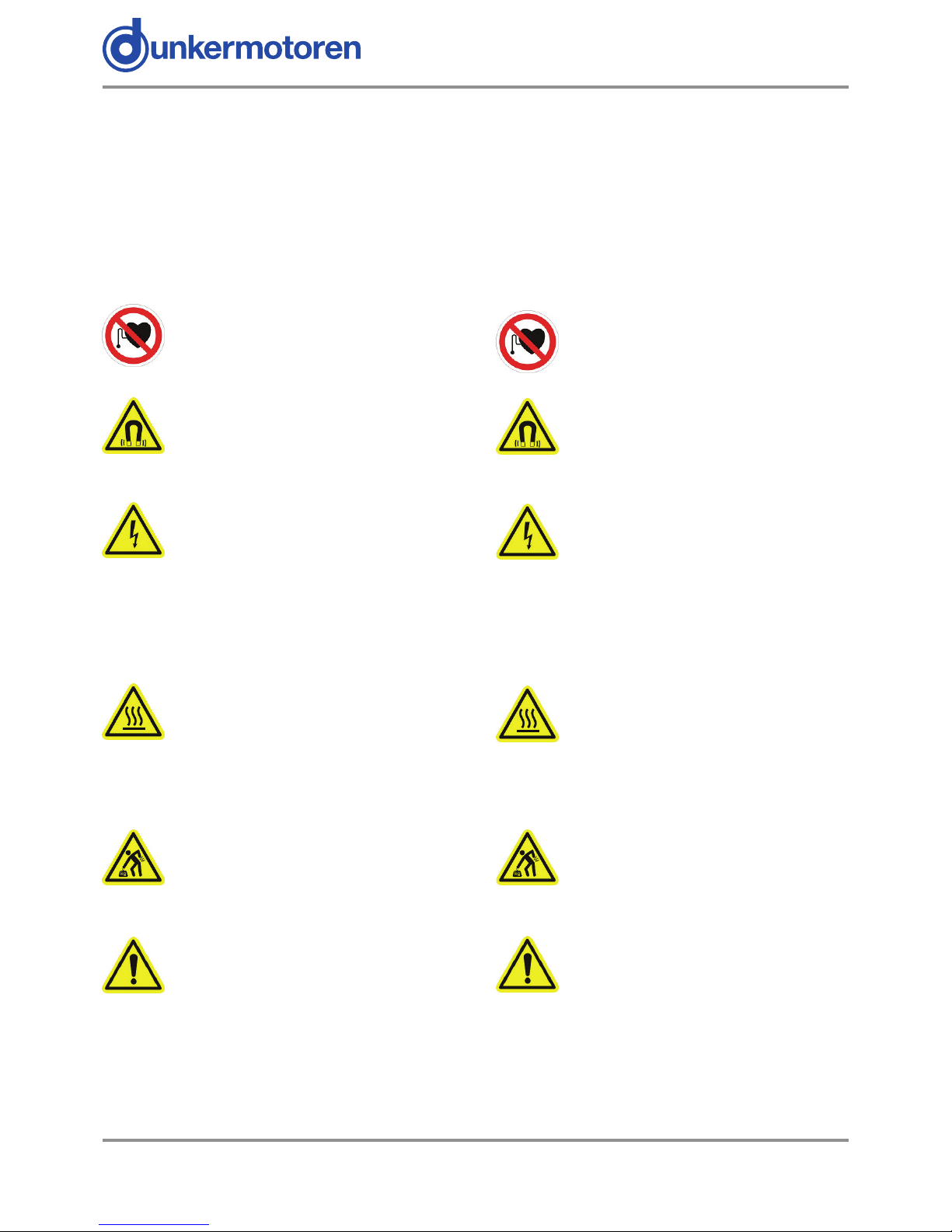
4.1 Warnsymbole und Bedeutungen
In der vorliegenden Betriebsanleitung werden die unten aufgelisteten Warnsignale verwendet. Bitte lesen
und befolgen Sie diese sorgfältig. Die Warnsignale sollen Sie vor möglichen Gefahren schützen, die mit dem
beschriebenen Equipment in allen Bereichen der Verwendung, Steuerung, Installation, Inbetriebnahme und
Wartung auftreten könnten.
Herzschrittmacher: Mitarbeiter mit Herzschrittmachern dürfen nicht mit dem Gerät
arbeiten.
Achtung starke Magnete: Die Magnetstange enthält starke Magnete, die eisenhaltige Objekte stark anziehen. Computer
Disks und Kreditkarten können Schaden
nehmen.
Achtung Lebensgefahr durch Stromschlag: Potentiell lebensgefährliche
Stromschläge können während der Inbe-
triebnahme und Wartung des Geräts auftreten. Wenn Sie dieses Zeichen sehen, dann prüfen
Sie stets ob das Gerät spannungsfrei und gegen versehentliches Einschalten gesichert ist. Besondere Vorsicht gilt bei der Arbeit an oder in der Nähe von der
Stromversorgung.
Heiße Oberäche. Oberächentempera-
turen von bis zu 80 °C können während
der Inbetriebnahme und Wartung des Mo-
tors auftreten. Stellen Sie sicher, dass Primäreinheit und Magnetstange stets herunter gekühlt
sind bevor Sie mit den Arbeiten am Gerät beginnen.
Quetschgefahr: Die Primäreinheit könnte
sich unvorhergesehen Bewegen. Prüfen
Sie stets, dass das Gerät spannungsfrei
ist bevor Sie beginnen daran zu arbeiten.
Gefahr! Befolgen Sie die Sicherheitshin-
weise.
Elektrische Schutzmaßnahmen
Das Gerät muss mit Hilfe des grün/gelben elektrischen
Erdungsleiters geerdet werden.
4.1 Warning Symbols and Meanings
In this User Manual warning symbols are used. These
are intended to alert you to the potential hazards to
personnel which are associated with the equipment
described, in all aspects of use, including handling,
installation, operation and maintenance.
Heart pacemakers: Personnel tted with
pacemakers must not handle or work on
this equipment.
Strong magnets: The thrust rod contains
powerful magnets and will strongly attract
ferrous objects. Damage can occur to
computer disks and credit cards.
Electric shock. Potentially lethal voltages
may be present during the commissioning
and servicing of this equipment. Isolate and
disconnect all sources of electrical supply
before working on the equipment. Particular care needs
to be taken when working on or around motor phase
connections.
Hot surface. Surface temperatures of up
to 80 °C can be present during the
commissioning and servicing of this
equipment. Allow the forcer and thrust rod
to cool before working on the equipment.
Crush hazard. The forcer may move
unexpectedly. Always isolate all sources of
electrical supply before working on the
equipment.
General hazard. Follow the advice given.
Electrical safety
This equipment must be earthed using the green/
yellow conductor.

9
Version 08.2017 www.dunkermotoren.com
4.1 Warning symbols and meanings
EMC precautions: This equipment is intended for
use in a light industrial environment. It is recommended
that the following precautions be observed during
installation:
• Keep all cable lengths to a minimum.
• Provide as much physical separation as possible
between power and signal cables. In particular,
avoid long, parallel runs of cables.
• Maintain screen continuity throughout the cable
run.
• Use 360 degree screen terminations where
possible. “Pig-tail” terminations are not
recommended.
It is the responsibility of the User to ensure compliance
with any local electrical and EMC regulations in force at
the time of installation.
4.1 Warnsymbole und Bedeutungen
EMC Sicherheitsvorkehrungen: Das Gerät ist für
eine Verwendung in einer Leichtindustrieumgebung
vorgesehen. Es wird empfohlen, dass die folgenden
Sicherheitsvorkehrungen während der Inbetriebnahme
befolgt werden:
• Halten sie alle Kabel auf möglichst minimalen Läng en
• Stellen Sie sicher, dass so viel räumlicher Abstand
wie möglich zwischen Leistung-und Signalkabeln
besteht.
• Sorgen Sie für einen durchgängigen Kabelschirm
über die gesamte Kabellänge.
• Legen Sie den Schirm, wenn möglich, über 360˚ auf.
„Kabelschwanz“ Abschlüsse werden nicht emp fohlen.
Der Benutzer ist verantwortlich zur Gewährleistung
der Übereinstimmung mit lokal bindenden Strom-und
EMV Bestimmungen, die zum Zeitpunkt der Installation geltend sind.

10
www.dunkermotoren.de Version 08.2017
5.Technical Data
5.1 Electrical specication
5. Technische Daten
5.1 Motorspezikationen
Notes/Anmerkungen
(1) S=series forcer phases, P=parallel forcer phases/ S= Phasen der Primäreinheit in Serie, P= Phasen der Primäreinheit parallel, (2) Reduce continuous stall force to
89% at 40°C ambient/ Bei 40°C Dauer-Startkraft auf 89% reduzieren, (3) Based on a 27 mm stroke/ Bedingung: Bewegende Magnetstange mit 27 mm Hub Nutzlast,
(4) Based on triangular move over maximum stroke and no payload/ Bedingung: Bewegende Magnetstange mit Dreiecksbewegung über den maximalen Hub, (5)
Based on a moving forcer and no playload/ Bedingung: Bewegende Magnetstange und keine Nutzlast
FORCER TYPE/Primäreinheit 2504 2506 2508 2510
units/Einheiten
S (1) P (1) S (1) P (1) S (1) P (1) S (1) P (1)
Peak force @ 25
o
C ambient for 1 sec/Spitzen-
Schubkraft @ 25˚C Umgebung, Dauer: 1s
312 156 468 234 624 312 780 390
N
Peak current @ 25
o
C ambient for 1 sec/
Spitzenstrom @ 25˚C Umgebung, Dauer: 1s
20 20 20 20 20 20 20 20
A
pk
With 25 x 25 x 2.5 cm heatsink plate/
Mit 25 x 25 x 2,5 cm Kühlkörperplatte
Continuous stall force @ 25
o
C ambient (2)/
Dauerkraft @ 25˚C Umgebung (2)
51.2 51.2 69.5 69.5 86.4 86.4 102.4 102.4
N
Continuous stall current @ 25
o
C ambient/
Dauerstrom @ 25˚C Umgebung
2.31 4.62 2.10 4.20 1.96 3.92 1.86 3.72
A
rms
3.27 6.54 2.97 5.94 2.77 5.54 2.62 5.24
A
pk
Without heatsink plate/Ohne Kühlkörperplatte
Continuous stall force @ 25
o
C ambient (2)/
Dauerkraft @ 25˚C Umgebung (2)
42.5 42.5 59.5 59.5 75.1 75.1 90.0 90.0
N
Continuous stall current @ 25
o
C ambient/
Dauerstrom @ 25˚C Umgebung
1.92 3.84 1.80 3.60 1.70 3.40 1.63 3.26
A
rms
2.72 5.44 2.54 5.08 2.41 4.82 2.31 4.62
A
pk
Force constant (sine commutation)/
Kraftkonstante (Sinuskommutierung)
22.1 11.0 33.1 16.5 44.1 22.0 55.2 27.6
N/A
rms
15.6 7.8 23.4 11.7 31.2 15.6 39.0 19.5
N/A
pk
Back EMF constant (phase to phase)/GegenEMK Konstante (Phase-Phase)
18.0 9.0 27.0 13.5 36.0 18.0 45.0 22.5
V
pk
/m/s
Fundamental forcer constant/Grundkonstante
Priäreinheit
6.47 6.47 7.92 7.92 9.13 9.13 10.24 10.24
N/√ W
Eddy current loss/Wirbelstromverlust 9.51 9.51 12.55 12.55 15.58 15.58 18.61 18.61
N/m/s
Resistance @ 25
o
C (phase to phase)/
Widerstand @ 25˚C (Phase-Phase)
6.02 1.50 9.02 2.25 12.03 3.01 15.04 3.76
Ohm
Resistance @ 100
o
C (phase to phase)/
Widerstand @ 100˚C (Phase-Phase)
7.75 1.94 11.63 2.91 15.51 3.88 19.39 4.85
Ohm
Inductance @ 1kHz (phase to phase)/
Induktivität @ 1kHz (Phase-Phase)
3.90 0.97 5.85 1.46 7.80 1.95 9.75 2.44
mH
Electrical time constant/Elektrische
Zeitkonstante
0.65 0.65 0.65 0.65 0.65 0.65 0.65 0.65
ms
Continuous working voltage/Dauer
Betriebsspannung
380 380 380 380 380 380 380 380
V d.c.
Pole pitch (one electrical cycle)/Polabstand (ein
elektr. Zyklus)
51.2 51.2 51.2 51.2 51.2 51.2 51.2 51.2
mm
STA Peak acceleration (3)/STA
Spitzenbeschleunigung (3)
394 197 483 241 542 271 586 293
m/s
2
STA Maximum speed (4)/STA
Maximalgeschwindigkeit (4)
5.9 4.4 5.3 5.1 4.7 5.6 4.2 5.8
m/s
STB Peak acceleration (5)/STB
Spitzenbeschleunigung (5)
223 111 223 111 235 117 256 128
m/s
2
STB Maximum speed (4)/
Maximalgeschwindigkeit (4)
8.7 7.3 6.5 7.2 5.4 7.6 4.6 7.0
m/s
11
Version 08.2017 www.dunkermotoren.com
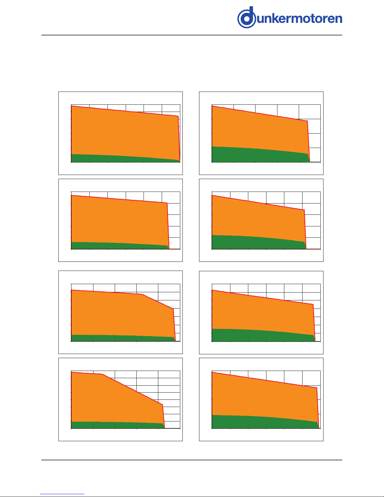
5.2 STA FORCE /VELOCITY PROFILES 5.2 STA KRAFT/GESCHWINDIGKEITSPROFILE
(WITH AN OPERATING VOLTAGE OF 325 VD.C.) (MIT EINER BETRIEBSSPANNUNG VON 325 VD.C.)
S=series forcer phases S=Seriale Phasen der Primäreinheit
P=parallel forcer phases P=Parallele Phasen der Primäreinheit
STA2504S force/velocity
PEAK
CONTINUOUS
0
40
80
120
160
200
240
280
320
0 1 2 3 4 5 6
Velocity (m/s)
Force (N)
STA2504P force/velocity
PEAK
CONTINUOUS
0
40
80
120
160
0 1 2 3 4 5
Velocity (m/s)
Force (N)
STA2506S force/velocity
PEAK
CONTINUOUS
0
100
200
300
400
500
0 1 2 3 4 5 6
Velocity (m/s)
Force (N)
STA2506P force/velocity
PEAK
CONTINUOUS
0
50
100
150
200
250
0 1 2 3 4 5 6
Velocity (m/s)
Force (N)
STA2508S force/velocity
PEAK
CONTINUOUS
0
100
200
300
400
500
600
700
0 1 2 3 4 5
Velocity (m/s)
Force (N)
STA2508P force/velocity
PEAK
CONTINUOUS
0
50
100
150
200
250
300
350
0 1 2 3 4 5 6
Velocity (m/s)
Force (N)
STA2510S force/velocity
PEAK
CONTINUOUS
0
100
200
300
400
500
600
700
800
0 1 2 3 4 5
Velocity (m/s)
Force (N)
STA2510P force/velocity
PEAK
CONTINUOUS
0
100
200
300
400
0 1 2 3 4 5 6
Velocity (m/s)
Force (N)
 Loading...