

dunkermotoren BGE 6e, BGE 4811 Operating Manual
BGE 4811 / BGE 6e
Typ: Part No:
BGE 4811 88740 011XX
Operating Manual BGE 4811 / BGE 6e
Publication Ref: 160122
Betriebsanleitung BGE 4811 / BGE 6e
Publikation Ref: 160122
BGE 6e 88720 018XX
BGE 6e
Dunkermotoren GmbH | Allmendstraße 11 | D-79848 Bonndorf/ Schwarzwald
Phone +49 (0) 7703 930-0 | Fax +49 (0) 7703 930-210/ 212 | info@dunkermotoren.com
BGE 4811
Version 12/2017

Content
2 About this document ��������������������������������� 6
3 General description ����������������������������������� 7
3.1 BGE 4811 / BGE 6e ................................. 7
Inhalt
2 Über dieses Dokument������������������������������ 6
3 Allgemeine Beschreibung ������������������������ 7
3.1 BGE 4811 / BGE 6e ................................. 7
3.2 BGE 6e ................................................... 7
3.3 BGE 4811 ................................................ 7
4 Technical data �������������������������������������������� 8
4.1 Electrical data .......................................... 8
4.2 Mechanical data ....................................... 8
4.3 Dimensions ............................................. 9
4.3.1 Dimensions BGE 6e ................................ 9
4.3.2 Dimensions BGE 4811 ........................... 10
4.4 Pin assignment ...................................... 10
5 Installation������������������������������������������������ 13
5.1 Mechanical Installation ............................13
5.2 Electrical Installation ................................13
5.2.1 Electro-magnetic compatibility ..................13
5.2.2 Ground wire ..........................................13
5.2.3 Schematic circuit of the digital inputs .........14
5.3 Analog inputs ..........................................14
5.3.1 Function analog input .............................14
5.3.2 Schematic circuit of the analog input ..........15
5.4 Digital outputs .........................................15
3.2 BGE 6e ................................................... 7
3.3 BGE 4811 ................................................ 7
4 Technische Daten �������������������������������������� 8
4.1 Elektrische Daten ..................................... 8
4.2 Mechanische Daten ................................. 8
4.3 Abmessungen .......................................... 9
4.3.1 Abmessung BGE 6e ................................ 9
4.3.2 Abmessung BGE 4811 ........................... 10
4.4 Pin Belegung ......................................... 10
5 Installation������������������������������������������������ 13
5.1 Mechanische Installation .........................13
5.2 Elektrische Installation .............................13
5.2.1 Elektromagnetische Verträglichkeit ............13
5.2.2 Erdung ................................................13
5.2.3 Prinzipschaltung der Digitaleingänge .........14
5.3 Analoge Eingänge ...................................14
5.3.1 Funktion analoger Eingang ......................14
5.3.2 Prinzipschaltung Analogeingang ...............15
5.4 Digitale Ausgänge ...................................15
5.4.1 Function digital outputs ...........................15
5.4.2 Schematic circuit of the digital outputs ........15
6 BGE 6e ������������������������������������������������������ 16
6.1 Power supply ......................................... 16
6.2 I/O-Connector ........................................ 16
6.3 Bus-Connector ........................................17
6.4 Alternative-connector for single internal
conguration ...........................................17
6.5 Schematic/ power supply BGE 6e ............18
7 BGE 4811 �������������������������������������������������� 19
7.1 Power supply ..........................................19
7.2 I/O-Connector .........................................19
7.3 Bus-Connector ....................................... 20
7.4 Alternative-connector for single internal
conguration .......................................... 20
7.5 Motor phases ......................................... 21
7.6 Hall signals and attachment .................... 21
5.4.1 Funktion digitale Ausgänge ......................15
5.4.2 Prinzipschaltung der Digitalausgänge ........15
6 BGE 6e ������������������������������������������������������ 16
6.1 Leistungsversorgung .............................. 16
6.2 I/O-Stecker ............................................ 16
6.3 Bus-Stecker ............................................17
6.4 Alternativ-Stecker solo für
Eigenkonguration ..................................17
6.5 Schaltbild Spannungsvers. BGE 6e ..........18
7 BGE 4811 �������������������������������������������������� 19
7.1 Leistungsversorgung ...............................19
7.2 I/O-Stecker .............................................19
7.3 Bus-Stecker ........................................... 20
7.4 Alternativ-Stecker solo für
Eigenkonguration ................................. 20
7.5 Motorphase ........................................... 21
7.6 Hallsignale und Anbauten ....................... 21
Version 12.2017 | Page/ Seite 2 www.dunkermotoren.com

7.7 Alternative-connector for single internal
conguration .......................................... 22
7.7 Alternativ-Stecker solo für
Eigenkonguration ................................. 22
7.8 Schematic/ power supply BGE 4811 ........ 22
8 SI operating modes ��������������������������������� 24
8.1 SI Vel-Mode ........................................... 24
8.2 Indicators/ Potentiometers ...................... 24
8.3 Control functions .................................... 25
8.4 Speed target value & current limitation ..... 25
8.5 Saving to the EEPROM .......................... 26
9 Position mode ������������������������������������������ 27
9.1 Position Mode ........................................ 27
9.2 Control functions .................................... 27
9.3 Homing ................................................. 28
9.4 Quick stop ............................................. 28
10 XI Modus funtionality ���������������������������� 29
10.1 Supported DSP 402 modes of operation 29
10.2 Velocity and positioning
feedback ............................................. 30
7.8 Schaltbild Spannungsvers. BGE 4811 ...... 22
8 SI Betriebsarten ��������������������������������������� 24
8.1 SI Drehzahl Modus ................................. 24
8.2 Statusanzeige/ Potentiometer ................. 24
8.3 Kontrollfunktionen .................................. 25
8.4 Drehzahlsollwert & Strombegrenzung ...... 25
8.5 Speichern in EEPROM ........................... 26
9 Positionier Modus ����������������������������������� 27
9.1 Positionier Modus .................................. 27
9.2 Kontrollfunktionen .................................. 27
9.3 Homing ................................................. 28
9.4 Schnellstopp .......................................... 28
10 XI Modus Funktionalität ������������������������ 29
10.1 Unterstüzte Betriebsarten DSP 402 ....... 29
10.2 Geschwindigkeits- und Positionsrück-
meldung .............................................. 30
10.2.1 HALL sensor feedback ......................... 30
10.2.2 Encoder feedback ............................... 30
10.3 Brake management ...............................31
10.4 Communication .....................................31
10.5 Communication through the
mapped registers ................................. 32
10.6 Communication through the
encapsulated messages (MEI) .............. 33
11 Protection functions ������������������������������ 34
11.1 Over temperature ................................. 34
11.2 Under voltage logic supply .................... 34
11.3 Under voltage power supply .................. 34
11.4 Over voltage logic supply ...................... 34
11.5 Over voltage power supply .................... 34
11.6 Over current (I²t) ................................... 35
11.7 Voltage controller braking ...................... 35
10.2.1 Hallsensor Rückführung ....................... 30
10.2.2 Geberrückführung ............................... 30
10.3 Bremsmanagement .............................. 31
10.4 Kommunikation .................................... 31
10.5 Kommunikation über die abgebildeten
Register............................................... 32
10.6 Kommunikation über eingekapselte
Nachrichten (MEI) ................................ 33
11 Schutzfunktionen ����������������������������������� 34
11.1 Übertemperatur .................................... 34
11.2 Unterspannungs- Logikversorgung ........ 34
11.3 Unterspannungs- Stromversorgung........ 34
11.4 Überspannungs- Logikversorgung ......... 34
11.5 Überspannungs- Stromversorgung ........ 34
11.6 Überstrom (I2t) ...................................... 35
11.7 Spannungsgeregeltes Bremsen ............. 35
11.8 Overview of protection thresholds .......... 35
11.9 Indicators ............................................. 36
12 Congurator ������������������������������������������� 37
13 StarterKit ������������������������������������������������ 38
13.1 Instructions for Bus ............................... 39
Version 12.2017 | Page/ Seite 3 www.dunkermotoren.com
11.8 Übersicht der Schutzschwelle ................ 35
11.9 Statusanzeige ...................................... 36
12 Kongurator ������������������������������������������� 37
13 StarterKit ������������������������������������������������ 38
13.1 Hinweise für Bus .................................. 39

13.2 Requirements ...................................... 40
13.2 Voraussetzungen ................................. 40
13.3 Introduction .......................................... 40
13.4 Documentations ................................... 40
14 Optional attachments ���������������������������� 41
14.1 BGE 6e ................................................41
14.2 BGE 4811 .............................................41
14.3 Detail Overview BGE 6e ....................... 42
14.4 Detail Overview BGE 4811 .................... 43
15 Commissioning�������������������������������������� 44
15.1 Software .............................................. 44
15.2 Hardware ............................................ 44
15.3 Initial start-up trough E-line congurator
.................................................................. 45
15.4 Start-up through a superior controller (PLC)
with Modbus .................................................47
16 Maintenance & Service ������������������������� 48
16.1 Maintenance and abandonment ............ 48
16.2 Disposal .............................................. 48
13.3 Einführung ........................................... 40
13.4 Dokumentationen ................................. 40
14 Optionale Anbauten ������������������������������ 41
14.1 BGE 6e ................................................41
14.2 BGE 4811 .............................................41
14.3 Detailansicht BGE 6e ........................... 42
14.4 Detailansicht BGE 4811 ........................ 43
15 Inbetriebnahme �������������������������������������� 44
15.1 Softwareseitig ...................................... 44
15.2 Hardwareseitig ..................................... 44
15.3 Erste Inbetriebnahme mittels E-line Kon-
gurator ........................................................ 45
15.4 Inbetriebnahme mittels einer übergeord-
neten Steuerung (PLC) über Modbus ............ 47
16 Wartung & Service ��������������������������������� 48
16.1 Wartung und Außerbetriebsetzung ......... 48
16.2 Entsorgung .......................................... 48
16.3 Service & Support ................................ 49
16.4 Scope of delivery and accessories ......... 49
16.5 Download PDF-Data ............................. 49
16.3 Service & Support ................................ 49
16.4 Lieferumfang und Zubehör .................... 49
16.5 Download PDF-Daten ........................... 49
Version 12.2017 | Page/ Seite 4 www.dunkermotoren.com

Version 12.2017 | Page/ Seite 5 www.dunkermotoren.com
2 About this document
2 Über dieses Dokument
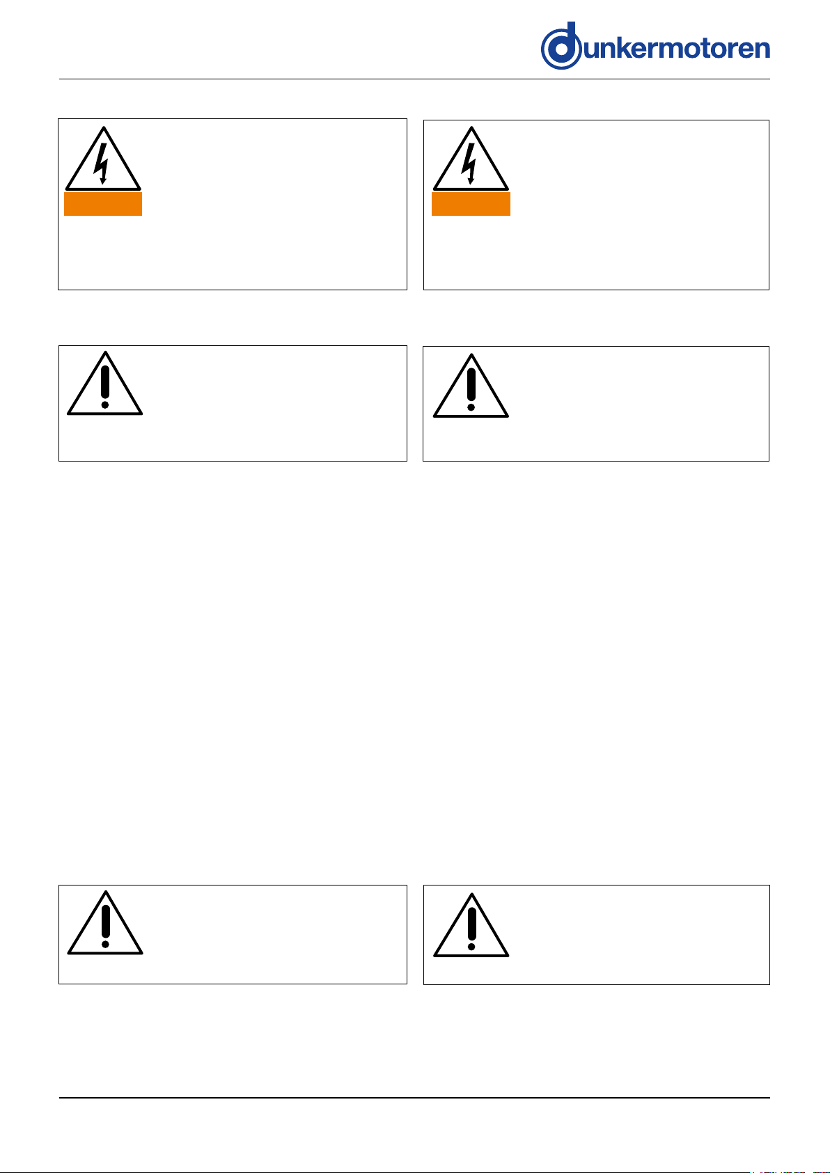
NOTICE
NOTICE
Before commissioning, it is essential
that the safety instructions in the
relevant section are read and
understood, and then observed!
Non-observance can result in danger
to persons or damage to the machine.
» Disconnect the electrical power
supply!
Read and observe the warnings in
this dokument. Warnings are there
to protect you from danger, and to
help you to avoid damage to
the device.
Instructions explain the advantages of
certain settings and help you use the
device to the best possible eect.
WARNUNGWARNING
HINWEIS
HINWEIS
Vor der Inbetriebnahme sind
unbedingt die Sicherheitshinweise zu
lesen und zu beachten!
Eine Nichtbeachtung kann zu
Gefahren bei Personen oder
Beschädigungen an der Maschine
führen.
» Gerät spannungsfrei schalten!
Lesen und befolgen Sie in diesem
Dokument die Warnhinweise
sorgfältig. Die Warnhinweise sollen
Sie vor Gefahr schützen oder helfen
Ihnen eine Beschädigung des
Gerätes zu vermeiden.
Hinweise erläutern Ihnen Vorteile
bestimmter Einstellungen und helfen
Ihnen den optimalen Nutzen aus dem
Gerät zu ziehen.
Version 12.2017 | Page/ Seite 6 www.dunkermotoren.com

3 Allgemeine Beschreibung3 General description
3�1 BGE 4811 / BGE 6e 3�1 BGE 4811 / BGE 6e
» The control electronics BGE is a 4-quadrant
controller for 3-phase BLDC motors of series
BG 6 e-line.
» The controller of the motor has a block commutation
» The controller can be parameterized via
Modbus / RS485.
» The speed target value is selected either via an
analog input or via the parameters or potentiometers.
» The field of application for this controller is amongst
the industry.
» Alternatives:
- Stand-alone mode, Speed mode, Positioning mode
or control via Modbus
3�2 BGE 6e 3�2 BGE 6e
3�3 BGE 4811 3�3 BGE 4811
» The electronic is an external electronic.
The motor BG 6 e-line is connected by a cable to
the electronic.
» Die Regelelektronik BGE ist ein 4-Quadranten-Regler
für 3-phasige BLDC Motoren der Baugröße BG 6 e line.
» Der Regler des Motors besitzt eine Blockkommutie rung
» Der Regler kann über Modbus/ RS485 parametriert
werden.
» Die Drehzahlsollwertvorgabe erfolgt wahlweise über
einen Analogeingang oder über Parameter oder
Potentiometer.
» Das Einsatzgebiet für diesen Regler ist unter ande rem die Industrie.
» Varianten:
- Betriebsart Stand-alone, Drehzahl Modus, Positi
nier Modus oder Steuerung über Modbus
» Die Regelelektronik ist am Motor BG 6 e-line montiert. » The control electronics are mounted to the BG 6 e-line.
» Die Elektronik ist eine externe Elektronik. Der Motor
BG 6 e-line ist über Kabel mit der Elektronik
verbunden.
Version 12.2017 | Page/ Seite 7 www.dunkermotoren.com
4 Technische Daten4 Technical data
Exceeding of the maximum values!
Consequence:
The controller will be destroyed�
» During the conguration of the
controller note the maximum values!
VORSICHTCAUTION
Überschreiten der Maximalwerte!
Die Folge:
Zerstörung des Reglers�
» Beim Kongurieren des Reglers die
Maximalwerte beachten!
4�1 Electrical data 4�1 Elektrische Daten
BGE 4811 / BGE 6e
Nominal voltage electronic supply/
Versorgungsspannung Elektronik
Nominal voltage power supply/
Versorgungsspannung Leistung
Permissible operating voltage range/
Zulässiger Betriebsspannungsbereich
Current consumption electronic supply/
Stromaufnahme Elektronik
Peak output current power supply/
Maximaler Ausgangsstrom (2 sec.)
Continuous output current/
Zulässiger Dauerausgangsstrom
Field bus/ Feldbus Modbus RTU over/ über RS485, two-wire/ mit zwei Drähten
VDC 24
VDC 24 ... 48
VDC 12 ... 24
mA < 100
A 30
A 10.5
Digital input/ Digitale Eingänge 5
Digital output/ Digitale Ausgänge 3
Analog input/ Analoge Eingänge 2
External encoder input/ Externer Gebereingang 4, incremental A+B, 5 V, GND
Potentiometers/ Potentiometer 2
Over temperature protection Resistance/
Übertemperaturschutz Widerstand
LEDs/ LEDs 2
External brake driving/
Max. Ausgangsstrom für Bremse
A 1
NTC 47 kΩ
4�2 Mechanical data 4�2 Mechanische Daten
BGE 4811 / BGE 6e
Protection class/
Schutzart
Ambient temperature/
Umgebungstemperatur
Dimension (LxWxH) BGE 6e without connector/
Abmessung (LxBxH) BGE 6e ohne Stecker
Dimension (LxWxH) BGE 4811/
Abmessung (LxBxH) BGE 4811
Weight BGE 6e/
Gewicht BGE 6e
Weight BGE 4811/
Gewicht BGE 4811
IP IP 30
°C 0-60
mm 81x65x48
mm 130x80x62
kg 0,3
kg 0,54
Version 12.2017 | Page/ Seite 8 www.dunkermotoren.com
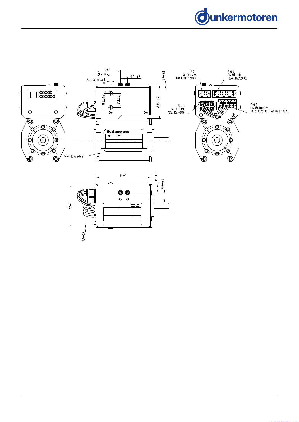
4�3 Dimensions 4�3 Abmessungen
4.3.1 Dimensions BGE 6e 4.3.1 Abmessung BGE 6e
Version 12.2017 | Page/ Seite 9 www.dunkermotoren.com
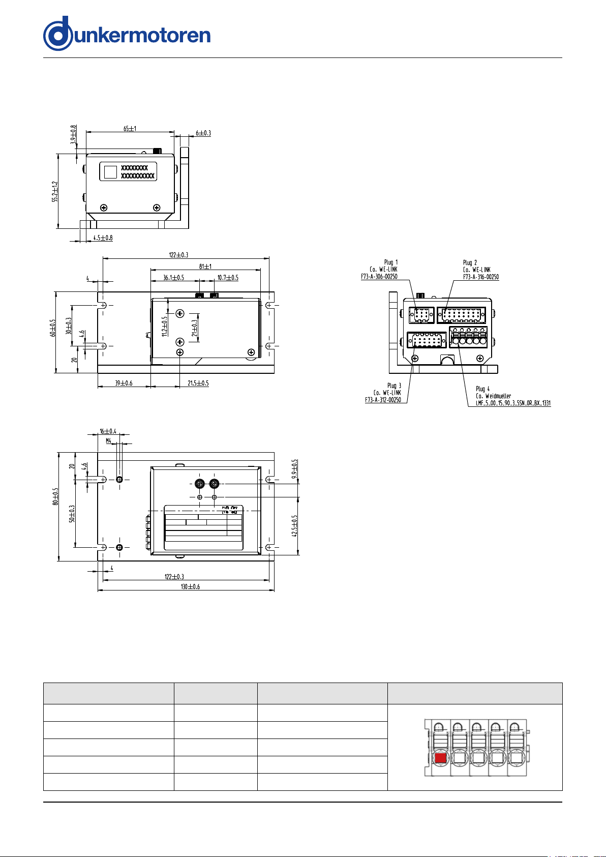
4.3.2 Dimensions BGE 4811 4.3.2 Abmessung BGE 4811
4�4 Pin assignment 4�4 Pin Belegung
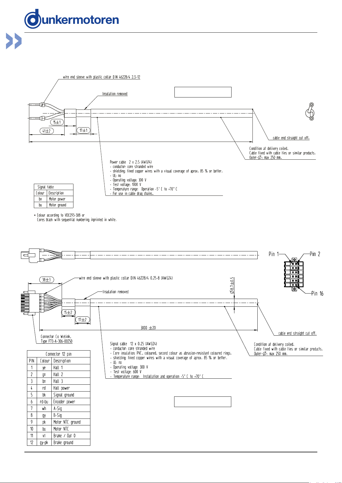
Motor and power supply
Function/ Funktion Pin Conductor color/ Leiterfarbe
Motor phase C 1 grey/ grau
Motor phase B 2 white/ weiß
Motor phase A 3 blue/ blau
Motor GND 4 black/ schwarz
Motor power 5 red/ rot
Motorphasen und Leistungsversorgung
5 pin Weidmueller connector:
LMF 5.00 05 90 3.5
PIN 1 PIN 2 PIN 3 PIN 4 PIN 5
Version 12.2017 | Page/ Seite 10 www.dunkermotoren.com
Hall signals and attachments Hallsignale und Anbauten
Function/ Funktion Pin Conductor color/ Leiterfarbe
Hall 1 1 yellow/ gelb
Hall 2 2 green/ grün
Hall 3 3 brown/ braun
Hall power +12 V 4 red/ rot
Signal GND 5 black/ schwarz
Enc power +5 V 6 -
A-Signal 7 -
B-Signal 8 -
Motor NTC GND *
Motor NTC *
1)
1)
9 -
10 -
Brake/DOUT0 11 -
Brake GND 12 -
1)
*
This function is not yet available in the software./
Diese Funktion ist noch nicht in der Software vorhanden.
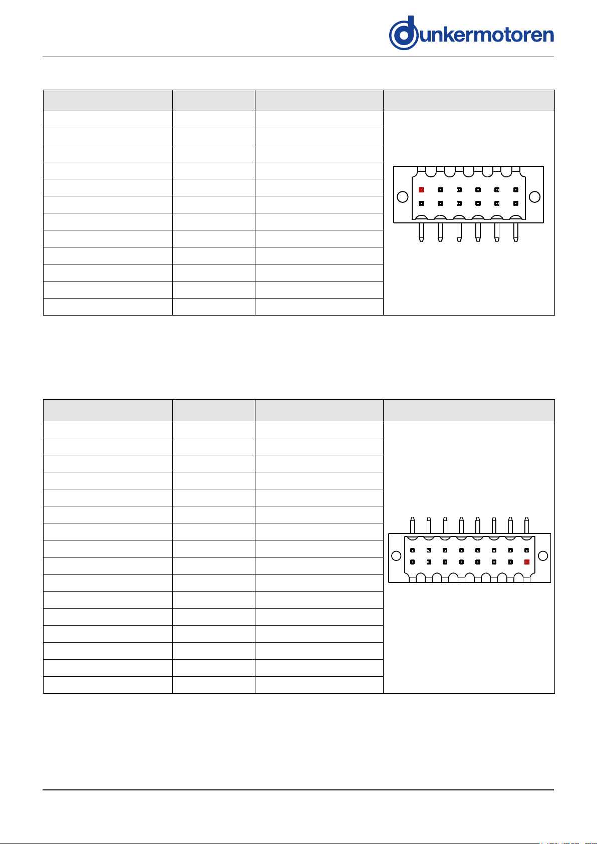
I/O-Connector I/O-Stecker
12 pin WE-Link connector:
F73-A-312-00250
PIN 1 PIN 3 PIN 9
PIN 2
PIN 4 PIN 6 PIN 8 PIN 10 PIN 12
PIN 11PIN 5 PIN 7
Function/ Funktion Pin Conductor color/ Leiterfarbe
Logic GND 1 -
Logic power 2 -
Out 0 3 -
Out 1 4 -
Out 2 5 -
GND (Connected to Pin 12) 6 -
In 0 7 -
In 1 8 -
In 2 9 -
In 3 10 -
In 4 11 -
GND (Connected to Pin 6) 12 -
AIN0- 13
AIN0+ 14
AIN1- 15
AIN1+ 16
-
-
-
-
16 pin WE-LINK connector:
F73-A-316-00250
PIN 16
PIN 15 PIN 3PIN 5PIN 7PIN 9PIN 11PIN 13
PIN 2PIN 4PIN 6PIN 8PIN 10PIN 12PIN 14
PIN 1
Version 12.2017 | Page/ Seite 11 www.dunkermotoren.com
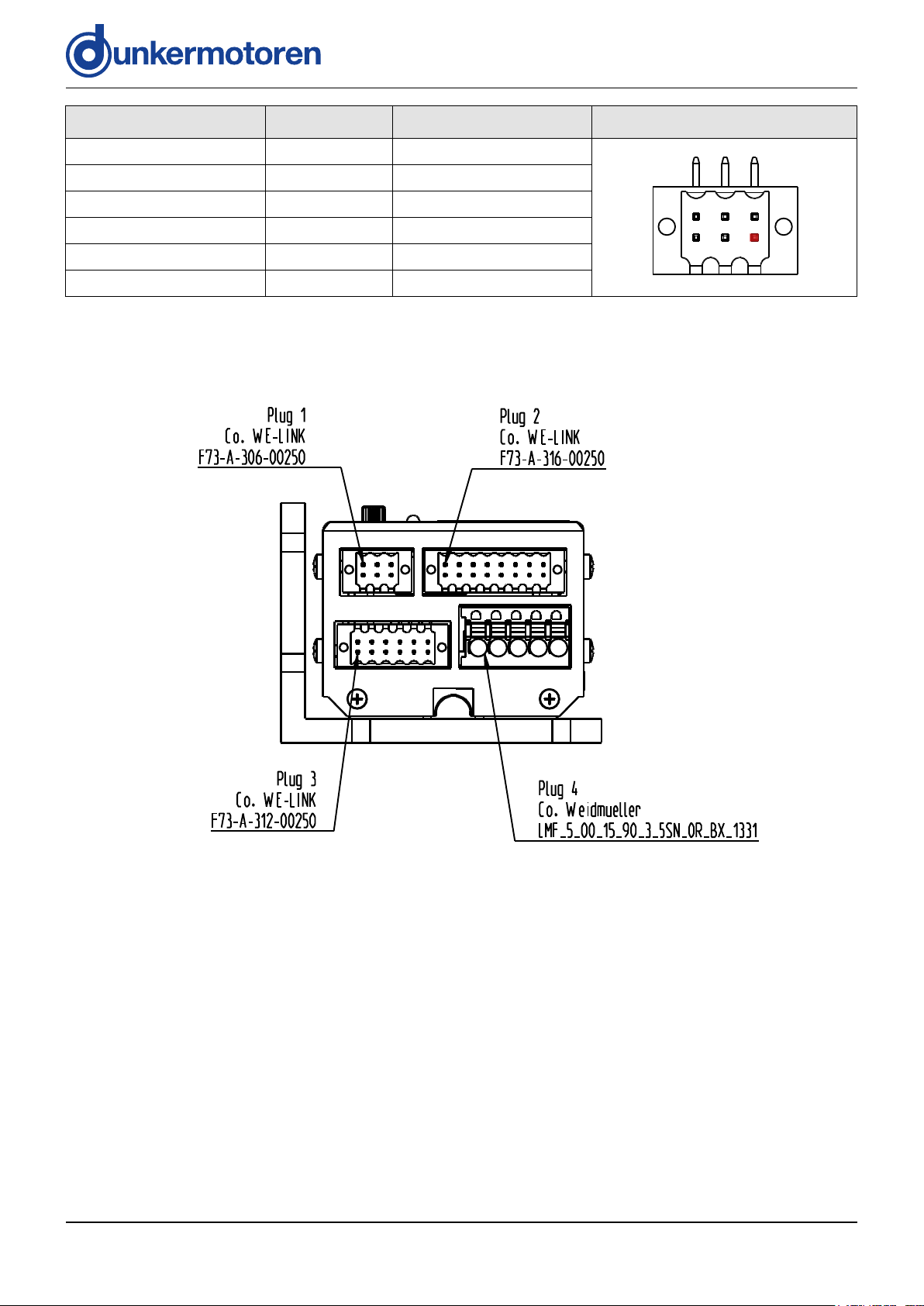
Function/ Funktion Pin Conductor color/ Leiterfarbe
RS485-A 1 -
RS485-B 2 -
6 pin WE-LINK connector:
F73-A-306-00250
GND 3 -
GND 4 -
RS485-A 5 -
RS485-B 6 -
PIN 2PIN 4PIN 6
PIN 1
PIN 3PIN 5
Version 12.2017 | Page/ Seite 12 www.dunkermotoren.com
5 Installation 5 Installation
Before commissioning, it is essential
that the safety instructions in the relevant section are read and understood,
5�1 Mechanical Installation 5�1 Mechanische Installation
NOTICE
Check the drive for visible damage before carrying out
the installation. Do NOT install damaged drives.
The drive must be fastened to a flat surface using 4
screw connections. The flange screws must be prevented from distortion by means of spring washers or glue.
and then observed! Non-observance
can result in danger to persons or
damage to the machine.
» Disconnect the electrical power
supply!
During installation, ensure that connectors are not damaged. Bent pins
can cause a short circuit and destroy
the drive!
WARNUNGWARNING
HINWEIS
Prüfen Sie den Antrieb vor der Installation auf äußerlich
sichtbare Beschädigungen. Bauen Sie beschädigte
Antriebe nicht ein.
Der Antrieb oder die externe BGE muss mit 4 Schraubverbindungen an einer planen Oberfläche befestigt
werden. Die Flanschschrauben müssen mit Federscheiben oder Schraubensicherungslack gegen Verdrehen
geschützt werden.
Vor der Inbetriebnahme sind unbedingt
die Sicherheitshinweise zu lesen und
zu beachten! Eine Nichtbeachtung kann zu Gefahren bei
Personen oder Beschädigungen an
der Maschine führen.
» Gerät spannungsfrei schalten!
Achten Sie bei der Installation darauf,
dass die Steckverbinder nicht beschädigt werden. Umgebogene Pins
können den Antrieb durch Kurzschluss
zerstören!
5�2 Electrical Installation 5�2 Elektrische Installation
5.2.1 Electro-magnetic compatibility 5.2.1 Elektromagnetische Verträglichkeit
During operation of the drive respectively the entire
system electromagnetic interference is created. Without suitable protective measures, this can influence
signals in control cables and parts of the installation and
endanger the operational reliability of the installation.
Before putting the machine into service, its electromagnetic compatibility must be checked and any necessary
measures taken.
5.2.2 Ground wire 5.2.2 Erdung
To comply with EMC-conformity, the
motor housing must be grounded.
NOTICE
Beim Betrieb des Motors, bzw. der gesamten Anlage
entstehen elektromagnetische Störstrahlungen. Diese
können ohne geeignete Schutzmaßnahmen die Signale
von Steuerleitungen und Anlageteilen beeinflussen und
die Betriebssicherheit der Anlage gefährden. Vor dem
Betrieb muss die elektromagnetische Verträglichkeit der
Anlage geprüft und sichergestellt werden.
Zur Einhaltung der EMV-Konformität
ist das Motorgehäuse zu erden.
HINWEIS
Version 12.2017 | Page/ Seite 13 www.dunkermotoren.com
NOTICE
Loops must be avoided for all grounding concepts. Shielded cable must be
used for the whole cable system without interruption. Up to a length of 10
m a common power and signal cable
can be used. If the cable is longer than
10 m it is recommended to separate
power and signal in dierent shielded
cables. When standard wires from
Dunkermotoren are used, the shielding
must be spaciously applied inside the
control cabinet.
HINWEIS
Grundsätzlich sind bei allen Erdungskonzepten Schleifen zu vermeiden.
Leistungsschirme sind über die
gesamte Verkabelung ohne Unterbrechung vorzusehen. Leistungs- und
Signalleitungen können bis zu einer
Länge von 10 m gemeinsam in einem
geschirmten Kabel geführt werden.
Übersteigt die Kabellänge 10 m, ist es
empfehlenswert, die Signal- und Leistungsleitungen in getrennt geschirmten Kabeln zu führen. Werden die
Dunkermotoren verfügbaren Standardkabel verwendet, so ist die Schirmung
im Schaltschrank breitächig aufzulegen.
» The connection of the motor housing to the machine
ground can be done with the motor flange.
» When the motor is electrically isolated mounted the
housing of the motor must be connected with the
machine ground via a separate wire.
» Die Verbindung des Motorgehäuses mit der
Maschinenerde kann über den Motorflansch erfolgen.
» Bei elektrisch isolierter Montage ist das Motor gehäuse über eine separate Erdleitung mit der
Maschinenerde zu verbinden.
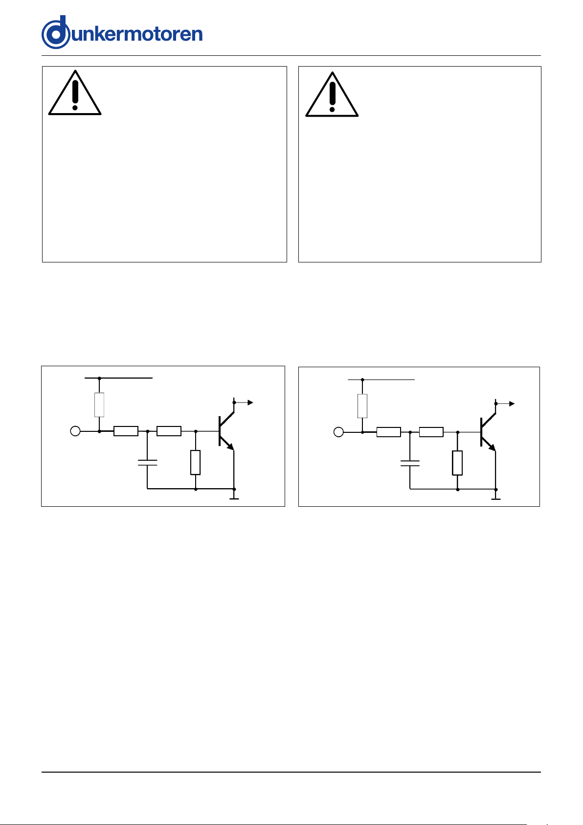
5.2.3 Schematic circuit of the digital inputs 5.2.3 Prinzipschaltung der Digitaleingänge
Logic supply
10k 1
Input
1
Optional for ground switching inputs
10k 10k
22nF
1,5k
1,2k
to µC
Eingang
1
Optional für massegeschaltete Eingänge
10k1)
Logikversorgung
10k 10k
22nF
1,2k
1,5k
5�3 Analog inputs 5�3 Analoge Eingänge
zum µC
5.3.1 Function analog input 5.3.1 Funktion analoger Eingang
» Funktionen siehe SI-Betriebsarten (Seite 28)» Functions, see SI operation modes (Page 28)
Version 12.2017 | Page/ Seite 14 www.dunkermotoren.com
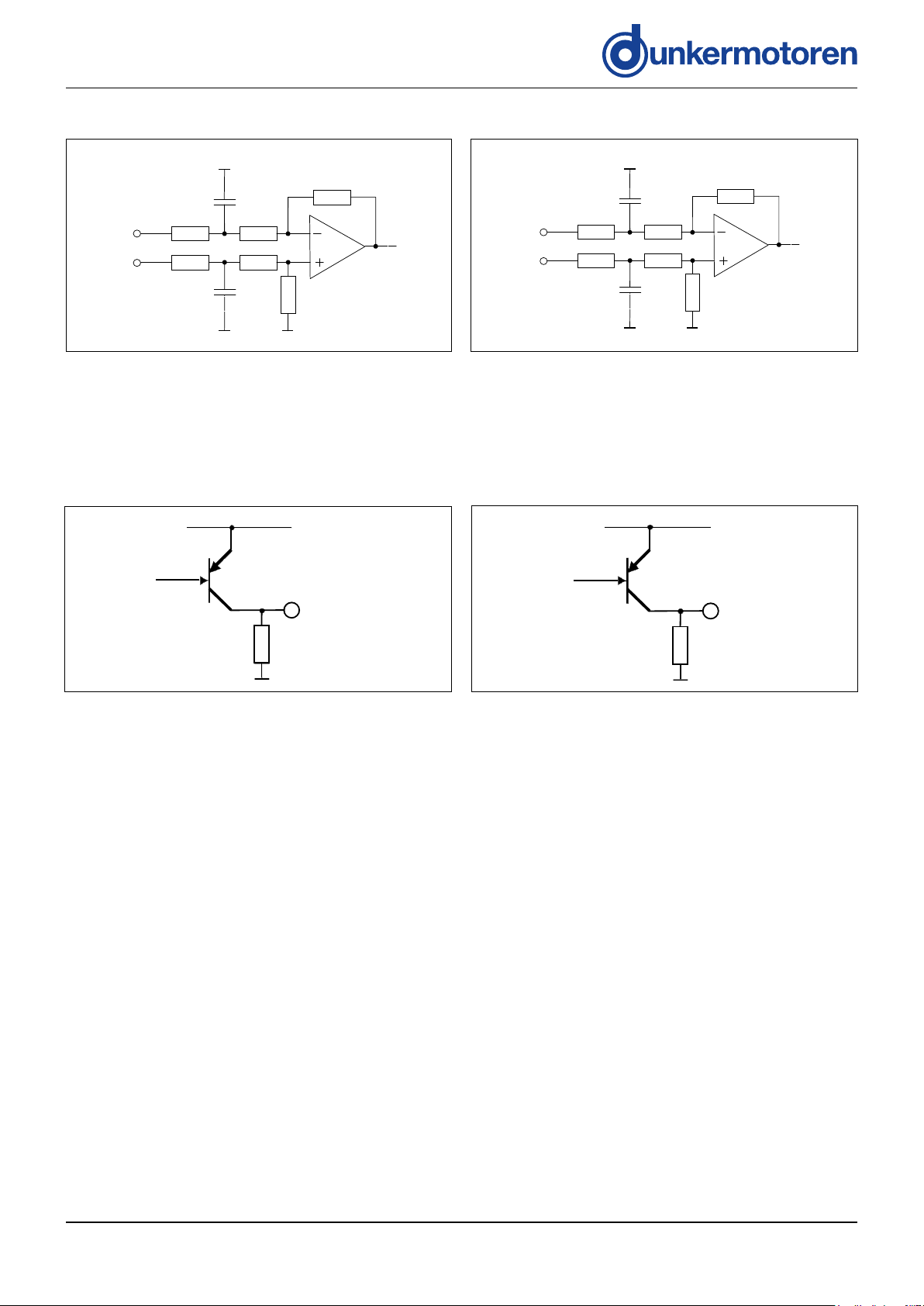
5.3.2 Schematic circuit of the analog input
10nF
AI-
AI+
48 kΩ
48 kΩ
47 kΩ
47 kΩ
10nF
to µC
12 kΩ
12 k
Ω
10nF
AI-
AI+
48 kΩ
48 kΩ
47 kΩ
47 kΩ
10nF
zum µC
12 kΩ
12 k
Ω
47
47
5.3.2 Prinzipschaltung Analogeingang
47
47
5�4 Digital outputs 5�4 Digitale Ausgänge
5.4.1 Function digital outputs 5.4.1 Funktion digitale Ausgänge
» Funktionen siehe SI-Betriebsarten (Seite 28)» Functions, see SI operation modes (Page 28)
5.4.2 Schematic circuit of the digital outputs 5.4.2 Prinzipschaltung der Digitalausgänge
from µC
Logic supply
Output chargeable
with max. 250 mA
Output
22k
47k
von µC
Logikversorgung
Ausgang maximal
mit 250 mA belastbar
Ausgang
22k
47k
Version 12.2017 | Page/ Seite 15 www.dunkermotoren.com
6 BGE 6e 6 BGE 6e
6�1 Power supply 6�1 Leistungsversorgung
» Klemme LMF 5.00 / 5 / 90 Fa. Weidmüller» Clamp LMF 5.00 / 5 / 90 Fa. Weidmüller
SNR. 27573.41709
L
6�2 I/O-Connector
6�2 I/O-Stecker
SNR. 27573.41718
Version 12.2017 | Page/ Seite 16 www.dunkermotoren.com
 Loading...