

dunkermotoren BG 44 SI Instruction Manual
Edition / Ausgabe (11/2013)
Instruction Manual / Betriebsanleitung
BLDC-motor with integrated speed controller
EC-Motor mit integriertem Drehzahlregler
BG 44 SI

2
Instruction Manual/Betriebsanleitung BG 44 SI, Version: 1.3 en_de
© 2013; Dunkermotoren GmbH; D-79848 Bonndorf; Germany
Page
1 Content 2
2 About this document 4
3 General description 5
3.1 Motor series BG 44 SI 5
3.2 Explanations of terms used 6
3.3 Proper use 6
3.4 Standards and guidelines 7
4 Safety instructions 8
5 Technical data, accessories 9
5.1 Electrical data 9
5.2 Mechanical data 9
5.3 Dimensions 10
5.4 Motor BG 44x25 SI 10
5.5 Motor BG 44x50 SI 10
5.6 Accessories 11
6 Protective functions 12
6.1 Recuperation during braking 12
6.2 Over-temperature protection 12
6.3 Current limitation 12
7 Installation / terminal assignment 13
7.1 Mechanical assembly 13
7.2 Electromechanical compatibility 13
7.3 Ground wire 14
7.4 Connection alternatives 15
7.5 Motor power supply and signal 15
interface supply 15
7.6 Schematic circuit of the digital outputs 16
7.7 Schematic circuit of the digital inputs 17
8 Connection schematic 18
8.1 Connection motor power supply and
signal interface supply 19
9 Operation hints 20
9.1 Operation 20
9.2 Function of the digital inputs IN1
and IN2 21
9.3 Function of the digital inputs IN3
and IN4 21
9.4 Teaching of xed speeds 22
9.5 Teaching of ramps 23
9.6 Function of the pulse output OUT1 25
9.7 Protection function and fault
Seite
1 Inhalt 2
2 Über dieses Dokument 4
3 Allgemeine Beschreibung 5
3.1 Motorbaureihe BG 44 SI 5
3.2 Begriffserklärungen 6
3.3 Bestimmungsgemäße Verwendung 6
3.4 Normen und Richtlinien 7
4 Sicherheitshinweise 8
5 Technische Daten, Zubehör 9
5.1 Elektrische Daten 9
5.2 Mechanische Daten 9
5.3 Motormasszeichnung 10
5.4 Motor BG 44x25 SI 10
5.5 Motor BG 44x50 SI 10
5.6 Optionale Anbauten 11
6 Schutzfunktionen 12
6.1 Rückspeisung bei Bremsvorgängen 12
6.2 Übertemperaturschutz 12
6.3 Strombegrenzung 12
7 Installation und Anschlussbelegung 13
7.1 Mechanische Montage 13
7.2 Elektromagnetische Verträglichkeit 13
7.3 Schutzleiter Anschluss 14
7.4 Anschlussmöglichkeiten 15
7.5 Spannungsversorgung Motor und 15
Schnittstellenversorgung 15
7.6 Prinzipschaltung der Digitalausgänge 16
7.7 Prinzipschaltung der Digitaleingänge 17
8 Anschlussschema 18
8.1 Anschluss Leistungsversorgung 19
Motor und Schnittstellenversorgung 19
9 Betriebshinweise 20
9.1 Inbetriebnahme 20
9.2 Funktion der Digitaleingänge IN1
und IN2 21
9.3 Funktion der Digitaleingänge IN3
und IN4 21
9.4 Teachen von festen Geschwindigkeiten 22
9.5 Teachen von Rampen 23
9.6 Funktion des Pulsausgangs OUT1 25
9.7 Schutzfunktionen und
1 Content
1 Inhalt

3
Instruction Manual/Betriebsanleitung BG 44 SI, Version: 1.3 en_de
© 2013; Dunkermotoren GmbH; D-79848 Bonndorf; Germany
output OUT3 26
9.8 Function of the analogue input
AI+/AI- 27
9.9 Motors with additional brake 28
10 Maintenance & Service 29
10.1 Motor operation in Q mode 29
10.2 Maintenance, taking out of service
and disposal 29
10.3 Service & Support 30
10.4 Scope of delivery and accessories 30
10.5 Download PDF-Data 30
Meldeausgang OUT3 26
9.8 Funktion des Analogeinganges
AI+/AI- 27
9.9 Motoren mit zusätzlicher Bremse 28
10 Wartung & Service 29
10.1 Motorbetrieb im Q-Modus 29
10.2 Wartung, Ausserbetriebsetzung
und Entsorgung 29
10.3 Service & Support 30
10.4 Lieferumfang und Zubehör 30
10.5 Download PDF-Daten 30
1 Content
1 Inhalt
4
Instruction Manual/Betriebsanleitung BG 44 SI, Version: 1.3 en_de
© 2013; Dunkermotoren GmbH; D-79848 Bonndorf; Germany
2 About this document
These operating instructions introduce you to the
SI drives and provide you with information on all the
stages required for the installation of the drives and the
performance of functional tests.
Notes:
Notes explain the advantages of certain settings and
help you to benet from the ideal prot of the appliance.
Warning notices!
read and follow them
carefully!
Warning notices should protect you from danger and
will help you to avoid of damages of the device.
Attention!
danger of life caused
by electric shock!
When you see this sign, you should always check for
the appliance for being voltage free and being protected against enabling by mistake.
2 Über dieses Dokument
Die vorliegende Betriebsanleitung stellt Ihnen die SIAntriebe vor und informiert Sie über alle Schritte zur
Installation der Antriebe und zur Durchführung von
Funktionstests.
Hinweise:
Hinweise erläutern Vorteile bestimmter Einstellungenund helfen Ihnen, den optimalen Nutzen aus dem Gerät zu ziehen.
Warnhinweise!
Lesen und befolgen
Sie diese sorgfältig!
Warnhinweise sollen Sie vor Gefahr schützen oder
helfen Ihnen, eine Beschädigung des Gerätes zu vermeiden.
Achtung!
Lebensgefahr durch
Stromschlag!
Wenn Sie dieses Zeichen sehen, dann prüfen Sie
stets ob das Gerät spannungsfrei und gegen ver-
sehentliches Einschaten gesichert ist.
2 About this document
2 Über dieses Dokument

5
Instruction Manual/Betriebsanleitung BG 44 SI, Version: 1.3 en_de
© 2013; Dunkermotoren GmbH; D-79848 Bonndorf; Germany
3 General description
3.1 Motor series BG 44 SI
The motor type BG 44 SI represents an EC-motors
(brushless DC motor) with an integrated speed control
electronics for 4-quadrant operation.
The desired speed is set via an analogue signal input
0 ... +10 V. The four operating modes “clockwise rotation”, “counter clockwise rotation”, “Off” (rapid breakpoint with freewheel) and “Stop” (rapid breakpoint with
holding torque) are controlled via the two digital inputs
IN1 and IN2. Optional, two further digital inputs for additional functions are available. Therewith, among other
things, 2 xed motor speeds (e.g. for rapid movement
and creep speed), acceleration ramp and braking ramp
can be memorized (Teach). Two digital output signals
are available additionally: one giving 6 pulses per turn
(e.g. for position and speed control), the other showing
“fault”. In case of larger needs, customer specic solutions with special rmware are available on request.
The motor has except of the ball bearings no expendable parts and is hence excellently suited for continuous
operation. The motors BG 44 SI can be combined with
planetary or worm gears with a multitude of ne tuned
gear ratios.
3 Allgemeine Beschreibung
3.1 Motorbaureihe BG 44 SI
Bei der Motorbaureihe BG 44 SI handelt es sich um
EC-Motoren (bürstenlose Gleichstrommotoren) mit integrierter Drehzahlregelelektronik für 4-Quadrantenbetrieb.
Die Drehzahlsollwertvorgabe erfolgt standardmäßig
über einen Analogspannungseingang 0 ... +10 V. Über
zwei digitale Eingänge (IN1, IN2) lassen sich die vier
Betriebszustände „Rechtslauf“, „Linkslauf“, „Aus“
(Schnellstopp mit Freilauf) und „Stopp“ (Schnellstopp
mit Haltemoment) ansteuern. Wahlweise stehen zwei
weitere digitale Eingänge für erweiterte Funktionalität
zur Verfügung. Damit lassen sich unter anderem 2 feste Motordrehzahlen (z.B. für Eil- und Schleichgang)
und Beschleunigungs- und Bremsrampen (z.B. für
sanftes Beschleunigen und Abbremsen) abspeichern
(teachen). Außerdem werden zwei digitale Ausgänge
herausgeführt, womit ein Pulsausgang mit 6 Impulsen
pro Umdrehung (z.B. für Positions- und Geschwindigkeitsüberwachung) und eine Fehlermeldung zur Ver-
fügung stehen. Kundenspezische Ausführungen mit
spezieller Firmware sind bei größeren Bedarfsfällen
auf Anfrage möglich.
Der Motor hat außer den Kugellagern keine Verschleißteile und eignet sich deshalb hervorragend auch für
Dauerbetrieb. Die Motoren BG 44 SI können auch mit
Planeten- oder Schneckengetrieben kombiniert werden, die in einer Vielzahl fein abgestimmter Untersetzungen verfügbar sind.
Motorstecker für Leistungsversorgung und Logik/
Plug for power and logic supply
EC-Motor/BLDC-motor
Integrierte Elektronik/
Electronic integrated
Integrierte Hallsensoren/
Hall sensors integrated
Kugelgelagerte Motorabtriebswelle, optional Getriebe/
Ball bearing motor output shaft, gearbox optionally
3 General description
3 Allgemeine Beschreibung
6
Instruction Manual/Betriebsanleitung BG 44 SI, Version: 1.3 en_de
© 2013; Dunkermotoren GmbH; D-79848 Bonndorf; Germany
3.2 Explanations of terms used
Bridge rectier
Component for the transformation from AC voltage to DC
voltage
Smoothing capacitor
Component to smooth the
uctuation voltage
Hall sensors
Sensors for determining the
position of a rotor
Index impuls
Reference mark of the integrated encoder panel
Ramps
Settings to accelerate and brake
the drive
CAN-Monitor
Adjustment- and storring possibility for speed and ramps
3.3 Proper use
- The BG 44 SI motor is a supplied part and may be
installed into (industrial) machinery and equipment in
the described conguration.
- The drive must be securely xed, and may only be
installed using cables and components specied by
Dunkermotoren.
- The drive may only be put into operation once the
entire system has been installed in accordance with
EMC.
3.2 Begriffserklärungen
Brückengleichrichter
Bauteil zur Umwandlung von
Wechselspannung in Gleichspannung
Glättungskondensator
Bauteil zur Glättung von
Spannungsschankungen
Hallsensoren
Sensor zur Positionsbestimmung des Rotors
Indeximpuls
Referenzmarke der integrierten Geberscheibe
Rampen
Einstellungen zum Beschleunigen und Bremsen des Antriebs
Techen / Toggeln
Einstellung und Abspeichermöglichkeit für Geschwindigkeiten
und Rampen
3.3 Bestimmungsgemäße Verwendung
- Der Motor BG 44 SI ist ein Zulieferteil und darf in der
beschriebenen Konguration in Maschinen und Anla-
gen eingesetzt werden (industrieller Bereich).
- Der Antrieb muss fest montiert werden und darf nur
mit den von Dunkermotoren spezizierten Kabeln
und Zubehörteilen eingesetzt werden.
- Der Antrieb darf erst nach EMV-gerechter Montage
des Gesamtsystems in Betrieb genommen werden.
3 General description
3 Allgemeine Beschreibung

7
Instruction Manual/Betriebsanleitung BG 44 SI, Version: 1.3 en_de
© 2013; Dunkermotoren GmbH; D-79848 Bonndorf; Germany
3.4 Standards and guidelines
EU guidelines: the EU guidelines formulate the mini-
mum requirements made on a product and must be observed by all manufacturers and dealers marketing the
product in the member states of the European Union.
Machine guideline: the drive is a machine in the
sense of the EU guideline for machinery. It has moveable parts in accordance with its intended purpose:
however, it may only be installed as a component of a
machine or a system. The advice described in these
instructions regarding installation and operation must
be adhered to.
EMC guideline: the EU guidelines for EMC apply to
devices which can cause electromagnetic interruptions
or whose operation can be impaired by these interruptions. Compliance of the drive with the EMC guideline
can only be tested once it has been installed. The information pertaining to EMC described in these instructions must be adhered to.
Conformity: by means of the conformity declaration of
the product (see appendix), Dunkermotoren conrms
that the drive complies with the safety standards listed
therein and with EMC standards. The product may be
sold and used within the European Union.
3.4 Normen und Richtlinien
EG-Richtlinien: Die EG-Richtlinien formulieren die
Mindestanforderungen an ein Produkt und müssen von
allen Herstellern und Händlern beachtet werden, die
das Produkt in den Mitgliedstaaten der Europäischen
Union auf den Markt bringen.
Maschinenrichtlinie: Der Antrieb ist eine Maschine im
Sinne der EG-Richtlinie für Maschinen. Er hat zweckgerichtet bewegliche Teile, darf aber nur als Bestandteil
einer Maschine oder Anlage eingesetzt werden. Die in
dieser Betriebsanleitung beschriebenen Hinweise zur
Installation und Inbetriebnahme müssen
beachtet werden.
EMV-Richtlinie: Die EG-Richtlinien für EMV gelten für
Geräte, die elektromagnetische Störungen verursachen können oder deren Betrieb durch diese Störungen
beeinträchtigt werden kann. Die Übereinstimmung des
Antriebs mit der EMV-Richtlinie kann erst nach dem
Einbau überprüft werden. Die in dieser Betriebsanleitung beschriebenen Angaben zur EMV müssen beachtet werden.
Konformität: Mit der Konformitätserklärung (siehe Anhang) des Produkts bescheinigt Dunkermotoren, dass
der Antrieb den dort aufgeführten Normen zur Sicherheit und EMV entspricht. Das Produkt darf in der Europäischen Union vertrieben und eingesetzt werden.
3 General description
3 Allgemeine Beschreibung
8
Instruction Manual/Betriebsanleitung BG 44 SI, Version: 1.3 en_de
© 2013; Dunkermotoren GmbH; D-79848 Bonndorf; Germany
4 Safety instructions
Attention!
Before starting, the following safety instructions
must be read and observed necessarily. Nonobservance may cause
hazards of persons or
damage machines!
Failure-free operation requires transport and storage
according to the appropriate requirements. The drives
are to be stored protected against dust, dirt and humidity. It is essential, that the storage conditions are
not beyond the allowed storage temperature resp. air
humidity (see “Technical data”).
The transport must be knock-protected in compliance
with the storage conditions.
The instruction for installing and adjustment of the
drives must be considered.
To enable failure-free operation, a mounting place
should be selected, which environmental conditions
are not beyond the allowed values. The exact values
can be taken from the product description (see “Technical data”).
Mounting or demounting may only take place
under voltage-free condition.
The modules may only be implemented and equipped
by qualied staff according to appropriate standards.
A person can be classied as qualied,
• if he is able to identify and avoid possible dangers as
a result of experience,
• if he knows the accident prevention regulations for
the used devices
and
• if he is permitted to start up and install the electric
circuit and devices according to the standards.
The equipment may only be started up by qualied or
adequate indoctrinated persons.
The local standards at the application area of the devices must be considered.
The safety instructions of the operating devices and
machines must be considered.
To avoid danger, a fully functional EMERGENCYSTOP-button must be placed in direct scope with unhindered access.
4 Sicherheitshinweise
Achtung!
Vor der Inbetriebnahme sind unbedingt die
nachfolgen Sicherheitshinweise zu lesen und
zu beachten! Eine Nichtbeachtung kann zu Gefahren bei Personen
oder Beschädigungen
an der Maschine führen!
Der störungsfreie Betrieb setzt den Transport und die
Lagerung nach den entsprechenden Vorgaben voraus.
Die Antriebe sind geschützt vor Staub, Schmutz und
Feuchtigkeit zu lagern. Es ist zu beachten, dass die Lagerungsbedingungen nicht außerhalb der zulässigen
Lagerungstemperatur bzw. Luftfeuchtigkeit liegt (siehe
„Technische Daten“).
Der Transport muss stossgeschützt unter Einhaltung
der Lagerungsbedingungen erfolgen.
Die Anleitung für den Aufbau und die Einrichtung
der Antriebe ist zu beachten.
Um einen störungsfreien Betrieb zu ermöglichen, ist
ein Montage-Ort zu wählen, der keine Umweltbedingungen aufweist, die außerhalb der zulässigen Werte
liegen. Die genauen Werte sind der Produktbeschreibung zu entnehmen (siehe „Technische Daten“).
Die Montage oder Demontage darf nur im spannungslosen Zustand erfolgen.
Die Module dürfen nur von qualiziertem Personal
nach den entsprechenden Normen eingebaut und ein-
gerichtet werden. Als qualiziert gilt eine Person dann,
• wenn sie aufgrund ihrer Erfahrung mögliche Gefah-
ren erkennen und vermeiden kann,
• wenn ihr die Unfallverhütungsvorschriften für die
eingesetzten Geräte bekannt sind
und
• wenn sie gemäß den Normen Stromkreise und Ge-
räte in Betrieb setzen und installieren darf.
Die Anlage darf nur durch qualiziertes oder entsprechend geschultes Personal in Betrieb genommen werden.
Die regionalen Normen im Einsatzgebiet der Antriebe
sind zu beachten.
Die Sicherheitshinweise der zu steuernden Geräte und
Maschinen sind zu beachten.
Um Gefahren abwenden zu können, muss ein funktionstüchtiger NOT-AUS-Schalter in direkter Reichweite mit
unbehindertem Zugang liegen.
4 Safety instructions
4 Sicherheitshinweise
9
Instruction Manual/Betriebsanleitung BG 44 SI, Version: 1.3 en_de
© 2013; Dunkermotoren GmbH; D-79848 Bonndorf; Germany
5 Technical data, accessories
5.1 Electrical data
Maximum motor speed
range
0 ... 5000 U/min
*
Speed range adjustable 150 ... 4096 U/min
*
Minimum motor
voltage
20 V DC
Maximum motor
voltage
30 V DC
Maximum ripple on
supply voltage
Max. 5 %
Undervoltage shutdown < 19 V
Demolition boundary by
overvoltage
> 35 V
Required external fuse 8 AT external
Over-temperature
protection
> 100°C at the
power output stage
Max. peak current
(motor)
9 A
*
Maximum speed is limited by load
5.2 Mechanical data
Temperature range
motor
-20 °C ... +100 °C
housing temperature
Recommended environmental temperature range *)
0 °C ... 50 °C
Relative humidity
(not condensing)
Max. 90%
Protection class **)
IP50 (in special versions
up to IP65)
Connector plug
12-pole ***)
Round connector accor-
ding DIN 45326, compa-
ny Binder, series 723
*) The motor is specied for an ambient temperature
of 20°C. The performance data refer to this ambient
temperature.
**) The protective system only refers to the motor /
gearbox casing. The shaft is to be sealed by the client.
The drive may only be used in an environment complying with IP54 if the shaft outlet has been installed
such that it is protected from dust and water.
***) Please see the pin diagram for further information.
5 Technische Daten, Zubehör
5.1 Elektrische Daten
Ungeregelter
Drehzahlbereich
0 ... 5000 U/min
*
Regelbarer Drehzahlbereich 150 ... 4096 U/min
*
Minimal zulässige Motorspannung
20 V DC
Maximal zulässige Motorspannung
30 V DC
Zulässige Restwelligkeit
der Versorgungsspannung
Max. 5 %
Unterspannungsabschaltung < 19 V
Zerstörungsgrenze durch
Überspannung
> 35 V
Absicherung 8 AT extern erforderlich
Übertemperaturabschaltung
> 100°C an der
Leistungsendstufe
Max. Spitzenstrom
(Wicklung)
9 A
*
Maximaldrehzahl wird durch Last begrenzt
5.2 Mechanische Daten
Temperaturbereich
Motor
-20°C…+100°C
Gehäusetemperatur
Empfohlener Umgebungstemperaturbereich *)
0°C…50°C
Relative
Luftfeuchtigkeit
Max. 90%
Schutzart **)
IP 50 (in Sonderaus-
führungen bis IP 65)
Anschlussstecker
12-polig ***)
Rundstecker nach
DIN 45326, Firma
Binder, Serie 723
*) Der Motor ist für eine Umgebungstemperatur von
20°C speziziert. Die Leistungsangaben beziehen sich
auf diese Umgebungstemperatur.
**) Die angegebene Schutzart bezieht sich nur auf das
Motor- bzw. Getriebegehäuse. Die Abdichtung der Welle
ist vom Kunden vorzunehmen. Nur wenn der Wellenaustritt staub- und wassergeschützt montiert wird, kann der
Antrieb in einer Umgebung entsprechend IP54 eingesetzt werden.
***) Weitere Informationen nden Sie im Abschnitt An-
schlussbelegung.
5 Technical data, accessories
5 Technische Daten, Zubehör
10
Instruction Manual/Betriebsanleitung BG 44 SI, Version: 1.3 en_de
© 2013; Dunkermotoren GmbH; D-79848 Bonndorf; Germany
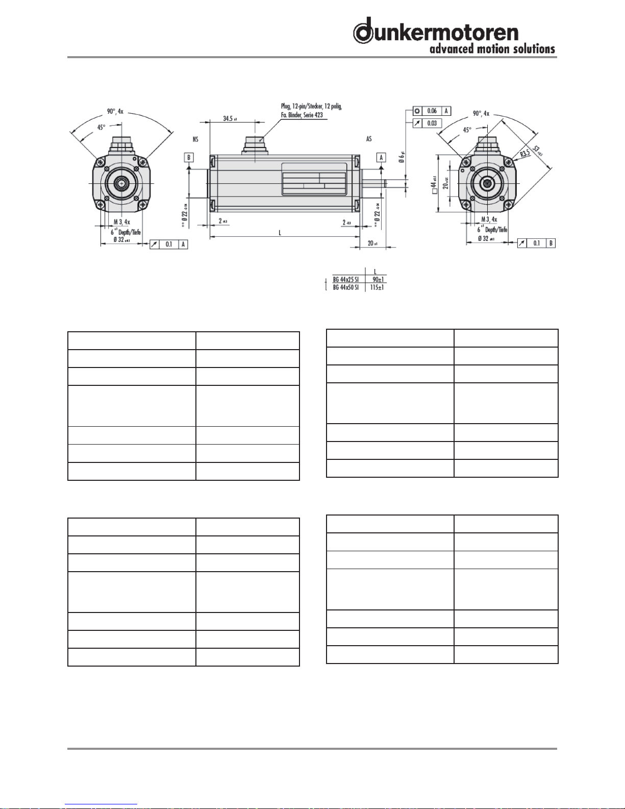
5.3 Dimensions
5.4 Motor BG 44x25 SI
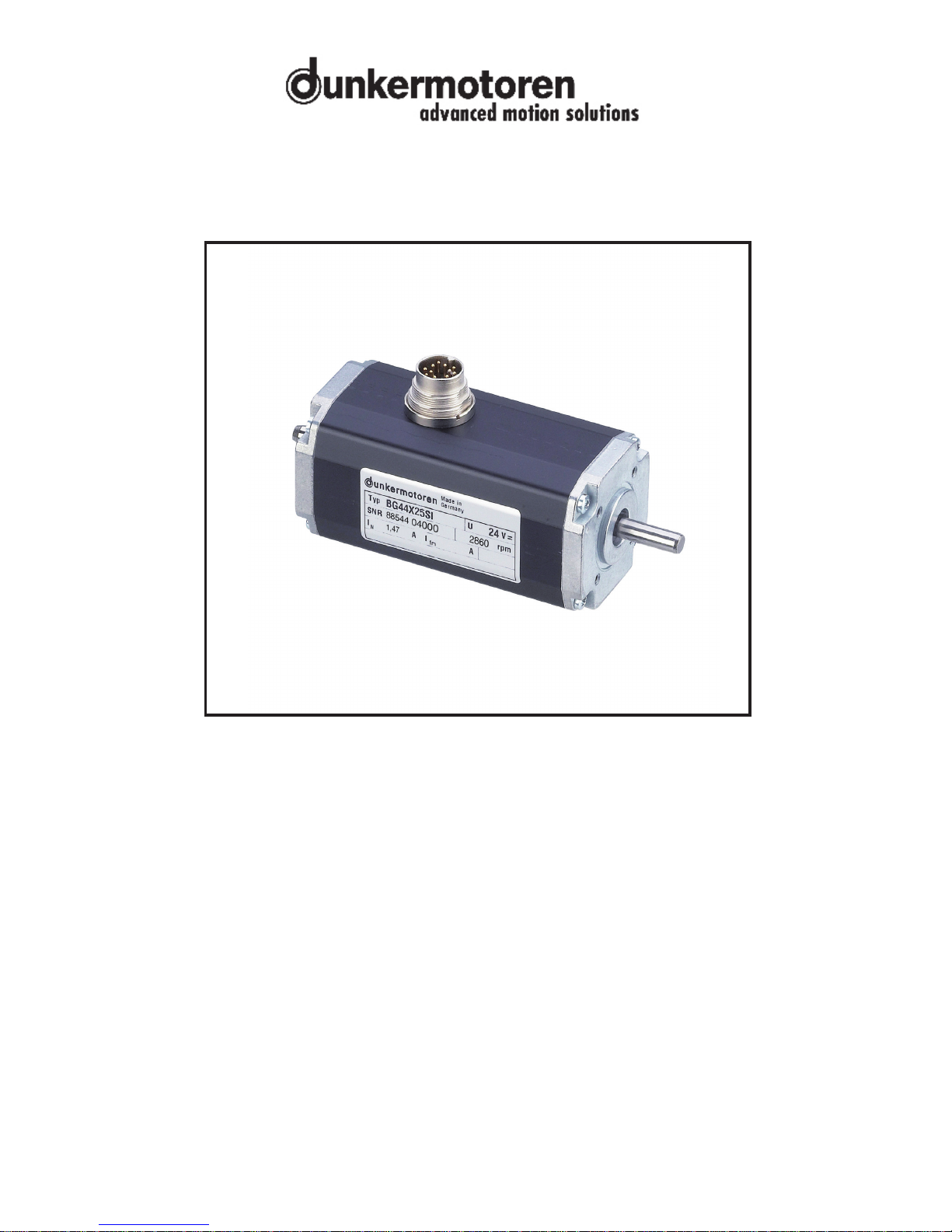
Nominal power 17,3 W
Nominal torque *) 5,7 Ncm
Rated speed 2860
Nominal supply voltage
24 V (standard),
special voltage on
request
Nominal current 1,47 A
Length 90 mm
Weight ca. 470 g
5.5 Motor BG 44x50 SI
Nominal power 36,7 W
Nominal torque *) 10,2 (12) Ncm
Rated speed 3440
Nominal supply voltage
24 V (standard),
special voltage on
request
Nominal current 2,52 A
Length 115 mm
Weight ca. 660 g
*) The nominal torque depends on the motor‘s heat
dissipation. The tables thus list the values taken in accordance with VDE (the German Electrical Engineers’
Association) / EN (European Standard) and taken during the installation of a thermally-conductive steel plate
with the dimensions 105x105x10mm (data in brackets).
5.3 Motormasszeichnung
5.4 Motor BG 44x25 SI
Nennleistung 17,3 W
Nenndrehmoment *) 5,7 Ncm
Nenndrehzahl 2860
Nennspannung
24 V (Standard), Son-
derspannung
auf Anfrage
Nennstrom 1,47 A
Länge 90 mm
Gewicht ca. 470 g
5.5 Motor BG 44x50 SI
Nennleistung 36,7 W
Nenndrehmoment *) 10,2 (12) Ncm
Nenndrehzahl 3440
Nennspannung
24 V (Standard), Son-
derspannung
auf Anfrage
Nennstrom 2,52 A
Länge 115 mm
Gewicht ca. 660 g
*) Das Nenndrehmoment ist abhängig von der Wärmeabführung des Motors. In den Tabellen aufgeführt
sind deshalb die Werte gemessen nach VDE/EN sowie gemessen bei Montage einer thermisch leitenden
Stahlplatte der Größe 105 x 105 x 10 mm (Angabe in
Klammern).
5 Technical data, accessories
5 Technische Daten, Zubehör
 Loading...