

Page 1

INSTALLATION,
INSTALLATION,
Form No.: MM0305F/MM0307A
R
OPERATION &
OPERATION &
MAINTENANCE
MAINTENANCE
MANUAL
MANUAL
Products That Perform...By People Who Care
ACCS
HEB-D
Air - Cooled
Split System
Air Conditioner
with Scroll
Compressors
R22 / R407C
VEB-D
COOLING
HEAT PUMP
Page 2

TABLE OF CONTENTS
DESCRIPTION PAGE NO
1.0 INTRODUCTION.............................................................................................................................................3
1.1 NOMENCLATURE.................................................................................................................................. 3
2.0 GENERAL INFORMATION
2.1 RECEIVING, INSPECTION AND PACKAGING .....................................................................................4
2.1.1 Air-Cooled Condensing Units ( ACCS ) ....................................................................................... 4
2.1.2 Evaporator Blower Units ( HEB/VEB/EB )....................................................................................4
2.2 RIGGING AND UNCRATING .................................................................................................................4
2.3 LIMITATIONS.........................................................................................................................................4
3.0 INSTALLATION
3.1 CONDENSING UNITS INSTALLATION.................................................................................................5
3.2 AIR COOLED CONDENSING UNITS CLEARANCE..............................................................................6
3.3 EVAPORATOR BLOWER UNITS INSTALLATION................................................................................ 8
3.3.1 Typical VEB / EB Ducting System.............................................................................................. 8
3.3.2 Typical HEB Ducting System..................................................................................................... 8
3.4 EVAPORATOR BLOWER UNITS CLEARANCE....................................................................................9
3.4.1 Vertical Casing Type – VEB, EB................................................................................................9
3.4.2 Horizontal Casing Type – HEB ................................................................................................ 10
3.5 DUCT CONNECTION........................................................................................................................... 11
3.6 FIELD PIPING ...................................................................................................................................... 11
3.7 REFRIGERANT PIPING....................................................................................................................... 13
3.8 LEAK TEST ( SYSTEM PRESSURE TEST )........................................................................................ 14
3.9 VACUUM TEST AND DEHYDRATION................................................................................................. 14
3.10 INSTALLATION OF DRIERS OR SIGHT GLASS................................................................................. 15
3.11 CHARGING .......................................................................................................................................... 15
3.12 LUBRICATION...................................................................................................................................... 15
3.13 SENSING BULB LOCATION................................................................................................................ 15
3.14 EXTERNAL EQUALIZER CONNECTION............................................................................................. 16
3.15 HOT GAS BYPASS .............................................................................................................................. 16
3.16 TIGHTENING OF PULLEY SET SCREW............................................................................................. 17
3.17 PULLEY ALIGNMENT.......................................................................................................................... 17
3.18 BELT TENSION INSPECTION GUIDE................................................................................................. 17
4.0 OPERATION
4.1 PHASE ROTATION.............................................................................................................................. 18
4.2 CYCLE LIMIT RATE............................................................................................................................. 18
4.3 FAN CYCLING (OPTIONAL, STANDARD FOR HEAT PUMP)............................................................ 18
4.4 DEFROST CYCLE (STANDARD FOR HEAT PUMP) .......................................................................... 18
4.5 CRANKCASE HEATER (HEAT PUMP)................................................................................................ 18
4.6 STOP VALVE ....................................................................................................................................... 18
4.7 HYDROPHILIC CONDENSER COIL (STANDARD FOR HEAT PUMP)............................................... 18
4.8 STAINLESS STEEL BOLTS AND NUTS .............................................................................................. 18
4.9 DIMENSIONAL DATA........................................................................................................................... 19
4.10 TYPICAL OPERATING SEQUENCE.................................................................................................... 24
5.0 MAINTENANCE
5.1 MAINTENANCE.................................................................................................................................... 25
5.2 TROUBLE SHOOTING CHART ........................................................................................................... 26
5.3 SAMPLE LOG SHEET.......................................................................................................................... 29
2
Page 3
1.0 INTRODUCTION
The Dunham-Bush air-cooled split system air conditioner and heat-pumps
are designed, matched, manufactured tested and ready for installation when
it reached the site. The evaporator unit consists mainly of a direct expansion
evaporator coil(s) with factory package thermal expansion valve, to be
coupled with air cooled condenser unit consisting of scroll compressor(s)
and large heat rejection condenser coil with integral subcooling circuit(s).
Factory standard units also incorporate important safety and operating
controls which includes manual reset high and low pressure cutout and
compressor motor protectors for each compressor(s).
Every Dunham-Bush air-cooled split air-conditioner and heat pumps have
been subject to stringent quality control and accurately testing as a final
verification of reliability. If it is correctly installed, operated and
maintained, it will provide many years of satisfactory and efficient
performance.
Note: These instructions are general in nature and are for standard
units only. Non-standard units may vary in some respects from
these instructions to suit particular applications.
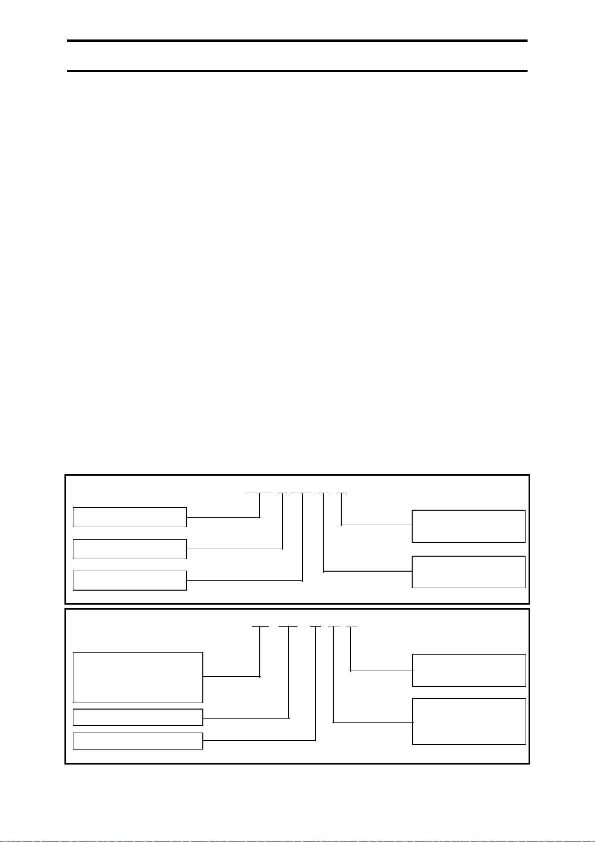
1.1 NOMENCLATURE
ACC S 445 Q P
Air Cooled Condensing
S - Scroll Compressor
Model Code
EB 445 D Q P
VEB/ EB - Vertical
HEB - Horizontal Evaporator
Model Code
Evaporator Blower
Blower
Generation
Blank - R22
P - R407c
Blank - Standard
Q - Special
Blank - R22
P - R407c
Blank - Standard
FB - Free Blow
Q - Special
3
Page 4

2.0 GENERAL INFORMATION
2.1 RECEIVING,
INSPECTION AND
PACKAGING
As soon as the unit is received, it should be
inspected if there is any damage during transit.
Make a separate written request if there is any
damage on the carrier's delivery order. Also,
the unit should be inspected for any missing or
short shipped components. Standard items and
accessories that come with the unit are:
2.1.1 AIR-COOLED CONDENSING
UNITS (ACCS)
1.) Compressor(s) c/w rubber grommet.
2.) Condenser coil(s).
3.) Condenser fan(s)- Refer to physical
data for sizes and quantity.
4.) Condensers fan motor(s)- Refer to
physical data for horsepower and
quantity.
5.) Fan grille.
6.) High and Low pressure switch.
7.) Reversing valve, check valve
suction accumulator and
compressor crankcase heater
(standard for heat pump only).
8.) Optional accessories (if any).
1. IEC-DOL (Direct On Line)
starter, wired
2. Low ambient fan cycling
(standard for Heat-Pump).
3. Hot gas bypass
4. Stop valves
5. Mains isolator
6. Hydrophilic condenser coil fins
(standard for Heat Pump)
7. Indicator lights
8. Stainless steel bolts and nuts
2.1.2 EVAPORATOR BLOWER
UNITS (HEB-D/ VEB-D/ EB-D)
1.) Blower(s) wheel.
2.) Evaporator coil.
3.) Thermal expansion valve(s) and
distributor(s).
4.) Bearings and shaft.
5.) Optional accessories.
1. Double wall casing
2. Hot water heating coil
3. Electric heater coil
4. Thermostat, unit mounted for
cooling only
5. Thermostat, remotely mounted
for cooling only and heat pump
6. Discharge plenum and return
air grille
2.2 RIGGING AND
UNCRATING
Each unit has been tested, inspected and
properly packed or crated prior to delivery. It
is very important that precaution is taken in
handing the units by the installers, movers and
riggers. When lifting with slings, use spreader
bars across the top of the unit to prevent any
damage to the frame and panels. Rigging
should be done in a manner to avoid any
severe strain or stress on the unit which will
scratch the paint works and damage the panels
and framework. Avoid possible surface
damage by not removing the packaging
material until the unit is at or near the final
location and soon to be installed. Check the
weight of the unit before rigging. Place the
rigging cable such that the weight is evenly
distributed.
2.3 LIMITATIONS
1.) Avoid low return air temperature on
evaporator coil which might cause
condensate to freeze up the surface of the
evaporator coil.
2.) Avoid moisture carry over and excessive
noise, limit evaporator coil face velocity
to 3.05 m/s [600FPM].
3.) Unit must be operated on the correct
electrical supply as specified on unit
nameplate. Voltage limitation for
compressor(s) and fan motor must be
observed.
4.) Avoid low return air temperature on the
condensing coil which might cause low
discharge pressure (heat pump unit is
equipped with fan cycling to maintain the
head pressure). Refer to Table 2.3.
TABLE 2.3 LIMITATION
(AIR TEMPERATURE °F[°C])
DB WB
INDOOR MAX. 95 [35] 72 [22]
MIN. 66 [19] 57 [14]
OUTDOOR MAX. 115 [46] -
MIN. 66 [19] -
4
Page 5
3.0 INSTALLATION
3.1 CONDENSING UNITS
INSTALLATION
In installing the condensing units,
considerations should be given to the
following:
1.) Installed outside the building or ensure
sufficient air to the condenser.
2.) Strong foundation to withstand the unit's
weight and vibration. If the base was not
leveled, use concrete blocks as base. It is
also suggestable to provide rubber or
spring isolators to isolate the units
vibration.
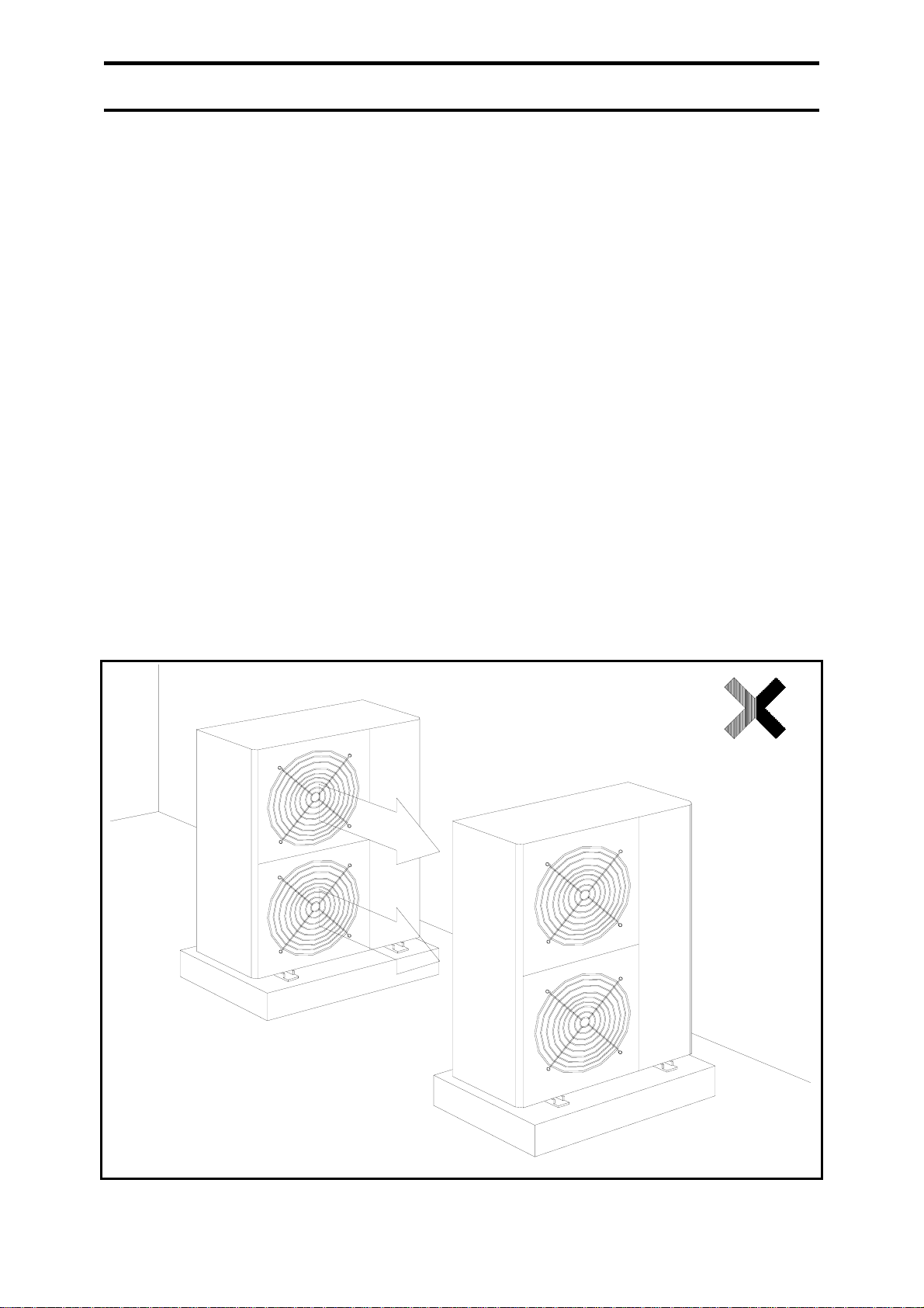
If installing two units together, make sure
that the discharge air from one unit were
not circuited by the other unit. (Figure
3.1.)
5.) Location where there is no direct heat
source such as near a generator. This is
because if the entering air temperature is
high, then the unit will operate at high
condensing temperature and subsequently
trip on high pressure (during cooling
mode).
6.) Location where the unit is not exposed to
oily area, salty atmosphere, and sulphide
gaseous area.
3.) Sufficient space for wiring and
maintenance as per local legislation.
4.) Location where air is allowed to circulate.
Note: Condenser fans are of the propeller
type and not suitable for use with
ductwork.
FIGURE 3.1: INSTALLING TWO UNITS TOGETHER
5
Page 6
3.0 INSTALLATION
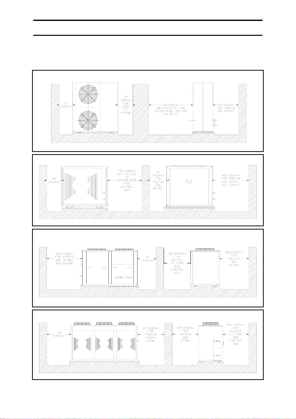
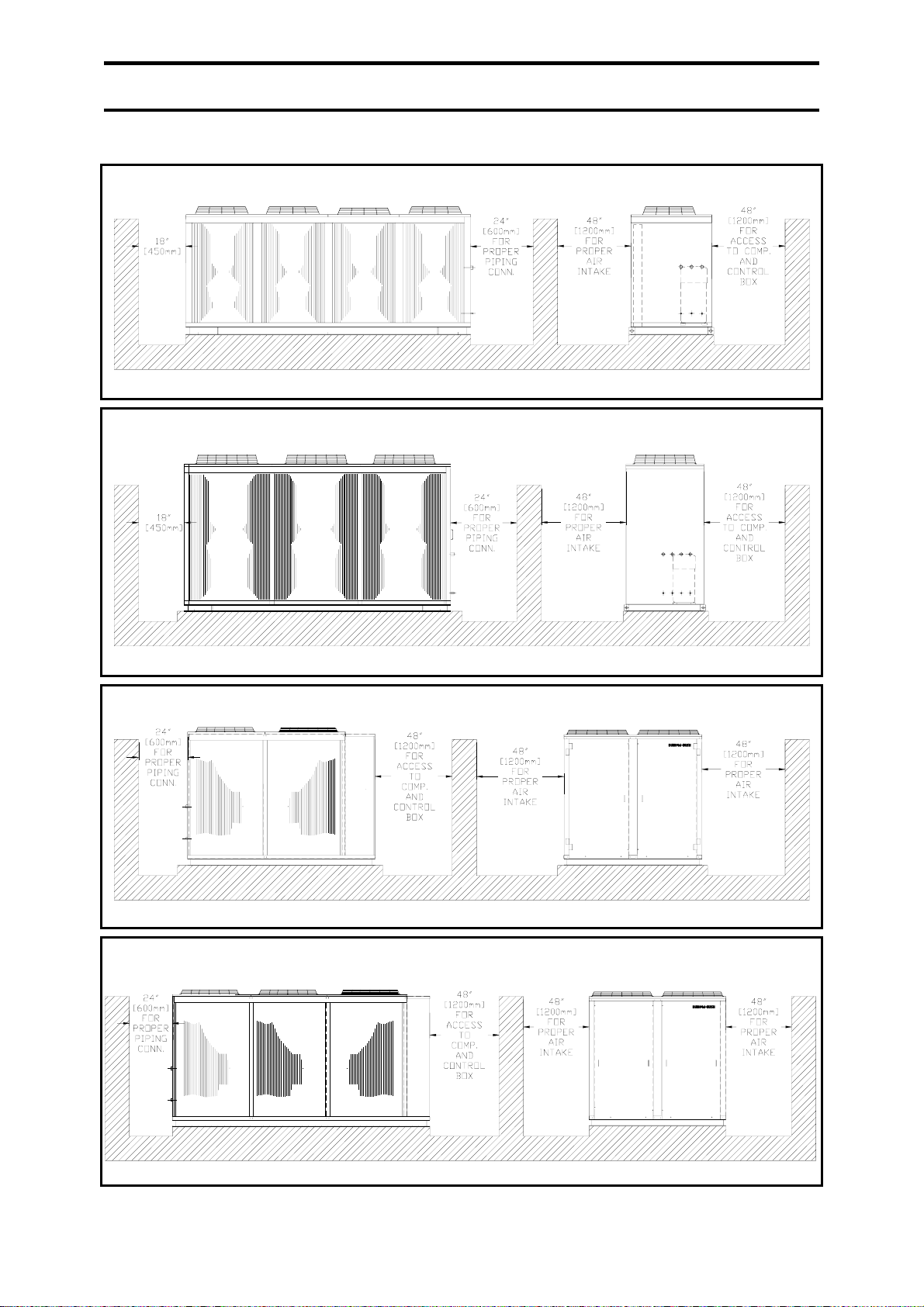
3.2 AIR-COOLED CONDENSING UNITS CLEARANCE
(SUGGESTED)
ACCS 68, 81, 95
ACCS 108, 125, 145
ACCS 160, 190, 220, 250, 290
ACCS 320, 380, 435
6
Page 7
3.0 INSTALLATION
ACCS 480, 510, 570
ACCS 640, 700, 760
ACCS 800, 890, 960
ACCS 1020, 1140, 1340, 1520
7
Page 8
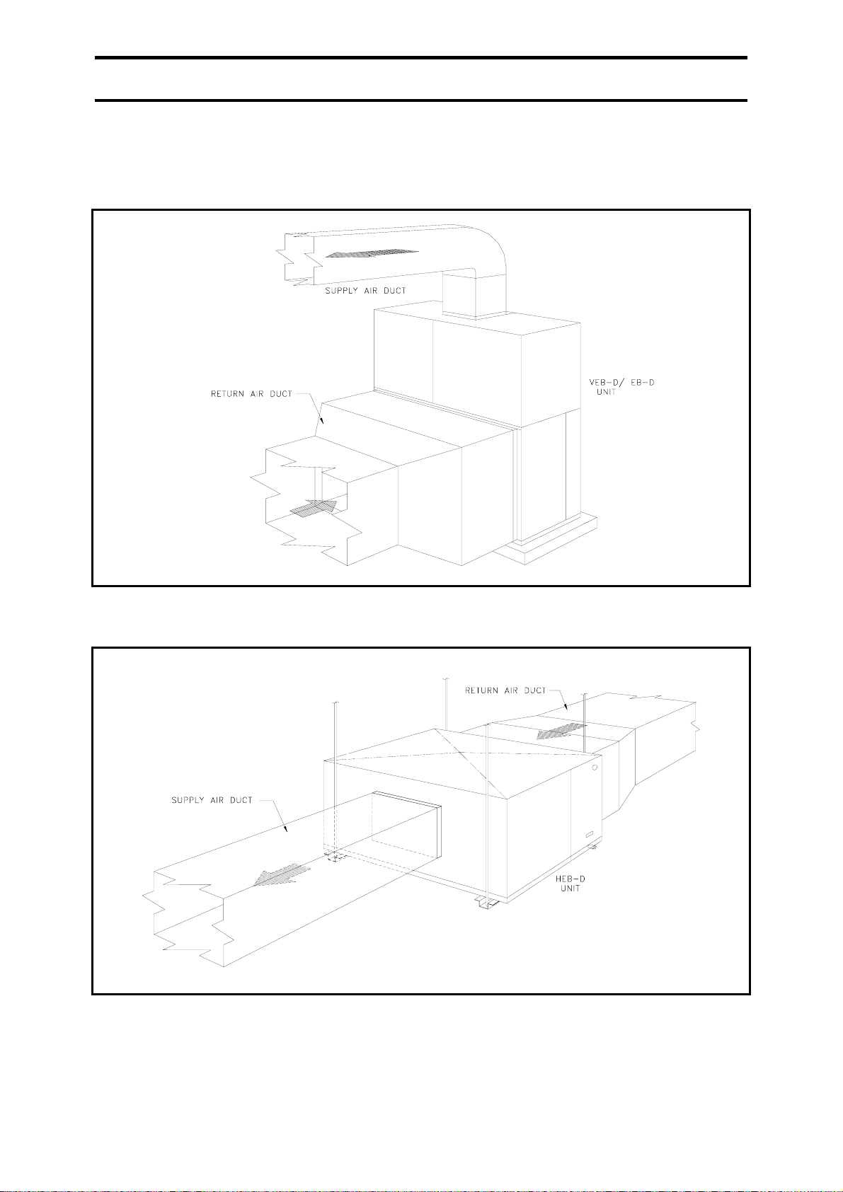
3.0 INSTALLATION
3.3 EVAPORATOR BLOWER UNITS INSTALLATION
3.3.1 TYPICAL VEB-D / EB-D DUCTING SYSTEM
3.3.2 TYPICAL HEB-D DUCTING SYSTEM
Leave the unit in its packaging until it reaches the final destination. This unit is designed for indoor
installation only. In installing the unit, these suggestions should be given consideration so that the
unit will operate with optimum capacity and also to ease the installation and future services.
8
Page 9
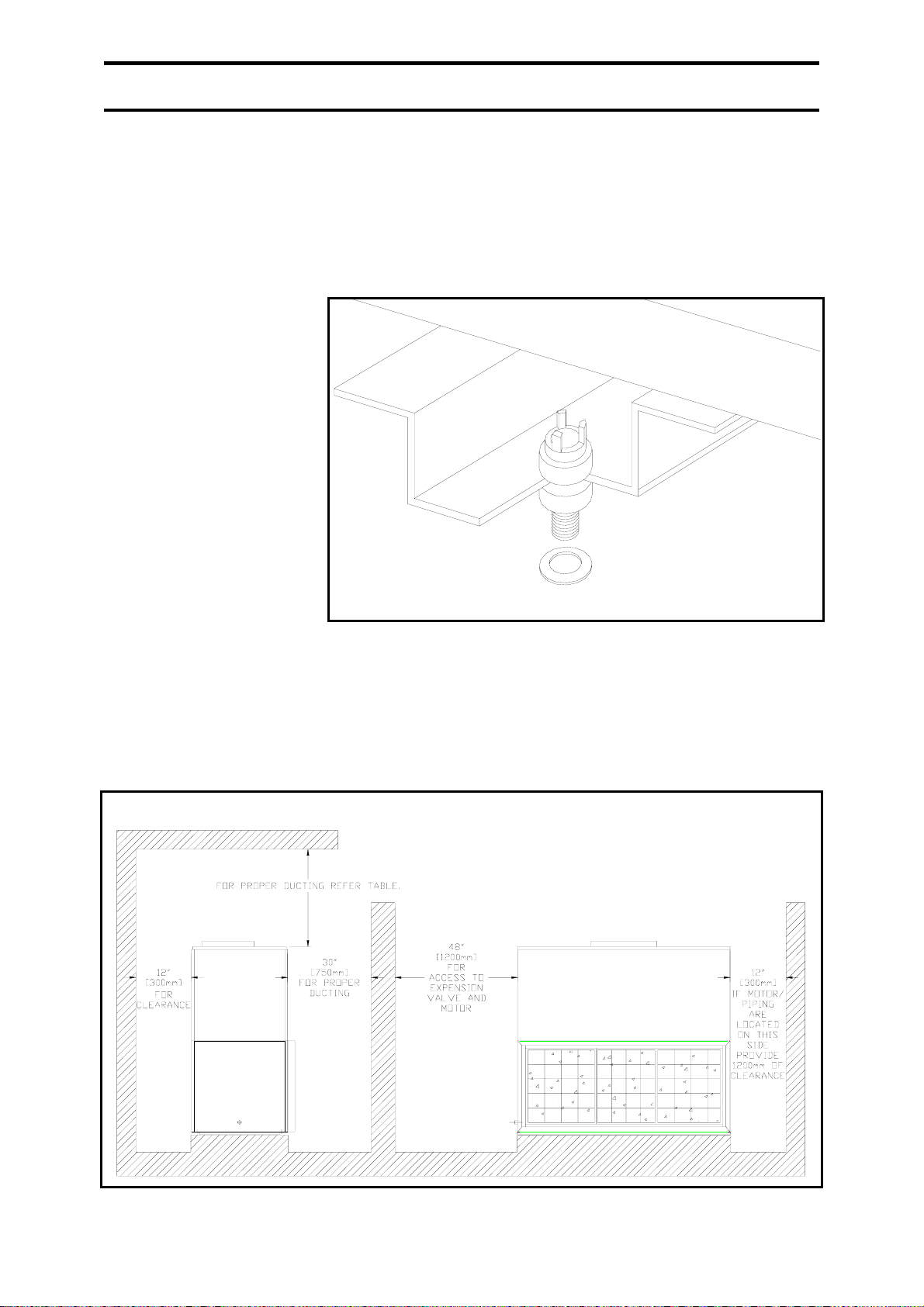
3.0 INSTALLATION
1.) Location that can withstand the unit's weight.
a.) Sometimes it is necessary to reinforce the ceiling with crossbeam or framework.
b.) Use suspension bolts to install the unit and make sure the bolts can withstand the weight
distribution.
2.) Location that minimize the drain piping and field piping distance.
3.) Location that minimize the ducting length.
4.) Location where there is
no direct heat and air is
allowed to circulate.
5.) It is suggestable to place
the unit higher than the
floor level, for ease of
drain piping. The base
should be 4” [100mm]
higher and leveled. Fix
the unit to the base with
anchor bolts. It is also
suggestable to place
vibrating isolation
component between the
unit and the base.
6.) Check the levelness of
the ceiling using a level
gauge.
3.4 EVAPORATOR BLOWER UNITS CLEARANCE
3.4.1. VERTICAL CASING TYPE- VEB, EB
a.) VEB 108D, 125D, 145D, 160D, 190D, 220D, 250D
9
Page 10
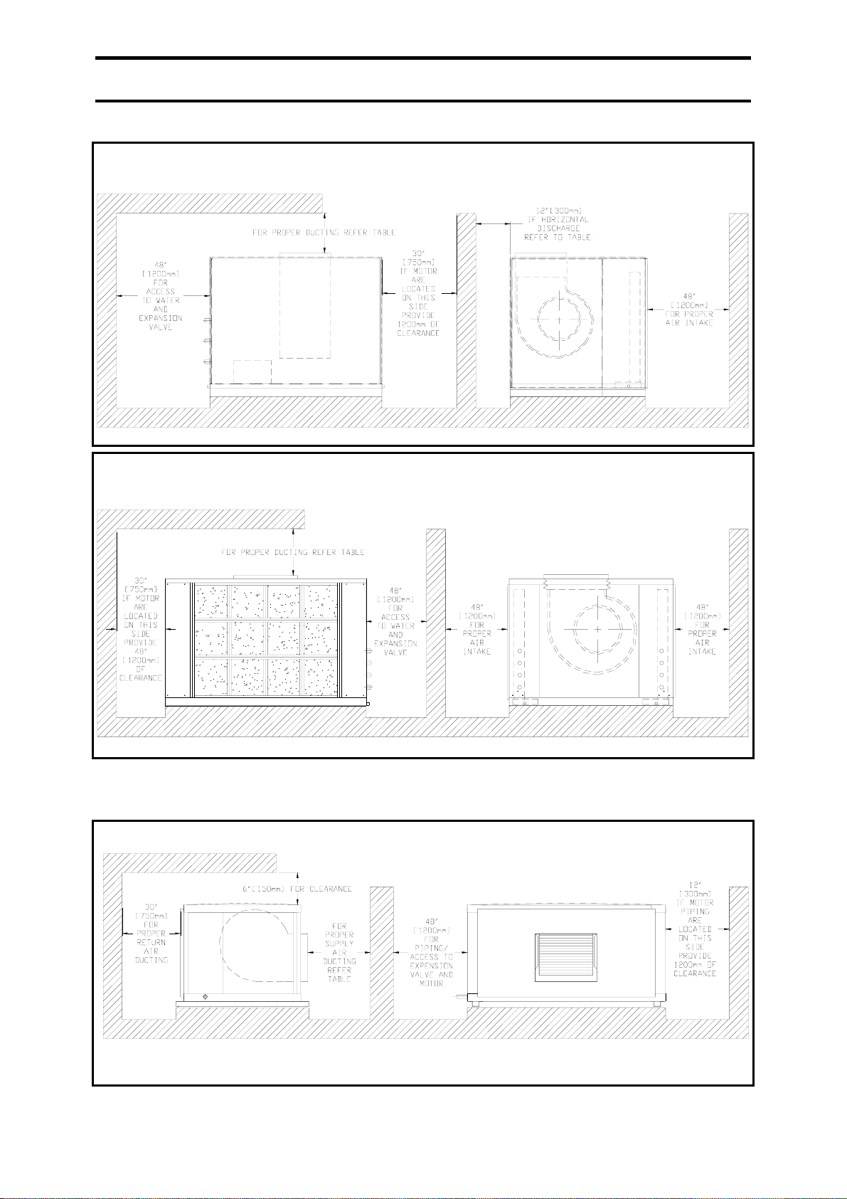
3.0 INSTALLATION
b.) EB 250D, 290D, 320D, 380D, 435D, 480D, 510D, 570D, 640D, 700D, 760D
c.) EB 800D, 890D, 960D, 1020D, 1140D, 1340D, 1520D.
3.4.2. HORIZONTAL CASING TYPE- HEB
HEB 68D, 81D, 95D, 108D, 125D, 145D, 160D, 190D, 220D
10
Page 11
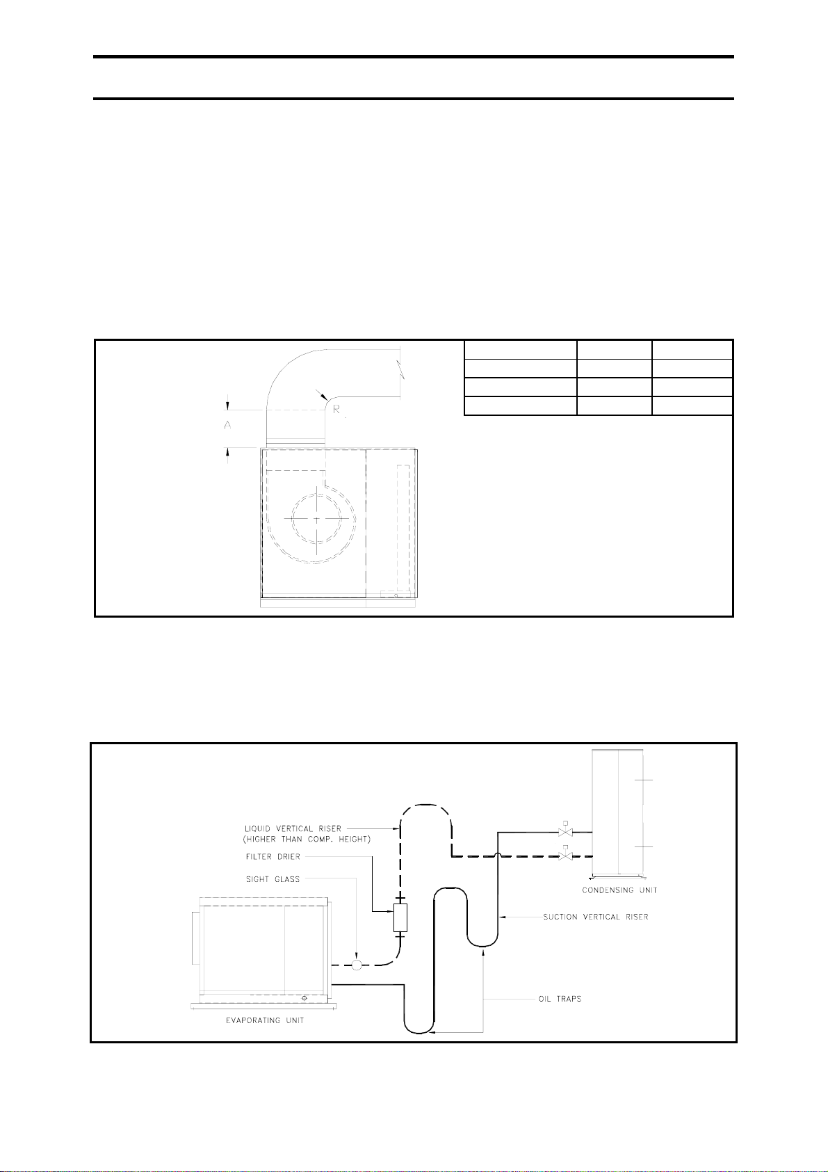
3.0 INSTALLATION
3.5 DUCT CONNECTIONS
All ducts shall be made according to local and/
or national codes and also with good duct
installation practice. Minimize static losses by
limiting the number of bends.
Suspended duct work with flexible hangers
shall not be fastened directly to the unit.
A length of straight duct shall be installed as
per Figure 3.5. This is to ensure uniform flow
of discharge air. If an elbow need to be
installed, then it shall be 1.5 of equivalent duct
diameter. (Equivalent duct Ø= (4ab/π)
0.5
).
Please refer to AMCA standard for proper
ducting installation/ guidelines.
FIGURE 3.5: SUGGESTED METHOD FOR CONNECTING SUPPLY DUCT
Model A R
HEB/EB 68D – 125D 40”[1016mm] 25”[635mm]
HEB/EB 160D – 760D 60”[1524mm] 35”[889mm]
EB 800D – 1520D 80”[2032mm] 50”[1270mm]
Note: Transition element shall not be greater than 15° for converging elements nor greater 7° for diverging element.
3.6 FIELD PIPING
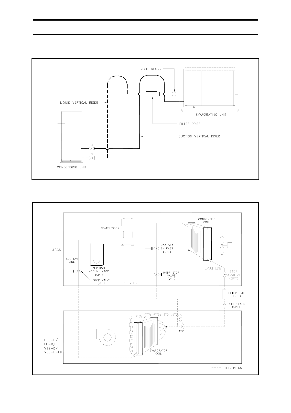
1.) COMPRESSOR (CONDENSING UNIT) IS ABOVE THE EVAPORATING UNIT.
Note: Traps should be provided for every 20 ft [6.1m] of vertical riser for proper oil movement.
11
Page 12
3.0 INSTALLATION
2.) EVAPORATING IS ABOVE THE COMPRESSOR.
Note : Traps should be provided for every 20ft [6.1m] of vertical riser for proper oil movement.
3a.) TYPICAL PIPING SCHEMATIC (WITH OPTIONAL ACCESSORY AS INDICAT ED)
12
Page 13
3.0 INSTALLATION
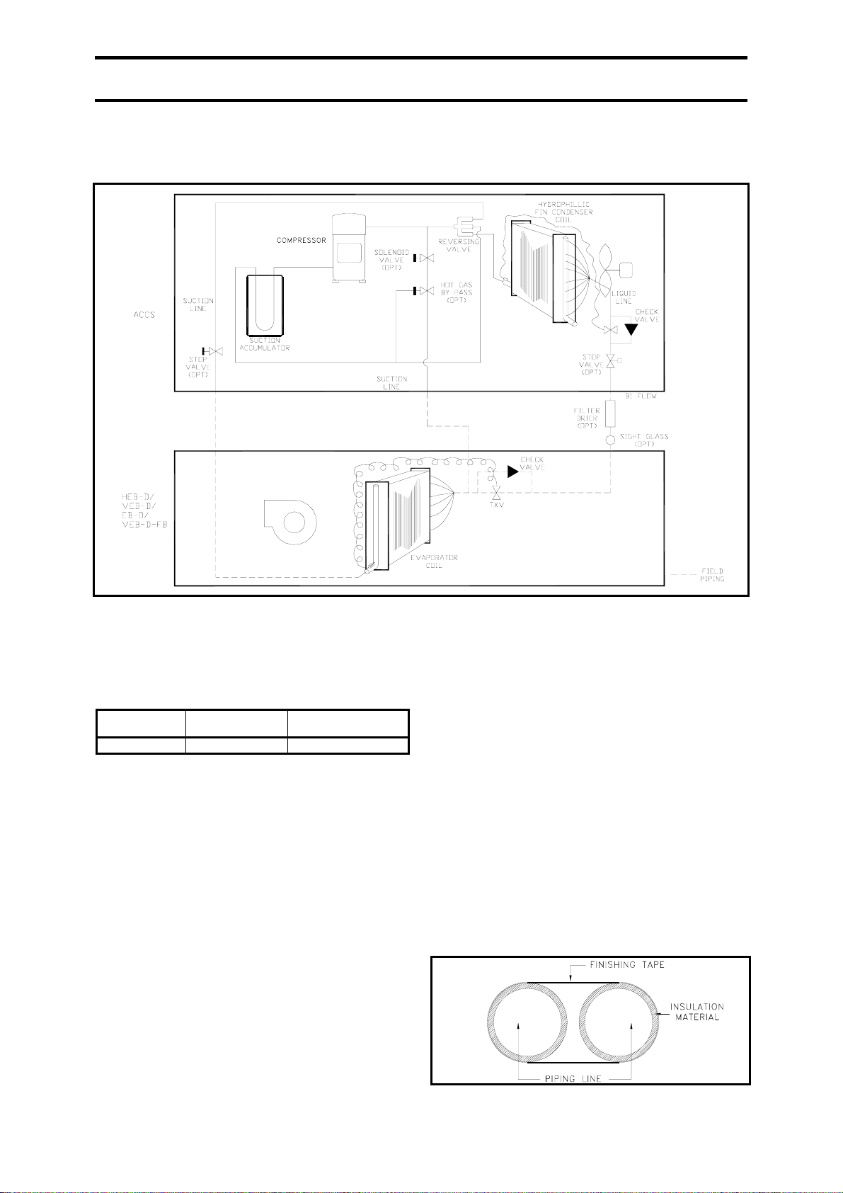
3b.) TYPICAL PIPING SCHEMATIC – HEAT PUMP (WITH OPTIONAL ACCESSORY
AS INDICATED)
3.7 REFRIGERANT PIPING
1.) Prior to connecting the tubes, make sure to
apply blind caps or water proof tape to
prevent dust or water from getting into the
tubes.
Model Max. Allowable
Piping Length (L)
ACCS 68-1520 75 ft 30 FT
2.) Horizontal discharge and suction lines
should be sloped in the direction of flow at
a rate of 1” [25.4mm] for every 20ft [6.1m]
in order to aid oil drainage. If there is a
vertical riser of more than 5ft [1.5m] on
the suction line, there should be a trap at
the bottom. For long suction vertical riser,
additional trap is recommended for each
20ft [6.1m] of riser to insure proper oil
return.
3.) The suction and liquid line should be sized
according to the manufacturers standard.
4.) Minimize the exposure time to atmosphere
during brazing.
5.) Drain pipe size should be the same or
bigger than the existing pipe. The pipe
should be installed in downward slope so
that water is drained by gravity. A trap
Elevation Difference
Between Two Units
must be provided on the pipe so that
condensate will drain and not overflowing
the drain pan. In addition, upon start-up,
the water will not be sucked by the blower.
In addition, the evaporator coil is located
before the intake of the centrifugal blowers
and operates below atmospheric pressure.
Thus, to compensate for this pressure
differential, a trap is required.
6.) Suction line must be insulated to prevent
condensation. It is also suggestable to
insulate the liquid line. Insulating these
line will prevent unnecessary heat losses/
gains.
7.) This unit is designed to run up to max pipe
length (single distance) 75ft [22.9m]. For
length exceeding 75ft [22.9m], consult
factory for assistance (piping size need to
be changed and oil need to be added.).
13
Page 14

3.0 INSTALLATION
3.8 LEAK TEST (SYSTEM
PRESSURE TEST)
1.) Leak test pressure is at 200psig
[1380kPa]. Disconnect or shut off all
devices which may be damaged by
200psig [1380 kPa] test pressure.
2.) Open all valves in system so that entire
system can be pressurized and connect
refrigerant cylinder to charging
connection.
3.) Charge in freon vapor to the system until
50psig [345 kPa] and then pressurize with
dry nitrogen until 200psig [1380 kPa].
Stop charging gas if noise of escaping gas
is heard. Skip to sequence (6.)
Caution: Always use inert gas such as
nitrogen for testing. Never use other gases
such as Oxygen or acetylene which may
be inflammable.
4.) With pressure at 200psig [1380kPa], shut
off the valve connecting nitrogen cylinder
to the system. Disconnect nitrogen
cylinder and leave pressure gauge
indicating 1380kPa connected to system.
5.) With halide torch or electronic leak
detector, leak check every valve, joint,
pressure control, coils and headers. Mark
every leak and record down as remarks.
6.) When all leaks have been found, blow off
charge through tube to outside to prevent
refrigerant accumulation around the
system.
7.) Repair all leaks (check off on your
remarks): If rebrazing is required, feed
nitrogen through into the system at
slightly excessive pressure (leave system
open and make sure nitrogen flows
through).
8.) After repairing leaks, re-check as per
procedure 1 through 7.
9.) When system tight after leak test, keep
pressurized at 200psig [1380kPa] and
hold for 12 hours. Full in pressure should
be negligible (some may be due to
temperature change only.)
10.) When system is tight, proceed with
vacuum test and dehydration.
3.9 VACUUM TEST AND
DEHYDRATION
The purpose of evacuation is to evacuate the
system when it is known or suspected that the
system has been exposed to atmosphere, and
there is a possibility that moisture has entered
the system.
1.) Blow-off charge or pump down the
refrigerant.
2.) Connect vacuum pump the liquid line
valve and carefully check the unit piping to
ensure all passages are open. (NEVER
USE SYSTEM COMPRESSOR TO
EVACUATE).
3.) Start vacuum pump operation and pull
vacuum to about 2 to 2.5mmHg [0.26 to
0.33 kPa] absolute pressure. During
evacuation the pressure may remain steady
for sometime at about 0.5” or 12mmHg
[1.69 kPa] absolute pressure. This is
caused by moisture evaporating in the
system. This "boiling off" or "evaporation
period" last about the same period of time
as it took from initial start to reach this
point.
4.) When the "boiling off" period lasts longer
that indicated under 3, break vacuum with
refrigerant or nitrogen gas to sweep
moisture out and evacuate and dryer shells,
etc., up to a temperature of 100°F
[37.8°C].
5.) Break vacuum with refrigerant or nitrogen
gas until pressure is 0psig [0 kPa].
6.) Re-evacuate to 1mmHg [0.133kPa]
absolute pressure.
7.) Disconnect vacuum pump and leave
system standing for 6 hours. There should
be no change in vacuum during this period.
If there is a change repeat 1 to 7.
14
Page 15

3.0 INSTALLATION
3.10 INSTALLATION OF
DRIERS OR SIGHT
GLASS
1.) Break vacuum with nitrogen.
2.) When permanently brazed drier or sight
glass is used, open one valve on system to
atmosphere while maintaining slight
nitrogen flow.
3.) When flare connected drier or sight glass is
used, use similar procedure as under 2.
However, no valve need to be left open to
atmosphere.
4.) When replaceable dryer core is used follow
procedure as under 3. Insert drier core(s).
Tighten cap screws.
5.) Re-evacuate system to 1mmHg [0.133
kPa] absolute.
3.11 CHARGING
1.) Connect refrigerant cylinder through
charging connection to charging valve.
2.) Loosen flare nut on other end of charging
connection and blow air out with
refrigerant. Tighten flare nut on charging
connection.
3.) Weight refrigerant cylinder.
4.) Open charging valve and charge in
refrigerant vapor through suction access
valve until about 150psig [1034 kPa].
Switch to liquid line access valve and
charge in liquid refrigerant. Continue
charging with liquid refrigerant until clear
glass is observed.
5.) Shut off refrigerant charging valve but
keep connected. Check charging valve
flare nut for leak. Check and record down
discharge and suction pressure. If more
than one system to be charged, follow
procedure 1 through 4 for each system.
After all the systems have been done up to
step 4, proceed with 5 and 6.
6.) Shut off the system (compressor, fans,
pumps) and leave for 24 hours.
3.12 LUBRICATION
The scroll compressor use mineral oil 3GS, for
R22 compressors and POE (Polyol ester) oil
for HFC refrigerants (R134a, R407c etc)
compressors. Please refer to compressor name
plate for original oil charge. Recharge shall be
118ml less than the original charge. The
condenser fan used a direct-drive permanent
split capacitor motor. The motor should be
lubricated with 30 to 40 drops of SAE #20
non-detergent oil as follows depending on
service:
LIGHT DUTY -After 25,000 operating
hours.
NORMAL DUTY -Annually after three years
or 8,000 operating hours.
HEAVY DUTY -Annually after one year
or at least every 1500 operating hours.
CAUTION: DO NOT OVER OIL
3.13 SENSING BULB
LOCATION
1.) Sensing bulb is not installed for the
evaporator unit due to limited space and
for precautionary reasons.
2.) The sensing bulb should be attached to a
horizontal suction line at the evaporator
outlet.
3.) If more than one TXV is used on
evaporator sections, make sure that the
sensing bulb of each valve is applied to the
suction line of the evaporator fed by that
valve.
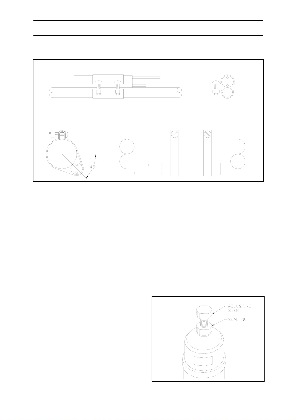
4.) On suction lines 7/8” [22.2mm] OD and
larger, it is recommended that the bulb be
installed at 4 or 8 o’clock on the side of the
horizontal line and parallel with respect to
the direction of flow. On smaller lines, the
bulb should be mounted on the top of the
line. See Figure 3.13.
15
Page 16
3.0 INSTALLATION
FIGURE 3.13: REMOTE BULB
1. Remote Bulb Small Suction Line (Smaller Than 7/8” [22.2mm])
2. Remote Bulb On large Suction Line (7/8” [22.2mm] and Larger)
5.) For good thermal contact, the bulb should
be securely fastened with two bulb straps
to a clean, straight section of the suction
line. It should be insulated with cork tape
to prevent the effect of surrounding
environment.
3.14 EXTERNAL EQUALIZER
CONNECTION
The equalizer connection should be made at a
point that will most accurately reflect the
pressure existing in the suction line at the bulb
location. Generally, the connection is as close
to bulb on the downstream side.
3.15 HOT GAS BYPASS
The purpose of the hot gas by pass is to create
artificial load in the system by means of
injecting hot gas into the inlet of the
distributor. This would prevent the suction
pressure from falling below the desired
settings and thus causing frequent compressor
cycling. The valve is pressure actuated, where
it allows the discharge gas to bypass if the
downstream pressure is below the setting. The
setting could be changed by adjusting the stem
on the valve body. To set the pressure, loose
the seal nut as shown below and turn the
adjusting stem clockwise to raise the pressure
or counter clockwise to lower the pressure.
One turn of the stem equals to 16psig
[110.3kPa]. The adjustment range for the valve
is between 10”Hg [33.8kPa] to 120psig [827
kPa].
It is important that the setting to be performed
under actual operating condition, i.e. under
minimal system load conditions so that it could
maintain the minimum desired suction
pressure. Hot gas flow could be detected by
listening the gas flowing through the valve or
by touching the outlet pipe.
16
Page 17
3.0 INSTALLATION
3.17 TIGHTENING OF
PULLEY SET SCREW
Apply one or two drops of thread locked 243
to the engagement area of set screws before
tightening the pulleys according to the
recommended torque.
Set Screw Size Tightening Torque
5/16” [7.9mm] 10 Lbs.ft [13NM]
3/8” [9.5mm] 19 Lbs.ft [26NM]
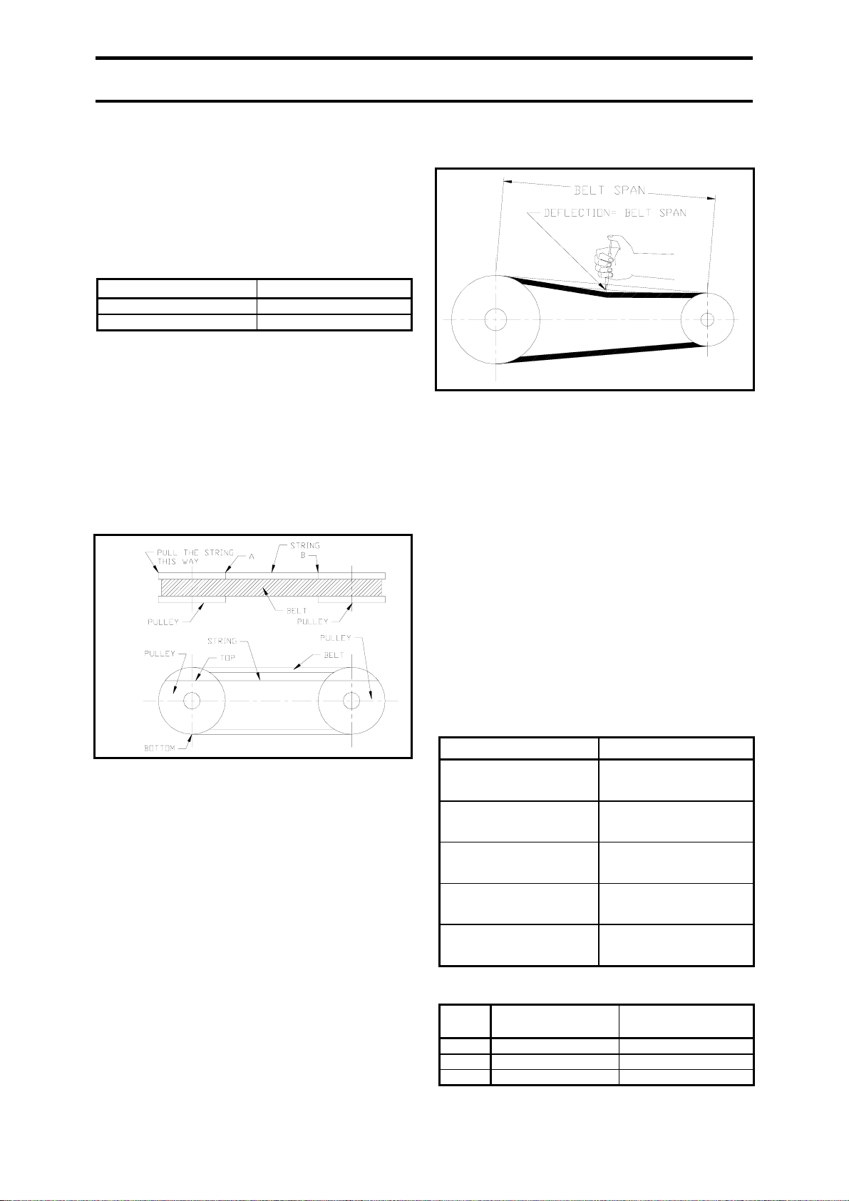
3.18 PULLEY ALIGNMENT
1.) Insert one end of the string inside the gap
between belt and pulley.
2.) Rotate the pulley so that string is clipped
between the pulley and the belt.
3.) Pull the other end of the string as per
figure below.
FIGURE 3.17:
4.) Inspect for any gap between the string and
pulley at A and B.
5.) If find any gap then adjust either pulley to
make the gap as small as possible.
6.) Repeat steps 1, 2, 3, 4 and 5 for bottom of
the same side, top and bottom of the other
side. (As shown as Figure 3.17)
3.18 BELT TENSION
INSPECTION GUIDE
1.) Measure the belt span (See Figure 3.18).
2.) Position of the “O” ring on the span scale
at the measure belt.
3.) Set the “O” ring on the deflection force
scale to zero.
FIGURE 3.18: BELT SPAN
4.) Place the tension meter squarely on the
belt at the belt span. Apply a force on the
plunger and perpendicular to the belt span
until the bottom of the “O” ring even the
top of the next belt or with the bottom of a
straight edge laid across the sheaves.
5.) Remove the tension meter and read the
force applied from the bottom of the “O”
ring on the deflection force scale.
6.) Compare the force you have applied with
the values in Table 3.18a and 3.18b.
Note: A new drive should be tensioned to the
higher value. After the drive has been running
for 30 minutes, the tension should be checked
and readjust to the higher value, if necessary.
Table 3.18a:
Belt Span Lt (cm) Deflection Td (cm)
25 – 30
31 – 36
37 – 42
43 – 48
49 – 54
55 – 60
61 – 66
67 – 72
55 – 60
79 – 84
85 – 90
91 – 96
97 – 102
103 – 108
109 - 114
0.4
0.5
0.6
0.7
0.8
0.9
1.0
1.1
1.2
1.3
1.4
1.5
1.6
1.7
1.8
Table 3.18b:
Belt
Type
Small Pulley Diameter –
inches [mm]
A 3.0 - 5.5 [76 – 140] 2.2 – 3.3 [1.0 - 1.5]
B 5.0 - 8.0 [127 – 203] 4.4 – 6.8 [2.0 - 3.1]
C 8.0 - 16.0 [203 – 406] 9.0 – 13.4 [4.1 - 6.1]
Maximum Deflection –
lbs [Kg]
17
Page 18

4.0 OPERATION
4.1 PHASE ROTATION
Avoid running in reverse rotation. If during
initial start up the compressor does not build
up pressure, noise is abnormally loud and
power consumption is minimal, then there is a
possibility that the unit is operating at reverse
rotation. Shut down the power and connect
phase to the proper terminals. Running reverse
may damage the compressor (s).
4.2 CYCLE LIMIT RATE
Each compressors must not be cycle on-off for
more than 12 times per hour. The higher
number of starts per hour will reduce the life of
the compressor. Thus, it is suggested that anti
short cycle timer is provided in the system.
4.3 FAN CYCLING
(OPTIONAL,
STANDARD FOR HEAT
PUMP)
During cooling only, the head pressure control
would allow the unit to operate at lower
ambient temperature by building up the
discharge pressure through cycling of fans (for
single fan unit, this is achievable by reducing
the fan speed). If there is demand for cooling.
The unit would run on cooling until the manual
charge over is set to heating. Please observe
the lowest ambient for cooling mode. For heat
pump units fan cycling is standard.
4.4 DEFROST CYCLE
(STANDARD FOR
HEAT PUMP)
During heating, a defrost controller would
initiate the defrost cycle once there is demand
for it. The sensor from the controller would
sense the suction pressure and if the pressure is
lower then the preset value, Then a signal
would be sent to the control panel which then
relay the signal to the reversing valve to
reverse the cycle. Now, the outdoor coil would
be discharging hot air and defrosting the ice on
the fins surface. The standard factory set timer
for the defrost cycle is 10 minutes which could
be adjusted according to the site condition.
4.5 CRANKCASE HEATER
(STANDARD FOR
HEAT PUMP)
Refrigerant tend to migrate to colder section of
the unit. During winter, the compressor
compartment is at lower temperature than the
evaporator and thus refrigerant tend to
accumulate in the compressor compartment.
Connect power source to the unit a few hours
prior to compressor start up so that the
refrigerant would be forced out of the
compressor compartment. It is good practice to
let the crankcase heater to be energized
continuously, independent of compressor
operation.
4.6 STOP VALVE
Inspect all stop valves prior to start up. They
shall be in open position.
4.7 HYDROPHILIC
CONDENSER COIL
(STANDARD FOR
HEAT PUMP)
Hydrophilic fins assist condensation to be
removed faster and therefore reduced the
possibility of icing on the coil.
4.8 STAINLESS STEEL
BOLTS AND NUTS
Reduce the possibility of corrosion especially
when the environment is corrosive.
18
Page 19
4.0 OPERATION
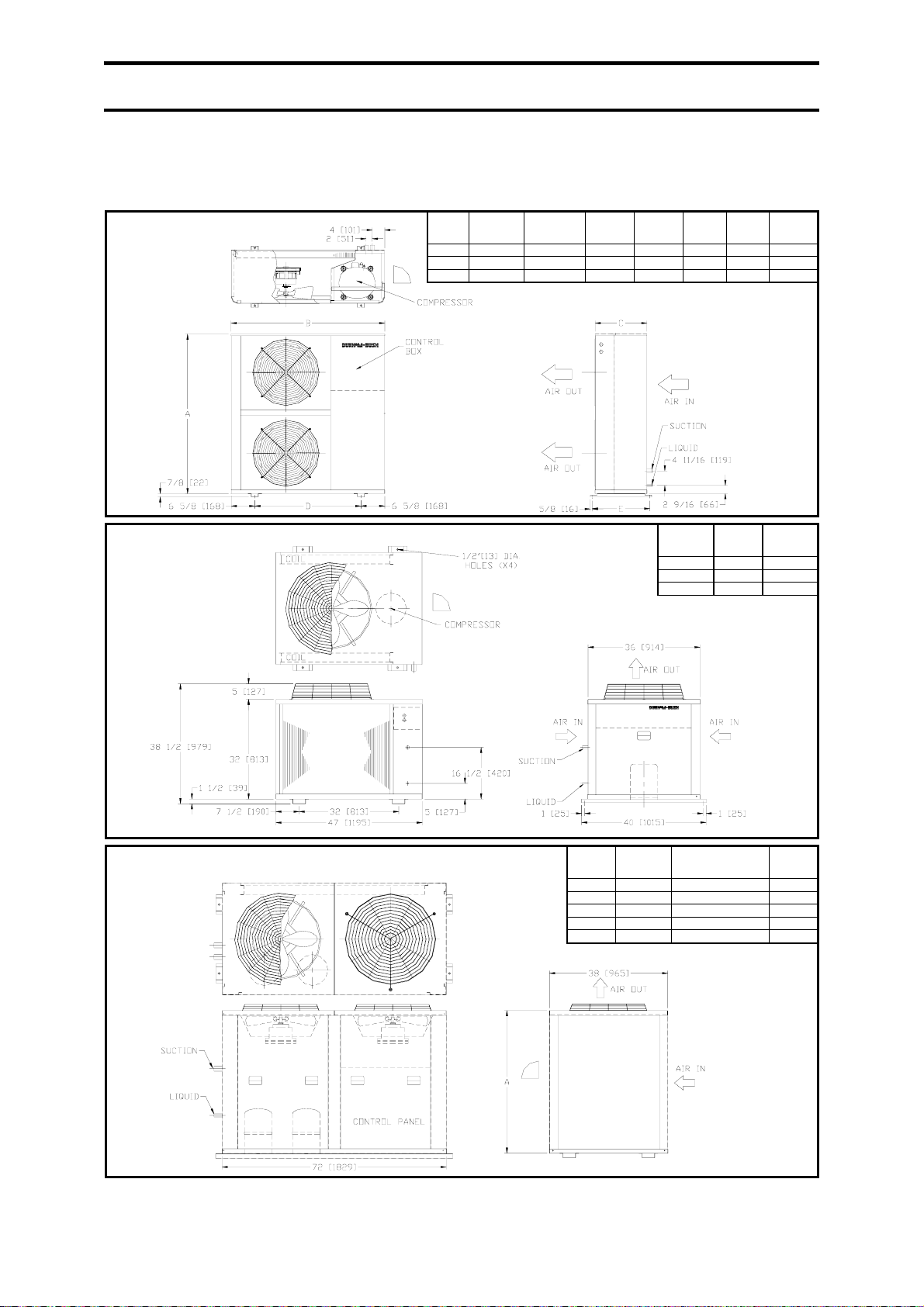
4.9 DIMENSIONAL DATA
1.) Air Cooled Condensing Units
ACCS 68, 81, 95
ACCS 108, 125, 145
MODEL A B C D E
ACCS 68
46 1/2[1181] 42 11/16[1084] 14 3/8[365] 29 7/16[748] 15 3/4[400] 7/8[22] (1) 3/8[10] (1)
ACCS 81
48 1/2[1232] 44 3/8[1127] 19 5/16[491] 35 1/4[895] 20 7/8[530] 7/8[22] (1) 1/2[13] (1)
ACCS 95
48 1/2[1232] 44 3/8[1127] 19 5/16[491] 35 1/4[895] 20 7/8[530] 7/8[22] (1) 1/2[13] (1)
OTE: ACCS 68 IS WITH SERVICE VALVE.
MODEL
ACCS 108
ACCS 125
ACCS 145
1 3/8[35] (1) 1/2[13] (1)
1 3/8[35] (1) 1/2[13] (1)
1 3/8[35] (1) 5/8[16] (1)
SUCTION
SIZE
(QTY)
SUCTION
SIZE
(QTY)
LIQUID
SIZE
(QTY)
LIQUID
SIZE
(QTY)
ACCS 160, 190, 220, 250, 290
ACCS 160
ACCS 190
ACCS 220
ACCS 250
ACCS 290
NOTE : ALL DIMENSIONS ARE IN INCHES.
MODEL A
40 1/4[1016] 1 3/8[35] (1) 5/8[16] (1)
40 1/4[1016] 1 5/8[41] (1) 5/8[16] (1)
48 1/4[1219] 1 3/8[35] (1), 1 1/8[29] (1) 1/2[13] (2)
48 1/4[1219] 1 3/8[35] (2) 1/2[13] (2)
48 1/4[1219] 1 3/8[35] (2) 5/8[16] (2)
NOTE: ACCS 160 AND 190 ARE SINGLE COMPRESSOR
UNIT.
SUCTION SIZE
(QTY)
LIQUID
SIZE
(QTY)
19
Page 20
4.0 OPERATION
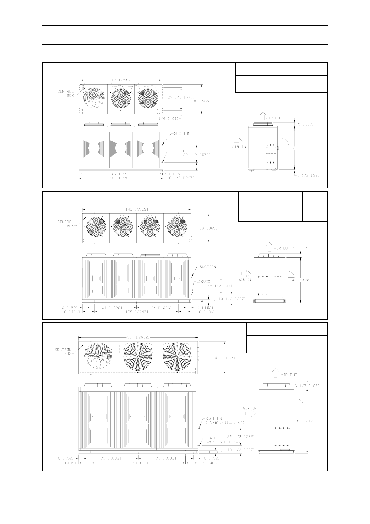
ACCS 320, 380, 435
ACCS 320
ACCS 380
ACCS 435
ACCS 480, 510, 570
ACCS 480
ACCS 510
ACCS 570
ACCS 640, 700, 760
NOTE : ALL DIMENSIONS ARE IN INCHES.
MODEL
MODEL
A SUCTION
SIZE (QTY)
48[1219] 1 3/8[35] (2) 5/8[16] (2)
56[1422] 1 5/8[41] (2) 5/8[16] (2)
56[1422] 1 3/8[35] (3) 5/8[16] (3)
SUCTION SIZE (QTY) LIQUID SIZE
1 3/8[35] (3) 5/8[16] (3)
1 5/8[41] (1), 1 3/8[35] (2) 5/8[16] (3)
1 5/8[41] (3) 5/8[16] (3)
MODEL
ACCS 640
ACCS 700
ACCS 760
SUCTION SIZE (QTY) LIQUID
1 3/8[35] (4) 5/8[16] (4)
1 3/8[35] (2), 1 5/8[41] (2) 5/8[16] (4)
1 5/8[41] (4) 5/8[16] (4)
LIQUID SIZE
(QTY)
(QTY)
SIZE (QTY)
20
Page 21
4.0 OPERATION
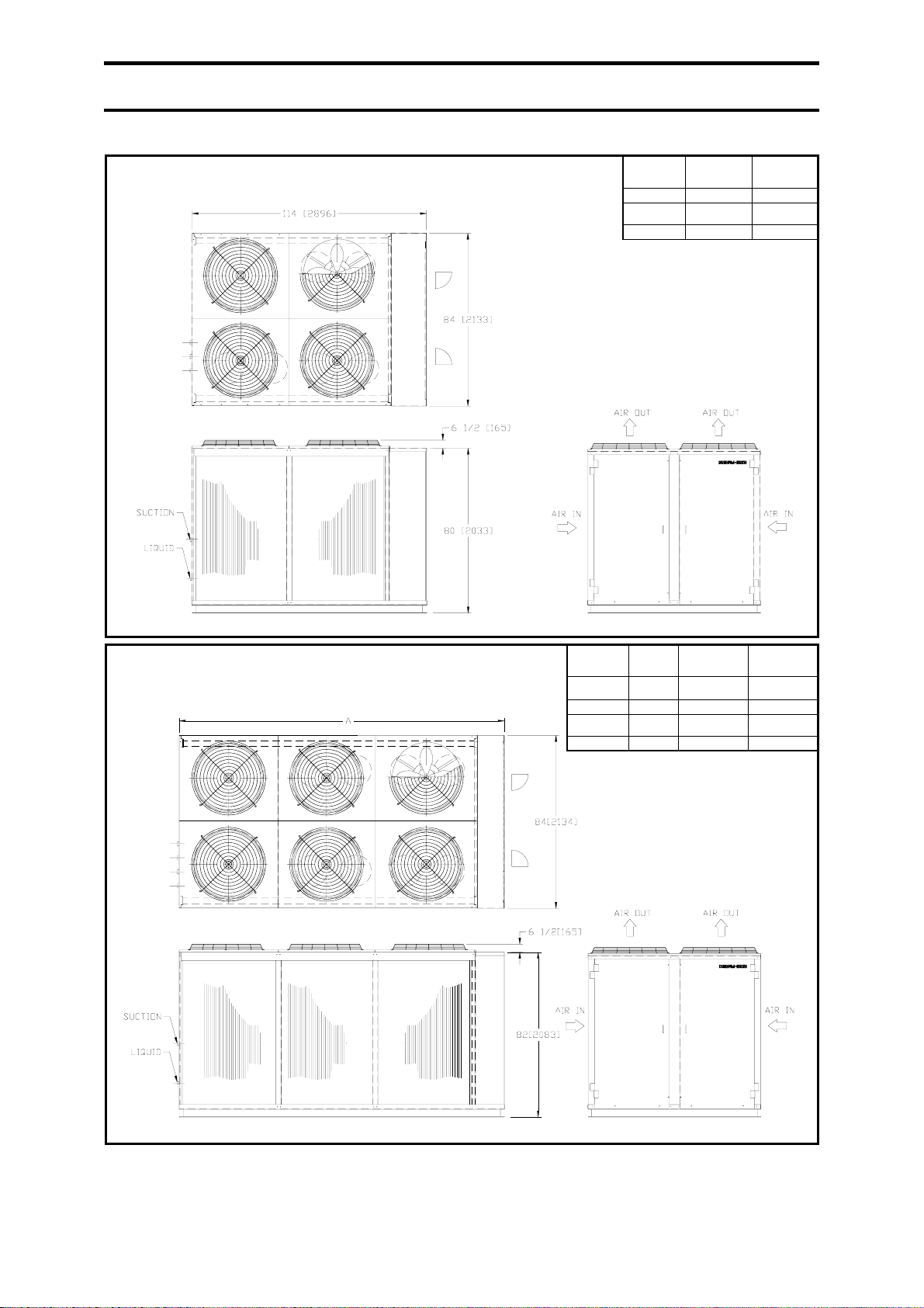
ACCS 800, 890, 960
ACCS 1020, 1140, 1340, 1520
MODEL SUCTION SIZE
MODEL A SUCTION SIZE
ACCS 1020
ACCS 1140
ACCS 1340
ACCS 1520
ACCS 800
ACCS 890
ACCS 960
143[3632] 1 5/8[41] (2)
143[3632] 2 1/8[54] (3) 7/8]22] (3)
150[3810] 1 5/8[41] (3)
150[3810] 2 1/8[54] (4) 7/8[22] (4)
(QTY)
1 3/8[35] (5) 5/8[16] (5)
1 3/8[35] (2),
1 5/8[41] (3)
1 5/8[41] (3) 7/8[22] (3)
(QTY)
2 1/8[54] (1)
2 1/8[54] (1)
LIQUID SIZE
(QTY)
5/8[16] (5)
LIQUID SIZE
(QTY)
7/8[22] (3)
7/8[22] (4)
NOTE: ALL DIMENSIONS ARE IN INCHES.
21
Page 22
4.0 OPERATION
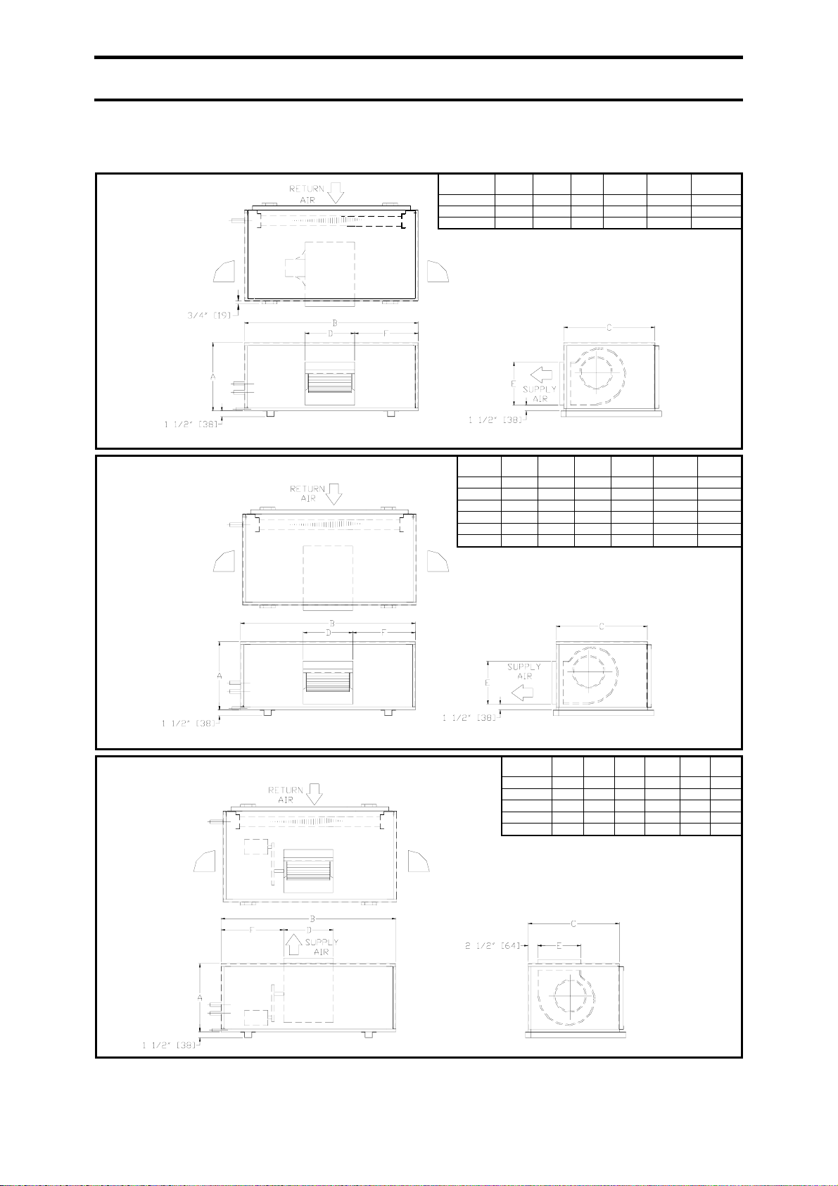
Evaporator Units
HEB 68D, 81D, 95D
HEB 68D
HEB 81D
HEB 95D
MODEL
HEB 108D, 125D, 145D, 160D, 190D, 220D
HEB 108D
HEB 125D
HEB 145D
HEB 160D
HEB 190D
HEB 220D
MODEL
EB 250D, 290D, 320D, 380D, 435D
EB 250D
EB 290D
EB 320D
EB 380D
EB 435D
NOTES. : 1.) ALL DIMENSIONS ARE IN INCHES.
2.) UNITS SHOWN ARE RIGHT HAND PIPING CONNECTION.
A B C D E F
20[508] 46[1168] 24[610] 13[330] 11 3/8[289] 16 1/2[419]
20[508] 46[1168] 24[610] 13[330] 11 3/8[289] 16 1/2[419]
23[584] 46[1168] 30[762] 15 1/2[394] 13 1/2[343] 15 1/4[387]
27[686] 50[1270] 33[838] 15 1/2[394] 13 1/2[343] 21 1/4[540]
27[686] 50[1270] 33[838] 15 1/2[394] 13 1/2[343] 21 1/4[540]
27[686] 50[1270] 33[838] 15 1/2[394] 13 1/2[343] 21 1/4[540]
29[737] 58[1448] 40[1016] 18 1/2[470] 16[406] 24 3/8[619]
29[737] 58[1448] 40[1016] 18 1/2[470] 16[406] 24 3/8[619]
29[737] 78[1981] 40[1016] 18 1/2[470] 16[406] 30[762]
MODEL
A B C D E F
A B C D E F
29[ 78 40 18 1/2 16 30
38 84 45 17 19 33 1/2
38 84 45 17 19 33 1/2
48 84 45 22 19 37
48 84 45 22 1/2 22 1/2 37
22
Page 23
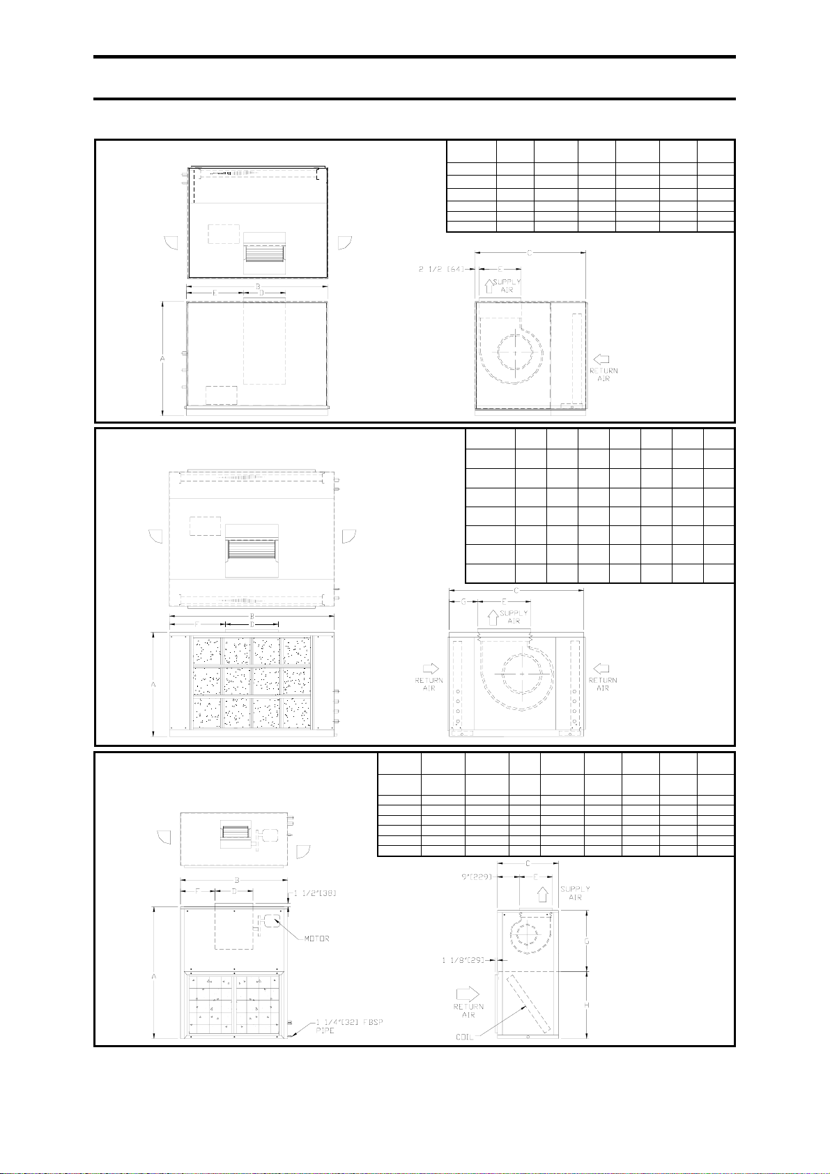
4.0 OPERATION
EB 480D, 510D, 570D, 640D, 700D, 760D
EB 480D
EB 510D
EB 570D
EB 640D
EB 700D
EB 760D
EB 800D, 890D, 960D, 1020D, 1140D,
1340D, 1520D
VEB 108D, 125D, 145D, 160D, 190D,
220D, 250D
VEB 125D
VEB 145D
VEB 160D
VEB 190D
VEB 220D
VEB 250D
NOTES. : 1.) ALL DIMENSIONS ARE IN INCHES.
2.) UNITS SHOWN ARE RIGHT HAND PIPING CONNECTION.
Model A B C D E F G H
VEB 108D
MODEL A B C D E F
51 1/2[1308] 52 [1321] 25[635] 15 1/2[394] 13 1/2[343] 17 1/4[438] 25 3/4[654] 25 3/4[654]
51 1/2[1308] 52[1321] 25[635] 15 1/2[394] 13 1/2[343] 17 1/4[438] 25 3/4[654] 25 3/4[654]
51 1/2[1308] 52[1321] 25[635] 15 1/2[394] 13 1/2[343] 17 1/4[438] 25 3/4[654] 25 3/4[654]
57 1/2[1461] 58 1/2[1486] 28[711] 18 5/8[473] 16[406] 15[381] 28 3/4[730] 28 3/4[730]
57 1/2[1461] 58 1/2[1486] 28[711] 18 5/8[473] 16[406] 15[381] 28 3/4[730] 28 3/4[730]
57 1/2[1461] 68[1727] 28[711] 15 1/2[394] 16[406] 26[660] 28 3/4[730] 28 3/4[730]
57 1/2[1461] 68[1727] 28[711] 18 1/2[470] 16[406] 24 3/4[629] 28 3/4[730] 28 3/4[730]
68[1727] 84[2134] 66[1676] 25[635] 25[635] 34[864]
68[1727] 84[2134] 66[1676] 25[635] 25[635] 34[864]
68[1727] 84[2134] 66[1676] 25[635] 25[635] 34[864]
78[1981] 84[2134] 66[1676] 28[711] 28[711] 34[864]
78[1981] 84[2134] 66[1676] 28[711] 28[711] 34[864]
78[1981] 84[2134] 66[1676] 28[711] 28[711] 34[864]
MODEL A B C D
EB 800D
EB 890D
EB 960D
EB 1020D
EB 1140D
EB 1340D
EB 1520D
62
98
[2489]
98
[2489]
98
[2489]
98
[2489]
98
[2489]
118
[2997]
118
[2997]
80
[2032]
80
[2032]
80
[2032]
80
[2032]
80
[2032]
86
[2184]
86
[2184]
[1575]
62
[1575]
62
[1575]
62
[1575]
62
[1575]
70
[1778]
70
[1778]
31 1/2
[800]
31 1/2
[800]
31 1/2
[800]
35 1/2
[902]
35 1/2
[902]
40
[1016]
40
[1016]
E
31 1/2
[800]
31 1/2
[800]
31 1/2
[800]
35 1/2
[902]
35 1/2
[902]
40
[1016]
40
[1016]
F G
39
17
[991]
[432]
39
17
[991]
[432]
39
17
[991]
[432]
39
14
[991]
[356]
39
14
[991]
[356]
39
14
[991]
[356]
39
14
[991]
[356]
23
Page 24
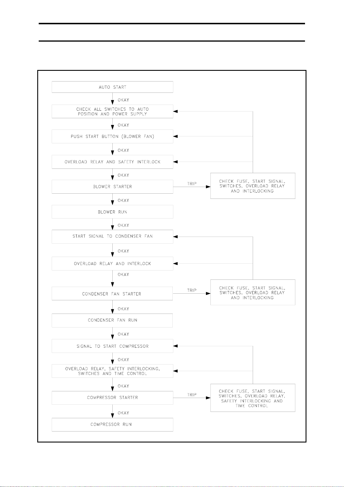
4.0 OPERATION
4.10 TYPICAL OPERATING SEQUENCE
24
Page 25
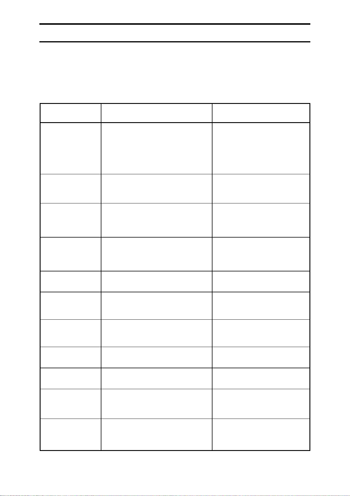
5.0 MAINTENANCE
5.1 MAINTENANCE
These units are designed to provide years of
services with minimum maintenance.
Nonetheless, it is a good practice to carry out
ITEM MAINTENANCE PROCEDURE RECOMMENDED SCHEDULE
regular inspection and checking to ensure the
unit's optimum performance and compliance
with local rules and regulations.
Air Filters 1. Washable type.
2. Clean with a vacuum cleaner or tapped
lightly and then wash in luke warm
water (below 104°F [40°C]).
3. Make sure the filter is dry.
Belt 1. Check the tension and alignment.
2. Move the motor if the belt is loose.
Pulley 1. Make sure the set screws are properly
tightened and there is no crack on the
pulley.
Blower 1. Turn the blower manually. It should run
smoothly and there is no excessive
bearing noise.
Bearing and Shaft 1. Check for evidence of wear. Once a year.
Bolts, Screws and
Nuts.
1. Tighten any loose components. Once a year.
Once a month or depending
upon the condition of the
circulated air.
Once every six months.
Once every six months.
Once every six months.
Coil 1. Check and remove clogged item
between fins.
Paint 1. Check any evidence of corrosion. Once a year.
Compressor 1. Check if there is any leakage. Every six months.
Electrical 1. Check voltage, current and wiring.
2. Check connections.
Drain Pan and Pipe 1. Pour some water into the drain pan
and let the water run through. If the
pipe is clogged, remove the dirt.
Once a year.
Every two months.
Every six months.
25
Page 26
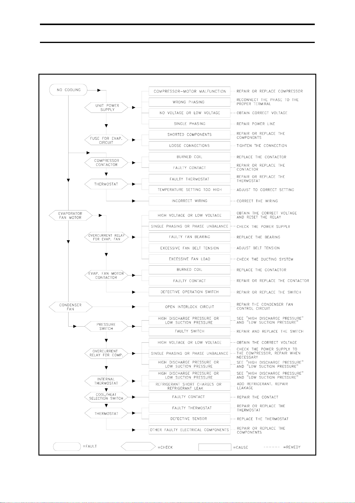
5.0 MAINTENANCE
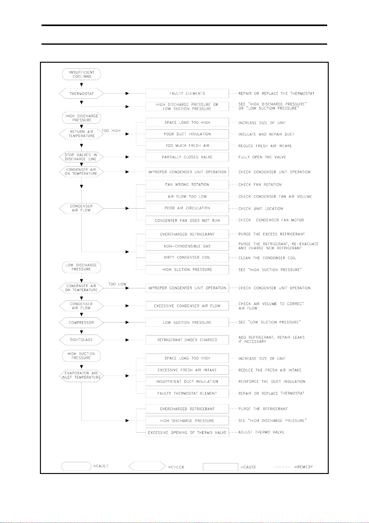
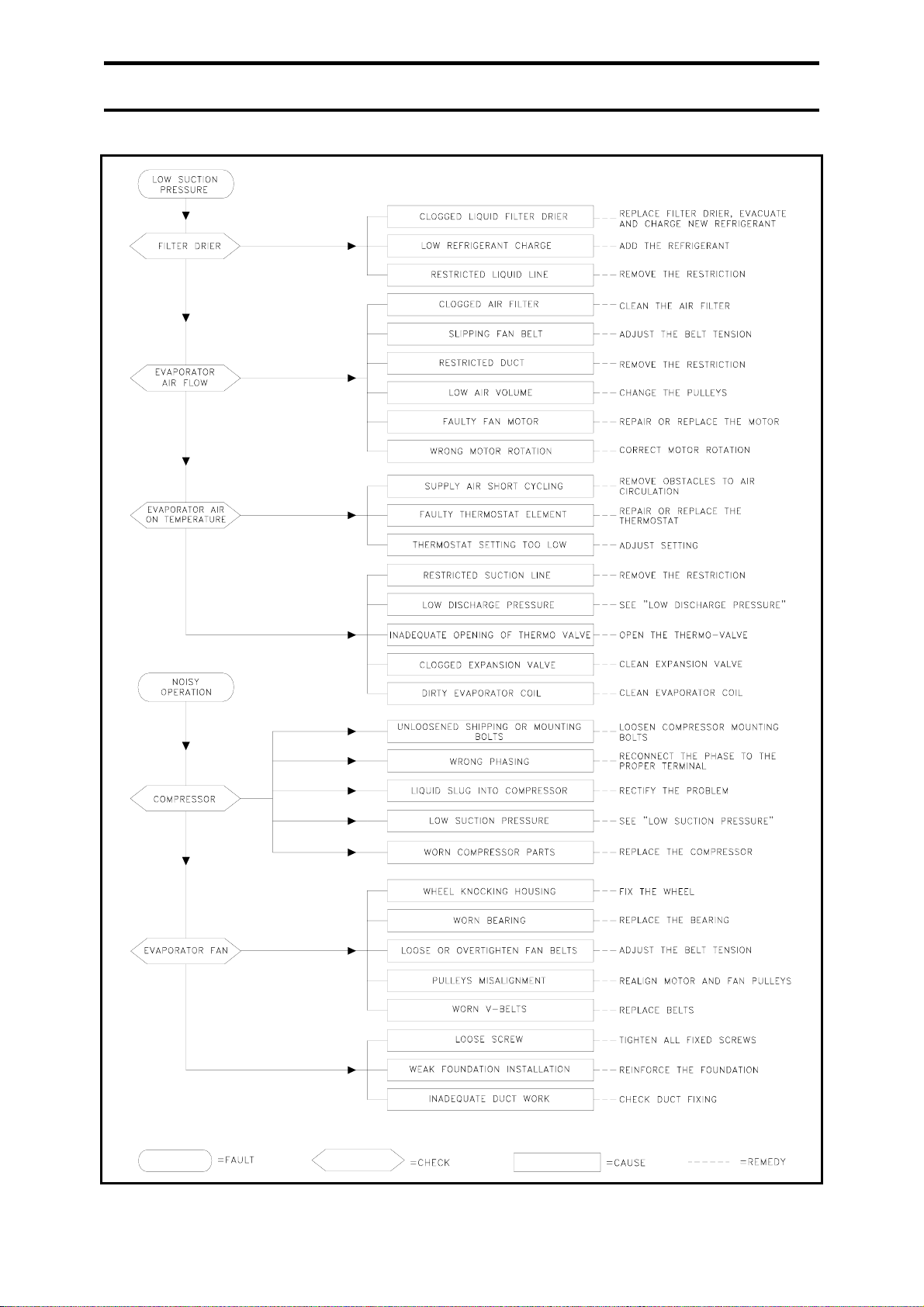
5.2 TROUBLE SHOOTING CHART
26
Page 27
5.0 MAINTENANCE
27
Page 28
5.0 MAINTENANCE
28
Page 29
5.0 MAINTENANCE
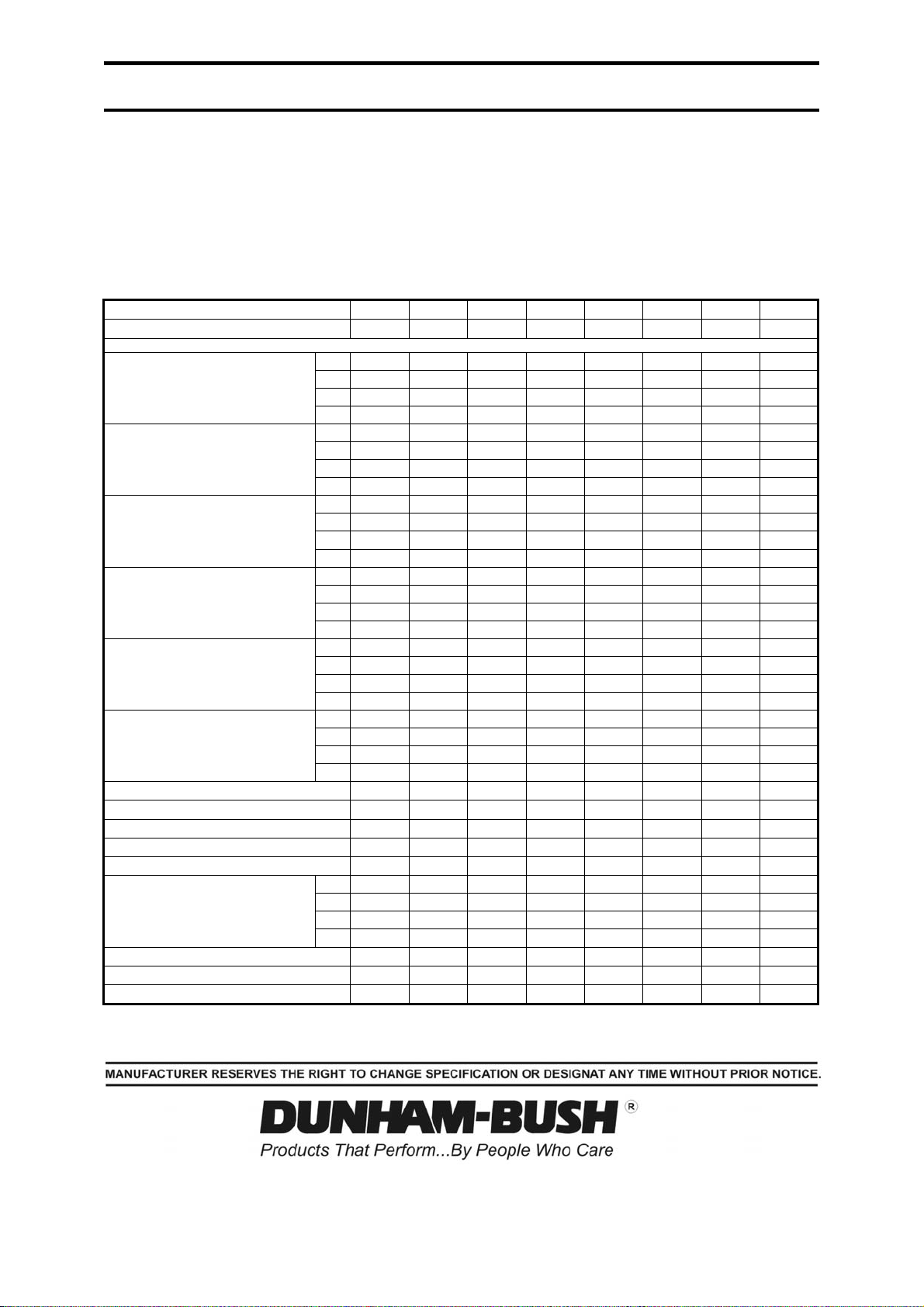
5.3 SAMPLE LOG SHEET SHEET NO..............................
DUNHAM-BUSH AIR COOLED SPLIT UNIT
UNIT MODEL NO. ........................................................UNIT NO..................................... VOLTS:.........................Hz.....................
UNIT SERIAL NO. ....................................................................................................................
START UP : DATE ..........................................TIME...................................................
DATE
TIME
COMP. NO.
1.
SUCTION PRESSURE
SUCTION TEMPERATURE
DISCHARGE PRESSURE
DISCHARGE TEMPERATURE
DISCHARGE SUPERHEAT
(DISC. TEMP.-SAT. DISCH.)
SUCTION SUPERHEAT
(SAT. SUCT .- SUC. TEMP)
RETURN AIR TEMPERATURE – DB/WB
SUPPLY AIR TEMPERATURE – DB/WB
AIR VOLUME
AMBIENT AIR TEMPERATURE
OFF CONDENSER AIR TEMPERATURE
COMPRESSOR AMPS
CONDENSER FAN AMPS
EVAPORATOR FAN AMPS
VOLTS
This log sheet is provided as a recommendation of the readings that should be taken on a periodic basis. The actual readings taken and the
frequency will depend upon the units application, hours of use, etc. This type of information can prove very useful in preventing and/ or solving
problems that might occur during the life of the unit.
2.
3.
4.
1.
2.
3.
4.
1.
2.
3.
4.
1.
2.
3.
4.
1.
2.
3.
4.
1.
2.
3.
4.
1.
2.
3.
4.
Lot 5755-6, Kidamai Industrial Park, Bukit Angkat, 43000 Kajang, Selangor Darul Ehsan, Malaysia
29
 Loading...