

Page 1
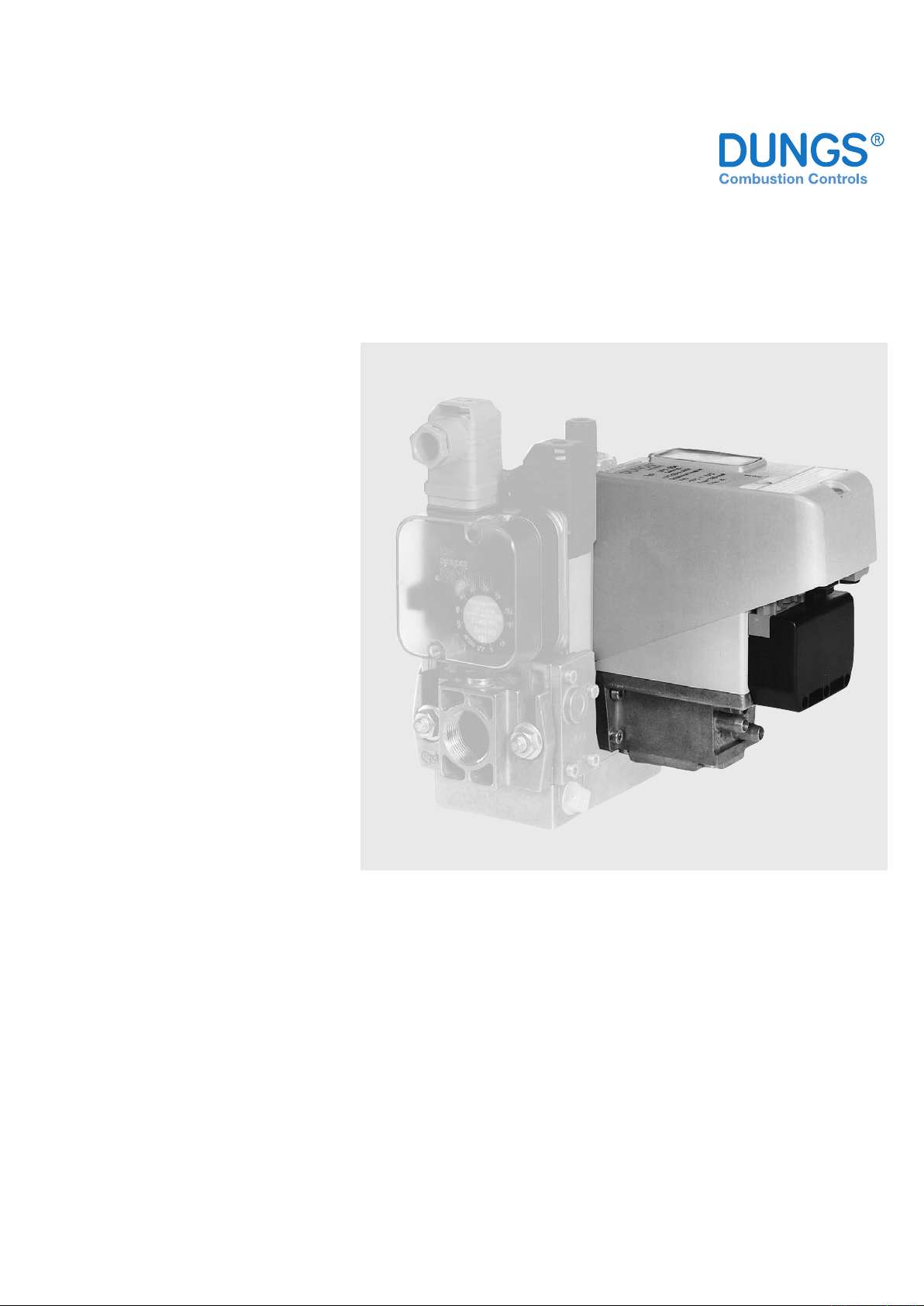
Valve testing system
VPS 508
for multiple actuators
8.13
1 … 12
Printed in Germany • Edition 02.10 • Nr. 255 265
Technical description
The VPS 508 is the valve proving system
for DUNGS multiple actuators. The valve
proving system complies with EN 1643:
- Equipment operates independent of
residual pressure in the range of the
permissible operating range.
- Test volume ≤ 8 l
- Setting work not necessary on site
- Short test period: min. 10 s, max. 34 s
- Tightness or leaks are displayed by an
LED
- External fault display possible for series
04 and S05
- Suitable for TRD systems
-
Electrical connection possible by plug connection S03. No rewiring is required for contact
allocation as per DIN 4791.
- S04 and S05: electrical connection at
screw terminals via PG 13.5 cable entry
Application
Valve proving system for DUNGS single
valves, DMV double solenoid valve and
GasMultiBloc MB.
The VPS 508 can also be used for monitoring
the DUNGS solenoid valves up to DN 100,
with and without bypass connection.
24 VDC design for gas motors.
Suitable for gases of gas families 1, 2, 3
and other neutral gaseous media.
Approvals
EC type test approval as per EC Gas Appliance Directive:
VPS 508… CE-0085 AP 0168
EC type test approval as per EC Pressure
Equipment Directive:
VPS 508… CE0036
Approvals in other important gas consuming countries.
Page 2

2 … 12
VPS 508 Valve proving system for automatic shuto valves as per EN 161, Class A and Class B
The VPS 508 may be used with any other valve whose tightness in counter-ow direction
excludes by construction a leakage in ow direction.
The VPS 508 is suitable for all DUNGS valves according to EN 161 Classes A and B.
Specications
Operating pressure
Test volume
Pressure increase by motor pump
Nominal voltage, Frequency
Rating requirement
Prefuse (provided by customer)
Fuse installed in housing cover,
replaceable
Switching current
Degree of protection
Ambient temperature
max. 500 mbar (50 kPa)
≥ 1.5 l
≤ 8.0 l
≈ 20 mbar
refer to type overview page 11
During pumping time approx. 60 VA, in operation 17 VA
10 A quick-acting or 6.3 A slow-acting fuse
Microfuse 6.3 slow-blow L 250 V; IEC-127-2/III (DIN 41 662)
Operating output VPS 508 S03, S04, S05: max. 4 A
Refer to motor startup current!
Interference output VPS 508 S04, S05: max.1A
VPS 508 S03: IP 40
VPS 508 S04, S05: IP 54
50 Hz 230 VAC -15 °C to +70 °C
others: -15 °C to +60 °C
Release time
Sensitivity limit
Switch-on duration of control
Max. number of test cycles
Installation position
Media
Approx. 10 - 34 s, depending on test volume and input pressure
max. 50 l/h
At inlet pressures of < 50 mbar, limit pressure rates well below 50 l of air per
hour occur due to the mode of operation. This allows for applications involving
low inlet pressures.
100 % ED
10/h. Wait for at least 2 minutes after carrying out more than 3 consecutive
test cycles.
vertical, horizontal, not upside down
Gas families 1, 2, 3, sewage gas, landll gas and biogas (dry, H2S < 0.1 % by
volume) and other gaseous media
Not for gases having a butane content of > 60 %
Page 3
3 … 12
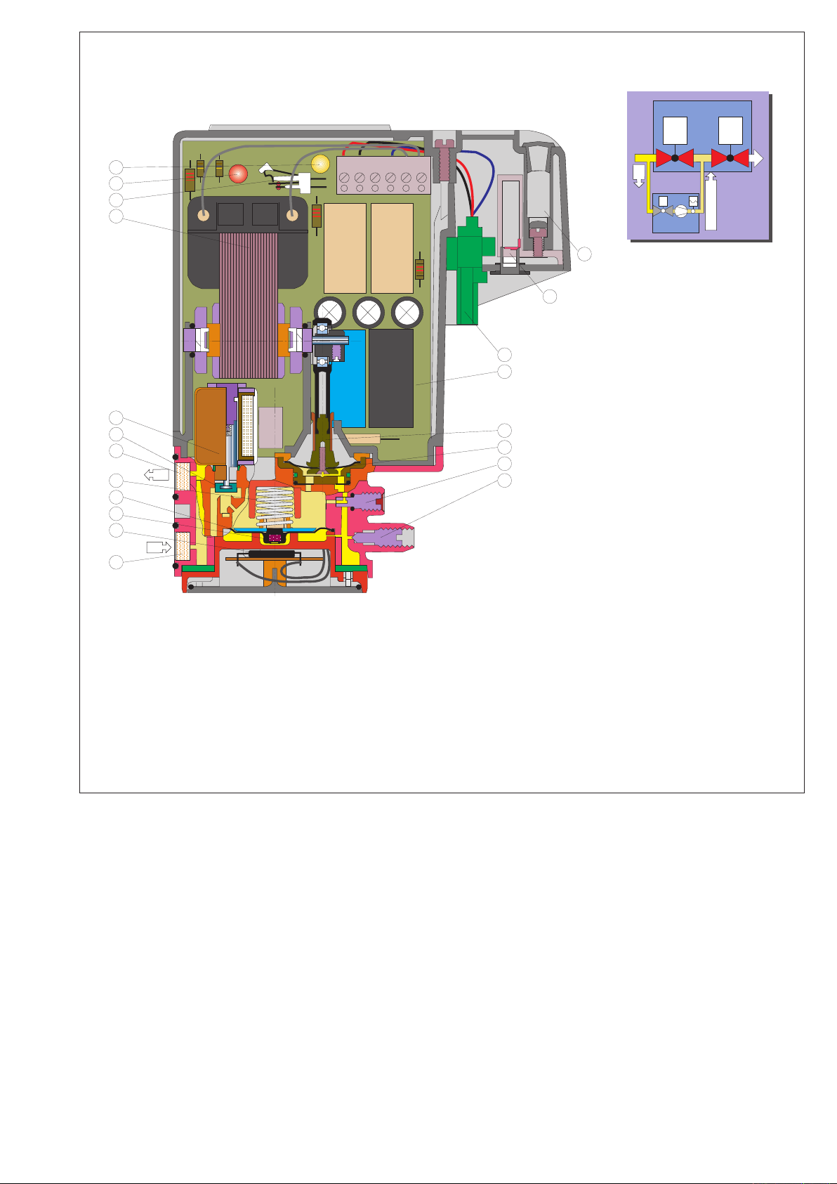
VPS 508 sectional diagram
V1 V2
1
7
8
VPS 508
DMV… Series
p
1
p
1
+
20 mbar
V2
4 3 2 1 2 1
p
2
p
1
16
15
14
13
12
6
5
4
3
2
1
7
10
11
8
9
17
5
18
19
1 Hall switch
2 Solenoid
3 Pressure switch diaphragms
4 Compression spring
5 Filter
6 Solenoid valve anchor
7 Solenoid valve coil
8 Pressure pump
9 Unlock switch
10 Fault lamp
11 Operating lamp
12 Test nipple
13 Volume restrictor
14 Pump diaphragm
15 Pump linkage
16 PCB
17 Plug connection
18 Equipment fuse
19 Spare fuse
Page 4
4 … 12
Functional description
V1
p = 500 mbar
max.
V2
VPS 508
p
2
p
a
p
1
p
e
p
2
p
a
p
1
p
e
DMV-D(LE)
A
A Program module
Instrument gland
Connection
V1
V2
VPS 508
p2
pa
p1
pe
p2
pa
p1
pe
Program
modul
p
e
p + 20 mbar
e
V1
V2
VPS 508
p
2
p
a
p
1
p
e
p
2
p
a
p
1
p
e
Program
modul
p
e
V1
V2
VPS 508
p
2
p
a
p
1
p
e
p
2
p
a
p
1
p
e
Program
modul
p
e
p + 20 mbar
e
V1
V2
VPS 508
p
2
p
a
p
1
p
e
p
2
p
a
p
1
p
e
Program
modul
p
e
V1
V2
VPS 508
p
2
p
a
p
1
p
e
p
2
p
a
p
1
p
e
Program
modul
p
e
V1
V2
VPS 508
p
2
p
a
p
1
p
e
p
2
p
a
p
1
p
e
Program
modul
p
e
p
e
p
e
2 3456 7 81
4
2
6
8
10
12
14
16
18
20
22
24
26
28
30
32
34
p
1
/p
e
= 100 mbar
p
1
/p
e
=
20 mbar
p
1
/p
e
= 200 mbar
p
1
/p
e
= 300 mbar
p
1
/p
e
= 500 mbar
tF [s]
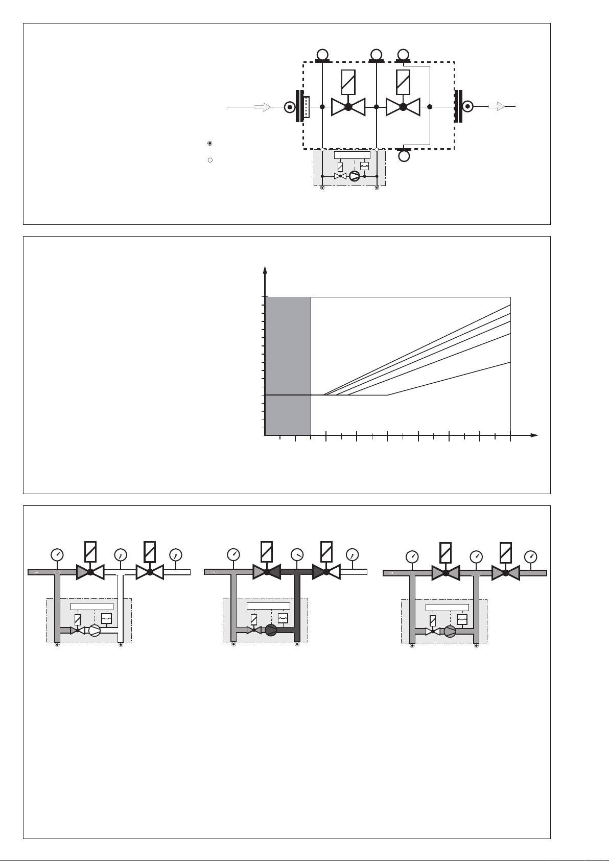
The VPS 508 operates depending on
pressure build-up.
The program module starts to function
when heat is requested.
Test is performed depending on the
burner functional procedure:
Check prior to burner start or
Check during pre-purge period or
Check after burner shut-down
Function principle
Release period t
F
Period which a VPS requires to perform a complete operation procedure.
The release period of the VPS 508
depends on test volume and input
pressure:
tF max. ≈ 34 s
Test period t
test
Pumping time of motor pump.
Test volume V
Test
Volume between V1 output-side and
V2 input-side and the intermediate
tube pieces.
V
test min. / VPS 508
V
test max. / VPS 508
= 1,5 l
= 8 l
Program sequence
Release period
Field of application
Test volume
V
[l]
prüf
Idle state: Valves 1 and 2 are closed.
Pressure build-up: The internal mo-
tor pump increases the gas pressure
in the test section by approx. 20 mbar
compared to the input-side pressure
applied to valve V1.
During the test period, the installed
dierential pressure switch monitors
the test section for leakage. If the test
pressure is attained, the motor pump
is switched o (end of test period). The
release time (10-34 s) depends on the
Idle state
test volume (max. 8.0 l) and input pressure (max. 500 mbar). If the test section
is tight, the contact is released to the
automatic burner control after max. 34
s - the yellow signal lamp lights up.
If the test section is leaky or if the pressure increase by + 20 mbar is not attained
during the test period (max. 34 s), the
VPS 508 switches to fault. The red signal
lamp lights as long as the contact release
by the regulator or thermostat is present
(heat requirement).
Pressure
build-up
Operation
If there is a short power failure during
the test or burner operation, the test
is started again automatically.
If the pumping time < approx. 10s,
the pressure dierence between the
testing system and the inlet pressure is
balanced after pumping is nished.
Operation: The internal valve of the
VPS 508 is closed.
Page 5
5 … 12
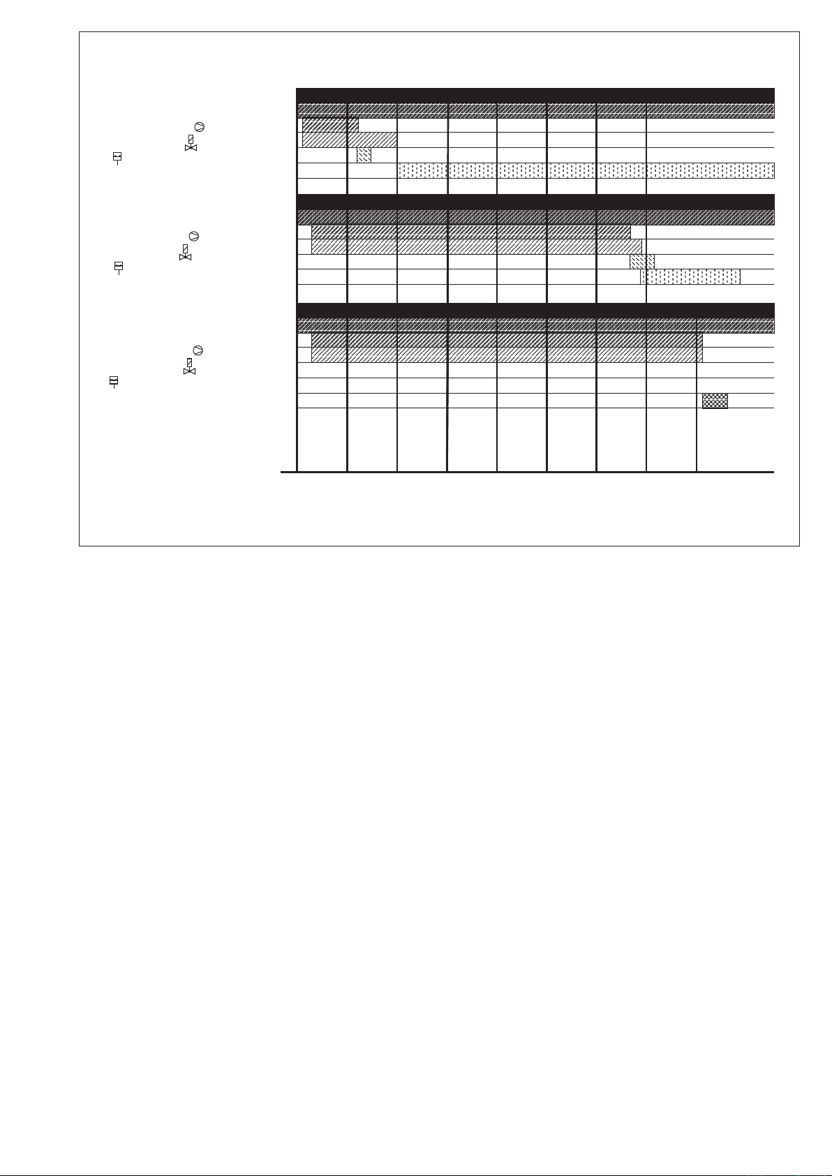
Program owchart
Regulator
Pump motor
Solenoid valve
Differential pressure switch
Release signal
Regulator
Pump motor
Solenoid valve
Differential pressure switch
Release signal
0 5 10 15 20 25 [s]30
VPS 508 "TIGHT" V
Prüf
= 2,0 l
VPS 508 "TIGHT" V
Prüf
= 8,0 l
VPS 508 "LEAKY"
35
40
Regulator
Pump motor
Solenoid valve
Differential pressure switch
Release signal
Fault signal
t
test
Page 6
6 … 12
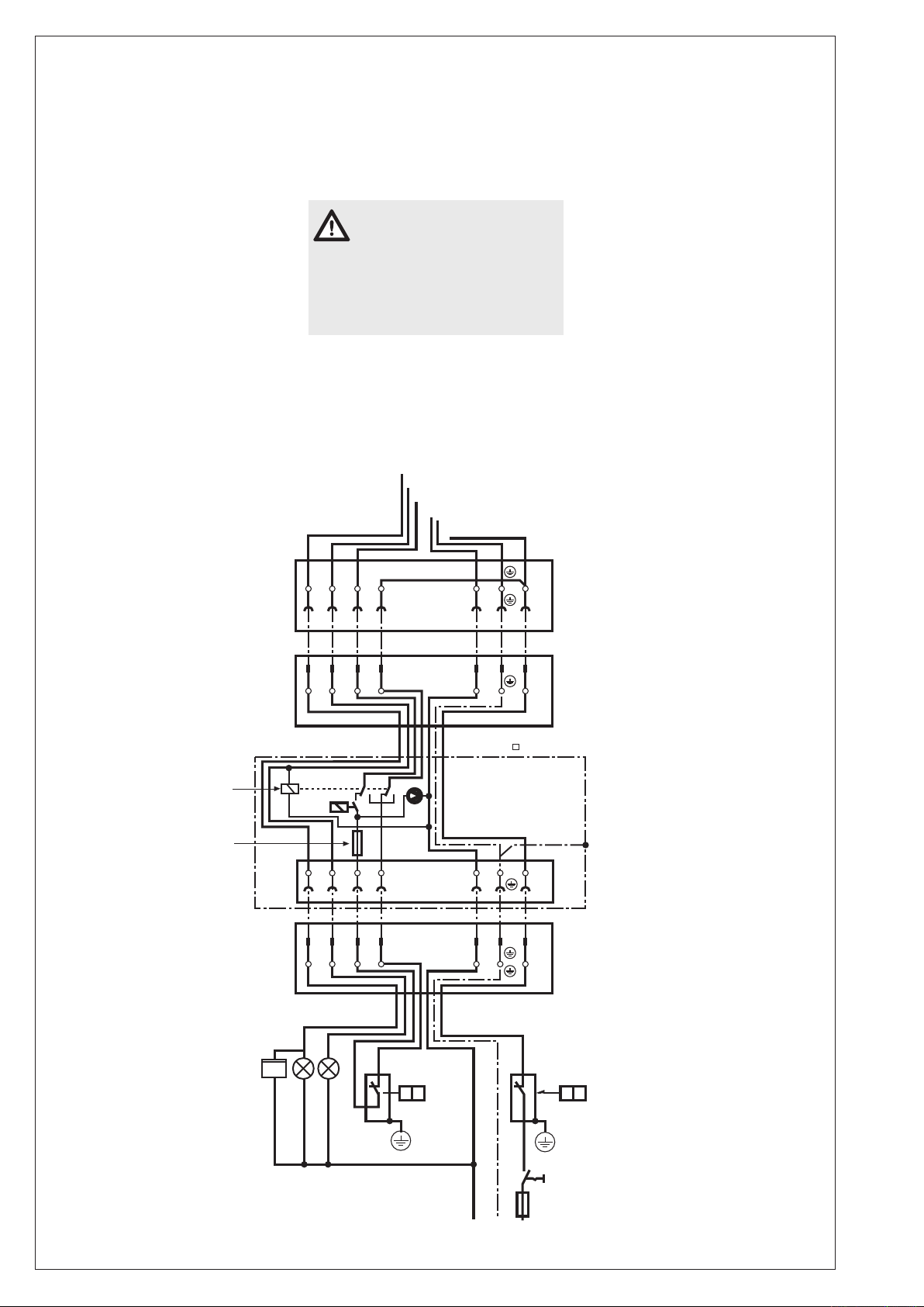
Electrical connection
N
Pe
L
6 5 4 2 1
3
B4 S3 T2 T1
N L
B4 S3 T2 T1 N L
6 5 4 3
2 1
B4 S3 T2 T1 N L
B4 S3 T2 T1 N L
6
5
4
3
2 1
6
5
4
3
2 1
h
P1 H2 H1
F3 F2
S1
F1
S P S P
VPS 508 S03
The VPS 508 S03 is connected in
series between the temperature regulator and the control box via a 7-pin
plug connector.
The pin assignment of the connector
between burner and boiler is specied
in DIN 4791. For contact assignment,
refer to wiring diagram.If the heat
generator is wired to DIN 4791,no
boiler or burner rewiring is required
for electrical connection.
Connect the burner connector to the
oating connector of the VPS 508
S03.
Connect the VPS 508 S03 connector
to the oating connector on the heat
generator.
If there is a fault signal at S3 (burner
fault), the regulator chain is bridged via
an additional relay in VPS 508 S03 on
the burner side. At the same time, the
operating voltage of VPS 508 S03 is
interrupted. After eliminating the burner
fault, the valve testing system can be
started again.
Only connect the incoming
fault signal from the igniter
of the burner control to port S3.
If this is not observed, damage
or injury may result. Therefore,
please keep to the instructions.
Solenoid valve
Burner operation
Fault
Regulator
F1 Fuse
F2 Sensor or limiter
F3 Regulator
H1 Fault signal
H2 Operation signal
P1 Operating hours meter
stage 1
S1 Switch
X1B Connector,
female
X1S Connector,
male
Operation
exchangeable fuse:
T 6,3 L 250 V
IEC 127-2/III
(DIN 41662)
D5 x 20
Burner female
connector
(X 1B)
Male connector
(cable to cable)
VPS 508
(X 1S)
Control line
7 x 1
VPS 508
S03
internal
Female connector
(xed)
VPS 508
(X 1B)
Male connector
of heat generator
(X 1S)
Page 7
7 … 12
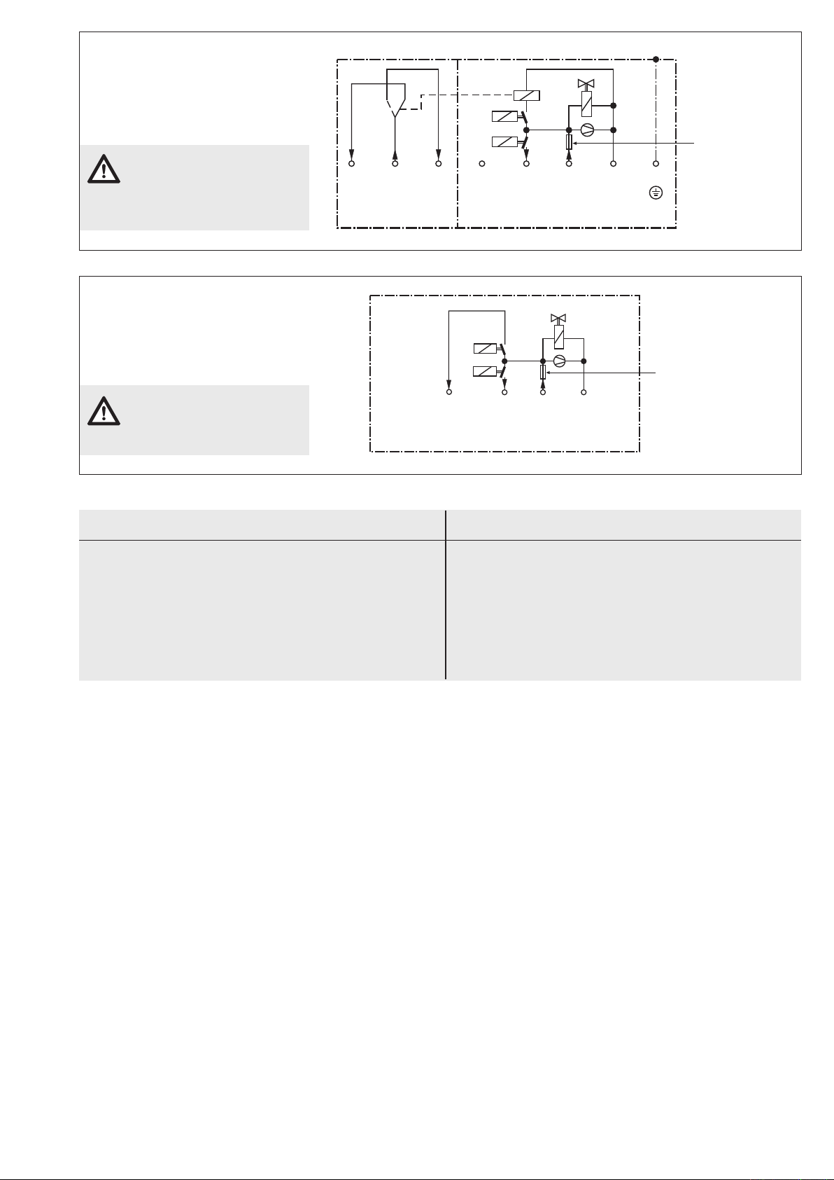
Electrical connection
VPS 508
series 05
internal
B +–
Operating voltage
= (DC) 24 V
Release
signal
tight
leaky
V3
P
S
Falut
signal
I
max./maxi.
:
B : 4A
S : 1A
exchangeable fuse:
6.3 slow-blow
L 250 V
as per
IEC 127-2/III
(DIN 41662) D5 x 20
NC COM NO B L1 N
Floating fault signal
(control room signal)
Operating voltage 230 V AC 50 Hz
}
Release
signal
Operating
voltage
Zero
conductor
Groung
tight
leaky
V3
P
exchangeable fuse:
6.3 slow-blow
L 250 V
as per
IEC 127-2/III
(DIN 41662) D5 x 20
VPS 508
S04
internal
VPS 508 S04
PG 13.5 cable duct and connection
to screw terminals below cover in
housing (see Dimensions VPS 508
S04, S05).
Floating control room signal
may only be used for signal-
ling, never for burner release.
Electrical connection
VPS 508 S05
PG 13.5 cable duct and connection
to screw terminals below cover in
housing (see Dimensions VPS 508
S04, S06).
Operating voltage range
20 V - 30 V DC. Refer to mo-
tor startup current!
Test volume of DUNGS multiple actuators DMV-..., MBC-...
Type
DMV-D(LE) 5080/11
DMV-D(LE) 5100/11
DMV-D(LE) 5125/11
DMV-D(LE) 5065/12
DMV-D(LE) 5080/12
DMV-D(LE) 5100/12
DMV-D(LE) 5125/12
Rp/DN
DN 80
DN 100
DN 125
DN 65
DN 80
DN 100
DN 125
Test volume [l]
1,47 l
2,28 l
3,56 l
1,47 l
2,28 l
3,55 l
6,00 l
Type
MBC 1900
MBC 3100
MBC 5000
MBC 7000
Rp/DN
DN 65
DN 80
DN 100
DN 125
Test volume [l]
1,47 l
2,28 l
3,55 l
6,00 l
Page 8
8 … 12
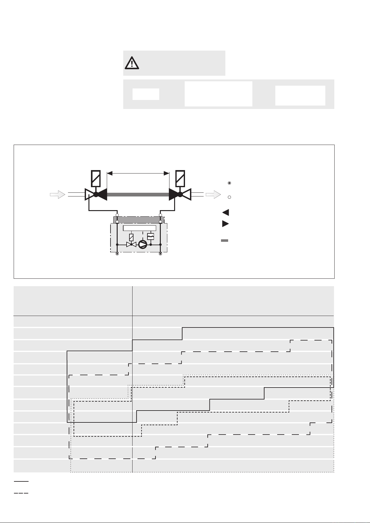
Use of VPS 508 at DUNGS single
V1 V2
L [m]
1 2
3
VPS 508
p
2
p
a
p
1
p
e
Adapter Nr. 222 740
Instrument gland
Connection
Volume V1
Volume V2
Volume
Intermediate pipe part V1 <−> V2
3
p
2
p
a
p
1
p
e
1
2
valves.
Determining the test volume.
When mounting the VPS 508 on single
valves DN 40-DN 100, the adapter set
is required, Ordering No. 222 740.
Determining the test volume V
test
1. Determine the output volume of V1
(refer to table).
2. Determine the input volume of V2
(refer to table).
3. Determine the volume of the intermediate pipe part 3 (refer to
table).
4. V
=
test
Volumen
Volumen
Volumen
+
valve 1
intermediate pipe part
valve 2
The max. test volume of 8 l
must not be exceeded.
V
Test
=
+
Valve volume
V1 outlet+
V2 inlet
+
Volume of
pipeline
Demetering test volume V
Rp / DN
Valve - Volume [l]
V1
+
outlet
V2
inlet
Rp DN Rp DN
Test
Test volume [l] = Volume V1
Pipeline lengths between individual valves L [m]
0,5 m
outlet
1,0 m
+ V2
inlet
+ Pipeline length
Rp DN
1,5 m
Rp DN
2,0 m
Rp DN
Rp 3/8
Rp 1/2
Rp 3/4 (DN 20)
Rp 1 (DN 25)
Rp 1 1/2 / DN 40
Rp 2 / DN 50
0,01 l
0,07 l
0,12 l
0,20 l
0,50 l
0,90 l
DN 65
DN 80
DN 100
DN 125
DN 150
DN 200
VPS 504 0,1 l ≤ V
------- VPS 508 0,4 l ≤ V
VDK 1,5 l ≤ V
········· DSLC 1,5 l ≤ V
0,06 l
0,17 l
0,27 l
0,45 l
0,70 l
1,20 l
1,10 l
1,90 l
2,0 l
3,8 l
6,5 l
12,0 l
17,5 l
46,0 l
≤ 4,0 l 1 l = 1 dm3 = 10-3 m
prüf
≤ 20,0 l
prüf
prüf
≤ 8,0 l
prüf
1,35 l
2,20 l
3,7 l
6,3 l
10,5 l
18,2 l
26,5 l
61,7 l
0,11 l
0,27 l
0,42 l
0,70 l
1,70 l
2,90 l
2,00 l
3,20 l
5,30 l
8,80 l
14,40 l
24,3 l
35,2 l
77,4 l
0,16 l
0,37 l
0,57 l
0,95 l
2,20 l
3,90 l
2,65 l
4,20 l
7,00 l
11,30 l
18,40 l
30,50 l
44,10 l
93,10 l
0,21 l
0,47 l
0,72 l
1,20 l
2,80 l
4,90 l
3,30 l
5,50 l
8,60 l
13,80 l
22,3 l
36,6 l
52,9 l
108,9 l
3
Page 9

9 … 12
Startup
1. Check test section for leaks after
assembly.
2. Start test by using temperature regulator and/or restart or by pressing the
reset button of VPS 508.
3. If the test section is tight
Depending on the length of the test
section and the residual pressure
applied, the pumping time is between
3 s and 34 s.
The release for the automatic burner
control is then given after approx. 10
s at the earliest (at small test volumes
and small input pressures) and after
approx. 34 s at the latest (at large test
volumes and large input pressures)
- the yellow signal lamp lights up.
If the test section is leaky
The test pressure is not attained.
The motor pump switches o, the red
fault lamp lights up. Switch-through to
the automatic burner control does not
take place.
Functional check
By opening a screw plug in test nipple
p2 (pa) during test period (pumping
time), leakage can be simulated and a
function check can take place.
Setting
The VPS 508 must not be adjusted
on site.
Assembly
Directly ange the VPS 508 laterally to
the DUNGS multiple actuators (mounting is possible on left-hand or right-hand
side) using two 10.5 x 2.25 O rings and
four M4 x 16 self-tapping screws.
If an exhaust gas valve is
installed in the boiler, it must
be open at the beginning of the
test.
In order to prevent functional
and leakage problems, we
recommend the use of solenoid
valves as per EN 161 Class A and
Class B.
Insufficiently shielded fre-
quency converters could
cause faults in the VPS due to
network disturbances.
Make provisions for sucient
electrical shielding.
Page 10
10 … 12
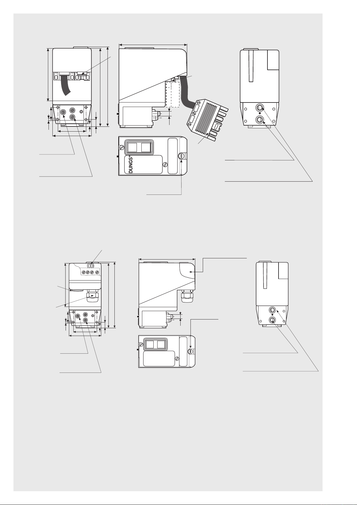
Dimensions [mm]
p
1
p
2
Ø 9
Betrieb
Fonctionamento
Funziamento
Run
Störung
Dérangement
Blocco
Lockout
126,5
Achtung, Warning, Attention, Attentione
Vor dem Öffnen ist das Gerät stromlos zu schalten
Before opening switch off power supply
Ouverture uniquement hors tension
Prima di apire l'aparecchio togliere la corrente
Typ: VPS 508
S04
pa
pe
100
22
4,3
72
53,7
5
13
147
150
5 6 7 8
p
1
p
2
Ø 9
Betrieb
Fonctionamento
Funziamento
Run
Störung
Dérangement
Blocco
Lockout
Typ: VPS 508
Serie 03
126,5
pa
pe
100
22
4,3
72
53,7
5
13
147
150
Sicherung eingebaut, auswechselbar
Fuse built into housing, exchangeable
Fusibile integré dans la couvercle du boîtier
interchangeable
Typ/Type/Type/Tipo T 6,3 L 250 V
Betriebsanleitung beachten!
Please comply with the operating instructions!
Suivre les instructions de la notice d'utilisation!
Seguire le istruzioni!
VPS 508 S03
Female connection X1B
as per DIN 4791
pe
test nipple
pa
test nipple
Dimensions [mm]
VPS 508 S04, S05
Additionally, PG 11
cable duct possibile
Standard:
cable duct
PG 13,5
Fuse
Spare fuses
Connector X1S
as per DIN 4791
Cover, electrical
connection
Spar fuse
Suction connection
(gas input)
Pressure connection
(to test section)
pe
test nipple
pa
test nipple
Suction connection
(gas input)
Pressure connection
(to test section)
Page 11

11 … 12
VPS 508 type overview / accessories / order data
Version
VPS 508 Series …
Nominal voltage, Frequency
VPS 508 S03
7-pole plug connection Cable length: 1.50 m
Wiring as per DIN 4791
IP 40 degree of protection
VPS 508 S04
Connection to screw terminals
PG 13.5 cable duct
Additionally, PG 11 possible
Floating fault signal (control room signal)
IP 54 degree of protection
VPS 508 S05 (Gasmotors)
Accessories/spare parts
Adapter kit VPS 504 for solenoid valves
Adapter kit VPS / VDK for solenoid valves
Mounting kit (4 x M4 x 16,2, 2 x O-Ring, 2 x lter insert)
Appliance fuse link (5 pieces)
Spare parts set VPS lter
20-30
VDC
251 008
222 740
223 470
221 503
231 780
243 801
230 V
-15 %
240 V
+6 %
50 Hz
251 011
251 004
110 V
-15 %
+10 %
50 Hz
251 012
251 005
Page 12

Valve testing system VPS 508
for multiple actuators
We reserve the right to make any changes in the interest of technical progress.
Head Oces and Factory
Karl Dungs GmbH & Co. KG
Siemensstraße 6-10
D-73660 Urbach, Germany
Telephone +49 (0)7181-804-0
Fax +49 (0)7181-804-166
Postal address
Karl Dungs GmbH & Co. KG
Postfach 12 29
D-73602 Schorndorf, Germany
e-mail [email protected]
Internet www.dungs.com
12 … 12
 Loading...