

Page 1
Manual
GB
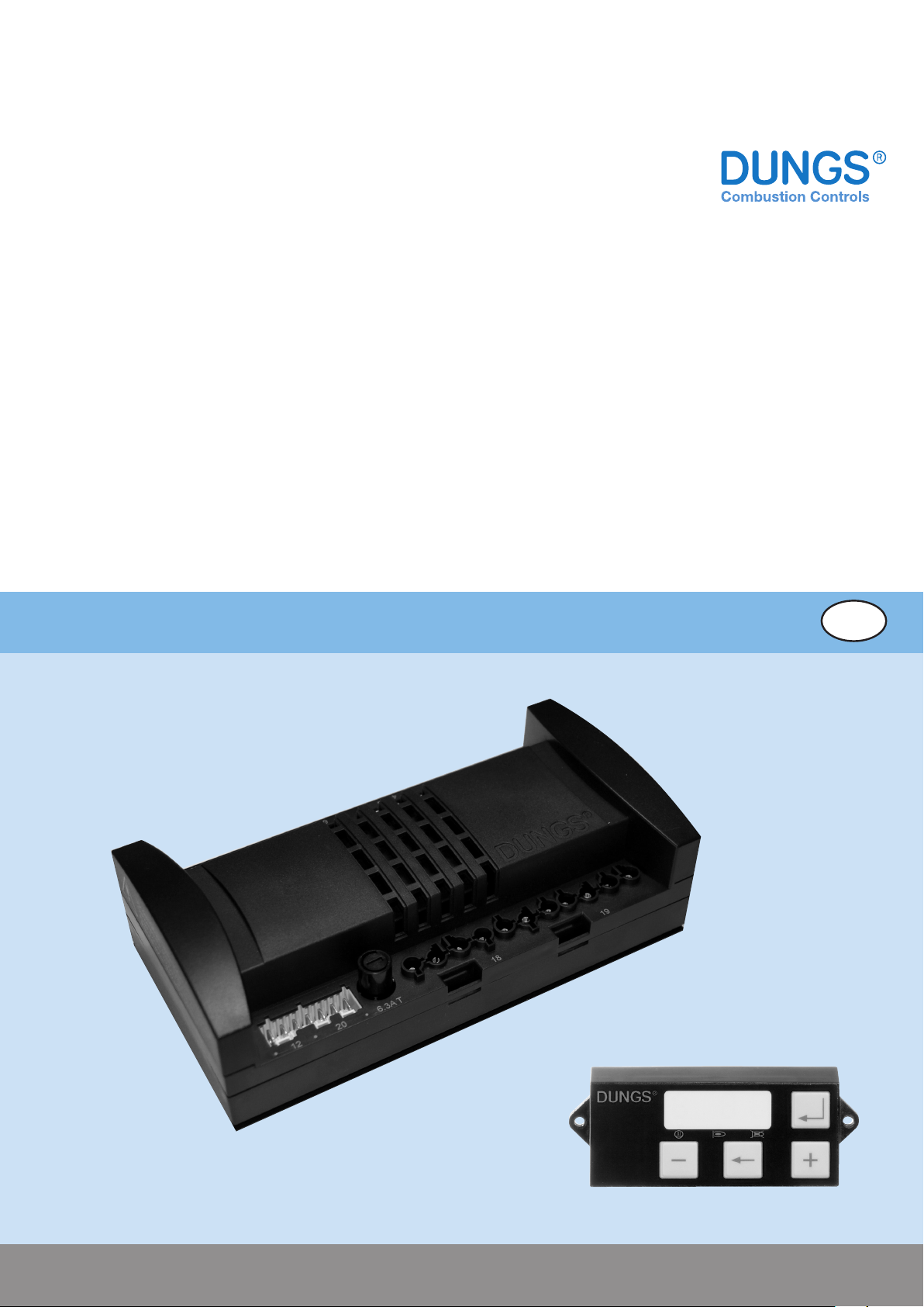
MPA 5111
Edition: 02.14
1 … 68
Printed in Germany • Edition 08.09 • Nr. 255 270
Nr. 254 722 - GB
Page 2

1 … 68
Printed in Germany • Edition 02.14 • Nr. 254 722
Page 3

Table of Contents
1 Short description ..................................................................................................................................................4
2 Accessories ...........................................................................................................................................................4
3 Classication according to EN298 ......................................................................................................................4
4 Approvals ...............................................................................................................................................................4
5. Technical data .......................................................................................................................................................5
5.1 General information ..............................................................................................................................................5
5.2 Outputs .................................................................................................................................................................5
5.3 Inputs ....................................................................................................................................................................6
5.4 Extension module .................................................................................................................................................6
6 Connection diagram .............................................................................................................................................7
7 Description of the behaviour ...............................................................................................................................9
7.1 Unlocking function ................................................................................................................................................9
7.2 Special operating modes .....................................................................................................................................9
7.2.1 Operation without valve testing system (VPS) ....................................................................................................9
7.2.2 Operation with valve testing system ...................................................................................................................9
7.2.3 Operation with reduced pre-aeration time ........................................................................................................14
7.2.4 Operation with ignition gas ame .....................................................................................................................14
7.3. Special setting options .......................................................................................................................................14
7.3.1 Dierent types of the air pressure detector monitoring .....................................................................................14
7.3.2 Dierent types of the temperature controller default or heat request ................................................................14
7.3.1 Dierent types of the modulation degree default ..............................................................................................14
7.3.4 Waiting program with open safety chain or lack of gas on the GDWVPS ..........................................................14
7.5 State description .................................................................................................................................................15
8 Parameters ...........................................................................................................................................................19
8.1 P1x General parameters .....................................................................................................................................19
8.2 P2x - Fan ............................................................................................................................................................23
8.3 P3x Stepped motor ............................................................................................................................................26
8.4 P4x - VPS ............................................................................................................................................................28
8.5 P5x - Additional valve ..........................................................................................................................................29
8.6 P6x - Startup .......................................................................................................................................................30
8.7 P7x - Operation ...................................................................................................................................................31
8.8 P8x - Switch-o ...................................................................................................................................................33
8.9 P9x - Waiting program .........................................................................................................................................34
8.10 Internal parameters ...........................................................................................................................................35
8.11 Parameter record and stick for continuous run ..................................................................................................36
9 Curve settings/modulation degree ....................................................................................................................37
9.1. Stick and VisionBox ............................................................................................................................................37
9.2 Denition of terms ...............................................................................................................................................38
9.2.1 Burner capacity ................................................................................................................................................38
9.2.2 Modulation degree ...........................................................................................................................................38
9.2.3 Curve point ......................................................................................................................................................38
9.2.4. Special point ...................................................................................................................................................38
10 Error overview ...................................................................................................................................................39
10.1 Errors from processor 2 ....................................................................................................................................39
10.2 Error from the basic system (0x01 to 0x3F) ................................................................................................39
10.3 Error from the extended functions (0x40 to 0x9F) .............................................................................................40
10.4 Error from the application (from 0xA0) ..............................................................................................................41
11 Display unit ....................................................................................................................................................... 43
11.1 Overview display modes ...................................................................................................................................43
11.2 Key assignment MPA 5111 and MPA 5112 .......................................................................................................44
11.4 Operational status display MPA5111 ................................................................................................................45
11.6 Error display ......................................................................................................................................................46
Printed in Germany • Edition 02.14 • Nr. 254 722
2 … 68
Page 4

11.7 Information display ............................................................................................................................................47
11.8 Service display ..................................................................................................................................................48
11.9 Parameterisation display ...................................................................................................................................49
11.9 Parameterisation display ...................................................................................................................................50
11.10 Reset display ..................................................................................................................................................51
11.11 Error memory display ......................................................................................................................................53
11.12 Password entry parameter record stick ...........................................................................................................54
12 VisionBox ...........................................................................................................................................................55
13 Flame detector...................................................................................................................................................56
14 Stepped motor ...................................................................................................................................................57
14.1 Overview of the possible stepped motor types ..................................................................................................57
14.2 Reference point "Standard" ...............................................................................................................................57
14.3 Reference point "Exchanged" ...........................................................................................................................57
14.4 Mathematical angle positions............................................................................................................................58
14.5 Wiring diagram SAD15Power supply ................................................................................................................59
14.6 Power supply of the stepped motors .................................................................................................................60
15 Time diagram ............................................................................................................................................... 62-63
Appendix
Appendix A Versions and variants
Appendix B Parameter overview
3 … 68
Printed in Germany • Edition 02.14 • Nr. 254 722
Page 5

1 Short description
Microprocessor-controlled burner control system for intermittent operation or
continuous operation for controlling and
monitoring pneumatically modulating
fan-assisted gas burners with speedregulated or controlled fan and power
controller input.
Extension modules for:
• analogue inputs/outputs
• Stepped motor
• Continuous operation
2 Accessories
• MPA-Extension module / Parameter record-Stick
• Flame monitoring system
• Display unit
• VisionBox
3 Classication according to
EN298
According to the programming, the
following classications are possible:
• FBLLBB
• FBCLBB
• FMLLBB
• FMCLBB
4 Approvals
EC-type examination certicate
according to EC-gas appliances
directive
CE number: CE 0085 BT 0056
Printed in Germany • Edition 02.14 • Nr. 254 722
4 … 68
Page 6
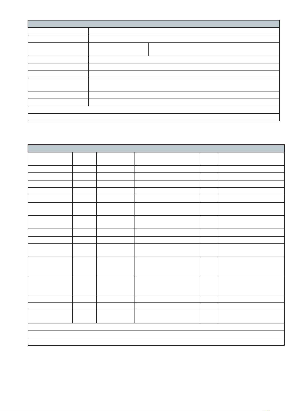
5. Technical data
5.1 General information
Rated voltage 230 V AC -15 % ... +10 %
Frequency 50 ... 60 Hz
Fuse MPA 5111 6.3 A slow-blow fuse or 10 A fast-blow fuse, integrated,
exchangeable
Type of protection IP 20
Ambient temperature 0 °C +60 °C
Humidity DIN 60730-1, no dewing admissible
Electrical connection Correct phase sequence and protective earth conductor according to the wiring dia-
gram
Mounting position as desired
Dimensions approx. 200 x 105 x 115 mm
The admissible cable length to the display is max. 3 m
The admissible cable length to the stepped motor is max. 3 m
5.2 Outputs
Designation Safety-
related
Type of output Electrical data MPA
5111
Extension Module
Additional valve Y1 ● Relay contact 230 V AC / 2 A (∑ < 5 A) ●
Valve Y2 ● Relay contact 230 V AC / 2 A (∑ < 5 A) ●
Valve Y3 ● Relay contact 230 V AC / 2 A (∑ < 5 A) ●
Spark generator ● Relay contact 230 V AC / 3 A (∑ < 5 A) ●
Fan Relay contact 230 V AC / 4 A ●
PWM 1 (for ex.
PWM 24-31 V DC / 4 kHz ●
fan)
Fused mains
Main volltage 230 V AC / 4 A _ ●
power supply
Operation display Internally via V2 230 V AC / 1 A (∑ < 5 A) ●
Fault output Relay contact 230 V AC / 1 A ●
Supply
ame detector
PWM 2 (e.g. 0...10
V)
Internally via
fan
for example
analogue
230 V AC / 0.1 A ●
for example 0...10 V _ ●
output
PWM 3 (e.g. 4...20
mA)
for example
analogue
for example 4...20 mA _ ●
output
Stepped motor Plug ●
Display Plug ●
TWI communica-
Plug ●
tion
Cable length max. 10 m
The sum of the currents of all safety-related consumers must not exceed 5 A!
The sum of the currents of all consumers must not exceed 6.3 A (10 A)
5 … 68
Printed in Germany • Edition 02.14 • Nr. 254 722
Page 7
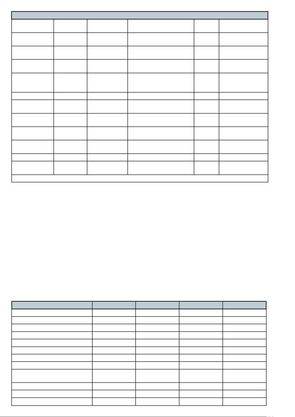
5.3 Inputs
Designation Safety-
related
Flame
● Ionisation Threshold value: approx.
detector
Air pressure
●
switch
Gas pressure
●
detector
Gas pressure
● Switching con-
detector VPS
Safety chain ●
Temperature
controller
Power controller
+/-
Fan
speed
Exchangeable
backup fuse
Remote unlocking
Analogue set-
point
Type of input Electrical data MPA
Extension Module
5111
●
1.2 µA
Switching contact
24V DC / 10 mA ●
(potential-free)
Switching contact
24V DC / 10 mA ●
(potential-free)
24V DC / 10 mA ●
tact (potentialfree)
Switching contact
Switching contact
Switching contact
230V AC / max. 10 A ●
230V AC ●
230V AC ●
Hall sensor 24V DC ●
Fuse 6.3 A slow-blow or 10 A
●
fast-blow
Switching contact
230V AC ●
Plug ●
Cable length max. 10 m
5.4 Extension module
equipped with analogue inputs and
outputs (e.g. MPA-EM1/3):
Analogue outputs
0/2...10 V, load >= 2 kilo ohms
0/4...20 mA, load <= 500 kilo ohms
(Attention! The output must not connected to GND!)
Analogue input
0/2...10 V, Imax = 0.5 mA
or
0/4...20 mA, apparent ohmic resistance R <= 500 kilo ohms
The inputs and outputs are NOT
electrically isolated from the mains!
Integrated function MPA-EM1/1 MPA-EM1/2 MPA-EM1/3 MPA-EM1/4
Display ● ● ● ●
TWI ● ● ● ●
Parameter record-stick - ● ● ●
0...10 V input - - ● ●
0...10 V output - - ● ●
4....20 mA input - - ● -
4...20 mA output - - ● Stepped motor output ● ● ● ●
{component protection / encapsu-
● ● ● -
lated version}
Type of wiring diagram A A A A
P18: Operating mode PWM output 0 0 11 8
P27: Modication method Modulation 0,1 0,1 0,1,2,3 0,1, 2 , 3
Printed in Germany • Edition 02.14 • Nr. 254 722
6 … 68
Page 8
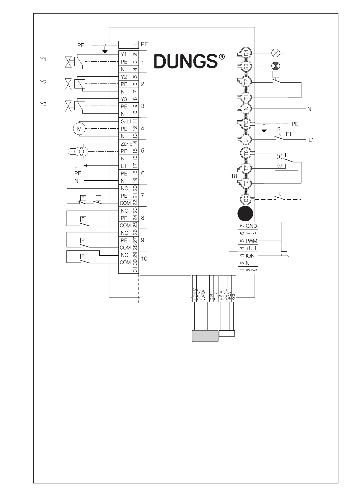
6 Connection diagram
Operation
Fault
υ
Fan motor
Spark generator
Safety
chain
GDW min.
GDW VPS
Air
pressure switch
MPA5111
Controller
chain
19
Mains
~(AC) 230 V
50/60 Hz
Power
controller
Remote
υ
Fuse
20
unlocking
230 V
Fan
Ionisation
12
Attention!
The designations Y1, Y2 and Y3
refer to the slots of the MPA.
Attention!
Output "operation" is internally connected to V2, i.e. it is also active in
the states such as valve check.
Attention!
F1 is only necessary if no internal
backup fuse is integrated!
variable
Display
Extension module
EMX/Y
TWI
7 … 68
Printed in Germany • Edition 02.14 • Nr. 254 722
Page 9
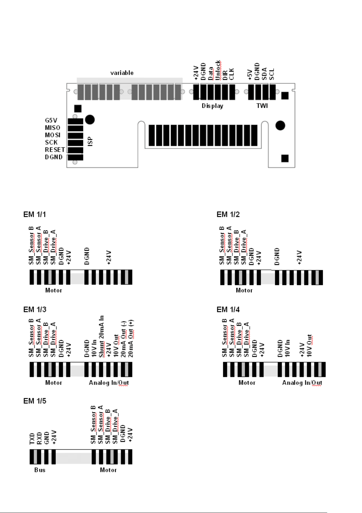
Wiring diagram for extension module
The extension modules EMX/Y are plug-in printed circuit boards.
For the conguration the EM1/1 is the minimum requirement.
Old extension modules have a slot for display connection and a slot for PC/laptop connection via VisionBox for
system conguration.
Additional connection options are provided in the "variable area".
The functions and pin assignments are dierent depending on the EM variant.
Printed in Germany • Edition 02.14 • Nr. 254 722
8 … 68
Page 10

9 … 68
7 Description of the behaviour
7.1 Unlocking function
If the MPS is locked (state 0), it can
be unlocked by pressing the unlock
key. In order to distinguish the function from potential EMC interfering
impulses, the key must be kept de-
pressed for at least 1/4 second.
The same applies for the 230 V unlocking.
According to DIN EN 14459 (annexe
J), the number of possible unlockings are limited to 5 in 15 minutes,
that means the automatic system
denies further unlockings if the MPA
has been unlocked more than 5 times
within a short time period. Only after a
waiting time during which the MPA is
provided with power, it is possible to
unlock the MPA again.
The waiting time is 15 minutes or 3
minutes for each unlocking
Extended unlocking
The described limitation to 5 unlockings in 15 minutes can be reset using
the "Extended unlocking". To do this,
the unlock key must be pressed for at
least 5 s (max.. 10 s) (after 5 s, the dis-
play begins to ash).
The "Extended unlocking" is active
in all operational states of the MPA,
that means that a safety cut-o with
restart of the MPA in operation can be
carried out via the "Extended unlock-
ing" also in the presence of a ame.
230 V unlocking input!
7.2 Access level
Write access to MPA is dened on different access levels.
Each parameter is assigned to a certain access level. In order to modify
a parameter, MPA must be at the assigned or higher level.
If the access level is not sucient to
modify a parameter, the VisionBox
reports it, or a message is output on
the MPA display prompting the user
to enter the valid password. At higher
levels, the users must press a key to
conrm that they are "on site". For this
purpose the display is ashing for 30 s
if a key is pressed; otherwise, the MPA
remains at the previous level.
To change the access level, the correct password must be entered in the
"VisionBox → Settings MPA → Access
level". The access level is automatically reset after 5 hours or after power
Printed in Germany • Edition 02.14 • Nr. 254 722
failure. Exception: If the automatic gas
burner performs a restart during these
5 hours, for example due to an error,
these 5 hours for the current access
level are counted again from the beginning.
NOTE: After completing conguration
of the automatic gas burner it is recommended to reset the access level
immediately manually (display) by
means of the shortcut - and ←, setting
"E1" (see chapter Display unit).
Level Designa-
tion
Key conrmation
required
1 Dungs yes
2 OEM Ex-
yes
pert
3 OEM yes
4 Service yes
5 Operator no
7.3 Parameter change
Parameter types:
1-bit parameter (U1) - setting 0 and 1
(displayed as ON/OFF), no limits
8-bit parameter (U8) - value setting
within variable limits
16-bit parameter (U16) - value setting
within variable limits.
A parameter can be modied on the
display (see Appendix BMA_display)
of MPA or via the VisionBox software
on a PC.
In order to change a parameter, the
access level assigned to the parameter must be set, see chapter Access
level.
The value must be within the variable
limits; a value outside these limits is not
possible or it is rejected by the MPA.
Experts can change the variable up-
per and lower limits, usually it requires
a higher access level than the level
assigned to the parameter value. The
variable limits may only be changed by
means of VisionBox, not on the MPA
display. The variable limits are restricted by means of xed limits. The variable limits cannot be changed outside
of these limits. These xed limits cannot be changed.
There are parameters which cannot be
changed during normal operation, see
Appendix Parameter table. To change
these parameters it is necessary to
switch to the state "Waiting for heat re-
quest".
The parameter stick (extension module) monitors selected parameters during start-up (see 8.11)
7.4 Special operating modes
7.4.1 Operation without valve check
system
If the valve check during start-up (P40)
and the valve check after a regular
switch-o (P41) are inactive, a simultaneously activated double gas valve
can also be used instead of two individual gas valves. This double valve
must be activated using the valve
output V2 of the MPA since V1 opens
before the safety time for the start-up
has elapsed!
Note: Even if P46 is "active", the input
GDWVPS is still monitored!
7.4.2 Operation with valve check
system
If the valve check is active during startup (P40), it will be carried out during
each start-up. The time required for
the valve check is not included in the
Adjustable pre-aeration time (P60
and P61) and, therefore, it can be reduced.
If the valve check after a regular
switch-o (P41) is active, it will be carried out after every regular switch-o.
Additionally, a valve check during
start-up is carried out if the valve check
after the last regular switch-o has not
been successful, if the automatic sys-
tem has been switched o by a safety
shutdown or if a power failure has oc-
curred since the last switch-o.
If the valve tightness test has been
completed successfully and P41 is inactive, the tightness test and the state
"Pre-aeration B" are skipped during
the next start-up (see section "Operation with reduced pre-aeration time").
Page 11

For a correct evaluation of the tests
carried out, the parameters P40 to
P46 must be correctly calculated and
set.
pe * VP * In (pe / (pe - pS1))
t
= ------------------------------- * 3600 s/h * S
test V1
p
* Q
atm
P
pe * VP * In (pe / pS2)
t
= ------------------------------- * 3600 s/h * S
test V2
t
P43
t
P45
= t
= t
p
test V1
test V2
* Q
atm
* 16/s
* 16/s
P
Formula to calculate the test
times for V1 and V2:
t
test V1
t
test V2
t
P43
t
P45
p
e
p
S1
[s] Test time for V1
[s] Test time for V2
[ ] to be entered in P43
[ ] to be entered in P45
[mbar] Gas inlet pressure
[mbar] Increasing switching pressure
(set pressure at the controller +15 %
+ switching dierence)
p
S2
[mbar] Falling switching pressure
(set pressure at the controller -15 %)
p
atm
[mbar] Atmospheric pressure = 1013
mbars
V
P
[dm3] Test volume between the valves to
be monitored
Q
P
[dm3/h] Admissible leakage rate according
to EN1643.
The leakage rate corresponds to
0.1 % of the burner's gas consumption at maximum burner load, but
at least 50 dm3/h. A limit value of
200 dm3/h is recommended by
DUNGS!
S [ ] Safety factor, DUNGS recom-
mends triple safety
Printed in Germany • Edition 02.14 • Nr. 254 722
10 … 68
Page 12

Example
A DMV-D(LE) 525/11 with 20 mbars
inlet pressure is used. In this application, the admissible leakage rate
according to EN1643 is3 / h. The gas
pressure detector is set to 10 mbars.
20 mbar * 0.44 dm3 * In (20 mbar / (20 mbar - 12.5 mbar))
t
= ------------------------------------------------------------------------ * 3600 s/h * 3 = 1.84 s
test V1
t
P43
1013 mbar * 50 dm3 / h
= 1.84 s * 16/s = 29.5
To be entered in P43: 30 or more
(corresponds to 1.88 s)
20 mbar * 0.44 dm3 * In (20 mbar / 8.5 mbar)
t
= ------------------------------------------------------------------------ * 3600 s/h * 3 = 1.61 s
test V2
1013 mbar * 50 dm3 / h
pe = 20mbars
VP = 0.44 dm3see Test volume table, page 12
QP = 50 dm3 / h (determined according to DIN EN 1643)
pS1 = 10mbars + 15 % + 1mbar switching dierence = 12.5 mbars
pS2 = 10mbars - 15 % = 8.5 mbars
S = 3 (recommendation DUNGS)
t
= 1.61 s * 16/s = 25.7
P45
To be entered in P45: 26 or more
(corresponds to 1.63 s)
Valve/valves leaking
1. Switch o system
2. Check valve V1 and/or V2 for leakage
3. If leaking, replace valve V1 and/or V2.
Attention! In case of interference suppression, always observe the
application- and country-specic requirements as well.
11 … 68
Printed in Germany • Edition 02.14 • Nr. 254 722
Page 13

Test volume of the DUNGS Multiple actuators MB-D ..., MB-ZR..., MB-VEF..., DMV-...., MBC....
Type Nominal diameter
Test volume
Rp / DN
DMV-D(LE) 503/11 Rp 3/8 0.03 l
DMV-D(LE) 507/11 Rp 3/4 0.10 l
DMV-D(LE) 512/11 Rp 1 1/4 0.24 l
DMV-D(LE) 520/11 Rp 2 0.24 l
DMV-D(LE) 525/11 Rp 2 0.44 l
DMV-D(LE) 5040/11 DN 40 0.38 l
DMV-D(LE) 5050/11 DN 50 0.39 l
DMV-D(LE) 5065/11 DN 65 0.69 l
DMV-D(LE) 5080/11 DN 80 1.47 l
DMV-D(LE) 5100/11 DN 100 2.28 l
DMV-D(LE) 5125/11 DN 125 3.56 l
DMV-1500-D Rp 2 0.44 l
DMV-...(DLE) –65 DN 65 1.47 l
DMV-...(DLE) –80 DN 80 2.28 l
DMV-...(DLE) –100 DN 100 3.55 l
MB-D(LE) 403 Rp 3/8 0.04 l
MB-D(LE) 405 Rp 1/2 0.11 l
MB-D(LE) 407 Rp 3/4 0.11 l
MB-D(LE) 410 Rp 1 0.33 l
MB-D(LE) 412 Rp 1 1/4 0.33 l
MB-D(LE) 415 Rp 1 1/2 0.24 l
MB-D(LE) 420 Rp 2 0.24 l
MB-ZRD(LE) 405 Rp 1/2 0.11 l
MB-ZRD(LE) 407 Rp 3/4 0.11 l
MB-ZRD(LE) 410 Rp 1 0.33 l
MB-ZRD(LE) 412 Rp 1 1/4 0.33 l
MB-ZRD(LE) 415 Rp 1 1/2 0.24 l
MB-ZRD(LE) 420 Rp 2 0.24 l
MB-VEF 407 Rp 3/4 0.11 l
MB-VEF 412 Rp 1 1/4 0.33 l
MB-VEF 415 Rp 1 1/2 0.24 l
MB-VEF 420 Rp 2 0.24 l
MB-VEF 425 Rp 2 0.44 l
MBC 300 Rp 3/4 0.05 l
MBC 700 Rp 1 1/4 0.61 l
MBC 1200 Rp 2 2.05 l
MBC 1900 DN 65 1.47 l
MBC 3100 DN 80 2.28 l
MBC 5000 DN100 3.55 l
Printed in Germany • Edition 02.14 • Nr. 254 722
12 … 68
Page 14
Determination of the test volumes for DUNGS Single solenoid valves.../5
Nominal diam-
Test volumes = volume V1
output side
+ V2
input side
+ pipeline
eter
Rp / DN
direct 0.5 m 1.0 m 1.5 m 2.0 m
Rp DN Rp DN Rp DN Rp DN Rp DN
Rp 3/8 0.01 l 0.06 l 0.11 l 0.16 l 0.21 l
Rp 1/2 0.07 l 0.17 l 0.27 l 0.37 l 0.47 l
Rp 3/4 (DN 20) 0.12 l 0.27 l 0.42 l 0.57 l 0.72 l
Rp 1 (DN 25) 0.20 l 0.45 l 0.70 l 0.95 l 1.20 l
Rp 1 1/2 / DN 40 0.50 l 0.7 l 1.10 l 1.35 l 1.70 l 2.0 l 2.20 l 2.65 l 2.80 l 3.3 l
Rp 2 / DN 50 0.90 l 1.2 l 1.90 l 2.2 l 2.90 l 3.2 l 3.90 l 4.2 l 4.90 l 5.5 l
DN 65 2.0 l 3.7 l 5.3 l 7. 0 l 8.6 l
DN 80 3.8 l 6.3 l 8.8 l 11. 3 l 13.8 l
DN 100 6.5 l 10.5 l 14.4 l 18.4 l 22.3 l
DN 125 12.0 l 18.2 l 24.3 l 30.5 l 36.6 l
DN 150 17. 5 l 26.5 l 35.2 l 4 4.1 l 52.9 l
DN 200 46.0 l 61.7 l 77.4 l 93.1 l 108.9 l
Typical values for the leakage rate
DN Test volume [litres]
direct / 2 m
~ Burner capacity [kWh adm. leakage rate
[dm3 / h]
0.1 % of the burner
capacity or 50 dm3 / h
5 mbars 30 mbars
20 0.12 / 0.72 110 240 50
25 0.20 / 1.20 170 370 50
40 0.50 / 3.30 310 710 50 -71
50 0.90 / 5.20 500 1100 50 -110
65 2.00 / 8.60 910 2000 91-200
80 3.80 / 13.8 1250 2900 125-290
100 6.50 / 20.0 2050 4600 205-460
125 12.5 / 20.0 3500 7700 350-770
13 … 68
Printed in Germany • Edition 02.14 • Nr. 254 722
Page 15
7.4.3 Operation with reduced preaeration time
Under specic circumstances, the
MPA can be started with a reduced
pre-aeration time. For doing this, the
valve tightness test after a regular
switch-o (P41) must have been successful.
Settings for the operation without reduced pre-aeration:
a) Pre-aeration time A (P60): desired
duration of the pre-aeration
b) Pre-aeration time B (P61): 0 (= is
never carried out)
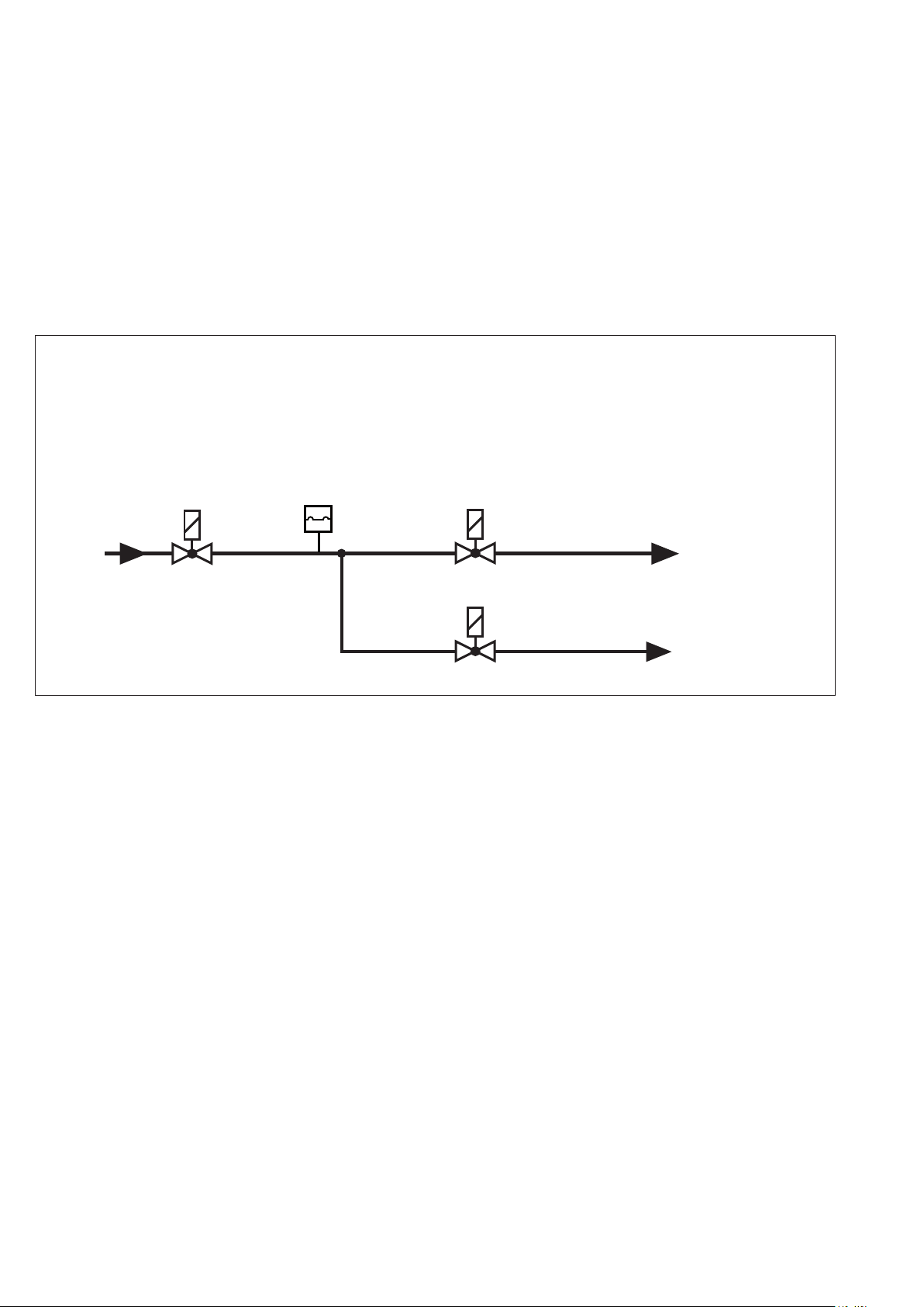
7.4.4 Operation with ignition gas
ame
Basically, the MPA can be used
for the operation with ignition gas
ame.
Attention!
There is only one input for ame
monitoring (ionisation).
Setting for the operation with reduced
pre-aeration time:
a) Pre-aeration time A (P60): 0 or
pre-aeration time that is always
required
b) Pre-aeration time B (P61): desired
duration of pre-aeration if the
valve tightness test was NOT nished successfully. This duration
is ignored if the valve tightness
test was successful after the last
regular switch-o (duration 0)!
additional
V Zusatz
V1
The common pre-valve must be connected to V1. The ignition gas valve
is connected to the output V2 of the
MPA and the main gas ame to the
freely congurable additional valve
output.
7.5 Special setting options
7.5.1 Dierent types of the air
pressure detector monitoring
See section 8 "Parameter description" - P14.
GDW
VPS
V2
Attention!
The additional valve output must be
congured according to the desired
behaviour, that means that the moment for opening (P50 and P52) and
closing (P51 and P53) must be de-
ned via the respective parameters.
It is useful to open the main gas valve
7.5.2 Dierent types of the temperature controller default or heat
request
See section 8 "Parameter description" - P15.
7.5.3 Dierent types of the modulation degree default
See section 8.7 "Parameter description" - P72.
Main gas
Hauptgas
Ignition gas
Zündgas
shortly after the state has switched to
the stabilisation time B. So the ignition gas ame can be stabilised during the stabilisation time A, then, after
the state has switched to the stabilisation time B, the fan power can be
increased and, with a delay of a few
seconds (P52), the main gas valve
can be opened (for ex. if 50% of the
typical duration time to reach the new
fan power has been elapsed).
7.5.4 Waiting program with open
safety chain or lack of gas on the
GDWVPS
See section 7.5 State 36: "Waiting
program".
Printed in Germany • Edition 02.14 • Nr. 254 722
14 … 68
Page 16
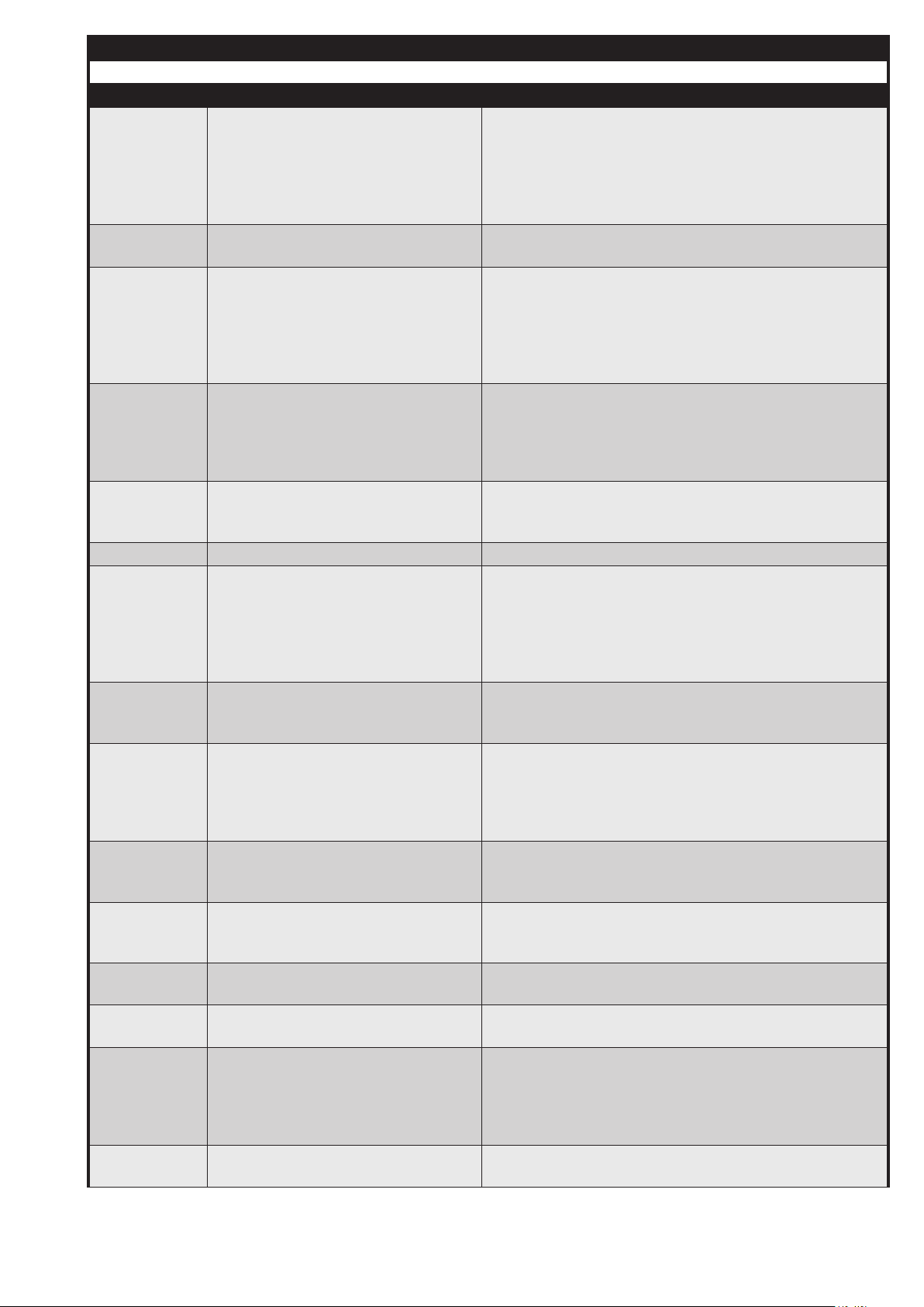
7.6 State description
MPA 5111
State xx Designation Description
00 Error or initialisation The automatic control system is in the initialisation phase
(e.g. reference run of the stepped motor) or an error is active.
If an error is active, the display shows an error message
and indicates the current fault (e.g. "F 11") instead of the
state number 00.
01 Waiting for heat request The automatic control system is ready for operation but
there is no heat request.
02 Adjustment parameter
record to stick
If the function parameter record stick (P10) is active, the
adapted parameter record is compared to the settings in
the MPA and, if necessary, the data are copied to the MPA
after a password has been entered. If necessary, the password must be entered via the display. For this, a small "c"
ashes.
03 Idle state control fan and stepped
motor
The system waits until the fan and the stepped motor are
in the OFF position If the fan has not completely stopped
after at least 2 minutes and/or the stepped motor has not
yet reached its position, the MPA is switched o and a re-
spective error message is displayed.
04 Idle state control LDW
(air pressure detector)
Depending on the operating mode of the air pressure detector (P14), it is checked if the air pressure detector reports "no air pressure"..
05 Watchdog loading phase The safety-related watchdog -circuit is activated.
06 Startup fan and stepped motor The system waits until the stepped motor has moved to its
nominal pre-aeration position and the fan has reached its
nominal pre-aeration speed.
Attention! The fan control does not check the feedback
of the fan!
07 Waiting for air pressure Depending on the operating mode of the air pressure de-
tector (P14), the system waits until the air pressure detector indicates the air pressure.
08 VPS A - Decision In this state the decision is made if a valve test during star-
tup must be carried out. See also section 7.3.2 Operation
with valve testing system. If no valve test must be carried
out, the state "Pre-aeration A" is activated.
This state lasts only 1/16 of a second.
09 VPS A - Empty the area between
the valves
V2 is opened (P42) in order to empty the area between
the valves and to compensate the possibly existing gas
pressure.
10 VPS A - Test time V1 In the dened test time (P43), no gas pressure may be built
up in the area between the valves otherwise the valve 1 is
considered as "leaking".
11 VPS A - Fill the area between the
valves
V1 is opened (P44) in order to ll the area between the
valves with gas pressure.
12 VPS A - Gas pressure detection This states lasts only one-eighth of a second and serves
for the monitoring of the gas pressure detector GDWVPS.
13 VPS A - Test time V2 The gas pressure may not drop within the dened test time
(P45) otherwise the valve 2 is considered as "leaking".
Note: When the MPA with ignition gas ame is used, also
the additional valve (= main gas ame) may be leaky al-
though the error message refers to V2.
14 Pre-aeration A This state provides a sucient pre-aeration. The dened
duration (P60) is observed for every startup.
15 … 68
Printed in Germany • Edition 02.14 • Nr. 254 722
Page 17
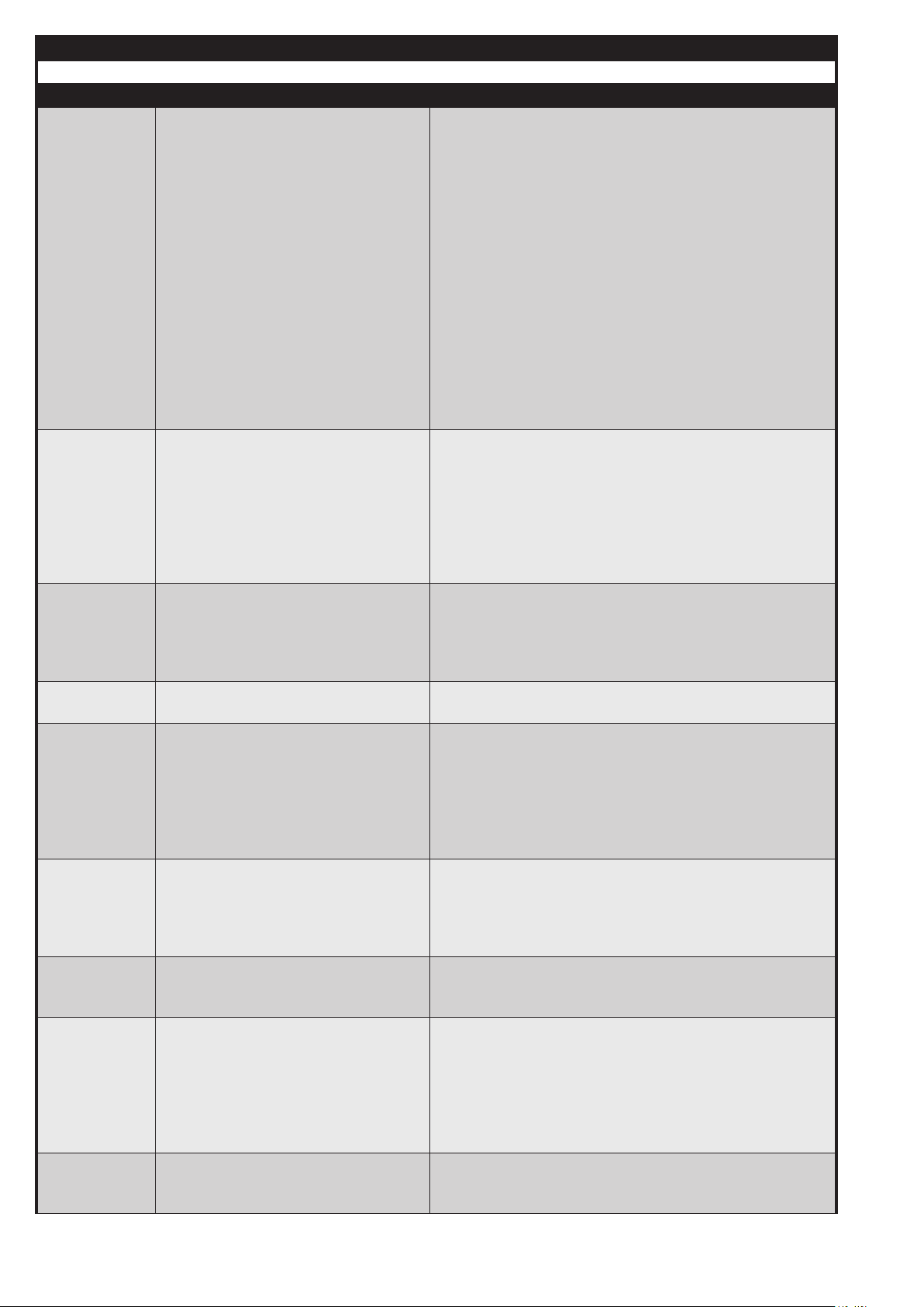
7.6 State description
MPA 5111
State xx Designation Description
15 Pre-aeration B This time is a second pre-aeration time.
Contrary to the "Pre-aeration A" state, this state is skipped
if the last switch-o of the MPA was a regular switch-o
with successful valve tightness test. Moreover, no power
failure must have been occurred since the last switch-o.
This state can be used, for example, to realise a "Reduced
pre-aeration" whose duration (P61) is dened in the state
"Pre-aeration B" and the duration of the "Pre-aeration A"
(P60) is set to 0 seconds or to the minimum required pre-
aeration time.
Please observe: The actual pre-aeration time increases by
the time for the valve tightness tests (P40 to P45) in the
startup phase, if they are activated.
See also section 7.2.3 "Operation with reduced pre-aeration".
16 Ignition position The MPA moves to the special modulation point "Ignition
position".
This state lasts as long as the stepped motor has reached
its new position and the fan works with the set speed. The
fan monitoring of the MPA waits until the fan has swung
into the regular operation (detection of upper and lower
limit in the tolerance range).
17 Gas detection GDWVPS The valve 1 is opened so that a gas pressure can be built
up between the valves and the GDWVPS can detect a gas
pressure (P62). If both types of valve test (startup P40 and
switch-o P41) are deactivated, the GDWVPS is not monitored! A bridge is not necessary.
18 Pre-ignition The ignition is already activated here (P63) without open-
ing valve 2. The valve output 1 is already active!
19 SZA - Ignition During this period (P64), the ignition remains active and
valve 2 is open. The gas can ow now and a ame can be
generated.
This state is 0.5 seconds shorter than the time set in P64
because the safety time for startup is divided in state 19
and 20!
20 SZA - Flame detection The ignition is deactivated 0.5 seconds before the end
of the safety time for startup (P64) and the procedure for
ame detection (ionisation input) is started.
If an ionisation current is detected, the MPA reports a
ame.
21 Stabilisation ame A The ame can be stabilised with the help of a congurable
special modulation point. The duration of the stabilisation
phase (P65) can be congured.
22 Stabilisation ame B Another special modulation point can be dened for this
stabilisation phase (P66). When using the MPA with pilot
burner, this state can be used to activate the main ame.
The main gas valve (=additional valve) can be activated af-
ter an adjustable time (P50 and P52) after the changeover
to the state.
See also section 7.4.4 Operation with ignition gas ame
23 Changeover to the standard mode The MPA leaves the current special modulation point and
moves to the start simulation point of the standard mode
(P67).
Printed in Germany • Edition 02.14 • Nr. 254 722
16 … 68
Page 18
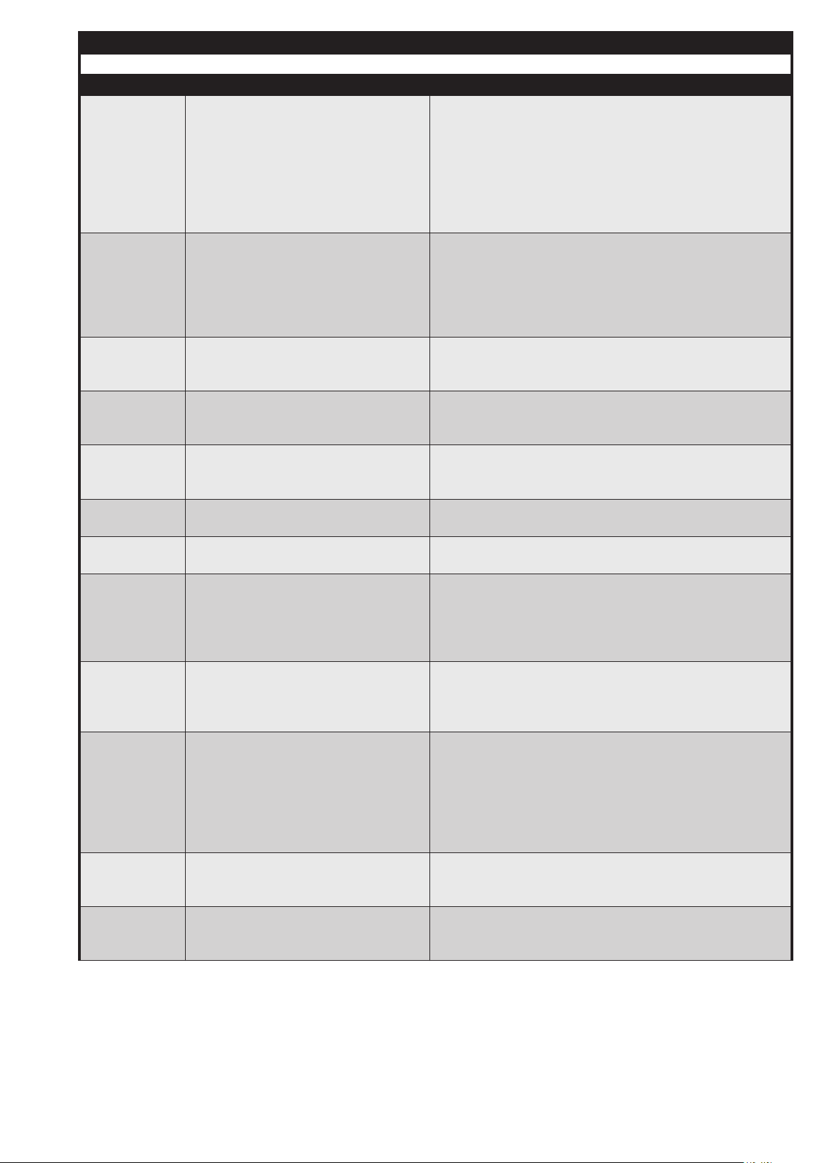
7.6 State description
MPA 5111
State xx Designation Description
24 Standard mode In this mode, the MPA can be modulated via several types
(see P70 to P76, especially P72).
A voluntary switch-o after a dened time can be activated
(P70). If this time is set to a maximum of 23 hours and 59
minutes, the MPA is in the intermittent mode.
Continuous operation (≥ 24 h) is only possible using acontinuous operation stick, see section 8.11
25 Changeover after regular switch-oThis state can be used to dene the modulation degree
after a regular switch-o (see also P80 and P81).
Possible application: In order to avoid a switch-o when
the system is under full load, this state can be used to
reduce (or increase) the power to a dened value.
26 VPS B - Decision In this state the decision is made if a valve test must be
carried out. See Operation with valve testing system.
This state lasts only 1/16 of a second.
27 VPS B - Empty the area between
the valves
V2 remains open (P42) in order to empty the area between
the valves and to compensate the possibly existing gas
pressure.
28 VPS B - Test time V1 In the dened test time (P43), no gas pressure may be built
up in the area between the valves otherwise the valve 1 is
considered as "leaking".
29 VPS B - Fill
the area between the valves
V1 is opened (P44) in order to ll the area between the
valves with gas pressure.
30 VPS B - Gas pressure detection This states lasts only one-eighth of a second and serves
for the monitoring of the gas pressure detector GDWVPS.
31 VPS B - Test time V2 The gas pressure may not drop within the dened test time
(P45) otherwise the valve 2 is considered as "leaking".
Note: When the MPA with ignition gas ame is used, also
the additional valve (= main gas ame) may be leaky al-
though the error message refers to V2.
32 Follow-up time During this time (P82), a ame signal may be present from
the previous mode caused by e.g. existing residual gas in
the combustion chamber. The external light monitoring is
only started in the following state.
33 Post-aeration In this state, the post-aeration of the combustion chamber
is carried out (P83).
17 … 68
In this state, no ame must be detected. Since the duration of the state with the setting P83=0 is only a few milli-
seconds, the MPA reacts also to external light if "no" post-
aeration is congured.
34 Restart protection In this state, the temperature controller is not evaluated,
that means if another heat request is sent or activated, the
automatic is not restarted.
35 Lack of gas GDWMIN If the input GDWMIN of the automatic system is not closed,
the automatic system waits in this state until the gas pressure is detected.
Printed in Germany • Edition 02.14 • Nr. 254 722
Page 19

7.6 State description
MPA 5111
State xx Designation Description
36 Waiting program The MPA switches to this state if a lack of gas on the GD-
WVPS (depending on P46) or an open safety chain has
been detected during startup.
The MPA remains in this state for a certain waiting time
and then carries out another restart test. The number of
restart tests is congurable (P90).
The waiting time duration depends on the number of wait-
ing times that have been executed before. The rst time,
the waiting time is 2 minutes, the second time 5 minutes
and the third time 1 hour and afterwards a time duration
dened by a parameter is applied. If the waiting time dened by a parameter (P91) is shorter than the rmly dened
times of the rst 3 restart tests, these are also reduced to
the parameter-dened time.
The respective waiting time can be interrupted by setting
the temperature controller to OFF (OFF depends on the
operating mode in P15!).
The waiting program start from the beginning if the automatic system
a) has been separated from the mains,
b) has been unlocked or
c) has reached the standard mode after a restart test.
Printed in Germany • Edition 02.14 • Nr. 254 722
18 … 68
Page 20

8 Parameters
8.1 P1x General parameters
Parameter
Designation Description Setting / Examples
P1x
P10 Parameter stick: ac-
tive
P11 Restart
attempts
P12 Restart
attempts due to a
missing ame
P13 Restart
attempts after the
ame has gone out
Indicates if the parameter record
stick is to be checked or copied,
if necessary, during the restart
phase. See also section 8.11 Stick
for parameter record and continuous run.
Here you can set the number of restart attempts the MPA is allowed to
be carried out before the fault switch-
o is activated (state "Error").
The anti-oscillation counter is reset
to this value as soon as the MPA has
reached the state "Standard mode"
or the MPA has been unlocked.
The number of restarts is internally
counted by means of the anti-oscillation counter.
The number of restart attempts
(P11) can be limited here for the
special case that no ame has been
generated during the safety time.
For this purpose, the restart counter is internally implemented. The
anti-oscillation counter as well as
the restart counter are activated!
The number of restart attempts
(P11) can be limited here for the
special case that a ame has gone
out.
For this purpose, also the restart
counter is internally used. The antioscillation counter as well as the
restart counter are activated!
Setting 0:
Parameter stick deactivated
Setting 1:
Parameter stick active
Example:
P11 = 5, P12 = 1
During the rst start phase, no
ame is generated → 1. Restart
attempt → Error idle state control
LDW → 2. Restart attempt → Error
idle state LDW 3. Restart attempt
After the third restart attempt LDW
OK, there is still no ame Automatic
burner control is locked.
Example:
P11 = 5, P13 = 1
Flame gone out during operation
1. Restart attempt Error Idle state
control LDW 2. Restart attempt
Error Idle state control LDW 3. Restart attempt No ame is gener-
ated after the third restart attempt
LDW OK Automatic burner control
is unlocked.
19 … 68
Printed in Germany • Edition 02.14 • Nr. 254 722
Page 21

8 Parameters
8.1 P1x General parameters
Parameter
Designation Description Setting / Examples
P1x
P14 Operating mode LDW The LDW (air pressure detector)
must be activated!
It must be set in a way to guarantee
an activation also if there is only a
minimum power.
Basically, DUNGS recommends to
use the operating mode 0. Exceptions can partly be accepted. The
LDW can be operated in 4 operating modes.
Setting 0:
The LDW is active and is monitored.
Setting 1:
No idle state control is carried out.
Otherwise, the LDW is permanently active. Attention! Ifthe LDW is
jammed or if there is a wire bridge
there will be no error message during the startup phase!
Setting 2:
The LDW is monitored only during
startup, that means only to the state
"Waiting for air pressure". In the fol-
lowing state, an LDW which is not
active does NOT result in an error
message.
Setting 3:
The LDW is monitored during the
startup phase if the current modulation degree is higher than the start
modulation degree in the standard
mode. That means that, in case of
small modulations, the LDW can
switch-o without generating the
error message "No air pressure"
and deactivating the MPA.
Moreover, the LDW is not monitored after the pre-aeration until the
standard mode is reached and, in
case of a regular switch-o, it is not
monitored until the post-aeration is
reached.
Attention! This operating mode is
only allowed, if the fan is controlled
(internal plausibility check of the
feedback signals).
Printed in Germany • Edition 02.14 • Nr. 254 722
20 … 68
Page 22

8 Parameters
8.1 P1x General parameters
Parameter
Designation Description Setting / Examples
P1x
P15 Operating mode
Temperature controller
The temperature controller can be
operated in the following operating
modes:
Setting 0:
The temperature controller is always switched OFF, independently
of the hardware input
Setting 1:
The temperature controller is always switched ON, independently
of the hardware input
Setting 2:
The temperature controller is OFF,
however, this operating mode must
be dened again within one minute.
Otherwise the automatic burner
control switches to the setting 3.
This can happen, for example, if
the communication is interrupted.
Setting 3:
The temperature controller is assigned to the hardware input "Temperature controller".
P16 Parameter record:
Customer ID
Internal setting (cannot be changed)
4...255:
These values are used for the time
monitoring for the setting 2, that
means that, if the parameter P15
is congured to the setting 2, the
MPA changes this setting to values
between 4 and 255 and reaches
the setting 3 after 1 minute (cyclical
decrementation).
This parameter indicates the cus-
tomer ID dened in the parameter
record stick. This allows to assign a
parameter record to a customer.
0 means "No parameter record
found" or "Startup (state 2) not yet
carried out".
The parameters P16 and P17 are
read and updated during each startup (state 2). If no parameter stick
was found, this value is 0. The value is also 0 if no startup has been
carried out since the last processor
start, that means if the automatic
burner control never has reached
the state 2. This applies also for a
processor start, for ex. after a safe-
ty switch-o!
21 … 68
Printed in Germany • Edition 02.14 • Nr. 254 722
Page 23
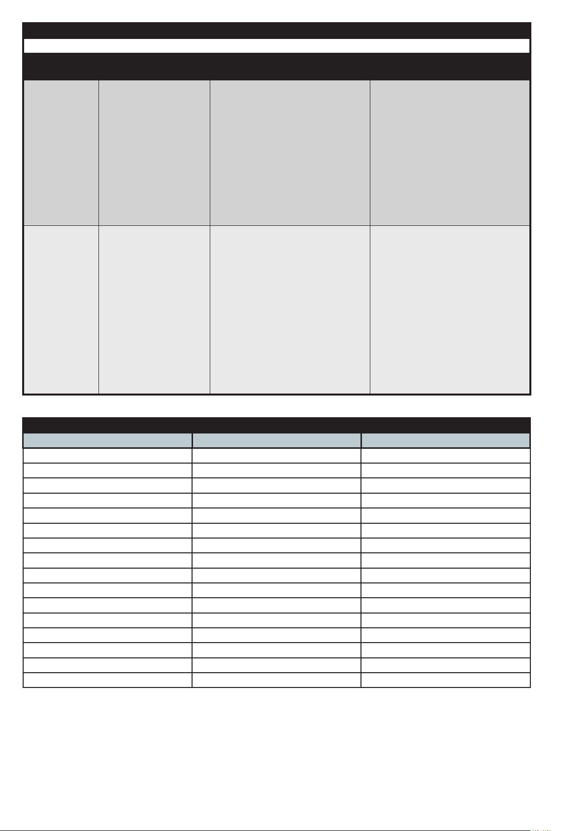
8 Parameters
8.1 P1x General parameters
Parameter
Designation Description Setting / Examples
P1x
P17 Parameter record:
Record ID
P18 Operating mode
PWM outputs
This parameter indicates the
record ID dened in the parameter
record stick. This allows to distinguish several parameter record
versions of a customer.
0 means "No parameter record
found" or "Startup (state 2) not yet
carried out".
The behaviour is the same as described in P16.
Using this parameter, the behaviour of the outputs PWM2 and
PWM3 can be changed in order to,
for ex., activate analogue outputs
correctly.
The external function activated by
PWM2 and PWM3 are dened by
the plugged-in extension module
which allows to activate each of
the two outputs by a digital signal
(PWM for fan, frequency converter,
...) or by an analogue signal with
0...10 V or 4...20 mA.
The correct setting for P18 is indicated in the following table
Setting P18 Conguration PWM2 as: Conguration PWM3 as:
0 OFF OFF
1 OFF PWM signal
2 OFF Analogue 0...10 V
3 OFF Analogue 4...20 mA
4 PWM signal OFF
5 PWM signal PWM signal
6 PWM signal Analogue 0...10 V
7 PWM signal Analogue 4...20 mA
8 Analogue 0...10 V OFF
9 Analogue 0...10 V PWM signal
10 Analogue 0...10 V Analogue 0....10 V
11 Analogue 0...10 V Analogue 4....20 mA
12 Analogue 4...20 mA OFF
13 Analogue 4...20 mA PWM signal
14 Analogue 4...20 mA Analogue 0...10 V
15 Analogue 4...20 mA Analogue 4...20 mA
P18 Example: The extension mod-
ule MPA-EM1/3 is equipped with a
conversion from PWM2 to 0...10 V
and with a conversion from PWM3 to
4...20 mA. The correct setting results
from:
P18 = 11 ( for MPA-EM1/3)
P18 Note
If the conguration "4...20 mA" is
selected for a voltage output, this
corresponds to a voltage output of
2...10 V.
If the conguration "0...10 V" is
selected for a current output, this
corresponds to a current output of
0...20 mA.
Printed in Germany • Edition 02.14 • Nr. 254 722
22 … 68
Page 24

8.2 P2x - Fan
The MPA51 controls the fan by
means of PWM signal and evaluates
a hall sensor signal delivered by the
fan in form of a rotation speed.
The number of feedback pulses per
rotations has to be indicated in P24.
In case of wrong values in P24, the
MPA calculates a wrong rotation
speed!
The MPA can control or regulate the
fan (PI controller).
8 Parameters
8.2 P2x Fan
Parameter
Designation Description Setting
P2x
P20 Fan: Control Indicates if the fan is controlled
or regulated. For the regulation, a
feedback signal to record the fan
speed is required!
P21 Fan: Delay / ramp a) For fan control:
This parameter is used to smoothen
jumps of the fan activation signal
(PWM signal).
b) For fan regulation:
The desired fan behaviour can be
reached by means of the KP and
TN factors. However, jumps in the
setpoint values for the fan can be
slowed down via the ramp delay
function.
Setting 0: Control
Setting 1: Regulation
Setting 0 means that even big jumps
are immediately transformed. The
bigger the set value the slower the
PWM signal is adapted to its new
nominal value in case of changes.
The value of the parameter should
be set to 0.
23 … 68
Printed in Germany • Edition 02.14 • Nr. 254 722
Page 25

8 Parameters
8.2 P2x Fan
Parameter
Designation Description Setting
P2x
P22 Fan: KP factor a) For fan control:
This factor is only relevant if the fan
is controlled!
b) For fan regulation:
The Kp factor denes the eect of
the dierence between nominal
value and actual value on the regulating value.
Kp is no proportional factor:
• small Kp values result in a slow
adaptation to the nominal value.
• big Kp values result in a fast regulation, but can also create an overshooting
Always observe the interaction between the P and I part, that means
that a separate consideration of Kp
and Tn is not possible!
P23 Fan: TN factor a) For fan control:
This factor is only relevant if the fan
is controlled!
P24 Fan: Pulses per rota-
tion
b) For fan regulation:
The Tn factor denes the eect of
the history, that means the accu-
mulated dierence between the
nominal and the actual value (integration), to the regulating value.
Tn is a division factor:
• small Tn values result in a fast but
more instable regulation. Resonance and swinging-up systems
are the possible eects of wrong
values.
• big Tn factors stabilise the system.
Always observe the interaction between the P and I part, that means
that a separateconsideration of Kp
and Tn is not possible!
a) For fan control:
This value is only relevant if the
fan speed is to be recorded! The
recording has no inuence on the
behaviour of the MPA.
b) For fan regulation:
The number of impulses per rotation provided by the fan must be set
here.
If an incorrect value is indicated,
the determined speed is incorrectly
calculated.
Printed in Germany • Edition 02.14 • Nr. 254 722
24 … 68
Page 26
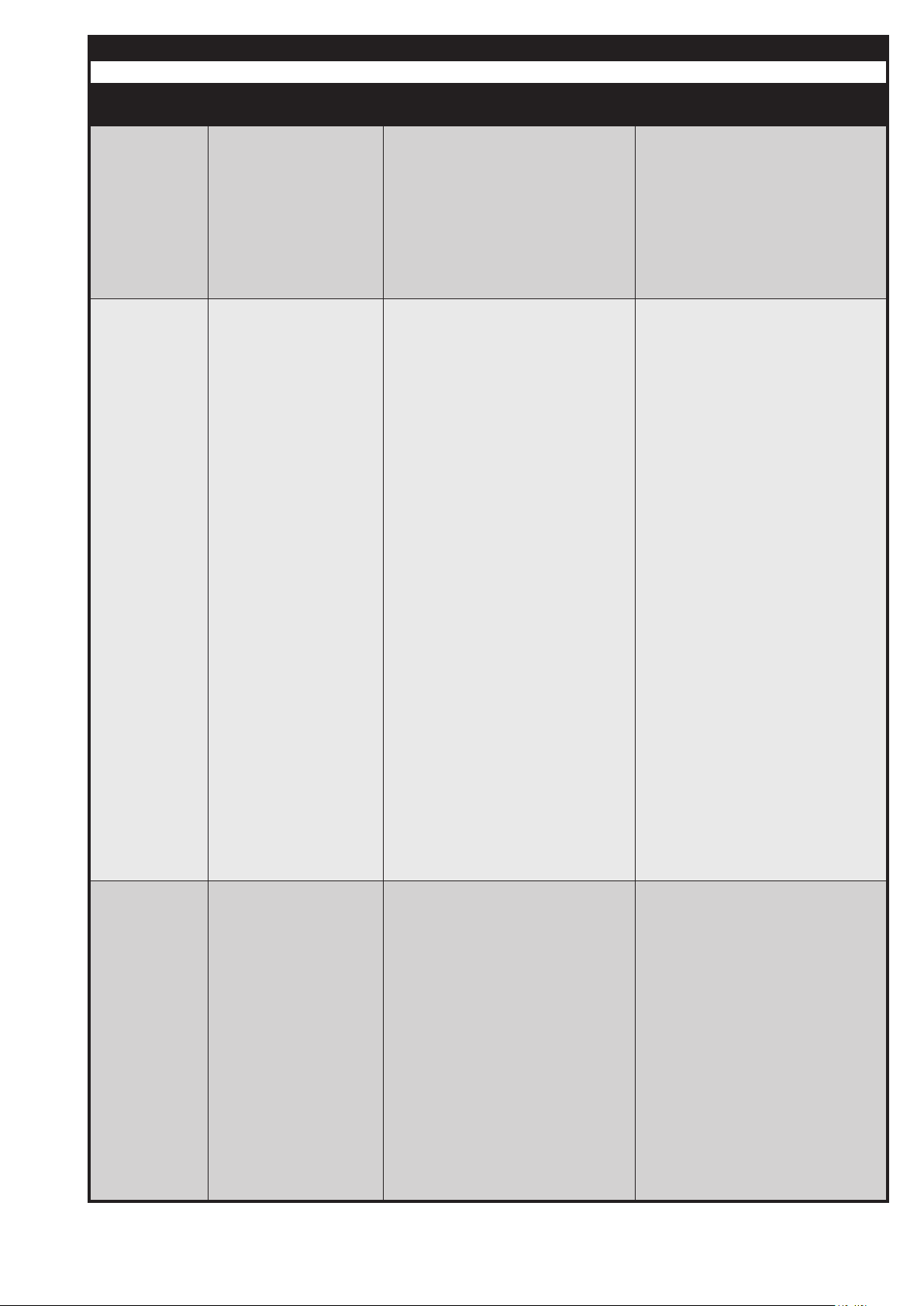
8 Parameters
8.2 P2x Fan
Parameter
Designation Description Setting
P2x
P25 Fan: allowed toler-
ance
a) For fan control:
not relevant
b) For fan regulation:
Here the allowed deviation between
the fan speed and the current nomi-
nal speed is dened. If the speed
has been outside this tolerance
range for a longer time period, the
MPA is switched o.
P26 Fan: Min. speed. a) For fan control:
The minimum PWM activation
can be dened. If this value is not
reached, the fan does not work correctly. Typically, a fan only works
properly if the PWM signal reaches
approx. 10 to 20 %. If this value is
not reached, the fan begins to oscillate or does not work.
If a fan activation lower than this
value is calculated due to the settings in the curve segment, the
MPA is switched o displaying a
corresponding error message.
Attention! There is no direct relation to the speed at a modulation
degree of 100 %!
b) For fan regulation:
A minimum speed can also be
entered here If this value is not
reached during the calculations
from the curve segment, the MPA
creates a corresponding error message.
Attention! There is no direct relation to the speed at a modulation
degree of 0 %!
P27 Fan: Max. speed a) For fan control:
This parameter should be set to 100
%. If another value is entered here,
this will inuence the programmed
values in the curve segment!
b) For fan regulation:
Here, the maximum speed of the
fan must be entered. A fan reaches
the maximum speed if it is activated
with 100% PWM and the air ow is
blocked.
25 … 68
Attention! There is no direct relation to the speed at a modulation
degree of 100 %! (apply for adjustment a) and b))
Printed in Germany • Edition 02.14 • Nr. 254 722
Page 27
8 Parameters
8.3 P3x Stepped motor
Parameter
Designation Description Setting
P3x
P30 Stepped motor:
Selection Stepped motor type
Type
Possible types:
Parameter value Conguration PWM2 as: Conguration PWM3 as:
0 No stepped motor –
1 reserved –
2 SAD 1.2 or SAD 3.0 (IP54) Standard / delivery position
3 SAD 1.2 or SAD 3.0 (IP54) "changed" reference point
4 SAD 1.5 or SAD 3.0 (IP40) *1 Standard / delivery position
5 SAD 1.5 or SAD 3.0 (IP40) *1 "changed" reference point
6 SAD 15 Standard / delivery position
7 SAD 15 "changed" reference point
8 SAD 1.2 WG (Q3) or SAD 3.0 WG (Q3) Standard / delivery position
9 SAD 1.2 WG (Q3) or SAD 3.0 WG (Q3) "changed" reference point
10 SAD 10 WG (Q3) Standard / delivery position
11 SAD 10 WG (Q3) "changed" reference point
Attention!
A stepped motor must only be connected to the MPA or separated from
the MPA if it is disconnected from the
mains.
The change of this parameter only
becomes eective after a restart of
the MPA. The MPA can be restarted
by interrupting the power supply or
by means of the "Extended unlocking" (press the unlock key for 5
seconds).
If this parameter is programmed for
a specic stepped motor type, this
stepped motor must be connected.
An incorrect conguration of this
parameter can lead to an overspeed-
ing which may destroy the incorrectly
congured stepped motor!
If the selected stepped motor is not
found, it is not possible to change the
stepped motor via the display of the
MPA51xx. But there is the possibility
to correct the parameters using the
VisionBox.
Further information can be found in
the annex 13: "Stepped motors".
*1 Attention!
The stepped motors SAD 1.5 and
SAD 3.0 with IP40 have another step
width.
If the nominal value is 90° (VisionBox), these stepped motors have an
actual angle of 93.37°, that means
that all angle indications referring to
nominal and current position must be
converted to the actual position using the factor 0.963957. Vice versa,
the factor 1.03739 is applicable.
Printed in Germany • Edition 02.14 • Nr. 254 722
26 … 68
Page 28

8 Parameters
8.3 P3x Stepped motor
Parameter
Designation Description Setting
P3x
P31 Stepped motor:
allowed tolerance
This value denes the highest allowed deviation between the nominal value and the actual value of the
determined stepped motor without
activating a safety switch-o
27 … 68
Printed in Germany • Edition 02.14 • Nr. 254 722
Page 29

8 Parameters
8.4 P4x - VPS
Parameter
Designation Description Setting
P4x
P40 VPS: active during
startup
Setting 0: The valve test is not
always carried out during startup
(depending on P41)
Setting 1: The valve test is carried
out in each startup phase
P41 VPS: active after
switch-o
Setting 0: The valve test is never
carried out after a regular switch-
o
Setting 1: The valve test is carried
out after every switch-o and, if
necessary, in the startup phase
(see section "Operation with valve
testing system")
P42 VPS: Duration Emp-
tying area between
valves
Indicates how long V2 will be
opened in order to let the possible
overpressure escape into the combustion chamber.
P42 VPS: Test time V1 Indicates the duration of the test in
order to nd out whether a pressure
is being built up in the area between
the valves.
P44 VPS: Duration Filling
area between valves
Indicates how long V1 will be
opened in order to let gas ow into
the area between the valves.
P45 VPS: Test time V2 Indicates the duration of the test in
order to nd out whether gas escapes from the area between the
valves.
P46 VPS: GDWVPS as
minimum monitoring
The GDWVPS input can also be
used for the monitoring of the minimum gas pressure. For doing this,
this parameter must be set to "Active".
If this value is inactive, the GDWVPS input is only evaluated during the valve test.
For the calculation of these parameters or for the settings recommended by DUNGS, see 7.4.2 Operation with valve
testing system.
Printed in Germany • Edition 02.14 • Nr. 254 722
28 … 68
Page 30

8 Parameters
8.5 P5x - Additional valve
Parameter
Designation Description Setting
P5x
P50 Additional valve:
Activation state
P51 Additional valve: De-
activation state
P52 Additional valve:
Time-delayed activation
P53 Additional valve:
Time-delayed deactivation
In the state dened here, the output
of the additional valve is activated.
Attention! The actual activation
can take place with a delay in time!
See also P52.
In the state dened here, the output
of the additional valve is deactivated.
Attention! The actual deactivation
can take place with a delay in time!
See also P53.
Using this parameter, the time-
delayed activation is dened, that
means that the additional valve is
switched on a set time period after
the activation of the state dened in
P50.
Attention! If the duration of the
state is shorter than the dened
delay, the additional valve is only
activated with the start of the sub-
sequent state. For example, if the
state "Pre-aeration A" is set with a
delay in time of 40 seconds (P50
and P52), the pre-aeration time A,
however, (P60) lasts only 30 seconds, the additional valve is already activated after 30 seconds
when the next state is started (e.g.
"pre-aeration B) and not 40 seconds after the start of the state
"pre-aeration A".
Same function as P52, but with a
delay in time for the switch-o key.
29 … 68
Printed in Germany • Edition 02.14 • Nr. 254 722
Page 31

8 Parameters
8.6 P6x - Startup
Parameter
Designation Description Setting
P6x
P60 Pre-aeration time A Denes the duration of the pre-aer-
ation A. For the dierence between
pre-aeration A and B, see section
"Operation with reduced pre-aeration"
P61 Pre-aeration time B Denes the duration of the pre-aer-
ation B. For the dierence between
pre-aeration A and B, see section
"Operation with reduced pre-aeration"
P62 Duration gas detec-
tion startup phase
Denes the duration of the gas
detection GDWVPS in the section
7.5 State 17: "Gas detection GDWVPS"
Here, the valve 1 is opened in order
to let gas ow into the area between
the valves. The GDWVPS must detect a gas pressure at the end of the
state otherwise V2 is not opened
due to a lack of gas and the MPA
switches to the waiting program
(see state 36: "Waiting program").
If both types of valve test are deactivated, the GDWVPS is not evaluated and the time duration can be
set to 0!
P63 Pre-ignition time Denes the duration of a pre-igni-
tion.
P64 Safety time for star-
tup phase
Denes the duration of the safety
time for startup phase (SZA).
Attention! This duration is divided
in the two states "SZA ignition" and
"SZA ame detection" while the
state "SZA ame detection has al-
ways a duration of 0.5 seconds
P65 Stabilisation time A Denes the duration of the stabi-
lisation time A. For the dierence
between stabilisation time A and B,
see section 7.2.4 "Operation with
ignition gas ame.SDSq
P66 Stabilisation time B Denes the duration of the stabi-
lisation time B. For the dierence
between stabilisation time A and B,
see section 7.2.4 "Operation with
ignition gas ame.SDSq
P67 Start modulation de-
gree Standard mode
Indicates the modulation degree
that the automatic burner control
should adopt in the standard mode
after the creation of the ame and
after the stabilisation times A and B
have elapsed.
As soon as the standard mode has
been reached, there are several
options to modiy the modulation
degree (P72).
Printed in Germany • Edition 02.14 • Nr. 254 722
30 … 68
Page 32

.
8 Parameters
8.7 P7x - Operation
Parameter
Designation Description Setting
P7x
P70 Duration Standard
mode
P71 Modulation degree:
new nominal value
P72 Modulation degree:
Type of modication
Here you can dene whether the
automatic burner control should
carry out a voluntary switch-o. If
yes, dene the operating time (in
minutes)
This value can be used to dene a
new modulation degree. As soon
as the automatic burner control has
recognised a new value, this param-
eter is reset to 0xFFFF (=65535).
Denes the type of modulation de-
gree that is predened for the op-
eration:
Typical settings:
0xFFFF = 65535 Continuous operation / no switch-o.
1439 = 23h 59 min intermittent op-
eration.
Also other values are possible, e.g.
60 = switch-o after 1 hour.
Continuous operation (≥ 24 h) is
only possible using acontinuous
operation stick, see section 8.11
Setting 0: Externally, that means
only by means of one of the communication interfaces to a new absolute value
*1: The analog value is accepted as
soon as the detected modication is
> 5 % of the nal value (e.g. > 1 mA
at 4...20 mA). Modications < 5 %
are accepted only after a certain time
(see P74).
Modications between 0% and
+0.5% are considered as "Noise" and
are eliminated.
Setting 1: Plus / Minus, that means
via a communication interface to an
absolute value or upwards (plus) or
downwards (minus) relative to the
currently set modulation degree via
the two corresponding hardware
inputs.
Setting 2: By means of a suitable
extension module via an analogue
input to an analogue predened
absolute value with the full range of
values, for example 0 V (0 %) to 10
V (100 %). *1
Setting 3: By means of a suitable
extension module via an analogue
input to an analogue predened
absolute value with a limited range
of values, for example 4 mA (0 %)
to 20mA (100 %). *1
31 … 68
Printed in Germany • Edition 02.14 • Nr. 254 722
Page 33

8 Parameters
8.7 P7x - Operation
Parameter
Designation Description Setting
P7x
P73 Modulation degree:
Step width of the
modication
P74 Modulation degree:
Interval Acceptance
of analogue values
Denes the maximum step width
of a modulation degree modica-
tion without intermediate control.
a) By means of relative modication via the plus or minus input, the
nominal value is modied upwards
or downwards by the value dened
in P73. Further modications are
accepted as soon as the fan and
the stepped motor work again in
the allowed tolerance range (P25
and P31).
b) Due to new absolute setpoints,
the MPA modies its current modulation degree step by step by the
value dened here until the new
setpoint is reached. After each
intermediate step, the automatic
burner control waits until the fan
and the stepped motor work in the
allowed tolerance range (P25 and
P31).
Denes the time interval for the
evaluation and acceptance of the
analogue input in the operating
mode "Modulation degree setpoint
via analogue input" (setting 2 and
3 of P72).
P75 Modulation degree:
Lower limit
P76 Modulation degree:
Upper limit
Particularly for the operation with
stepped motor, this time interval
should not be too short in order to
avoid repeated one-step movements forward and backward of the
stepped motor.
See also *1 of P72
Denes a lower limit below which
the modulation degree must not
fall. Setpoints which fall below this
limit are adjusted to the allowed
range.
Example: Lower limit = 10 %, new
setpoint = 8 % Automatic burner
control corrects the setpoint to 10 %.
Denes an upper limit of the modu-
lation degree which must not be
exceeded. Setpoints which are outside this limit are adjusted to the allowed range.
Example: Upper limit = 90 %, new
setpoint = 97 % Automatic burner
control corrects the setpoint to 90 %.
Printed in Germany • Edition 02.14 • Nr. 254 722
32 … 68
Page 34
8 Parameters
8.8 P8x - Switch-o
Parameter
Designation Description Setting
P8x
P80 Regular switch-o:
Transition time
P81 Regular switch-o:
Power during transi-
tion
Using this parameter, a transition
time can be activated in which the
MPA remains after the failure of the
temperature controller / heat request. The ame remains burning.
During this time, the MPA moves to
the modulation degree dened in
P81.
This function can be used to avoid
that the MPA switches o in an undesired modulation degree.
Attention! This setting can only be
applied for the regular switch-o. In
case of a safety switch-o, the MPA
switches o without changing the
modulation degree to the desired
setting.
This value denes the desired
modulation degree for a regular
switch-o. Chose the value so that
no undesired noise or vibrations
are generated during the regular
switch-o.
Attention! A suciently long transition time after a regular switch-o
(P80) must be dened in order to
reach this modulation degree.
Attention! This setting can only be
applied for the regular switch-o. In
case of a safety switch-o, the MPA
switches o without changing the
modulation degree to the desired
setting.
P82 Follow-up time See state: "Follow-up time".
Denes the time during which the
external light is not monitored after
a regular switch-o.
P83 Post-aeration time Denes the post-aeration time after
a regular switch-o.
Attention! After a safety switch-o,
this post-aeration is not carried
out!
P84 O-period before
restart
Denes the duration of the compulsory waiting time until the automatic burner control is allowed to start
again.
33 … 68
Printed in Germany • Edition 02.14 • Nr. 254 722
Page 35
8 Parameters
8.9 P9x - Waiting program
Parameter
Designation Description Setting
P9x
P90 Waiting program:
Restart
attempts
P91 Waiting program:
Duration
Denes the number of restart attempts after the errors "Lack of
gas on GDWVPS" or "Safety chain
open" until the MPA switches to the
fault switch-o.
The setting 0xFF and 255 means
that an innite number of restart attempts can be carried out without
activating the fault switch-o of the
MPA.
Denes the time period after which
the MPA carries out another restart
attempt.
Attention! For the rst restart attempts, the duration can dier from
this setting! See state: "Waiting
program".
Printed in Germany • Edition 02.14 • Nr. 254 722
34 … 68
Page 36

8 Parameters
8.10 Internal parameters
Parameter
Designation Description Setting
P10
P250 Internal parameters:
Modulation degree
modication allowed
P251 Parameter stick:
Password
P252 Internal parameters:
Programming of
curves
Please do not change!
Please do not change!
Please do not change!
35 … 68
Printed in Germany • Edition 02.14 • Nr. 254 722
Page 37

8.11 Parameter record and stick
for continuous run
The MPA51xx oers the possibility to
load predened parameter records
from a stick.
The parameter record stick is adjusted during the startup phase (state
2). That means that, if the parameter
P10 is active (=1), the data of the
stick are compared with the data of
the automatic burner control. If deviations are detected, the data on the
stick are copied into the automatic
burner control. To copy the data, a
password which is adapted to the
stick must be entered (a "c" ashes
in the display).
If the parameter is not active (= 0),
the function "Parameter record stick"
is considered as not desired. Therefore, the data are not compared and
not copied. The automatic burner
control works with the data stored in
the MPA.
The continuous run function is
only possible using a stick. There
is always a check (independent of
P10) whether a continuous run stick
is plugged in. At the same time, this
can also be a parameter record stick.
It is not possible to copy a data
record from the MPA to a parameter
record stick. Parameter records
must be generated and created by
DUNGS.
Attention!
The parameters in the MPA only
comply with the parameters of the
parameter record stick if the parameter P10 is active!
Attention!
There are parameter record sticks
which do not compare and copy all
parameters but only a part quantity.
Please observe which parameters
are compared and copied by the
plugged-in parameter record stick
and which not.
a) Conguration of the burner ver-
sion with astick permanently
plugged in:
As soon as the stick is plugged
in and the password is entered,
a specic parameter record is
transmitted to the MPA. Is is possible to modify parameters but,
during the next startup phase
(state 2), the modications are
recognised and the automatic
burner control copies the data
from the stick.
If the stick is removed, the MPA
does not start again.
Attention!
According to the stick, some
parameters are not considered
during the adjustment process
(stick with a part quantity of the
parameters).
Attention!
For this application, the param-
eter P10 must never be deactivated!
This version is suitable for a per-
manent denition of the burner.
When a (defective?) MPA is replaced, the stick connected to the
burner guarantees that the new
MPA uses the same settings than
the old one.
b) Conguration of the burner version
by a stick which is used only
once:
As soon as the stick is plugged
in and the password is entered,
a specic parameter record is
transmitted to the MPA (P10 must
be active).
During a restart (recommended!)
the new parameter record is again
compared in state 2 with the values on the stick and thus the adjustment process is controlled. If
a restart is carried out or not, the
user has to check the new data
and to enable the new settings
by deactivating the parameter 10.
Note: the parameter view in the
VisionBox must be updated!
After the unique copy process
and the deactivation of the parameter 10, the stick may remain
plugged in or can be replaced by
another stick.
Even if the stick remains plugged
in, modications of the parameters are not recognised. For
another data adjustment with the
MPA, the parameter 10 must be
activated. During the next startup
phase
(state 2), the MPA carried out an-
other data adjustment (protected
by a password).
Attention!
According to the stick, some
parameters are not considered
during the adjustment process
(stick with a part quantity of the
parameters).
This version is suitable to pro-
gram a unique conguration in a
MPA, for example, in the produc-
tion during a rst startup, as a
"Return-To-Factory-Settings function",...
Attention!
A special access level is dened
for activation or deactivation of the
parameter records on the extension
module.
A parameter record stick can be
used for the following applications:
Printed in Germany • Edition 02.14 • Nr. 254 722
36 … 68
Page 38
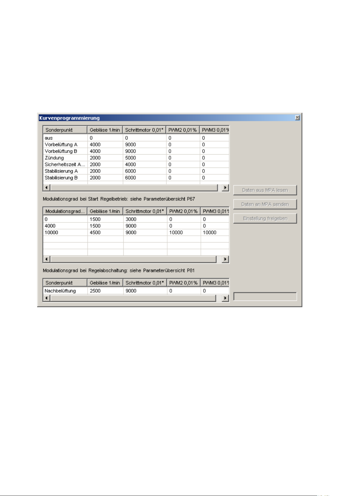
9 Curve settings/
modulation degree
9.1. Stick and VisionBox
The programming of curves is only
possible using the VisionBox and a
parameter record stick! The curves
cannot be processed via the 3 segments display!
It is possible to plug in the desired
parameter record stick or to start
the respective interface of the application software of the connected
VisionBox under "View Programming of curves".
37 … 68
Here you can:
a) read the current settings of the
MPA,
b) change the setting of the modula-
tion degree point and the special
points by a right mouse click,
c) transmit the modied settings
temporarily to the MPA for test
purposes.
Attention! Settings are reset after
a restart of the MPA!
Printed in Germany • Edition 02.14 • Nr. 254 722
d) apply the modied settings in the
MPA.
Attention! Applied settings are
permanently active and remain
stored.
PWM 2 and PWM 3 can be used according to the connected extension
module for analogue output signals
(for ex. 0...10 V or 4...20 mA).
Page 39

9.2 Denition of terms
9.2.1 Burner capacity
Indicates the capacity and/or heat
produced by the burner. Typically,
the capacity is indicated in kWh.
9.2.2 Modulation degree
Normally, there is a dierence between the modulation degree and
the burner capacity. However, it is
possible to program the MPA in a
way so that the two values comply
with each other!
It is possible to predene the so-
called "modulation degree" of the
burner in the state "Standard mode"
on the MPA using several options
(see P72).
A specic combination of nominal
value for the fan, stepped motor
position and nominal value for PWM
2 and 3 is assigned to each modulation degree via the curve segment.
That means that, if a new modula-
tion degree is predened, the MPA
calculates the corresponding nominal values for the fan, for the stepped
motor, for PWM 2 and PWM 3.
Afterwards, the fan, the stepped motor, PWM 2 and PWM 3 are adapted
to the new value.
The modulation degree can be
changed in the range between 0 %
and 100 %.
Attention!
0 % (100 %) do not comply necessarily to the lowest (highest) possible
burner capacity! The actual burner
capacity depends on the combina-
tion of all inuencing values.
But the MPA can be set in a way
that 0 % of the modulation degree
complies to the minimum burner
capacity and 100% to the maximum
burner capacity. Minimum means in
this case not "Flame O" / " No heat"
but "smallest possible ame". Also
the modulation degrees between
0% and 100% can be programmed
proportionally to the burner capacity.
A relationship between modulation
degree and burner capacity, however, is not necessary for the MPA.
9.2.3 Curve point
In the MPA, up to 30 curve points
can be programmed for the standard mode. At least 2 points must be
available: one for the modulation
degree 0 % and the second for a
modulation degree 100 %.
A curve point denes the nominal
value for the fan, the position of
the stepped motor and the nominal
values of the PWM signals 2 and 3 at
the assigned modulation degree.
9.2.4. Special point
In order to dene the respective
combinations for fan, stepped motor,
PWM 2 and PWM 3 also outside the
standard mode, there are the socalled "Special points". They indicate
For modulation degrees which are
not explicitly dened as a curve
point, the MPA calculates the respective intermediate value from the
previous and the subsequent point
(linear interpolation).
2 curve points for the same modulation degree are not allowed! The
curve points are automatically assorted in increasing order according
to the modulation degree.
the nominal values, for ex. during the
pre-aeration, the ignition, the postaeration, etc. These special points
are assigned to specic states. They
are not assigned to the modulation
degree, since these special points
The programmed nominal values, for
example for the stepped motor, can
also be curves with changing curve
directions, that means that even a
curve can be programmed in the following way:
must represent not valid combinations of the curve segment.
Printed in Germany • Edition 02.14 • Nr. 254 722
38 … 68
Page 40
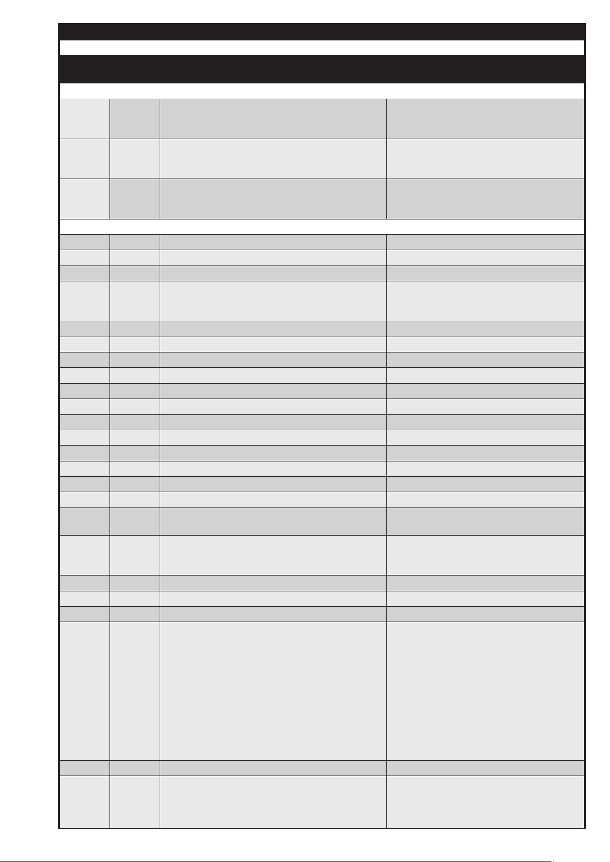
10 Error overview
MPA 51xx
Error
ID
Internal
error
Error description Possible cause of the error
10.1 Errors from processor 2
F1
Display
ashes
F2
Display
ashes
F3
Display
●
No bus connection to processor 1 ? TWI bus connection blocked by an de-
fective external bus user, for example a
defective VisionBox or ....
Incorrect display ? The display AM03 (only for MPA 51) has
been connected to the MPA 51xx.
Correct: Use AM08 or AM09
Password change for access level failed. ? Incorrect password for the access level
? Unlock key has not been pressed
ashes
10.2 Error from the basic system (0x01 to 0x3F)
0x01 ● ERROR_INTERRUPT_CYCL_STATEFRAME
0x02 ● ERROR_WD_TRIGGERING
0x03 ● ERROR_WD_HARDWARE
ERROR_UNLOCKING_DENIED ? more than 5 unlockings in the last 15
0x04
minutes, remedy: Wait or carry out an Extended unlocking
0x05 ● ERROR_ROM_TEST
0x06 ● ERROR_RAM_TEST
0x07 ● ERROR_PINSHORTCIRCUIT
0x08 ● ERROR_STACK_OVERFLOW
0x09 ● ERROR_PROGRAMMING
0x0A ● ERROR_DI_VARIABLE
0x0B ● ERROR_IN_TABCONTROLERROR
0x0C ● not used
0x0D ● ERROR_CPU_TEST
0x0E ● ERROR_EEPROM_PARAMETER
0x0F ● ERROR_ADDRESS_TEST
0x10 ● not used
0x11
ERROR_UNDERVOLTAGE ? The admissible lower voltage limit was
not reached at least for a short time
ERROR_POWERFAILURE ? The supply voltage was interrupted dur-
0x12
ing startup, in the operation or during the
regular switch-o
0x13 ERROR_WD_STATUS ? The safety chain is not potential-free
0x14 ● ERROR_DI_SEGMENT_TEST
0x15 ● ERROR_SFRREGISTER_TEST
ERROR_TWI_COMMUNICATION ? A user of the TWI bus must be con-
nected to the bus or separated from the
bus while the MPA was disconnected from
the mains. Remedy: Connect or separate
a user of the TWI bus only if the MPA is
0x16
disconnected from the mains.
? Too many users are connected to the
TWI bus or EMC faults occur on the TWI
line. Remedy: Use shorter lines or reduce
the number of users
39 … 68
0x17 ● ERROR_STATEFRAME_OVERLOAD
ERROR_EXTERNAL_APPLICATION A switch-o has been activated by an ex-
0x18
Printed in Germany • Edition 02.14 • Nr. 254 722
ternal user, for example by selecting the
function "Switch-o" in the PC software of
the VisionBox
Page 41

10 Error overview
MPA 51xx
Error
ID
Internal
error
Error description Possible cause of the error
0x19 ● not used
0x1A ● ERROR_SWWD_DURING_INITIALISATION
0x1B ● ERROR_BUFFEROVERFLOW
0x1C ●
0x1D ●
ERROR_SYNCHRONISATION_DURING_INI-
TIALISATION
ERROR_PROCESSORFAILURE ? MPA is inuenced by strong EMC inter-
ferences
0x1E ● ERROR_SFRREGISTER_STATEBLOCK
... not used
10.3 Error from the extended functions (0x40 to 0x9F)
ERROR_ FANDEFAULTS ? In the curve segment, a fan default is
predened, which is smaller than the mini-
mum speed or higher than the maximum
speed of the fan (P26 or P27).
0x40
P26 (min. speed) is 500 U/min but the
speed for modulation degree 0% is set
to 480 rpm. Or P27 (max. speed) is set to
5600 rpm but the pre-aeration B should be
carried out with 5800 rpm.
ERROR_FAN_DEVIATION ? The number of pulses in the fan feed-
back is set to an incorrect value
0x41
? The fan is not suitable for the desired
speed
? The predened tolerance is too low or
the fan controller is not optimised
ERROR_FAN_NO_FEEDBACK ? The feedback line of the fan is not cor-
rectly connected or is interrupted
0x42
? The fan is blocked and does not work
? The fan is not supplied with power or is
defective
0x43 ERROR_TEST_IONISATIONINPUT
ERROR_CURVECRC16_TEST ? The curve segment was temporarily
0x44
changed, for ex. for putting the MPA into
operation, and was not correctly enabled
later
0x45 ● ERROR_INVALID_MODULATIONDEGREE ? Modulation degree is outside the limits
0x46 not used
0x47 ● ERROR_INVALID_STEPPEDMOTORTYPE ? Check stepped motor (compare P30)
ERROR_STEPPEDMOTOR_TOLERANCE_EXCEEDED
0x48
? The lines to the stepped motor are not
correctly connected or partly interrupted
? The stepped motor is charged with more
than the admissible torque, for example
due to improper mounting of the ap or
pressure impulses.
0x49
ERROR_STEPPEDMOTOR_REFERENCE_
NOT_FOUND
? see error 0x48
0x4A ERROR_STEPPEDMOTOR_NO_REACTION ? see error 0x48
ERROR_PARAMETERRECORDSTICK_NOT_
FOUND
? Parameter record activated but not
plugged in the MPA
? Stick defective
? Duration of the standard mode (P70) is
0x4b
higher than 23 h 59 min and the continuous run is not enabled
? PWM outputs congured to analogue
operation (0..10 V or 4...20 mA) but no suitable stick is plugged in.
Printed in Germany • Edition 02.14 • Nr. 254 722
40 … 68
Page 42
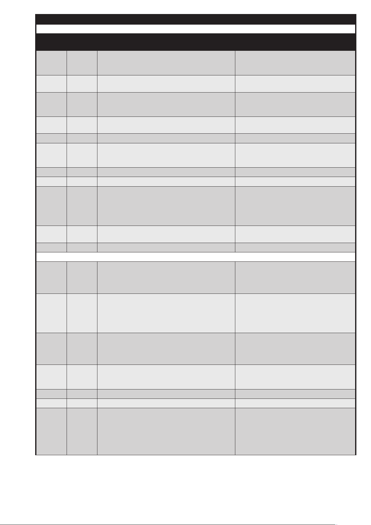
10 Error overview
MPA 51xx
Error
ID
Internal
error
Error description Possible cause of the error
ERROR_PARAMETER_RECORD_STICK_
0x4C
0x4d
BLOCK_ADJUSTMENT
ERROR_PARAMETER_RECORD_STICK_INCORRECT_PASSWORD
ERROR_PARAMETER_RECORD_STICK_
0x4E
0x4F
NO_CONTINUOUS_RUN
ERROR_PARAMETER_RECORD_STICK_
TYPE
0x50 ● ERROR_FEEDBACK_ADDITION_INCORRECT
ERROR_ADDITION_INVALID_DELAY ? Parameter P52 or P53 are set to an
0x51
0x52 not used
0x53 ERROR_LACKOFGAS_GDWVPS
ERROR_PWM_CALIBRATION_VALUES ? The EEPROM was changed or deleted
0x54 ●
? A parameter could not be copied from
the stick, for ex. because the variable lim-
its in the MPA were conned.
? The entered password is not suitable for
this stick
? Duration of the standard mode (P70) is
higher than 23 h 59 min and the continuous run is not enabled
? The stick does not t with the type of au-
tomatic burner control
invalid value because the concerned state
(P50 or P51) cannot have the set duration
when programming the parameter record
stick
? Parameter record stick defective
0x55 ●
ERROR_PARAMETER_RECORD_STICK_
CRC_DATA
... not used
10.4 Error from the application (from 0xA0)
ERROR_STATE_DURATION_TOO_LONG
0xA0
(Error fan and/or stepped motor)
ERROR_FAN_STARTUP
(Error fan and/or stepped motor)
0xA1
ERROR_SAFETY_CHAIN_OPEN ? The safety chain has been opened or is
0xA2
ERROR_PARAMETER_RECORD_STICK_
0xA3
NO_PASSWORD
0xA4 ● ERROR_FEEDBACK_V1_INCORRECT
0xA5 ● ERROR_FEEDBACK_V2_INCORRECT
ERROR_EXTERNAL_LIGHT ? Earth connection to an ionisation elec-
0xA6
? Parameter record stick defective
? in the state 3, 16 and 23: The fan and/or
the stepped motor cannot reach its nominal value within the expected time period
? other states: Internal error
? in the state 3, 16 and 23: The fan and/or
the stepped motor cannot reach its nominal value within the expected time period
? other states: Internal error
not closed
? The wires of the safety chain are interrupted
? The values in the MPA and in the parameter record stick are dierent. The requested password was not entered (timeout).
trode
? Gas ows out and is burned for ex. by
neighbouring burners
? Connected ame detector detects ex-
ternal light
41 … 68
Printed in Germany • Edition 02.14 • Nr. 254 722
Page 43

10 Error overview
MPA 51xx
Error
ID
Internal
error
Error description Possible cause of the error
ERROR_NO_FLAME_DURING_SZA ? Ionisation electrode incorrectly set
0xA7
ERROR_FLAME_GONE_OUT_DURING_OPERATION
0xA8
0xA9
ERROR_FLAME_GONE_OUT_DURING_STABILISATION
ERROR_IDLESTATECONTROL_LDW ? The air pressure detector is defective
0xAA
ERROR_NO_AIR_PRESSURE ? the air pressure detector is incorrectly
0xAB
0xAC ● ERROR_FEEDBACK_IGNITION_INCORRECT
0xAD ERROR_LACKOFGAS_GDWMIN
0xAE ERROR_VPS_V1_LEAKING
0xAF ERROR_VPS_V2_LEAKING
0xB0 ● ERROR_TESTCIRCUIT_EXTENSION
... not used
? Ignition electrodes incorrectly set
? Insulated lines of the ignition electrodes
or the ionisation electrode defective
? Pneumatic composite incorrectly set /
Incorrect gas type
? Gas valves do not open the gas ow
? Incorrect conguration of the curve
points
? Connected ame detector (UV, ...)
detects light or is defective
? Lines of mains connection on the MPA
exchanged ("N" and "L1")
? Gas supply or pneumatic composite
are not set/suitable for high capacities
? Flame body defective
? Connected ame detector (UV, ...)
detects no light or is defective
? see 0xA8, the problem occurs earlier.
? There is an air pressure during the idle
state control, for ex. due to an air ow from
the exhaust line,...
? The threshold value of the air pressure
detector is set to an incorrect value
connected or defective
? the fan does not work
? the threshold value of the air pressure
detector is set to an incorrect value
Printed in Germany • Edition 02.14 • Nr. 254 722
42 … 68
Page 44
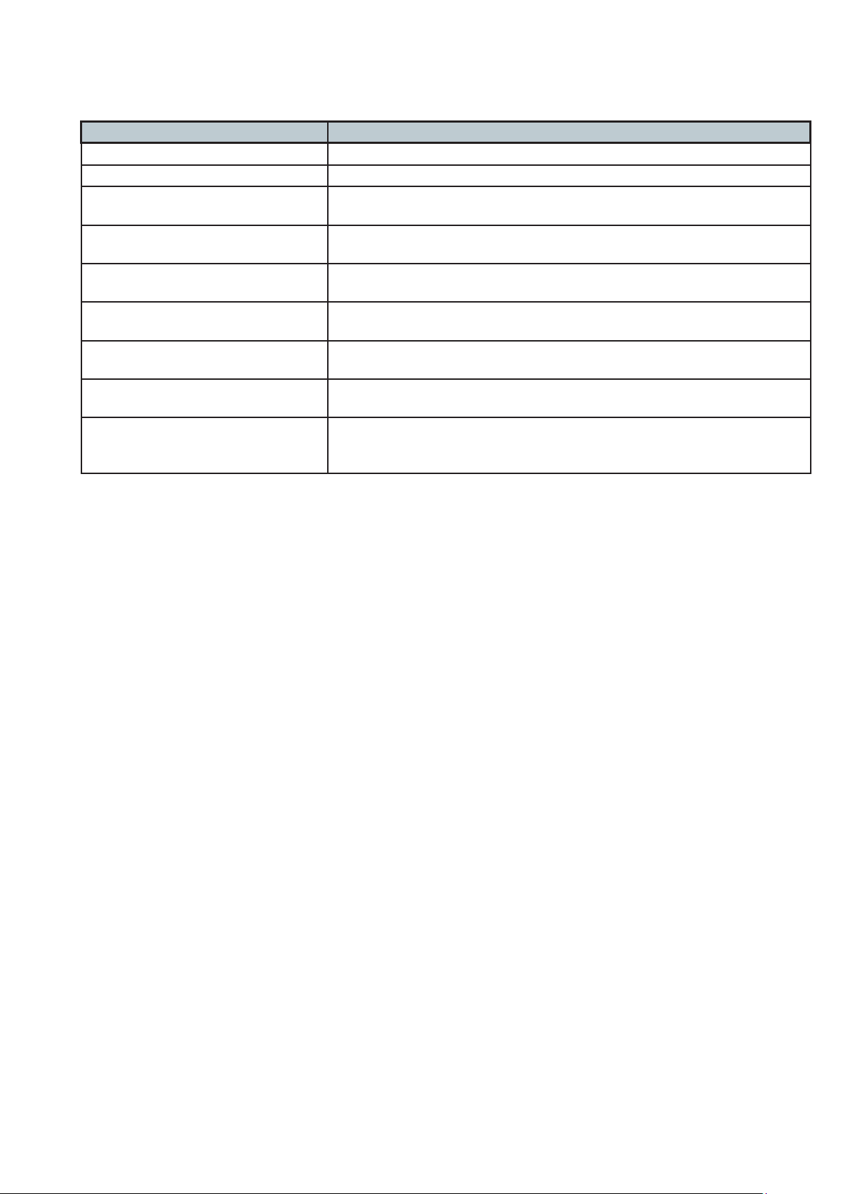
11 Display unit
11.1 Overview display modes
Mode Active
Operational status display in normal operation if no error is active
Error display if the automatic burner control is in the fault switch-o phase
Info display by pressing the key combination
(+ and ↵) in state 1 or 35
Service display by pressing the key combination
(- and ↵) in state 1 or 35
Display of the error memory by pressing the key combination
(+ and ←) in state 1 or 35
Parameterising display by pressing the key combination
(↵ and ←) in state 1 or 35
Reset display by pressing the key combination
(- and ←) in the operational status display
Password entry
if a new parameter record is to be copied
Parameter record stick
Flashing display
Option 1: Request to conrm the access level change
Option 2: Keep the unlock key depressed for more than 5 s to restart the
MPA
43 … 68
Printed in Germany • Edition 02.14 • Nr. 254 722
Page 45
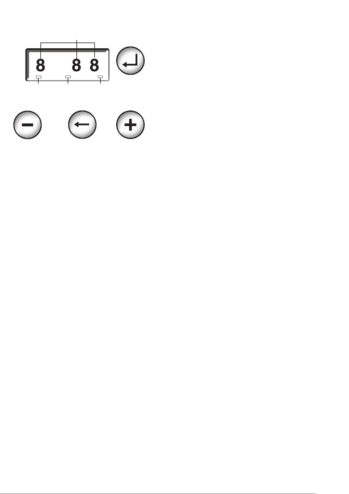
11.2 Key assignment MPA 5111 and MPA 5112
Characters
blue
Heat
request
blue
Flame
yellow
Fault
red
Printed in Germany • Edition 02.14 • Nr. 254 722
44 … 68
Page 46

11.4 Operational status display MPA5111
Display of the individual
process states
45 … 68
Printed in Germany • Edition 02.14 • Nr. 254 722
Page 47
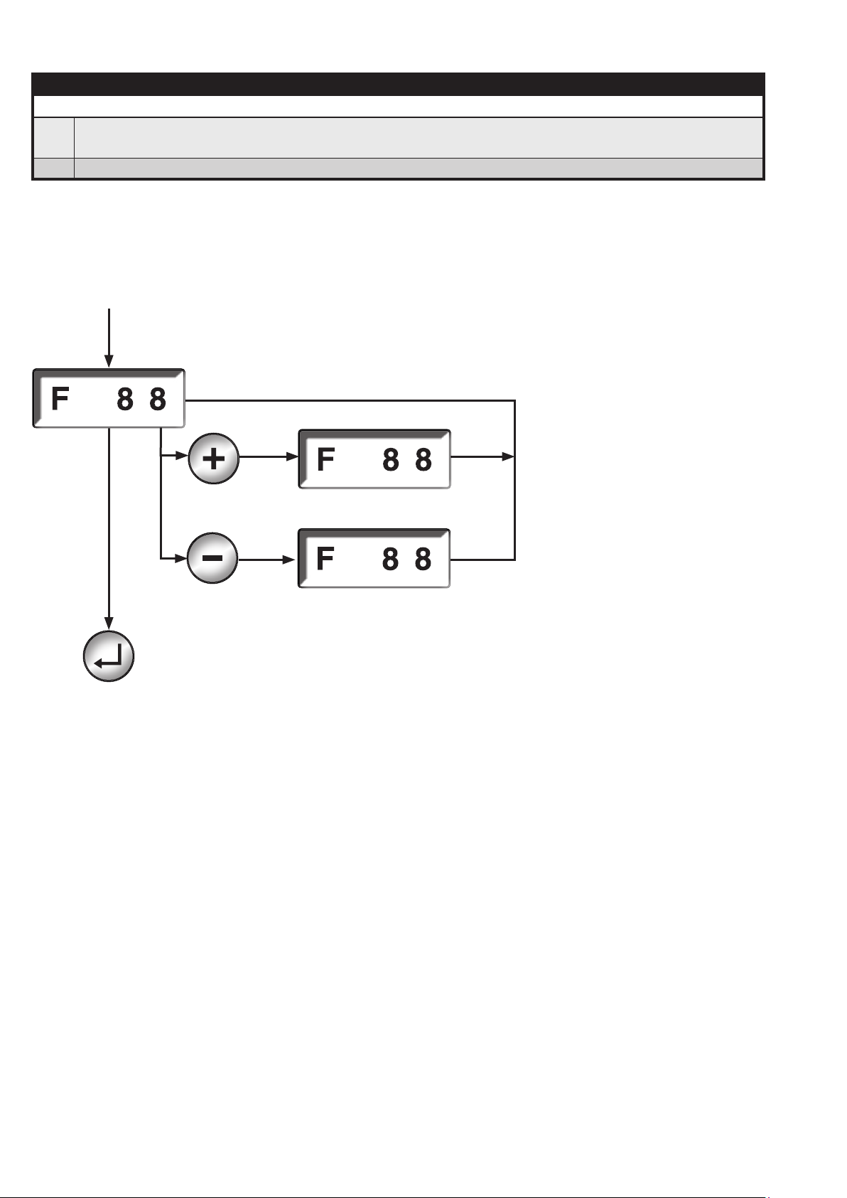
11.6 Error display
Error display
An error message is automatically displayed as soon as the automatic system goes to the fault lock
▶
system.
▶ The error that has occurred last is displayed.
Automatic activation
if a fault is active
As long as the Plus key is
kept depressed, the state
number is displayed
Unlock
As long as the Minus key
is kept depressed, the
additional error message is
displayed
Printed in Germany • Edition 02.14 • Nr. 254 722
46 … 68
Page 48
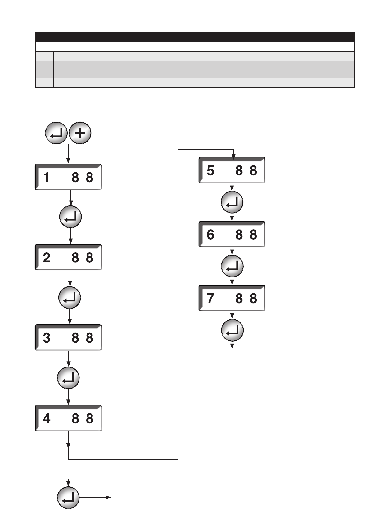
11.7 Information display
Info display
▶ The info display is activated out of the operational status display.
Using the info display, information on the current counter reading such as
▶
start counter and permanent runtime meter can be called.
▶ This operating mode is left after a timeout of 20 s if no key is pressed within this time period.
Activation of the info display
by simultaneous pressing of
the keys
Display of the
quality
of the ionisation
current
Display of the fth
place before the
decimal point (1) on
the permanent run
time meter
Display of the fth
place before the
decimal point (1)
on the permanent
start counter
Display of the fth
place before the
decimal point (100)
on the permanent
start counter
Display of the fth
place before the
decimal point (100)
on the permanent run
time meter
Display of the fth
place before the
decimal point (10000)
on the permanent run
time meter
Back to the opera-
tional status display
47 … 68
from each info display state
Printed in Germany • Edition 02.14 • Nr. 254 722
Display of the fth
place before the decimal point (10000) on
the permanent start
counter
Switches to the
operational status
display
Page 49
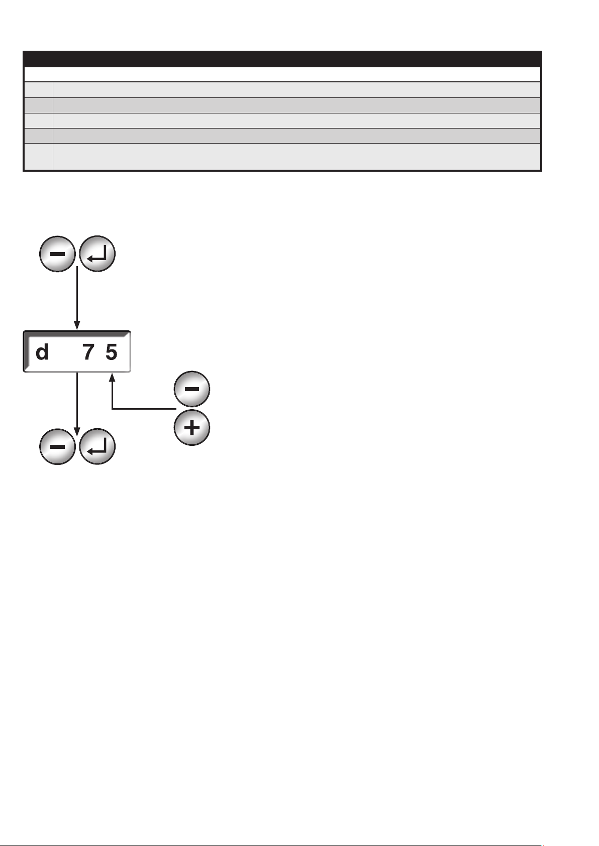
11.8 Service display
Service display
▶ The service display is activated out of the operational status display.
▶ The service display can only be activated in the burner mode.
▶ A heat request must be active on the temperature controller input.
▶ Power setting by means of the ± keys
In this mode, the device does not react to the power setting signal of the inputs Power [+] and
!!
Power [-]
Activation of the service display:
press the keys simultaneously
back to the
operational status display
set modulation percentage
Reduces the power
Increases the power
Printed in Germany • Edition 02.14 • Nr. 254 722
48 … 68
Page 50
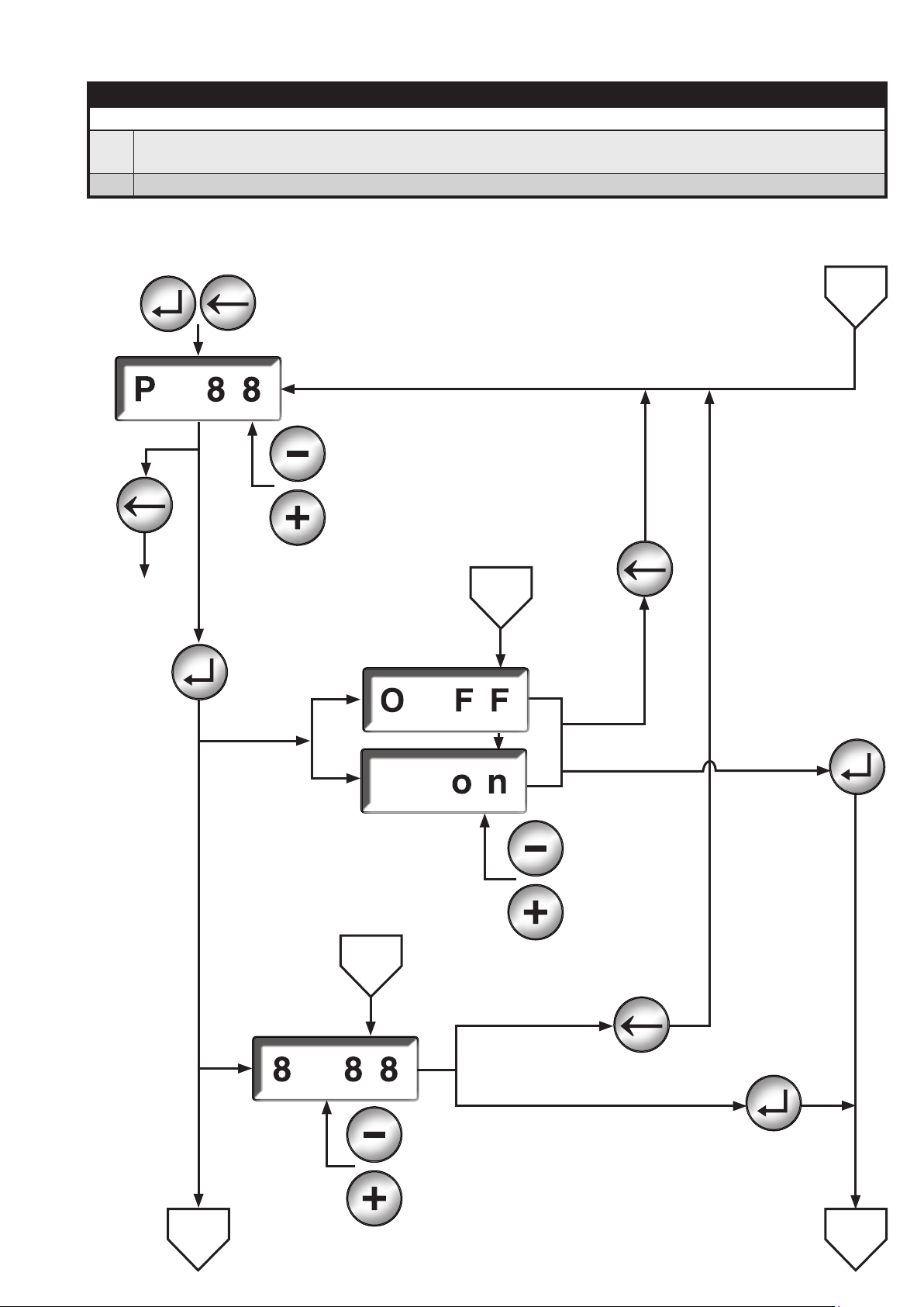
11.9 Parameterisation display
Parameterisation display
The parameterisation display can only be activated when the standby mode on the operational
▶
state indicator is active.
▶ The parameters which cannot be changed due to the access level are only displayed.
Switches to the
operational
status display
Conrm the param-
eter selection
Value equal to 0
Parameter type
U1
Activation of the parameterisation display by
simultaneous pressing of the keys
Previous parameter
Next parameter
5
Action
cancel
3,4
Saves the value
49 … 68
Printed in Germany • Edition 02.14 • Nr. 254 722
Value equal to 1
Parameter type U8
1
Reduces the value
Increases the value
5
Cancel the action
Saves the value
Reduces the value
Increases the value
2
Page 51
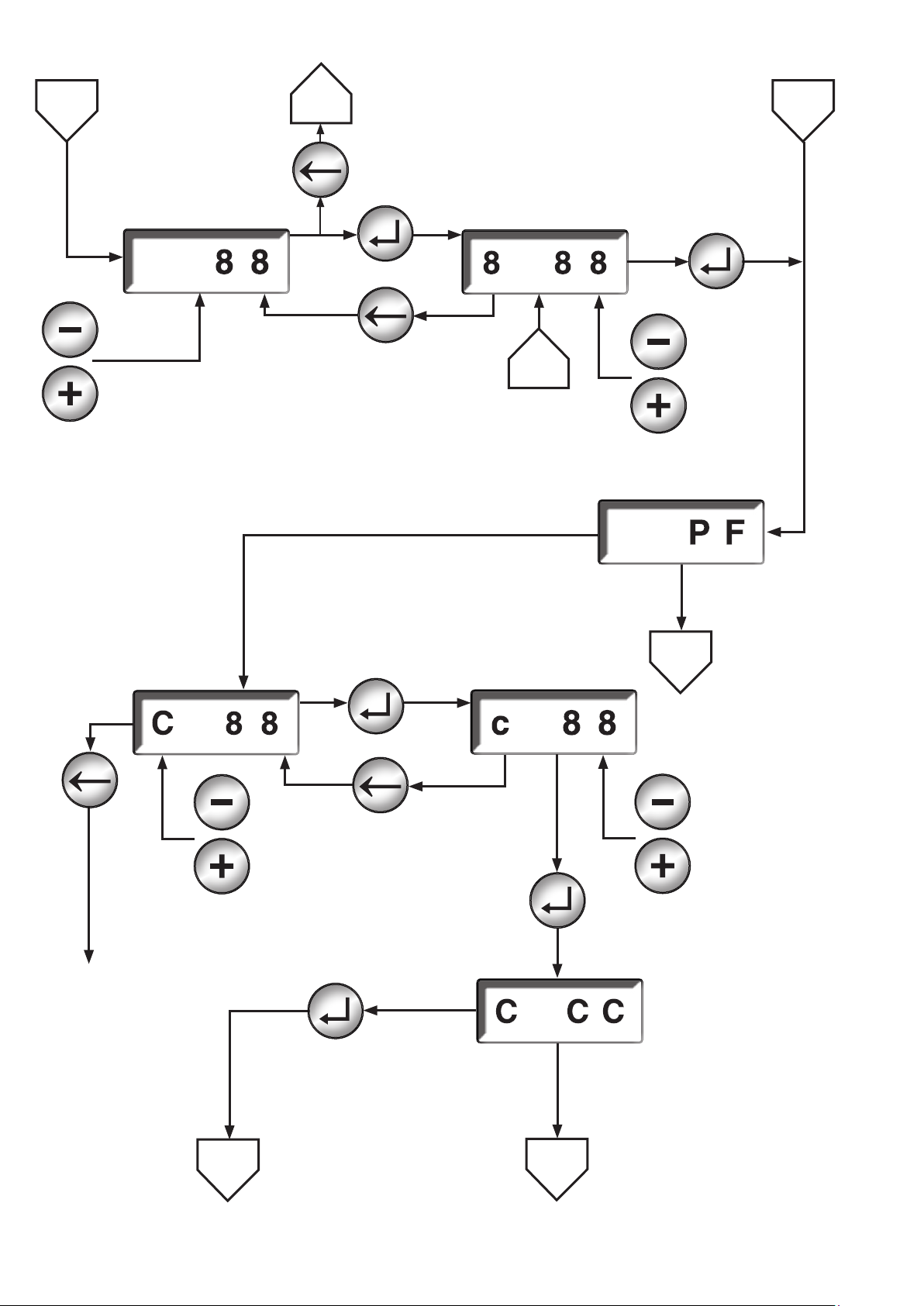
11.9 Parameterisation display
1
3
2
cancel
Parameter type U16
Set the thousands
Value
reduction
Value
increase
Set the ones
conrmation
cancel
5
conrmation
Value
reduction
Value
increase
Value in P1
correctly saved
Code input
High Byte
Switches to
the
operational
status display
Value
reduction
Value
increase
conrmation
cancel
conrmation
Code input
Low Byte
4
Value
reduction
Value
increase
conrmation
Flashing display
As long as the the level
change is conrmed by
pressing the reset key
5
back to the corresponding parameters
5
Incorrect password,
display ashes showing CCC
for 1 s orafter 30 s elapsed
without passward entry
Printed in Germany • Edition 02.14 • Nr. 254 722
50 … 68
Page 52
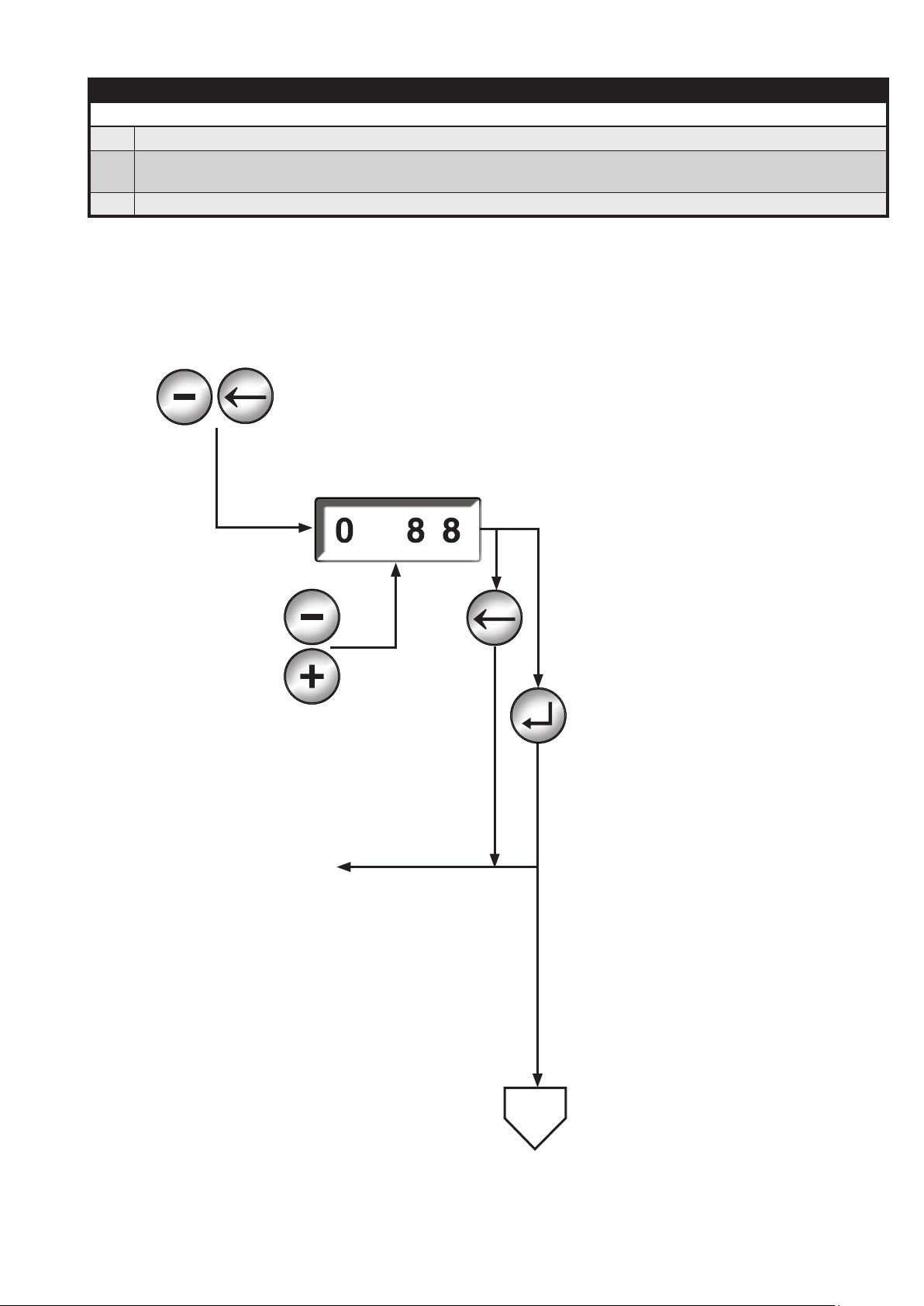
11.10 Reset display
Reset display
▶ The reset display is activated out of the operational status display.
The error memory, the access levels, resettable runtime meter and start counter can be reset by
▶
means of the reset display.
▶ This operating mode is left after a timeout of 20 s if no key is pressed within this time period.
Activation of the reset display by simultaneous pressing of the keys
previous
Parameter
next
Parameter
Back to the operational
status display
Cancel the action
Action 0,1,2,3
Action to be carried out:
0 deletes the error memory
1 resets the access level
2 deletes the resettable runtime
meter
3 deletes the resettable start
counter
4 Change password for SERVICE
level
5 Change password for OEM
level
Action 4,5
51 … 68
1
Printed in Germany • Edition 02.14 • Nr. 254 722
Page 53
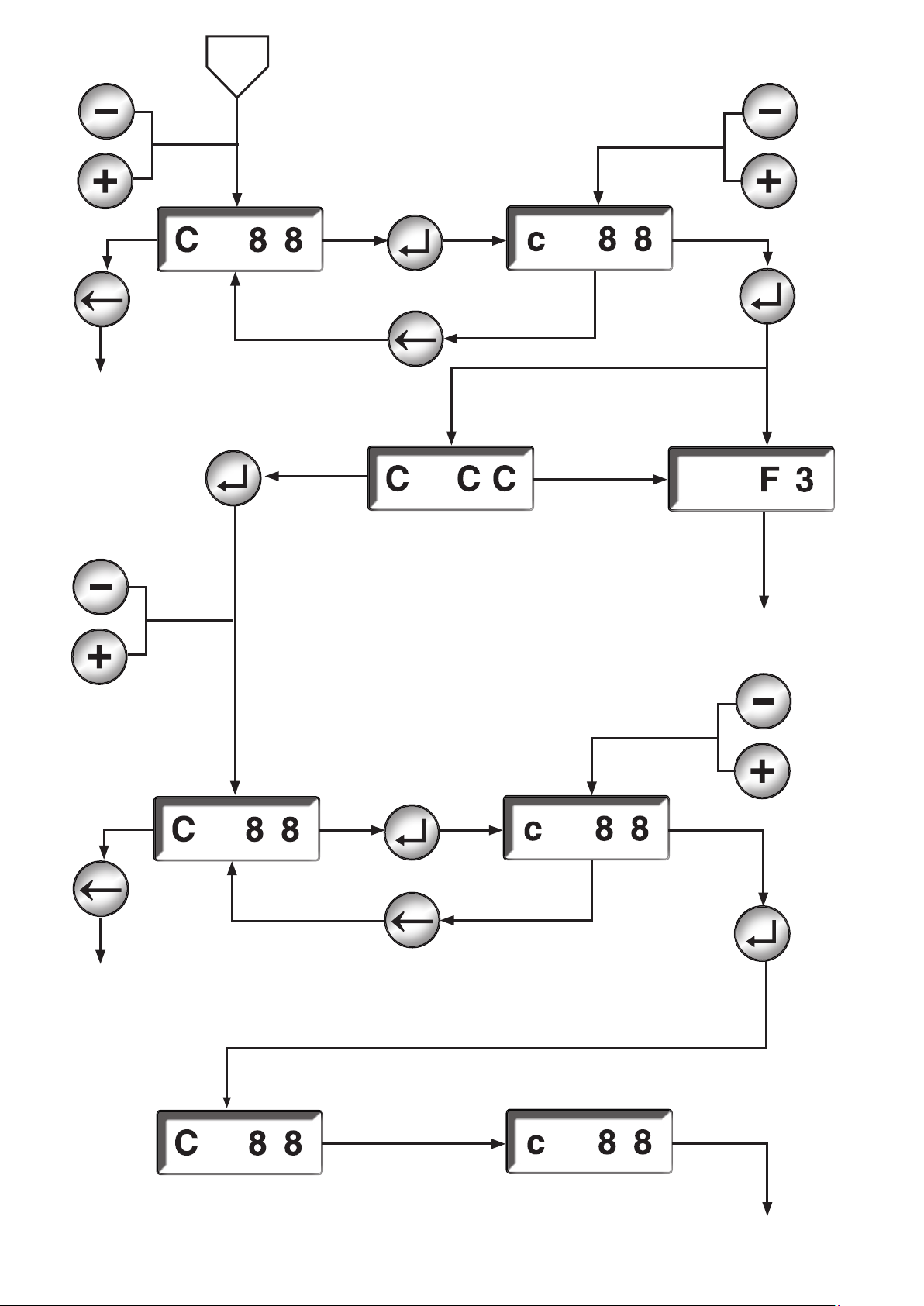
Value
reduction
Value increase
1
Value
reduction
conrmation
Value increase
conrmation
Switches to the
operation display
Value
reduction
Value increase
cancel
Correct password
Flashing display until the level
change is conrmed by means of
the reset key
Code input
New password
High byte
conrmation
30 s elapsed
without level
switching
conrmation
Incorrect password
Error,
ashing display
for 5 s
Back to
operation display
Value reduction
Code input
New password
Low byte
Value increase
Switches to the
operational status
display
Flashing display for 3 s
Code indication
New password
High byte
cancel
conrmation
Code indication
New password
Low byte
Flashing display for 3 s
Back to the operational
status display
Printed in Germany • Edition 02.14 • Nr. 254 722
52 … 68
Page 54
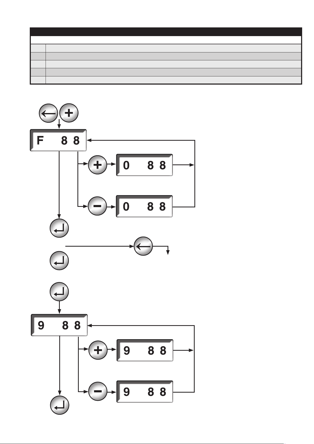
11.11 Error memory display
Display of the error memory
▶ The display of the error memory is used to call the last ten errors.
▶ The error that has occurred last is displayed.
▶ The error memory display is activated out of the operational status display.
▶ This error memory display is left after a timeout of 20 s if no key is pressed within this time period.
▶ The error that has occurred last is displayed.
last error occurred
As long as the Plus key is kept depressed, the state number is displayed
...
As long as the Minus key is kept depressed, the additional error message is
displayed
if the key is pressed, always the previous error is displayed
from each error display
state
Switches to the
operational status
display
As long as the Plus key is kept depressed, the state number is displayed
rst error of the last ten errors
53 … 68
Back to the operational status display
Printed in Germany • Edition 02.14 • Nr. 254 722
As long as the Minus key is kept depressed, the additional error message
is displayed
Page 55
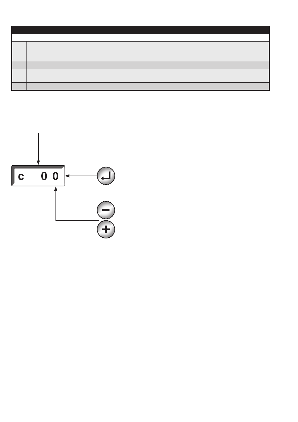
11.12 Password entry parameter record stick
Password input for parameter stick
If the parameter values of the plugged-in parameter stick do not comply with the stored parameter
▶
values of the automatic system, a password must be entered before starting the automatic system.
Then, the parameter values are copied.
▶ After conrmation the automatic gas burner performs a restart.
If the password is not correctly entered, the automatic system switches, depending on the anti-
▶
oscillation counter, to the error status or returns to the password entry.
▶ When the password entry is correct, the automatic system is restarted.
Automatic change to the
Parameter stick - password display during start process
c ashes
Code input
conrmation
then the system is restarted
Reduces the value
Increases the value
Printed in Germany • Edition 02.14 • Nr. 254 722
54 … 68
Page 56

12 VisionBox
The VisionBox is used to have access to the MPA via a PC.
See VisionBox
55 … 68
Printed in Germany • Edition 02.14 • Nr. 254 722
Page 57

13 Flame detector
The following ame detectors are
approved by DUNGS and can be
recommended for use in connection
with the MPA51xx:
Manufacturer Designation Type Output signal Reaction
time
- Ionisation
Ionisation Ionisation < 1 s Yes
electrode
BST solutions
DUNGS
BST solutions
DUNGS
KLC 1000
FLW 20
KLC 2000
FLW 10
UV tube Ionisation (1 s + 0.5 s) =
< 1.5 s
Flicker detector with
Ionisation (1 s + 0.5 s) =
< 1.5 s
frequency
analysis
DUNGS has the following requirements to ame detectors used with
the MPA51xx:
4. Under these conditions, the simu-
lation circuit in the ame detector
must reach at least a direct current 3 µA.
1. Approval and certication by the
respective bodies (DVGW, DIN
Certco,...) must be ideally provided.
An independent prove about the
compliance with the respective
demands of the DIN EN298 is
required.
2. The ionisation behaviour of a
ame must be simulated (rectier
eect)
3. The following values are active on
the ionisation input and output
230 VAC +10 % -15 %
The internal resistance of the
MPA is approx 1 MΩ. For safety
reasons, the ame sensor must
work properly also with an internal
resistance of 360 kΩ.
If an alternating current with a DC
component is simulated, the DC
component should reach at least
25%.
The current can be derived to N,
PE or returned to N on the MPA.
5. The supply voltage for the ame
detector must be tapped o at the
output ION_PWR of the MPA51xx
(230 VAC, max. 1 A).
6. The reaction times must be observed!
Total reaction time = reaction time
MPA + reaction time ame detec-
tor
The reaction time of the MPA is < 1 s
7. The EMC regulations must be
observed (EN 298). The entire
system must not represent inadmissible emissions.
For a good ame detection the ame
signal has to be considered during
conguration of the burner.
The LED of the ame on the display
must not be ashing and the dis-
played signal in the VisionBox application must have more than 40 digits.
Certicate Continuous
operation
Yes No
Yes No
8. The MPA51xx is not decoupled.
The polarity of the MPA and the
ame detector must be strictly
observed.
9. Prior to use a ame sensor which
is not included in the list, please
contact DUNGS. DUNGS cannot
be held liable if the ame detector
and the automatic burner control
do not work orderly together.
Especially if the electromagnetic
behaviour is not according to the
regulations or if the time dependent behaviour is not correct.
Printed in Germany • Edition 02.14 • Nr. 254 722
56 … 68
Page 58
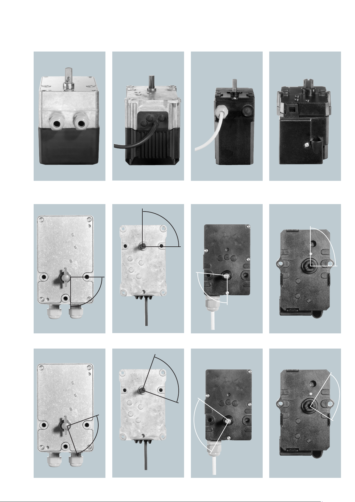
14 Stepped motor
14.1 Overview of the possible stepped motor types
SAD 15 SAD 1.2 WG SAD 1.5 SAD 1.2
SAD 3.0 WG SAD 3.0 (IP 40)
SAD 10 WG
*1
14.2 Reference point "Standard"
The rotation ranges are indicated
90°
0°
14.3 Reference point "Exchanged"
0°
0°
90°
90° =
93,37°
90°
0°
90°
57 … 68
0°
90°
Printed in Germany • Edition 02.14 • Nr. 254 722
1*
this version is not yet available
90°
0°
0°
0°
90° =
93,37°
Page 59
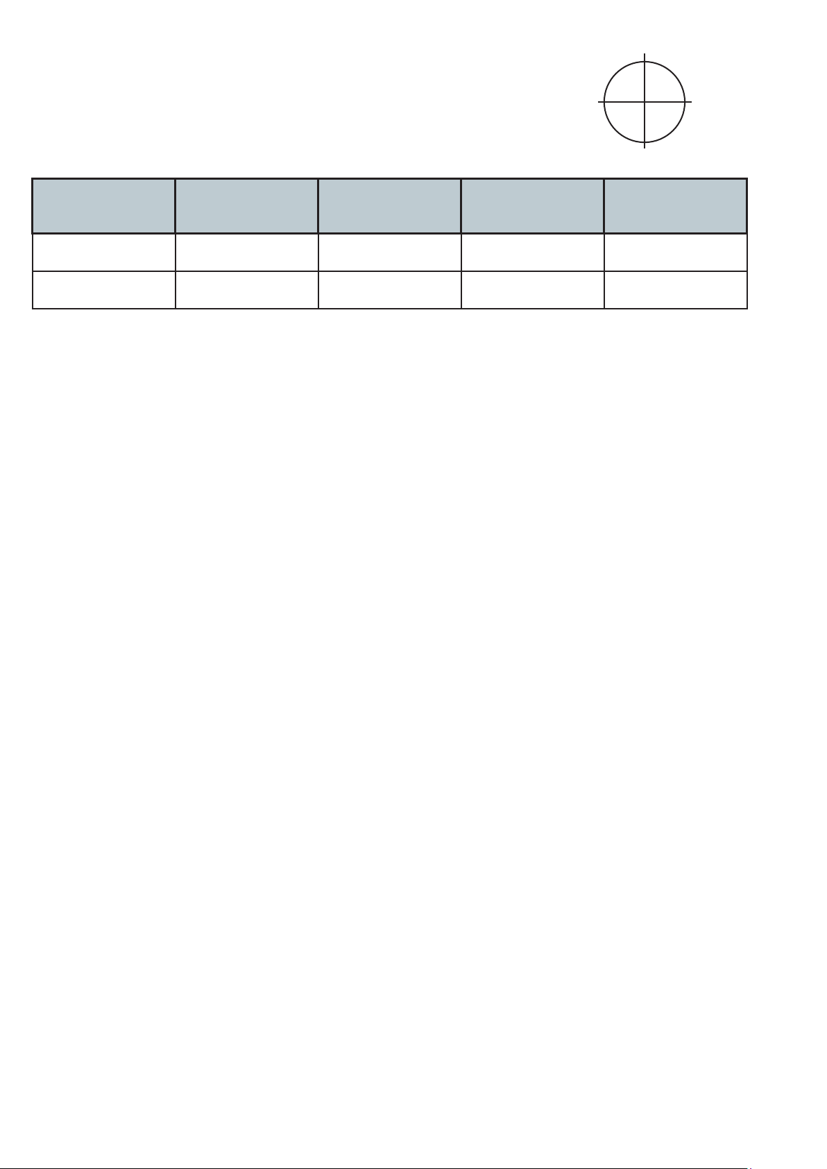
14.4 Mathematical angle positions
The mathematical angle position is
indicated in the view from the bottom
on the driven shaft as shown in the
pictures above.
The mathematical angle position
0° / 90° correspond to:
of the stepped motor position 0° or
90° for the respective stepped motor type is indicated in the following
table:
180°
90°
0°
(360°)
270°
SAD 15 SAD 1.2 WG
Reference point
270° / 0° 90° / 0° 270° / 166,63° 90° / 0°
"Standard":
Reference point
19° / 289° 81,5° / 341,5° 156,92° /
"Exchanged":
*1 : this version is not yet available
Attention!
All stepped motors must be
equipped with two mechanical stops.
• Lower mechanical stop between -7°
and -10°
• Upper mechanical stop between
92° and 95° or
upper mechanical stop between
95,5° and 98,5° for SAD1.5 and
SAD3.0 (IP 40)
The absolute stop positions depend
on the stepped motor and the selected reference point (see table).
SAD 3.0 WG
SAD 10 WG
SAD 1.5
SAD 3.0
*1
(IP 40)
SAD 0.6
SAD 1.2
341° / 71°
250,29°
Printed in Germany • Edition 02.14 • Nr. 254 722
58 … 68
Page 60
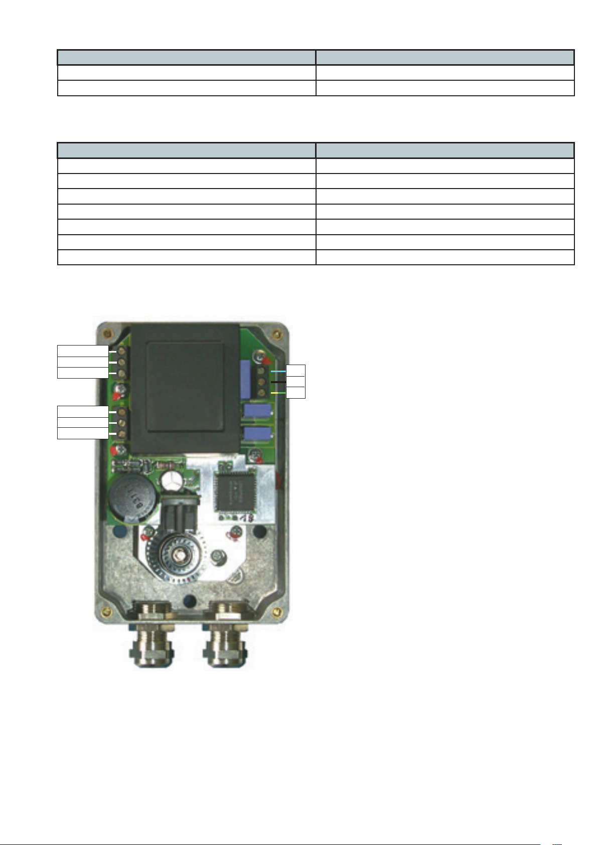
14.5 Wiring diagram SAD15
P1
P3
P2
N
L
PE
EA SA 1
EB SB 2
OK WD 3
GND 4
AA MA 5
AB MB 6
Power supply
PIN designation in the SAD 15 230 V mains power supply or MPA output 6
L L1
N N
Signal lines SAD15
PIN designation in the SAD 15 230 V mains power supply or MPA output 6
1 6
2 5
3 not used
4 2
5 4
6 3
not used 1
Connection SAD15
59 … 68
Printed in Germany • Edition 02.14 • Nr. 254 722
Page 61

14.6 Power supply of the stepped motors
Stepped motor 230 V (L1)
Mains power supply
24 V by means of a separate power supply unit
24 V via MPA5111
SAD 1.2 - X (> 7W) X
SAD 1.2 WG - X (> 7.5W) X
SAD 1.5 - X (> 7W) X
SAD 3.0 (IP40) X - SAD 3.0 WG - X (> 10W) X
SAD 10 WG *1 - X (> 10W) ?
SAD 15 X - -
*1
this version is not yet available
Printed in Germany • Edition 02.14 • Nr. 254 722
60 … 68
Page 62

61 … 68
Printed in Germany • Edition 02.14 • Nr. 254 722
Page 63
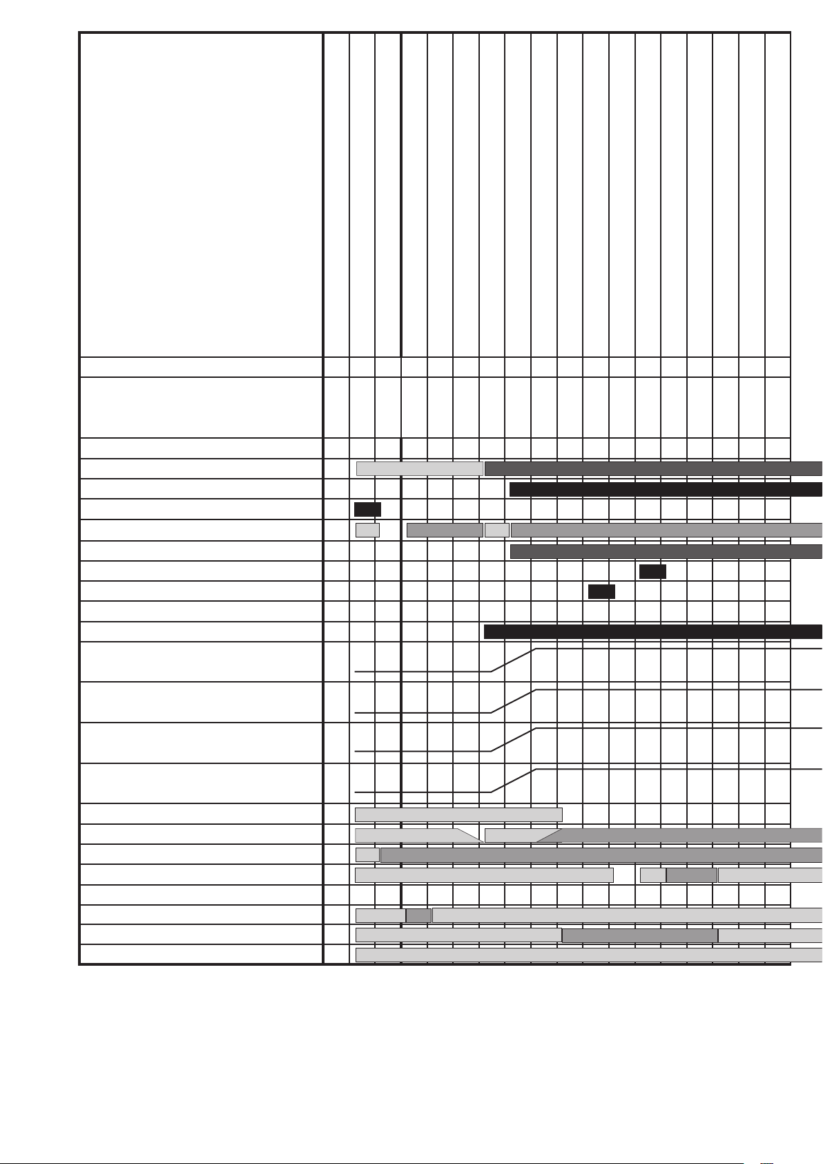
15 Time diagram
MPA51xx
Parameter
Time
State number
Safety chain
Watchdog
Alarm
Temperature controller
Additional valve *4
V1
V2
Ignition
Fan relay
PWM1 (fan)
by means of an extended module
General version
Y1 Y3
Y2 Y1
Y3 Y2
Viessmann version
Error
Waiting for heat request
Waiting for parameter record stick adjustment
Idle state control: Fan/stepped motor
Idle state control LDW (air pressure switch)
Watchdog loading phase
Startup phase: Fan/stepped motor
Waiting for air pressure
VPS A: Decision
VPS A : Emptying the area between the valves
VPS A: Test time V1
VPS A: Filling the area between the valves
VPA A: Gas pressure detection
P40 P42 P43 P44 P45 P60
0...
0...
max. 3 m in
max. 2 m in
max. 2 m in
3 s
max. 2 m in
max. 3 0 s
0.1 s
1...3 s
1...240 s
1...3 s
0.1 s
0 1 2 3 4 5 6 7 8 9 10 11 12 13 14
*2a
*2b
VPS A: Test time V2
Pre-aeration A
1...240 s
0...1 h
PWM2 (for ex. analogue 0...10 V)
PWM3 (for ex. analogue 4... 20 mA)
Stepped motor
Flame (ionisation)
LDW *1
GDW min.
GDW VPS *5
Parameter record stick active
Parameter VPS Startup
Parameter VPS Regular switch-o
*1) The monitoring of the LDW depends on
the operating mode set in P14.
*2) Analogue and fan capacities as well as fan
speed can be set by means of curves.
a) Special modulation point: OFF
b) Special modulation point: Pre-aeration A
c) Special modulation point: Pre-aeration B
d) Special modulation point: Ignition position
● *2a
● *2a
● *2a
●
e) Special modulation point: STA
f) Special modulation point: Stabilisation A
g)
Special modulation point: Stabilisation B
h) Parameter P67: Start modulation degree
Standard mode
i) Parameter P81: Regular switch-o: Power
during transition
j) Special modulation point: Post-aeration
*2b
*2b
*2b
*3) In the waiting program state, the rst waiting time is 2 minutes, then 5 minutes, then 1
hour and afterwards a time period which can
be set by means of a parameter between 1
minute and 50 hours. If the set time period is
smaller than the rst three intervals, these are
also reduced. Another parameter indicates
whether a fault switch-o is allowed and, if
yes, how many restart attempts are to be
carried out until the automatic burner control
Printed in Germany • Edition 02.14 • Nr. 254 722
62 … 68
Page 64
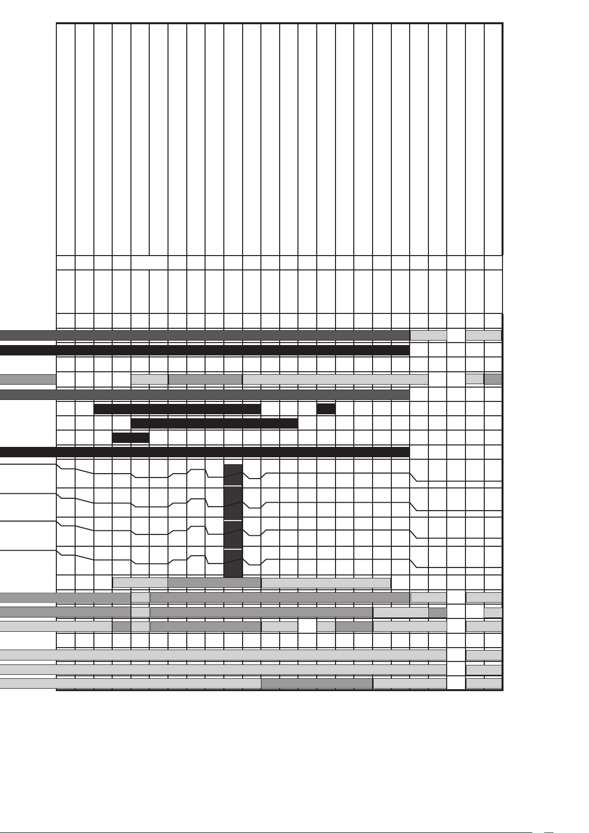
Pre-aeration B
Ignition position
Gas detection GDWVPS
Pre-ignition
SZA ignition
SZA - Flame detection
Stabilisation ame A
Stabilisation ame B
Changeover to the standard mode
Standard mode
Changeover after regular switch-o
VPS B: Decision
VPS B : Emptying the area between the valves
VPS B: Test time V1
VPS B: Filling the area between the valves
VPA B: Gas pressure detection
VPS B: Test time V2
Follow-up time
Post-aeration
Restart protection
Waiting for heat request
P61 P62 P63 P64 P65 P66 P70 P80 P41 P42 P43 P44 P45 P82 P83 P84 *3
0...1 h
max. 2 m in
0...1 h
0...1 min.
0.5.. .9, 4 s
0.5 s
1...200 s
1...200 s
max. 2 m in.
0...
1...30 s
0.1 s
1...3 s
1...240 s
1...3 s
0.1 s
1...240 s
1...60 s
0...1 h
0...1 h
0...
15 16 17 18 19 20 21 22 23 24 25 26 27 28 29 30 31 32 33 34 1 35 36
*2a
*2c *2d *2e *2f *2g *2h *2i *2j
*2a
*2c *2d *2e *2f *2g *2h *2i *2j
*2a
*2c *2d *2e *2f *2g *2h *2i *2j
*2a
Lack of gas GDWMIN
0...
Waiting program
x min.
63 … 68
*2c *2d *2e *2f *2g *2h *2i *2j
*6
goes to the fault switch-o. The waiting program state is triggered by a lack of gas or an
open safety chain.
*5) The GDW VPS is monitored during the
valve test. Additionally, the parameter P46
can dene whether the minimum pressure
monitoring via GDWVPS during operation
*4) The start help valve can be switched on
between state 17 and state 25 is active or not.
and o at any time (parameter). However it
must be activated with the beginning of the
state "Waiting for gas pressure" at the earli-
Printed in Germany • Edition 02.14 • Nr. 254 722
est and during the valve test after a regular
*6) The ame is detected here and must be
generated in this state at the latest.
switch-o at the latest.
Page 65

Appendix A
Versions and variants
Variant Version SAP device SAP SW P1
Stick type
for VisionBox
MPA5111 V1.0 251446 D 251547 _ 51 1
V1.1 251446 E 251547 A 51 2
Changes from V1.0 to V1.1
1. The V1.1 version corresponds
to VDE EN60335-1 section 30 of
2007.
2. The passwords for OEM and
SERVICE levels can be changed
now.
3. Preparations for connection of
Probus modules.
4. Simplications for parameter
changing procedure.
Printed in Germany • Edition 02.14 • Nr. 254 722
64 … 68
Page 66
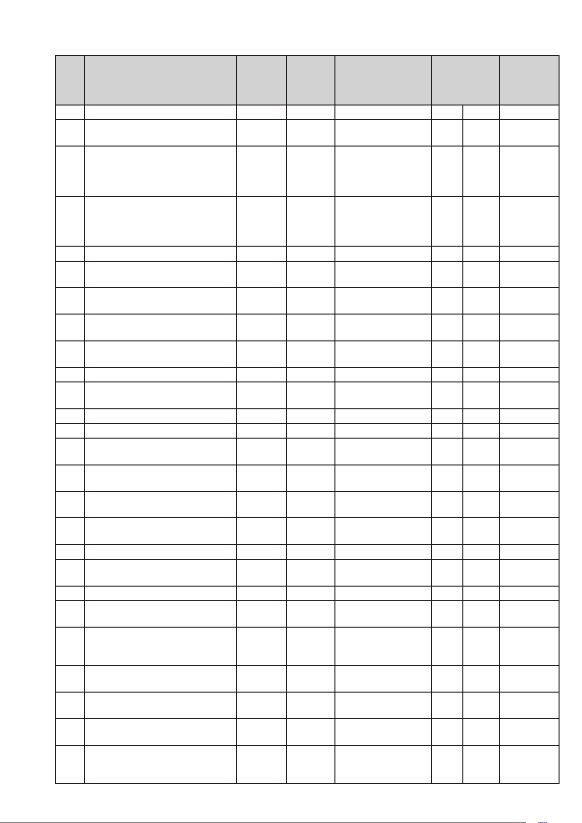
Appendix B
Parameter overview
Name DUNGS
Aus-
Einheit Bedeutung
Einstellwerte
Min Max
Zugris-
ebene
lieferung
Para-
meter
10 PARAMETER_STICK_AKTIV AUS Parameterstick: aktiv OEM
11 ANZAHL_WIEDERANLAUFVER-
SUCHE
12 ANZAHL_WIEDERANLAUFVER-
SUCHE_NACH_FEHLER_
KEINE_FLAMME_WAEHREND_
5 Wiederanlaufver-
suche
0 Wiederanlaufver-
suche nach fehlender Flammenbildung
0 10 OEM
0 10 OEM
SZA
13 ANZAHL_WIEDERANLAUFVER-
SUCHE_NACH_FEHLER_
FLAMMENABRISS_IM_BE-
0 Wiederanlaufver-
suche nach Flammenabriss
0 10 OEM
TRIEB
14 BETRIEBSART_LDW 0 LDW: Betriebsart 0 3 OEM
15 BETRIEBSART_TEMPERATUR-
REGLER
16 PARAMETERSATZ_KUNDEN_ID 0 Parametersatz:
3 Temperaturregler:
Betriebsart
0 255
BETREIBER
0 255 DUNGS
Kundennummer
17 PARAMETERSATZ_SATZ_ID 0 Parametersatz:
0 255 DUNGS
Nummer
18 BETRIEBSART_PWM_AUS-
GAENGE
0 Analogausgänge:
Betriebsart
0 15 SERVICE
20 GEBLAESE_REGELSCHALTER AUS Gebläse: Regelung OEM
21 GEBLAESE_RAMPE_VER-
ZOEGERUNG
1 Gebläse:
Verzögerung/Rampe
0 10 OEM
22 GEBLAESE_KP 50 Gebläse: Kp-Faktor 0 160 OEM
23 GEBLAESE_TN 50 Gebläse: Tn-Faktor 1 160 OEM
24 GEBLAESE_PULSZAHL 2 1/U Gebläse: Pulse pro
1 10 SERVICE
Umdrehung
25 GEBLAESE_ZULAESSIGE_
TOLERANZ
26 GEBLAESE_DREHZAHL_MIN 2000 U/min Gebläse: Drehzahl
500 0,01% Gebläse: zulässige
Toleranz
0 3000 OEM
1 10000 SERVICE
min.
27 GEBLAESE_DREHZAHL_MAX 10000 U/min Gebläse: Drehzahl
500 10000 SERVICE
max.
30 SCHRITTMOTOR_TYP 0 Schrittmotor: Typ 0 11 SERVICE
31 SCHRITTMOTOR_ZULAES-
SIGE_TOLERANZ
300 0,01Grad Schrittmotor: zuläs-
sige Toleranz
0 500 OEM
40 VPS_ANLAUF_AKTIV AUS VPS: aktiv im Anlauf OEM
41 VPS_ABSCHALTUNG_AKTIV AUS VPS: aktiv bei Ab-
OEM
schaltung
42 DAUER_VPS_ZWISCHEN-
RAUM_LEEREN
16 1/16 s VPS: Dauer
Zwischenraum
0 48 OEM
leeren
43 DAUER_VPS_PRUEFZEIT_V1 160 1/16 s VPS: Prüfzeit Ventil 10 9600 OEM
65 … 68
44 DAUER_VPS_ZWISCHEN-
RAUM_FUELLEN
16 1/16 s VPS: Dauer
Zwischenraum füllen
0 48 OEM
45 DAUER_VPS_PRUEFZEIT_V2 160 1/16 s VPS: Prüfzeit Ventil 20 9600 OEM
46 GDWVPS_ALS_MINUEBERWA-
CHUNG
Printed in Germany • Edition 02.14 • Nr. 254 722
AUS GDWVPS: Mind-
rucküberwachung
aktiv
OEM
Page 67
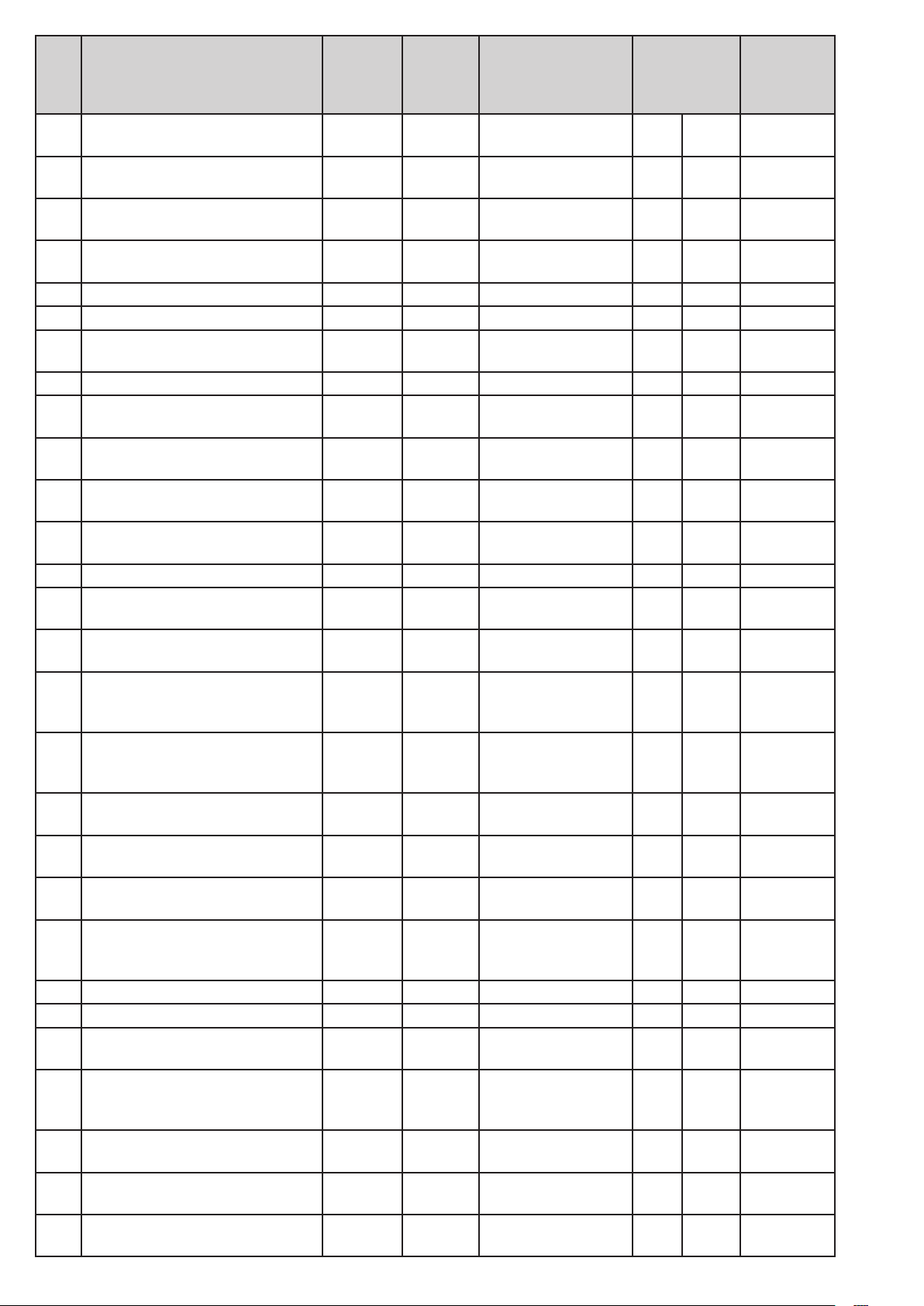
Name DUNGS
Aus-
Einheit Bedeutung
Einstellwerte
Min Max
Zugris-
ebene
lieferung
Para-
meter
50 ZUSATZVENTIL_EINSCHALT-
STATE
51 ZUSATZVENTIL_AUSSCHALT-
STATE
52 ZUSATZVENTIL_EIN-
SCHALTVERZOEGERUNG
53 ZUSATZVENTIL_AUSS-
CHALTVERZOEGERUNG
22 State Zusatzventil: Ein-
schaltstate
22 State Zusatzventil: Auss-
chaltstate
0 1/16 s Zusatzventil: Ein-
schaltverzögerung
0 1/16 s Zusatzventil: Auss-
chaltverzögerung
6 33 OEM
6 33 OEM
0 65535 OEM
0 65535 OEM
60 DAUER_VORBELUEFTUNG_A 960 1/16 s Vorbelüftungszeit A 0 65534 OEM
61 DAUER_VORBELUEFTUNG_B 0 1/16 s Vorbelüftungszeit B 0 65534 OEM
62 DAUER_GASDETEKTION_GD-
WVPS
0 1/16 s Dauer Gasdetektion
Anlauf
0 160 OEM
63 DAUER_VORZUENDUNG 4 1/16 s Vorzündzeit 2 65534 OEM
64 DAUER_SZA 16 1/16 s Sicherheitszeit
16 160 OEM
Anlauf
65 DAUER_STABILISIERUNG_
80 1/16 s Stabilisierungszeit A 0 65534 OEM
FLAMME_A
66 DAUER_STABILISIERUNG_
0 1/16 s Stabilisierungszeit B 0 65534 OEM
FLAMME_B
67 STARTMODULATIONSGRAD_
REGELBETRIEB
3000 0,01% Modulationsgrad bei
Start Regelbetrieb
0 10000 SERVICE
70 DAUER_REGELBETRIEB 1439 min Dauer Regelbetrieb 0 65535 OEM
71 MODULATIONSGRAD_NEUER_
SOLLWERT
72 ART_MODULATIONSGRADAE-
NDERUNG
73 SCHRITTWEITE_MODULA-
TIONSGRADAENDERUNG
65535 0,01% Modulationsgrad:
neuer Sollwert
1 Modulationsgrad:
Art der Änderung
100 0,01% Modulationsgrad:
Schrittweite der
0 65535
BETREIBER
0 3 SERVICE
0 10000 SERVICE
Änderung
74 INTERVALL_ANALOGWERTUE-
BERNAHME
240 1/16 s Modulationsgrad:
Intervall Analogw-
1 65535 OEM
ertübernahme
75 MODULATIONSGRAD_UNTER-
GRENZE
76 MODULATIONSGRAD_OBER-
GRENZE
80 DAUER_UEBERGANG_NACH_
REGELABSCHALTUNG
81 MODULATIONSGRAD_UEBER-
GANG_NACH_REGELAB-
0 0,01% Modulationsgrad:
Untergrenze
10000 0,01% Modulationsgrad:
Obergrenze
0 1/16 s Regelabschaltung:
Übergangszeit
3000 0,01% Modulationsgrad bei
Regelabschaltung
0 10000 SERVICE
0 10000 SERVICE
0 65534 OEM
0 10000 OEM
SCHALTUNG
82 DAUER_NACHBRENNZEIT 160 1/16 s Nachbrennzeit 9 65534 OEM
83 DAUER_NACHBELUEFTUNG 160 1/16 s Nachbelüftungszeit 0 65534 OEM
84 DAUER_WIEDEREINSCHALT-
SPERRE
90 WARTEPROGRAMM_ANZAHL_
WIEDERANLAUFVERSUCHE
80 1/16 s Wiedereinschalt-
sperrzeit
255 Anzahl Warteprogramm:
Anzahl Wiederan-
0 65534 SERVICE
0 255 SERVICE
laufversuche
91 DAUER_WARTEPROGRAMM 120 min Warteprogramm:
1 65534 SERVICE
Dauer
100 KUNDENSPEZIFISCH_OEM_0 0 Kundespezisch:
0 65535 OEM
OEM 0
101 KUNDENSPEZIFISCH_OEM_1 0 Kundespezisch:
0 65535 OEM
OEM 1
Printed in Germany • Edition 02.14 • Nr. 254 722
66 … 68
Page 68
Name DUNGS
Aus-
Einheit Bedeutung
Einstellwerte
Min Max
Zugris-
ebene
lieferung
Para-
meter
102 KUNDENSPEZIFISCH_OEM_2 0 Kundespezisch:
0 65535 OEM
OEM 2
103 KUNDENSPEZIFISCH_OEM_3 0 Kundespezisch:
0 65535 OEM
OEM 3
104 KUNDENSPEZIFISCH_OEM_4 0 Kundespezisch:
0 65535 OEM
OEM 4
105 KUNDENSPEZIFISCH_BE-
TREIBER_0
106 KUNDENSPEZIFISCH_BE-
TREIBER_1
107 KUNDENSPEZIFISCH_BE-
TREIBER_2
108 KUNDENSPEZIFISCH_BE-
TREIBER_3
109 KUNDENSPEZIFISCH_BE-
TREIBER_4
230 RESERVIERT_BETRIEBSART_
BRENNSTOFF
0 Kundespezisch:
Betreiber 0
0 Kundespezisch:
Betreiber 1
0 Kundespezisch:
Betreiber 2
0 Kundespezisch:
Betreiber 3
0 Kundespezisch:
Betreiber 4
0 Reserviert: Betrieb-
sart Brennsto
0 65535
0 65535
0 65535
0 65535
0 65535
0 255
BETREIBER
BETREIBER
BETREIBER
BETREIBER
BETREIBER
BETREIBER
240 RESERVIERT_OEM_0 0 Reserviert: OEM 0 0 65535 OEM
241 RESERVIERT_OEM_1 0 Reserviert: OEM 1 0 65535 OEM
242 RESERVIERT_OEM_2 0 Reserviert: OEM 2 0 65535 OEM
243 RESERVIERT_OEM_3 0 Reserviert: OEM 3 0 65535 OEM
244 RESERVIERT_OEM_4 0 Reserviert: OEM 4 0 65535 OEM
245 RESERVIERT_BETREIBER_0 0 Reserviert: Betreiber 00 65535
BETREIBER
246 RESERVIERT_BETREIBER_1 0 Reserviert: Betreiber 10 65535
247 RESERVIERT_BETREIBER_2 0 Reserviert: Betreiber 20 65535
248 RESERVIERT_BETREIBER_3 0 Reserviert: Betreiber 30 65535
249 RESERVIERT_BETREIBER_4 0 Reserviert: Betreiber 40 65535
BETREIBER
BETREIBER
BETREIBER
BETREIBER
67 … 68
Printed in Germany • Edition 02.14 • Nr. 254 722
Page 69

Printed in Germany • Edition 02.14 • Nr. 254 722
68 … 68
Page 70
www.dungs.com
Karl Dungs GmbH & Co. KG
Siemensstraße 6–10
D-73660 Urbach, Germany
Telefon +49(0)7181-804-0
Telefax +49(0)7181-804-166
[email protected]
www.dungs.com
 Loading...