

Page 1
DMA
Burnerparts.com
Industrial Combustion Components
Tel: 804.236.3881 Fax: 804.236.3882 E-mail: [email protected]
Motor Actuator
Installation Instructions
DMK/6
Butterfly Control Valve
Installation Instructions
DMA ACTUATOR SPECIFICATIONS
The DMA actuator drives from 0 to 90 degrees via 4-20 mA
input signal. It can move in any direction and stop anywhere
over the entire 90 degree stroke.
Electrical Rating
110-120 Vac (+10 / -15%) 50-60 Hz
Max. Power Rating
2.0 VA Holding, 5.4 VA Operating
Max. Torque Ratings
Timing Holding Operating
6 12.4 in-lb 5.3 in-lb
12 24.8 in-lb 8.9 in-lb
30 26.5 in-lb 17.7in-lb
Position Resolution
0.08mA resolution; minimum of 0.45° per step
DMK BUTTERFLY VALVE SPECIFICATIONS
The DMK/6 butterfly control valve actuates from 0 to 90
degrees in either direction; it is not a tight shut-off valve.
Input-side male thread and output-side female thread enable assembly directly to DUNGS shutoff valves.
Gases
Natural gas, propane, butane, noncorrosive gases,
and air. Suitable for up to 0.1% by volume, dry H
Max. Pressure
7 PSI (500mbar) MH194167
Max. Differential Pressure
1.5 PSI (100mbar)
2
S.
Max. Contact Rating for Auxiliary Switch
1.5 Amps at 120 Vac 50/60 Hz
Enclosure Rating
NEMA Type 1 enclosure (standard with DMA)
NEMA Type 4 enclosure avaliable (Part #D240 456)
Input Control
4 to 20 mA
Position Feedback or Slave Output
4 to 20 mA; 500 ohm maximum impedance.
Resistence across terminals 8 & 10 is 250 Ohms.
Ambient Temperature Rating
+15 °F to +120 °F (-10 °C to 50 °C)
Approvals
UL Recognized Component: File No. E142163
CSA Certified: File No.157406-1378915
Commonwealth of Massachsetts Approved Product
Approval code G1-1107-35
Max. Body Pressure
15 PSI (1000mbar)
Mounting Position
Mulitpoised
Ambient Temperature for DMK
+5° F to +140° F (-15° C to 60° C)
Actuator angle
90 degrees from open to closed
Approvals
UL Listed Component: File No. MH18741
Commonwealth of Massachsetts Approved Product
Approval code G1-1107-35
• Read these instructions carefully.
• Failure to follow them and/or improper installation may
cause explosion, property damage and injuries.
• Installation must be done with the supervision of a
licensed burner technician.
• Check the ratings in the specications to make sure that
they are suitable for your application.
• Never perform work if gas pressure or power is applied,
or in the presence of an open flame.
524 Apollo Drive,Suite 10 Lino Lakes, MN 55014 U.S.A.
DMA/DMK Installation Manual - P/N 80118 - Ed. 01/08
1 … 3
ATTENTION
• Once installed, perform a complete checkout including
leak testing.
• Verify proper operation after servicing.
• The system must be installed, used, and maintaned to
meet all applicable national and local code requirements
such as but not limited to NFPA 86,CSD-1, ANSI Z21.13,
UL 795, NFPA 85, or CSA B149.3.
Karl Dungs, Inc
Page 2
WIRING
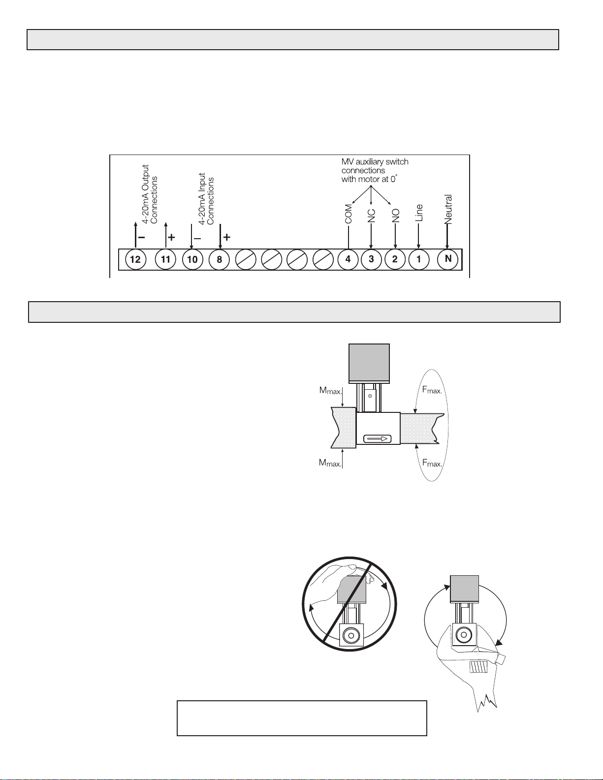
Wiring the DMA
1. Remove all power supplies.
2. Use minimum AWG #16 class 1 wiring for all terminals.
3. Remove cover to access the terminal block.
4. Only use the specified terminals. Terminal 8 must
be the + input and terminal 10 must be the - input.
Terminal Block for DMA
MOUNTING
Mounting DMA to a DMK/6 butterfly valve
1. Remove the clear cover from the DMA
2. Insert the shaft from the DMA into the linkage
of the DMK/6 until the motor is flush on the DMK/6
mounting plate. snug the set screw with a 2.5 mm
allen wrench. Torque to 15 lb-in.
3. Insert the M5 X 55 mounting bolts (supplied)
through the DMA motor mounting holes. Take care
not to break the plastic covers off of the bolt holes.
Hand tighten the 8mm hex nuts that are supplied.
Torque the bolts to 45 lb-in.
5. The cover has an intergrated protective barrier that
physically separates the wiring from the moving
adjustment switches and cams. Wiring must be
properly routed so that the cover can be installed.
6. For terminals 8 and 10, use properly sheilded wires, that
are grounded on both sides, and run through conduit
containing only low voltage (24V) wiring.
Mounting the DMK/6 to a shutoff valve
1. Turn off the gas supply.
2. Refer to the flow direction on the valve housing.
3. Note: Aluminum to Aluminum connection:
Coat inner and outer threads with a suitable
lubrcant before sealing the inner and outer threads.
4. DO NOT use any part of the DMA or the mounting
bracket of the DMK/6 assembly as a lever to
tighten! Use appropriate sized wrench.
5. Tighten connections. Use the chart below for
torque specifications.
6. Perform a complete leak test after installation.
DMK 707 710 712 715 720
Max. lb-in 560 750 875 940 1190
2 … 3
Page 3
DMA ACTUATOR CALIBRATION AND ADJUSTMENTS
Calibrating the DMA
Note: The red and yellow switches are factory set outside of
the 0 to 90˚ operating range. Do not change these adjustment dials until calibration is complete. DO NOT use these
switches in lieu of the calibration.
To Adjust Minimum Position
1. Apply a 4 mA DC input signal.
2. Turn the Y min (Zero) potentiometer (adjusting
range 0 to 100 % of stroke) to position the actua-
tor at the desired minimum position. Turning Y min
(Zero) CCW drives the minimum position towards
0˚.
To Adjust Maximum Position
1. Apply 20 mA DC input signal.
2. Turn the Y max (Span) potentiometer (adjusting
range 25 to 100 % of stroke) to position the actua tor at the desired maximum position. Turning Y max
(Span) CCW drives the setpoint towards 0˚.
Note: Y min (Zero) must be no more than 75 % of Y max
(Span) (reference: 90˚ = 100%). E.g. if the maximum position
is set at 85˚, the minimum position can be set at 64˚ maximum. (85˚ * 0.75 = 64˚).
Switch Adjustment:
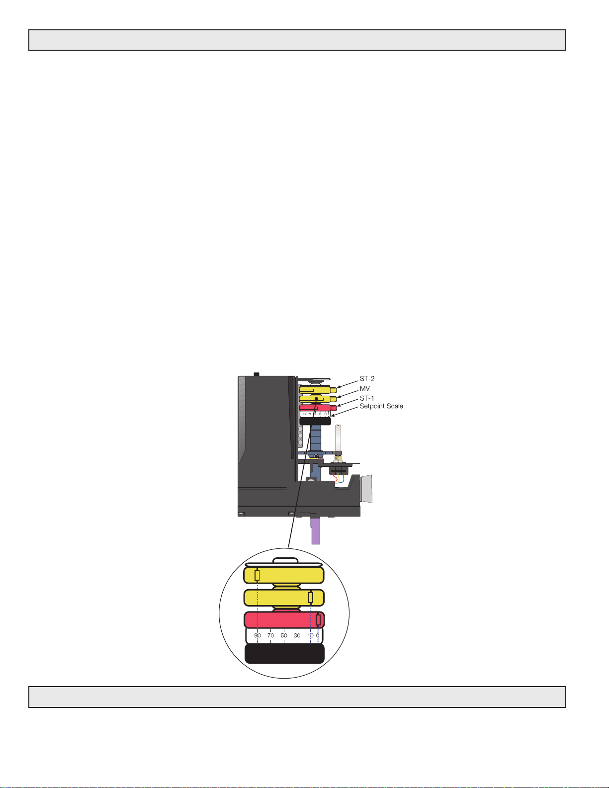
Note: Use the scale under the Red ST1 switch to field set
the switches.The DMA incorperates two limit switches that
limit the crank shaft from exceeding a set point if the zero
or span potentiometer fails. The DMA also has an
SPDT auxilary switch. All switches can be adjusted
anywhere over the 90˚stroke.
ST1 Limit Switch (Red): This switch limits the minimum position at 0˚ or more. Set the switch at approx.
1˚ LESS than the Y Min. setpoint. The small set
screw on the side of the red dial can be used for fine
tuning adjustment.
ST2 Limit Switch (Yellow): This switch limits the maxi-
mum position at 90˚ or less. Set the switch at approx. 1˚ MORE than the Y Max. setpoint. The small
set screw on the side of the yellow dial can be used
for fine tuning adjustment.
MV Auxiliary-Switch (Yellow): Set the switch to trip at
the desired setpoint using the scale under the Red
ST1 switch. When the motor is at 0˚, the NC contact 4
and 3 opens, and the NO contact 4 and 2 closes.
Description
NEMA 4 metal enclosure
3 … 3
ACCESSORIES
Order No.
240-456
 Loading...