

Page 1

DT4000and DT4100
High Resolution Digital Camera
User Manual
DuncanTech
11824 Kemper Rd.
Auburn, CA 95603
Phone: (530)-888-6565
Fax: (530)-888-6579
Web: www.duncantech.com
Email: [email protected]
Document Number: 9000-0005-04
Page 2

DuncanTech
DT4000 and DT4100 Camera User’s Manual Document Number: 90000005-02
Copyright 2002 Duncan Technologies, Inc. The information provided in this document
is believed to be accurate and reliable. However, no responsibility is assumed by
Duncan Technologies for its use; nor for any infringement of patents or other rights of
third parties which may result from its use. No license is granted by implication or
otherwise under the patent rights of Duncan Technologies. No parts of this manual may
be reproduced or transmitted in any form, or translated into any language for purposes
other than the purchaser’s personal use without the written permission of Duncan
Technologies. Duncan Technologies reserves the right to modify the present publication
without prior notice.
Reaching DuncanTech
Thank you for your purchase of a DuncanTech product. It is our priority to see that you
have the highest quality product possible and the information and support necessary to
get the optimum return on your investment. For further information not included in this
manual, or for information on DuncanTech’s other imaging products, please call:
DuncanTech
11824 Kemper Rd.
Auburn, CA 95603
Phone: (530)-888-6565
Fax: (530)-888-6579
Web: www.duncantech.com
Email: [email protected]
DT4000 User Manual - 9000-0005-04
Page 3

DuncanTech
Table of Contents
Introduction to the DT4000 and DT4100 Cameras............................................................... 4
Camera Operation................................................................................................................... 5
Physical Characteristics.......................................................................................................... 7
Camera Electrical Interface .................................................................................................... 9
Overview...............................................................................................................................9
Digital Video Data Output..................................................................................................10
CameraLink Interface........................................................................................................11
CameraLink Pixel Clock Rate........................................................................................... 12
Serial Port Communication Interface............................................................................... 16
Trigger Input....................................................................................................................... 17
Electrical Power Requirements......................................................................................... 19
DirectView Video Output...................................................................................................20
Camera Specifications ..........................................................................................................22
Camera Control and Configuration via RS-232 Communications.....................................23
RS-232 Command Set......................................................................................................23
Host Message Format.......................................................................................................23
Echo Message Format...................................................................................................... 24
Camera Command Set...................................................................................................... 25
Definition of Channel Number.......................................................................................25
SetChannelGain( ChannelNumber, Gain ) ..................................................................26
GetChannelGain( ChannelNumber )............................................................................ 27
SetChannelOffset( ChannelNumber, Offset )..............................................................28
GetChannelOffset( ChannelNumber )..........................................................................29
SetIntegrationTime( ChannelNumber, IntegrationTime )............................................ 30
SetTriggerMode()...........................................................................................................32
GetTriggerMode()...........................................................................................................33
SetOutputMux( Three Byte Value ) .............................................................................. 34
GetOutputMux()..............................................................................................................35
SetVideoMode(Value)....................................................................................................36
GetVideoMode().............................................................................................................37
GetGainCorrectionResult(ChannelNumber)................................................................39
SetPixelClockRate(Frequency).....................................................................................40
GetPixelClockRate()...................................................................................................... 40
SetAnalogColorBalance().............................................................................................. 41
GetAnalogColorBalance()............................................................................................. 42
SetZoomFactor()............................................................................................................43
SetVideoMux()................................................................................................................ 44
GetVideoMux()............................................................................................................... 45
SetCrosshairs() ..............................................................................................................46
GetCrosshairs ()............................................................................................................. 46
SetZoomFactor()............................................................................................................47
GetZoom Factor() ..........................................................................................................47
GetAllAverages()............................................................................................................ 48
GetRemoteHeadConfiguration()...................................................................................49
SetBayerMux() ...............................................................................................................50
GetBayerMux()...............................................................................................................50
DT4000 User Manual - 9000-0005-04
Page 4

DuncanTech
Introduction to the DT4000 and DT4100 Cameras
DuncanTech’s DT4000and DT4100 cameras are high-resolution, digital, progressive
scan, area cameras for monochrome and color imaging in a variety of applications. The
image sensor is a charge coupled device (CCD) array sensor. Primary features of the
camera are:
n Advanced optical, mechanical, and electronic design to produce high quality images
without distortion.
n Progressive scan operation for clear acquisition of images of moving targets
n Digital Image Output in CameraLink, EIA-644, or RS-422 format.
n “Smart” camera features for advanced control and processing
n RS-232 interface for configuration and control input
n Compact, rugged, package for harsh environments
n Control of gain and exposure time for the array
n Analog scaler gain of individual colors for good color balance
n Optional analog video image output via NTSC/PAL or progressive scan
n External trigger inputs with three operating modes
n Support for C-mount or F-mount camera lens
For detailed specifications, please see “Camera Specifications” on page 22.
DT4000 User Manual - 9000-0005-04
Page 5
DuncanTech
Camera Operation
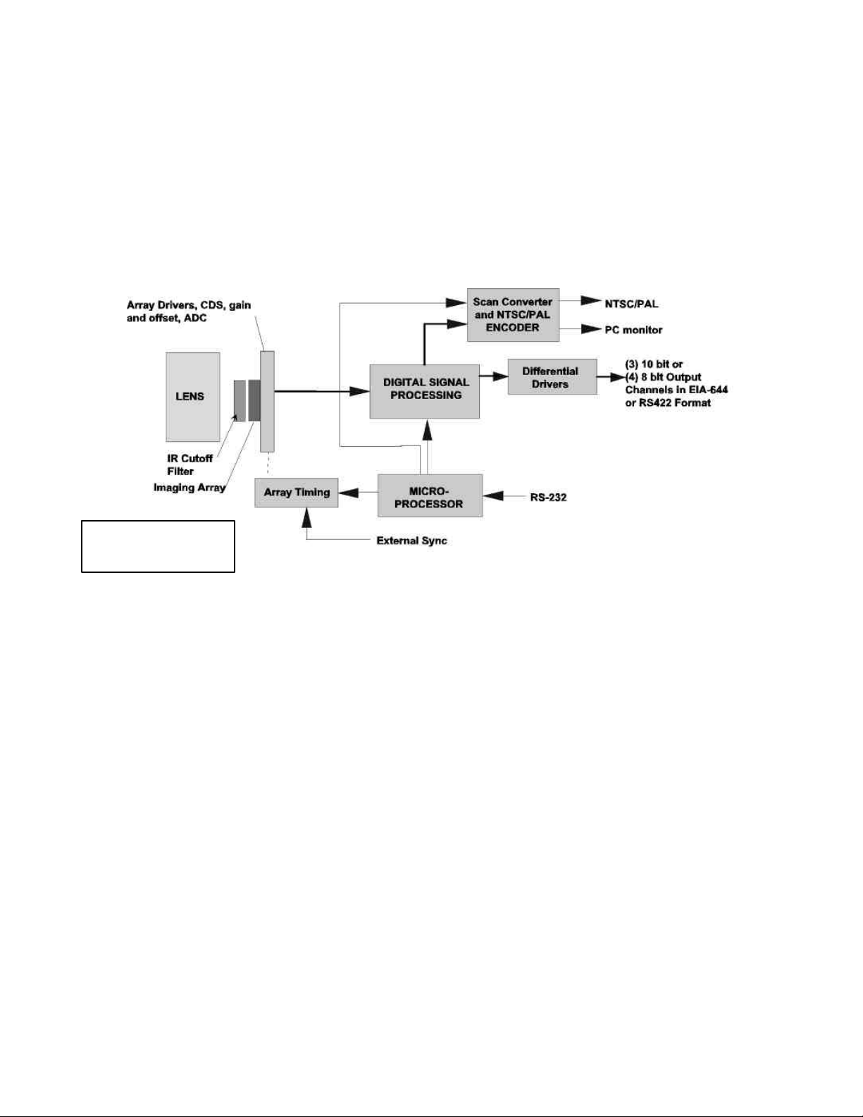
A functional diagram of DuncanTech’s DT4000 or DT4100 camera is shown in Figure 1
below. The camera utilizes a single CCD sensor to acquire the image. In color
configurations, the sensor has gel filters placed over the individual pixels that filter the
incoming light for red, green, and blue colors. Monochrome configurations use a single,
monochrome sensor.
Note: IR Cut Filter not
included in Monochrome
models.
Figure 1. Functional diagram – DT4000 and DT4100 camera
The output signal of the array is conditioned and digitized to a 10 bit digital value. Analog
gain and offset of the array circuitry can be used to optimize the signal levels. The
remainder of the camera electronics performs further image processing on the digital
image data and outputs the data for digital transmission and/or display. For color
configurations, the processing electronics converts the matrix of filtered RBG pixel
values to full resolution 24 or 30 bit RGB image data in a process known as “Color Filter
Array (CFA) Interpolation” or "Bayer Pattern Demultiplexing".
The camera includes an RS-232 communications interface to receive operational
commands and configuration data from an external control source. An embedded
microprocessor manages the communications and uses the operating parameters to
configure the other camera processing units. These parameters are stored in on-board
flash memory and are used to restore the camera to its proper operating configuration at
power-up.
Camera configuration and control options include the ability to set gain, and integration
time for the CCD and to set individual analog gains for each color in order to achieve
white balance. An internal multiplexer can be programmatically controlled to modify the
mapping of image data to the digital output ports. This enables the output of any
combination of color planes. External trigger inputs can be used to precisely control the
start of image acquisition. Three different triggering modes are available.
DT4000 User Manual - 9000-0005-04
Page 6

DuncanTech
Image data is output as digital pixel values at the digital output connector on the rear of
the camera. The camera’s digital image data output can be configured for the
CameraLink standard or parallel digital data in either EIA-644 or RS-422 differential
format. The CameraLink output is configured for a “Medium” implementation. Up to 32
pixels of data can be output in parallel. This output data can be programmatically
configured for either 8-bit or 10-bit resolution. When 8-bit resolution is selected, the
lower two bits of data are dropped. When configured for 8-bit operation, the camera can
output up to four “sets” or “taps” of image data for a total of 32 bits. In 10-bit mode, the
camera can output up to three “sets” or “taps” of data for a total of 30 bits. The on-board
multiplexer controls which data appears at each tap. This can be any combination of
processed or unprocessed image data.
The optional DirectView analog video output module adds the capability to convert the
digital image data to a standard analog video format, which can be output in addition to
the digital data. The analog video output mode can be selected with a camera control
command via the RS-232 port. Options for output format include NTSC or PAL
interlaced video or progressive scan RGB at 640x480, 800x600, 1024x768, or
1280x1024.
DT4000 User Manual - 9000-0005-04
Page 7
DuncanTech
Physical Characteristics
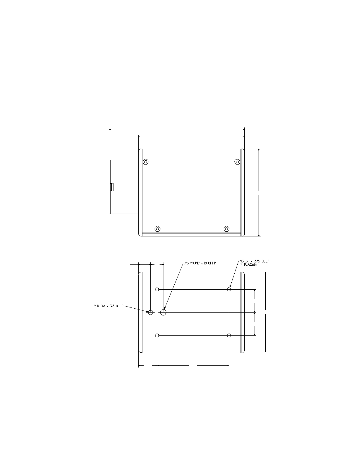
The DT4000 and DT4100 cameras are housed in a compact, rugged case. Physical
dimensions are shown in Figure 2 below. The maximum dimension is 89 x 97 x 107 mm
without lens and cable.
NOTE: All dimensions are metric
150
117
96.5
SIDE VIEW
13.4 14
79.420.6
BOTTOM VIEW
Figure 2. Camera Dimensions
25.4
88
25.4
DT4000 User Manual - 9000-0005-04
Page 8
DuncanTech
Lens adapter:
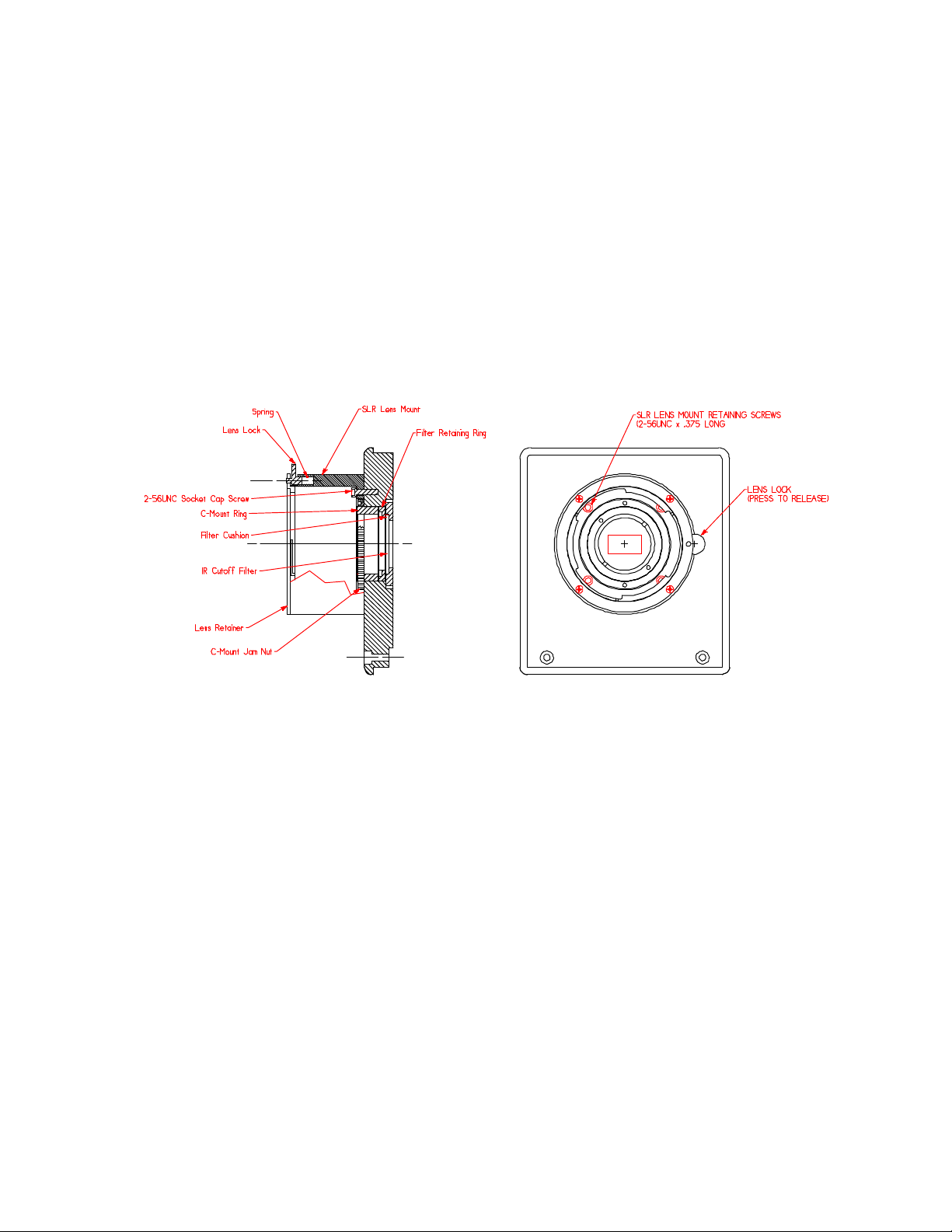
The DT4000 and DT4100 can support either F-Mount or C-Mount lenses. Your unit is
shipped with an adapter ring attached to the front panel that interfaces to F-Mount SLRtype lenses. In order to use the camera with C-Mount lenses this adapter ring must be
removed. To remove the F-Mount adapter, look inside of the adapter ring on the front of
the camera. There are four retaining screws located inside of this ring (see Figure 4) at
the base of the ring. These mount the adapter to the camera body. Use a 5/64” Allan
Wrench to remove these four screws. Now a C-Mount lens can be mounted to the lens
retaining ring on the front panel of the camera. It should be noted that many C-Mount
lenses are not designed for use with high-resolution arrays and therefore do not have
the small optical spot size necessary to achieve a high quality image with these arrays.
For optimal image quality, you should utilize high quality, high-resolution lenses.
Figure 3. Lens Mount and Locking Mechanism
The lens mount also includes a Lens Lock mechanism which locks the lens in place
when it is screwed into the mount. To release the lock, press down on the lock
mechanism tab and then unscrew the lens.
Mounting:
For optimal stability and best heat sinking the camera should be mounted using
the four threaded holes in the camera base plate (see Figure 2). The base plate
is a heat sink for the camera electronics. For best performance, mount the
camera to a material that provides good thermal contact and heat sinking
capability.
For convenience the cameras are configured with a standard
¼-20UNC tripod mount. This is the least stable mount and is recommended only
for temporary placement.
Weight without lens: .98 kg
Operating Temperature: 0-65 C
Power Supply: 12VDC, 8 Watts
DT4000 User Manual - 9000-0005-04
Page 9
DuncanTech
Camera Electrical Interface
Overview
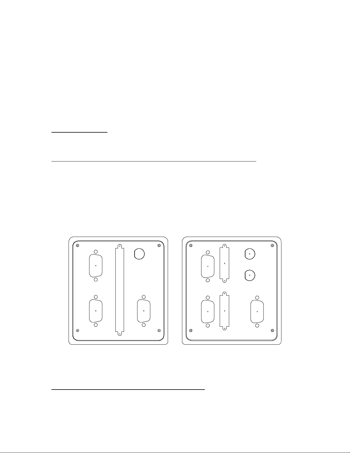
All electrical connectors are on the camera rear plate as shown in Figure 3. The
connectors on your unit will be depend on whether you purchased the camera with a
CameraLink interface or parallel digital interface, i.e. LVDS (EIA-644) or RS-422. An
overview of the connectors and their function is presented below followed by detailed
information for each connector.
Image Data Output
The electrical interface for image data varies depending on the configuration of the
camera as shown in Figure 4 below.
Digital Video (Parallel Digital Framegrabber Interface – LVDS or RS-422) - Cameras
configured for use with a standard parallel digital framegrabber interface in either LVDS
(EIA-644) or RS-422 versions will appear as shown at the left of Figure 4 below. The
Digital Video connector is the interface between the camera and the framegrabber in the
computer. This connector provides access to the digital pixel data and synchronization
signals from the camera. The specific connector used will vary depending on which
framegrabber the camera is configured for. A different output connector is provided for
each supported frame grabber in order to facilitate the use of standard cables.
TRIGGER
IN
TRIGGER
OUT
SERIAL PORT
ANALOG VIDEO
DIGITAL VIDEO
POWER
TRIGGER
SERIAL PORT
ANALOG VIDEOPOWER
BASE (PORT A, B, C)
MEDIUM (PORT D, E, F)
Figure 4. Camera Rear Panel
Std Framegrabber (left) and CameraLink (right) Configurations
Base and Medium Connections (CameraLink Interface) - Cameras configured for use
with the CameraLink standard digital interface will appear as shown at the right of Figure
4. The CameraLink rear panel interface supports both the Base and Medium
DT4000 User Manual - 9000-0005-04
Page 10

DuncanTech
Configurations as described in Section 3 of the CameraLink specification. Note that
CameraLink PortA, PortB and PortC are serviced by a single connector/cable marked
“BASE (PORT A,B,C)”. The Base configuration will support any three-tap configuration
running at 8 bits per color plane (i.e. 24bit RGB). Adding a fourth 8 bit tap or outputting
10 bits per color plane will require the additional use of the CameraLink connector
marked “MEDIUM (PORT D,E,F).
Serial Port - The RS-232 interface is provided via a standard DB-9 type connector. This
provides a communications interface to send and receive configuration and control
parameters.
Trigger - The external trigger input initiates the acquisition and transfer of a single frame
of data. Several triggering modes are available and are configured via the RS-232
control interface.
Power - The power connector consist of a standard, DB-9 type connector. Use the
power supply module provided with your camera.
Analog Video - This connector is used only in those systems that are configured with
the optional DirectView analog video output board. Video output is provided on a
standard DB15 connector. When the progressive scan RGB modes are selected,
(640x480, 800x600, 1024x768, and 1280x1024), a standard multisync type monitor can
be plugged directly into this DB15 connector. In order to drive NTSC or PAL monitors, a
special DB15 to coax converter cable is included with the camera.
Digital Video Data Output
The DT4000 and DT4100 camera outputs up to 32 bits of pixel data along with control
signals for synchronization. This output can be configured as four, 8-bit parallel data
channels (or “taps”) or three, 10-bit parallel data channels (or “taps”). These are referred
to as the camera output ports – Port 0, 1, 2, and 3 for 8-bit output mode and Port 0, 1,
and 2 for 10-bit output mode. For monochrome cameras, you can choose to use only
one output, or to route the image data to more than one output tap. Output configuration
is controlled via the RS-232 command interface.
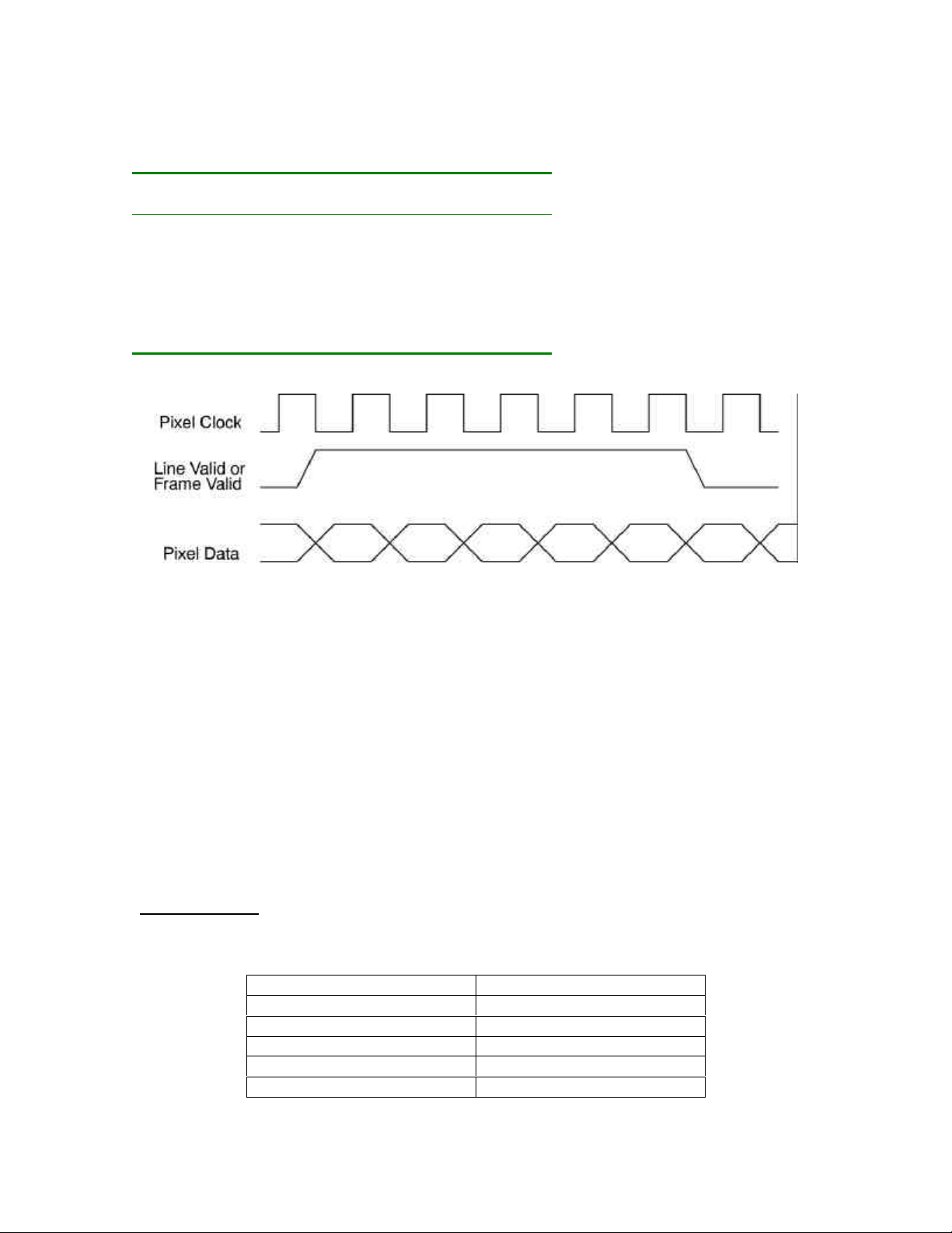
The control signals PIXCLK, LVAL, and FVAL are used to clock the image data into the
frame grabber. LVAL and FVAL are positive true and are coincident with the falling edge
of PIXCLK. The pixel data may be latched by the rising edge of PIXCLK. This conforms
to the Monochrome Digital Interface Specification AIA A15.08/3. The CameraLink
interface adds some additional signals that are detailed in the CameraLink interface
description below.
Control Signals
PIXCLK: Pixel clock output.
This signal is used to synchronously clock the digital video data and control signals.
LVAL: Line valid.
Asserted when a valid video line of data is being transferred.
FVAL: Frame valid.
Asserted when a valid video frame of data is being transferred.
DT4000 User Manual - 9000-0005-04
Page 11
DuncanTech
The control signals are characterized by the following parameters and exhibit the
behavior shown in the timing diagram below.
DT4000
(10 fps)
DT4100
(10 fps)
Pixel Clock Rate 22.6 Mhz 22.6 MHZ
Horizontal Total Count 1892 pixels 2232 pixels
Horizontal Active Count 1600 pixels 1920 pixels
Horizontal Blank Count 292 pixels 312 pixels
Vertical Total Count 1214 lines 1094 lines
Vertical Active Count 1200 lines 1080 lines
Vertical Blank Count 14 lines 14 lines
Note that the CameraLink interface additionally requires the use of the DVAL
signal.
Figure 5. Timing Diagram for Digital Video Output
CameraLink Interface
The Duncan Technologies CameraLink interface supports both the Base and Medium
Configurations described in Section 3 of the CameraLink specification. Please refer to
this specification for information regarding pin assignments and connector information.
The DT camera Ports are mapped to the CameraLink ports in the following manner
depending on whether the camera is operating in 8 bit/pixel or 10 bit/pixel mode. Note
that CameraLink PortA, PortB and PortC are serviced by a single connector/cable. The
addition of PortD requires the use of a second connector/cable.
8 bit/pixel Mode
In this mode the 8 bit Ports from the DT camera are mapped into the 8 bit CameraLink
Ports in the following manner.
DT Camera Ports (8 bit) CameraLink Ports (8 bit)
Port0 PortA
Port1 PortB
Port2 PortC
Port3 PortD
DT4000 User Manual - 9000-0005-04
Page 12

DuncanTech
Note that in the case of a 24 bit RGB image, only Ports A, B and C are used and a single
cable (Base) to the CameraLink frame grabber suffices to transfer all of the data. The
addition of a fourth 8 bit port (Camera Port 3 mapped to CameraLink PortD) requires the
use of a second cable (Medium configuration) to the frame grabber.
10 bit/pixel Mode
In this mode the 10 bit Ports from the DT camera are mapped into the 8 bit CameraLink
Ports in the following manner. This configuration requires the use of both the Base and
Medium CameraLink connections.
DT Camera Ports (10 bit) CameraLink Ports (8 bit)
Port0 PortA (A0 - A7), PortB (B0-B1)
Port1 PortB (B2-B7), PortC (C0-C3)
Port2 PortC (C4-C7), PortD (D0-D5)
CameraLink Pixel Clock Rate
The CameraLink specification requires a minimum pixel clock rate of 20 MHz. Some
DuncanTech camera models operate with a pixel clock rate of less than 20 MHz. In this
case, for the CameraLink transmission the pixel clock is doubled. The DVAL (DataValid)
signal is used to indicate valid pixel values in the data stream. The receiving
CameraLink framegrabber must utilize the DataValid function in order to correctly
interpret the incoming data stream.
Digital Video Connector: Framegrabber Options
The pin assignments for various Digital Video Connectors follow.
DT4000 User Manual - 9000-0005-04
Page 13
National Instruments PCI-1424 Framegrabber
Connector: AMP786577-9 100 pin D-type subminiature
Digital Video Connector Pinout for
National Instruments PCI-1424
Pin Signal Pin Signal
1 Out10+ 51 Out26+
2 Out10- 52 Out263 Out11+ 53 Out27+
4 Out11- 54 Out275 Out12+ 55 Out28+
6 Out12- 56 Out287 Out13+ 57 Out29+
8 Out13- 58 Out29-
9 Out14+ 59 Out30+
10 Out14- 60 Out3011 Out15+ 61 Out31+
12 Out15- 62 Out3113 Out16+ 63 Out32+
14 Out16- 64 Out3215 Out17+ 65 Out33+
16 Out17- 66 Out3317 Out18+ 67 Out34+
18 Out18- 68 Out3419 Out19+ 69 Out35+
20 Out19- 70 Out3521 Out20+ 71 Out36+
22 Out20- 72 Out3623 Out21+ 73 Out37+
24 Out21- 74 Out3725 Out22+ 75 Out38+
26 Out22- 76 Out3827 Out23+ 77 Out39+
28 Out23- 78 Out3929 Out24+ 79 Out40+
30 Out24- 80 Out4031 Out25+ 81 Out41+
32 Out25- 82 Out4133 Trig1+ 83
34 Trig1- 84
35 85
36 86
37 87
38 88
39 89
40 90
41 Fval+ 91
42 Fval- 92
43 Lval+ 93 RS232out
44 Lval- 94 RS232in
45 Ctrl+ 95
46 Ctrl- 96
47 97
48 98
49 Pixclk+ 99 Ground
50 Pixclk- 100 Ground
DuncanTech
DT4000 User Manual - 9000-0005-04
Page 14
Imaging Technologies PC-DIG Framegrabber
Connector: AMP175925-9 100 pin D-type subminiature
Digital Video Connector Pinout for
Imaging Technology PC-DIG
Pin Signal Pin Signal
1 Out10+ 51 Out26+
2 Out10- 52 Out26-
3 Out11+ 53 Out27+
4 Out11- 54 Out27-
5 Out12+ 55 Out28+
6 Out12- 56 Out28-
7 Out13+ 57 Out29+
8 Out13- 58 Out29-
9 Out14+ 59 Out30+
10 Out14- 60 Out3011 Out15+ 61 Out31+
12 Out15- 62 Out3113 Out16+ 63 Out32+
14 Out16- 64 Out3215 Out17+ 65 Out33+
16 Out17- 66 Out3317 Out18+ 67 Out34+
18 Out18- 68 Out3419 Out19+ 69 Out35+
20 Out19- 70 Out3521 Out20+ 71 Out36+
22 Out20- 72 Out3623 Out21+ 73 Out37+
24 Out21- 74 Out3725 Out22+ 75 Out38+
26 Out22- 76 Out3827 Out23+ 77 Out39+
28 Out23- 78 Out3929 Out24+ 79 Out40+
30 Out24- 80 Out4031 Out25+ 81 Out41+
32 Out25- 82 Out4133 Lval+ 83
34 Lval- 84
35 Fval+ 85
36 Fval- 86
37 Ground 87
38 Ground 88
39 Pixclk+ 89
40 Pixclk- 90
41 91
42 92
43 93
44 94
45 95
46 96
47 Ctrl+ 97
48 Ctrl- 98
49 99
50 100
DuncanTech
DT4000 User Manual - 9000-0005-04
Page 15
Matrox Corona
Connector: AMP175925-0 80 pin D-type subminiature
Digital Video Connector Pinout for
Matrox Corona
Pin Signal Pin Signal
1 Out10+ 41 Out11+
2 Out10- 42 Out11-
3 Out12+ 43 Out13+
4 Out12- 44 Out13-
5 Out14+ 45 Out15+
6 Out14- 46 Out15-
7 Out16+ 47 Out17+
8 Out16- 48 Out17-
9 Out18+ 49 Out19+
10 Out18- 50 Out1911 Out20+ 51 Out21+
12 Out20- 52 Out2113 Out22+ 53 Out23+
14 Out22- 54 Out2315 Out24+ 55 Out25+
16 Out24- 56 Out2517 Out26+ 57 Out27+
18 Out26- 58 Out2719 Out28+ 59 Out29+
20 Out28- 60 Out2921 Out30+ 61 Out31+
22 Out30- 62 Out3123 Out32+ 63 Out33+
24 Out32- 64 Out3325 Ground 65 Ground
26 66
27 67 Lval+
28 68 Lval29 69 Fval+
30 70 Fval31 Trig1+ 71
32 Trig1- 72
33 73 Ctrl+
34 74 Ctrl35 75
36 76
37 77
38 78
39 79 Pixclk+
40 80 Pixclk-
DuncanTech
DT4000 User Manual - 9000-0005-04
Page 16
DuncanTech
Serial Port Communication Interface
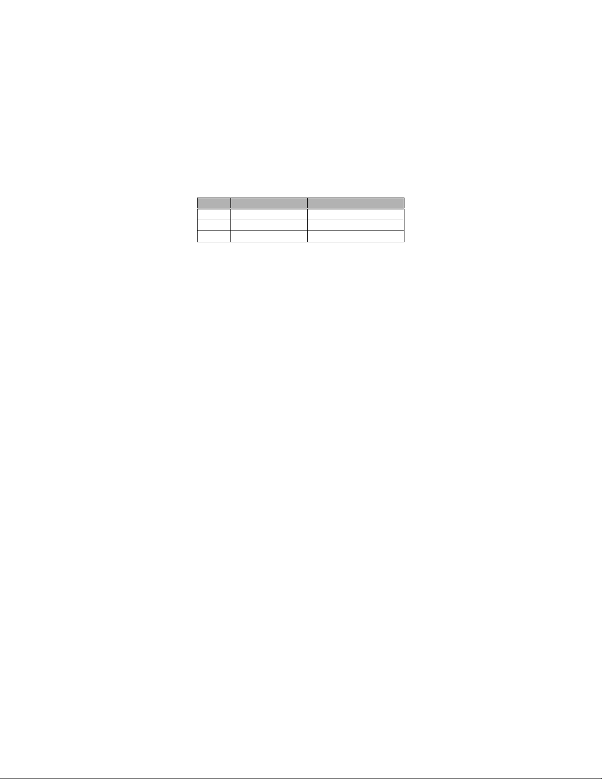
The RS-232 interface to the camera is provided via a standard, DB-9 type connector on
the rear panel with the following connections. The data character format is 8N1 (8 data
bits + no parity + 1 stop bit). Baud rate is 9600 bps. No handshaking signals are
supported. For detailed information on the command protocol, see "Camera Control and
Configuration via RS-232 Communications".
RS-232 Connector Pin Assignments
Pin Connection Notes
2 Transmit Host PC output
3 Receive Host PC input
5 Ground
DT4000 User Manual - 9000-0005-04
Page 17
DuncanTech
Trigger Input
The external trigger signal initiates the acquisition and transfer of a single frame of data
in one of several possible ways. The polarity of the External Trigger signal is user
programmable. The external trigger signal input may be derived from one of two
sources: 1) the Trigger BNC connector on the rear panel or 2) the trigger signal pins on
the Digital Video Connector. The source of the trigger input is selected via an RS-232
command. The optically coupled, rear panel BNC input requires a trigger voltage from 4
to 10 volts in amplitude and capable of sourcing at least 10 mA.
Trigger Modes
Image acquisition occurs in four different modes. Three of these modes require an
external trigger signal to initiate a new acquisition. These triggered modes provide
different methods of controlling the start of image acquisition and the duration of the
integration time. The triggering mode is selected with via an RS-232 command. The
triggering modes are described in detail below.
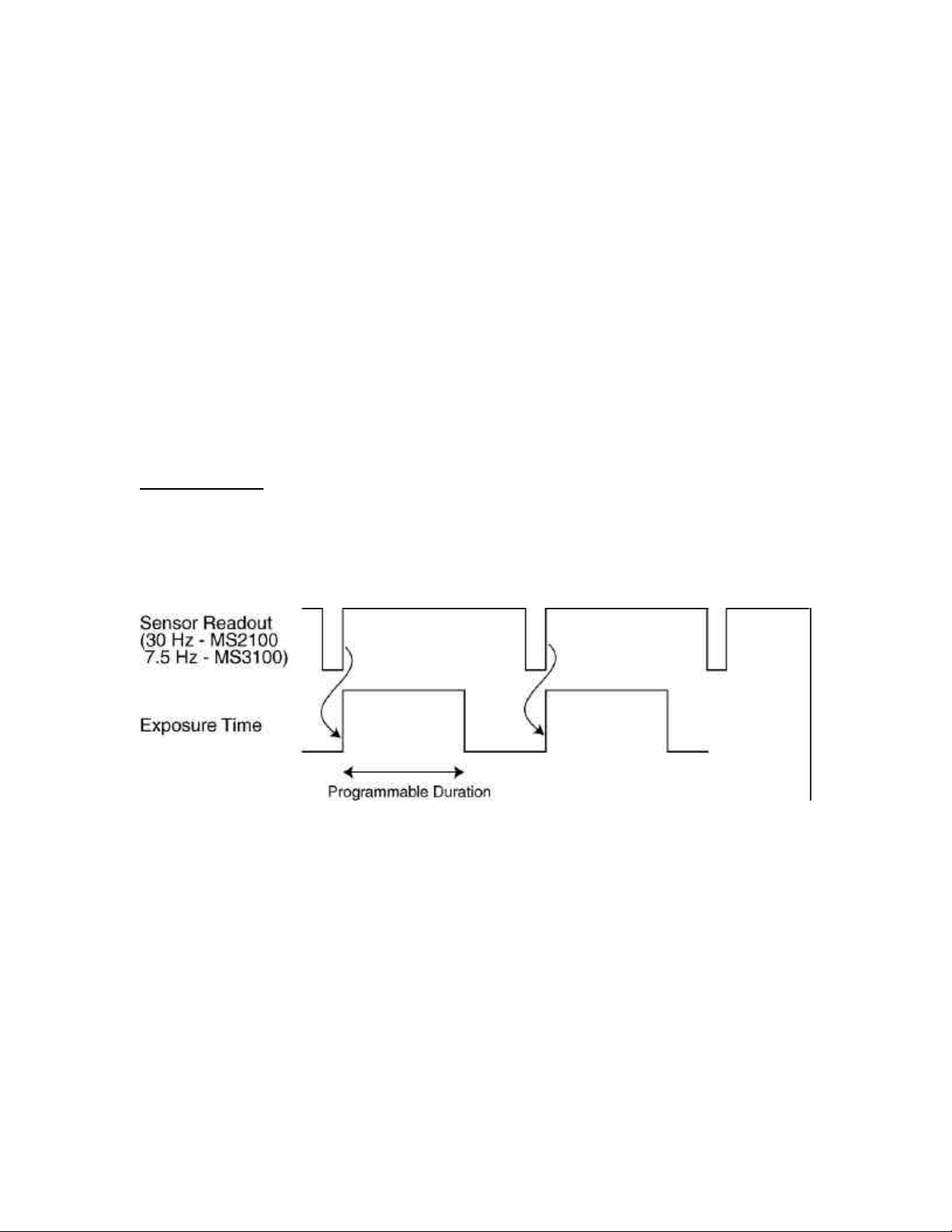
Free Run Mode (Internal Sync)
This mode requires no external control signals and provides high frame rates by
overlapping the readout time with the exposure time. An internally generated, fixed
frequency trigger signal initiates the readout of the current frame and starts the exposure
time for the next frame. The frame rate is controlled internally. Integration time is
programmable.
Figure 6. Free Run Mode - No External Trigger
DT4000 User Manual - 9000-0005-04
Page 18
DuncanTech
Edge Controlled (External Trig)
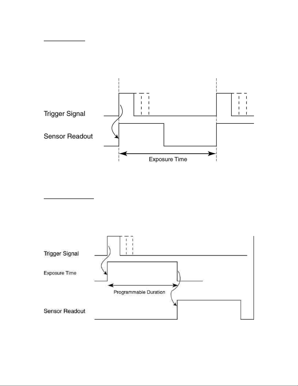
This mode provides high frame rates by overlapping the readout time with the integration
time. The active edge of EXT TRIG initiates the readout of the last frame of data and
starts the exposure time for the next frame. The exposure time is defined by the time
between two successive leading edges of the trigger signal. The minimum time between
trigger pulses must be at least one frame readout period.
Figure 7. Edge Controlled Trigger Mode
Integrate and Dump (External Trig, programmable)
In this mode the active edge of EXT TRIG initiates the start of a programmable
integration time. At the end of the integration time the readout takes place. After the
readout, the system is ready for another EXT TRIG signal. The integration time
programmed via RS-232 commands and can be set with CameraLink, DuncanTech’s
camera control program.
Figure 8. Integrate & Dump - Edge Controlled Trigger Mode
DT4000 User Manual - 9000-0005-04
Page 19
DuncanTech
Integrate and Dump (External Trig, level controlled)
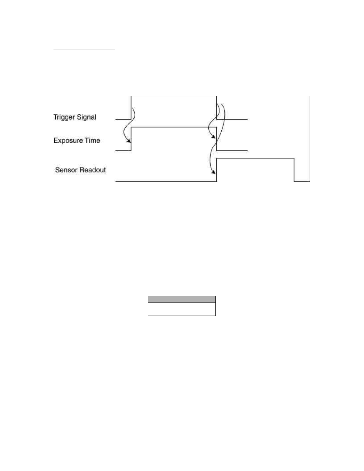
In this mode both edges of EXT TRIG are active. The leading edge initiates the start of
the integration time and the falling edge defines the end of the integration time. The
falling edge also initiates the readout period. The minimum time between two
successive leading edges of the trigger signal is the exposure time plus one frame
readout period.
Figure 9. Integrate & Dump - Level Controlled Trigger Mode
Electrical Power Requirements
The DT4000 and DT4100 series cameras have built-in power conditioning. The camera
requires 12Volts +/- 5% at 1 amps.
Maximum power dissipation for the DT4000 or DT4100 camera is 12 Watts.
The power connector consists of a standard, DB-9 type connector on the rear panel of
the camera with the following connections.
Power Connector Pinout
Pin Connection
1 Ground
2 +12V
DT4000 User Manual - 9000-0005-04
Page 20
DuncanTech
DirectView Video Output
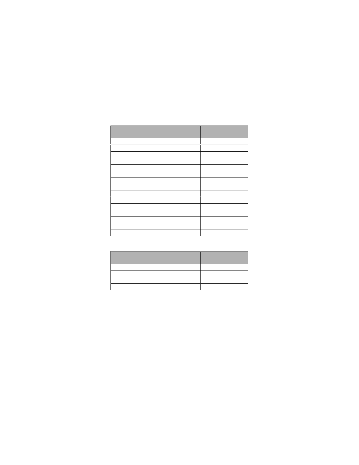
For those cameras purchased with the analog video output options, the analog video is
available on a DB15 connector located on the camera rear panel. Video output is
provided in NTSC or PAL formats (Composite or S-Video) as well as non-interlaced
video for multisync (PC type) monitors. The format of the video output signal is selected
via the RS232 interface. A standard DB15 to coax cable can be used to interface with
NTSC/PAL monitors.
Analog Video Connector Pinout
Progressive Scan NTSC/PAL
PIN Output Output
1 Red S-Video (C)
2 Green Composite Video
3 Blue S-Video (Y)
4 N/C
5 N/C
6 Red Ground Video Gnd
7 Green Ground Video Gnd
8 Blue Ground Video Gnd
9 N/C
10 Ground
11 N/C
12 N/C
13 Horiz. Sync
14 Vert. Sync
15 N/C
DB15 to Coax Cable
NTSC/PAL Interlaced RGB
Coax Output Output
Red S-Video (C) Red
Green Composite Video Green
Blue S-Video (Y) Blue
White or Gray Composite Sync
DT4000 User Manual - 9000-0005-04
Page 21
DuncanTech
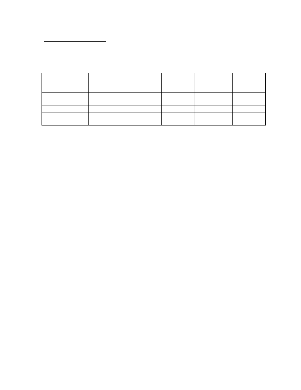
Supported Video Modes
The table below lists the video signal formats that can be output from the Analog Video
connector. The output mode is selected via a camera control command. An appropriate
monitor type that can support the selected mode must be used to view the resulting
image.
Mode Resolution Line Rate Frame
Rate
Pixel Clock
Rate
NTSC 640 X 504 15.7 KHz 60 Hz Intl 12.27 MHz (interlaced)
PAL 768 X 600 15.6 KHz 50 Hz Intl 14.75 MHz (interlaced)
VGA (640 x 480) 640 X 480 31.5 KHz 60 Hz 25.175 MHz
800 x 600 800 X 600 37.9 KHz 60 Hz 40 MHz
1024 x 768 1024 X 768 48.4 KH z 60 Hz 65 MHz
1280 x 1024 1280 X 1024 64.0 KHz 60 Hz 108 MHz
DT4000 User Manual - 9000-0005-04
Page 22
DuncanTech
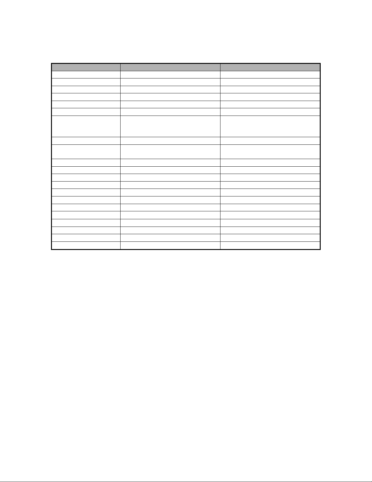
Camera Specifications
D4000 DT4100
Imaging Device 1” Interline Transfer CCD HDTV Interline Transfer CCD
Resolution 1600(H) x 1200(V) 1920(H) x 1080(V)
Pixel Size 7.4 x 7.4 micron 7.4 x 7.4 micron
Pixel Clock Rate 22.6 MHz max 22.6 MHz max
Sensing Area 11.8 x 8.9 mm 14.2 x 8 mm
Frame Rate 10 frames per second max 10 frames per second max
Digital Output 8 bits x 4 taps or 10 bits x 3 taps
(32 bits max) EIA644, RS422, or
CameraLink
Data Transfer Rate 22.6 MHz (10 fps) 22.6 MHz (10 fps)
Digital Control Signals Pixclk, Fval, Lval, Dval, and Ext
Trigger
Signal/Noise 60 dB at 5 fps 60 db at 5 fps
Lens Mount C Mount or F Mount C Mount or F Mount
Electronic Shutter 1/10,000 – 1/10 sec 1/10,000 – 1/10 sec
Gain Selection -4 - 32 dB -4 - 32 dB
Offset Adjustment Offset auto-zeroed with every line Offset auto-zeroed with every line
External Trigger Input BNC or Digital Video Connector BNC or Digital Video Connector
Control Input RS-232 port RS-232 port
Operating Temp
Operating Voltage 12 volts 12 volts
Power Consumption 12 Watts 12 Watts
Weight .98 kg .98 kg
0-65º C 0-65º C
8 bits x 4 taps or 10 bits x 3 taps
(32 bits max) EIA644, RS422, or
CameraLink
Pixclk, Fval, Lval, Dval, and Ext
Trigger
DT4000 User Manual - 9000-0005-04
Page 23

DuncanTech
Camera Control and Configuration via RS-232 Communications
RS-232 Command Set
Communication between the host and the camera takes place by way of the transmission of
message packets from one to the other. Communication is always initiated by the host in the
form of a host message packet (described below). The camera responds with an echo
message packet (described below) which may or may not contain message bytes. Commands
that perform functions (such as setting parameters) are echoed back to the host after the
function has been performed, with no message bytes. A status flag indicates if the action was
successful or not. Commands from the host that expect data in return (like getting gain or
offset values) are echoed with the requested data in the form of message bytes along with a
status flag which indicates if the action was successful or not.
Note: The camera requires that a command sequence be executed in a handshaking fashion.
When the host has sent a command and is waiting for the echoed response from the camera,
no additional commands may be sent to the camera. New commands may only be sent to the
camera when the previous command has been completed and the status echo received.
Violating this rule may result in unpredictable results.
Host Message Format
The format for all messages transmitted to the camera will be:
STX <”size of message” LSB> <”size of message” MSB> <command byte>
<message bytes> <checksum byte>
where:
STX => ASCII Start Transmission character ($02).
“size of message” LSB => Least-significant byte of 16-bit size of
message field. (Note that the size value
does not include the STX byte, the “size of
message” bytes, or the checksum byte.)
“size of message” MSB => Most-significant byte of 16-bit “size of
message” field.
command byte => Unique byte for each host command
message bytes => Zero or more message/data bytes. (Exact
number determined by the parameters of
the command.)
checksum => 8 bit, two's complement of sum of message
bytes (does not include STX or “size of
message” bytes)
23
Rev 0.3 – 3/14/02
Page 24

Checksum calculation: In order to calculate the check sum for any given command,
accumulate the 8-bit sum off all bytes that constitute the command
and it’s message bytes. Do NOT include the STX and “size of
message” bytes in this sum. Having accumulated this sum, take
the twos compliment of the sum. This will be the command
checksum value. In C, the twos compliment of the sum <sumval>
can be calculated as:
<Twos comp val> = -<sumval>;
Echo Message Format
Once a command has been received at the camera, it will be processed and the command
will be echoed back to the host for verification. The format for all echoed messages
transmitted from the camera is:
STX <”size of message” LSB> <”size of message” MSB> <command byte>
<message bytes> <status byte> <checksum byte>
where:
STX => ASCII Start Transmission character
($02).
DuncanTech
“size of message” LSB => Least-significant byte of 16-bit size
“size of message” MSB => Most-significant byte of 16-bit size of
command byte Unique byte for each host command
message bytes Zero or more message/data bytes.
status byte Indicates success or failure of the
checksum 8 bit, two's complement of sum of
Allowable values for the status bytes include:
of message field. (Note that the size
value does not include the STX
byte, the size of message bytes or
the checksum byte.)
message field giving the number of
bytes to follow in message field.
disposition of the command
message bytes (does not include
STX or size bytes but does include
the status byte)
CommandComplete 0x00 Command executed without error.
CommandFailure 0x01 Command execution failed.
ChecksumFailure 0x02 Checksum calculation failed
UnrecognizedCommand 0x03 Command was not recognized
24
Rev 0.3 – 3/14/02
Page 25
DuncanTech
Camera Command Set
The following lists each command that is recognized by the camera, it’s parameters, structure,
and expected echo.
Definition of Channel Number
Many of the commands that follow will refer to “Channel Number” as a parameter. The meaning
and value of this parameter will vary depending on what model of camera you are working with.
The camera-imaging engine includes three channels for image data. In 3-CCD cameras, there
is one channel per CCD sensor. In 1-CCD cameras, there is only sensor which is controlled by
the electronics for “Channel 3”. In remote head cameras, the channel values used in the
commands correspond to Head 1, 2, and 3 respectively. Assignment of head numbers is
determined by which connector on the front panel a given head is plugged into.
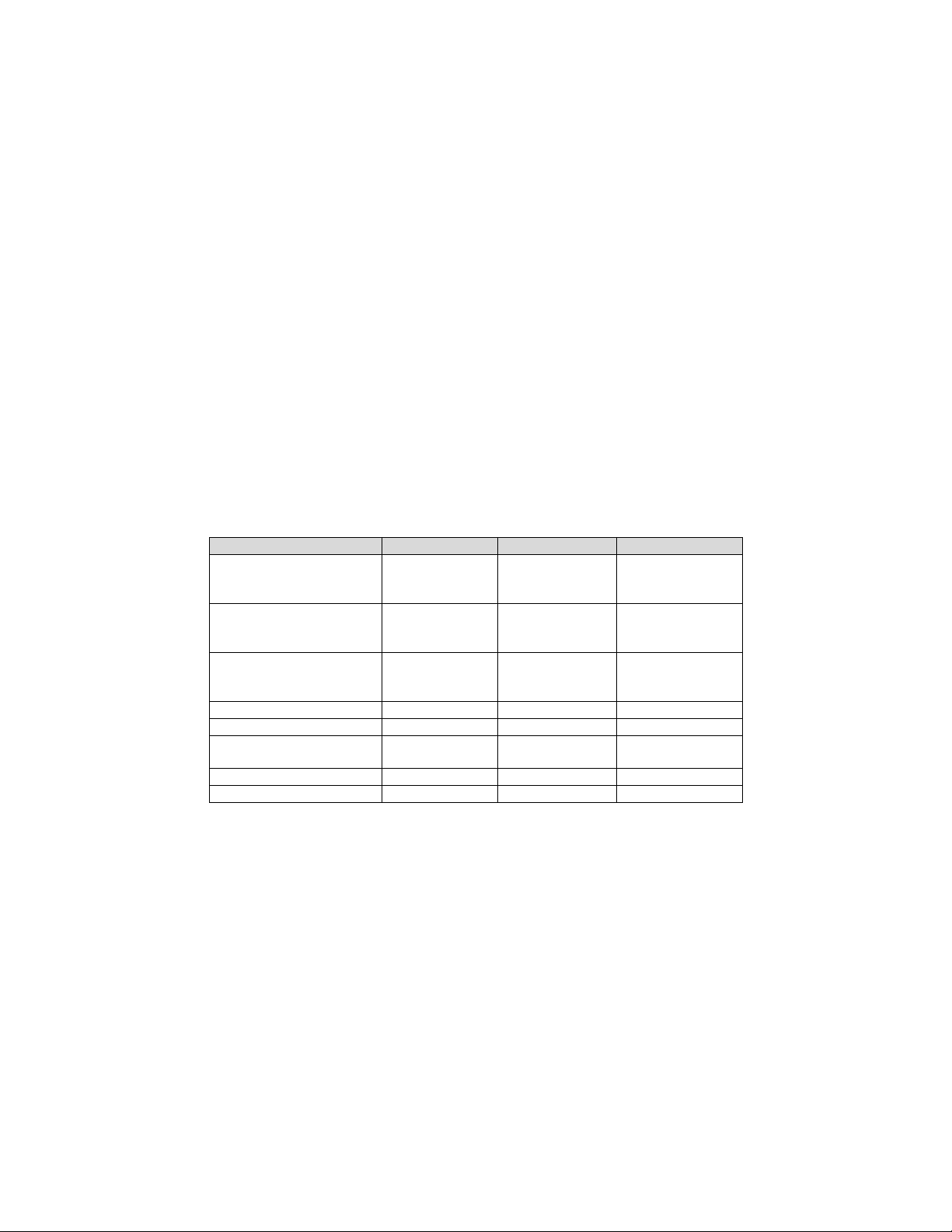
The correlation between the Channel No parameter for the following commands and the various
camera models is detailed in the table below.
Table 1. Definition of Channel No Parameter
Camera Configuration Channel 1 Channel 2 Channel 3
MS2100-RGB
MS2150-RGB
MS3100-RGB
MS2100-CIR
MS2150-CIR
MS3100-CIR
MS2100-RGB/CIR
MS2150-RGB/CIR
MS3100-RGB/CIR
MS2200-RGB Green Sensor Red Sensor Blue Sensor
MS2200-CIR Red Sensor IR Sensor Green Sensor
DT1100-RGB
DT1100-Mono
DT1200 Not used Not used Linear Sensor
RH1100 Head 1 Sensor Head 2 Sensor Head 3 Sensor
Green Sensor Red Sensor Blue Sensor
Red Sensor IR Sensor Green Sensor
Red Sensor IR Sensor Blue/Green
Sensor
Not used Not used RGB or Mono
Sensor
25
Rev 0.3 – 3/14/02
Page 26
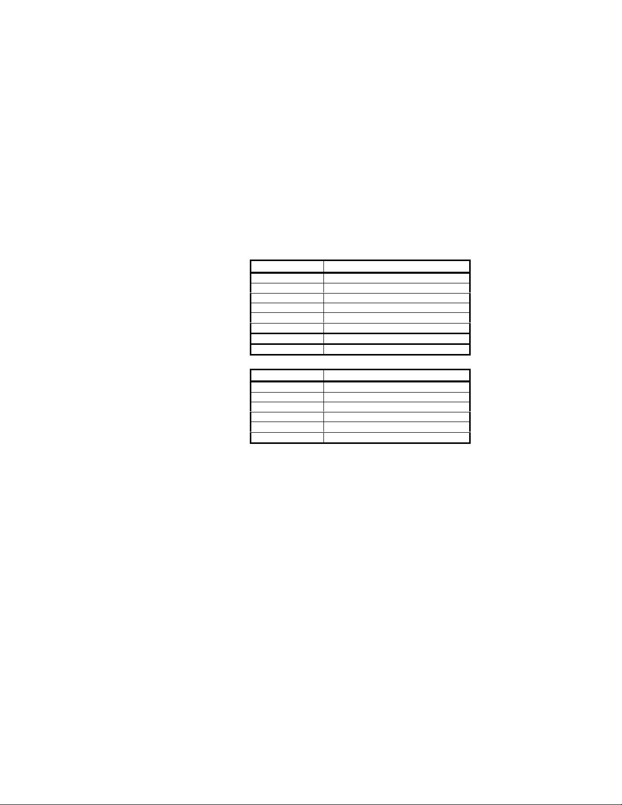
SetChannelGain( ChannelNumber, Gain )
Sets the specified channel to the specified gain value where:
ChannelNumber = 1, 2, or 3
Gain is a 16-bit value calculated as follows:
For MS2100 and MS2150
Gain = 0 - 384 where the resulting gain value in dB is calculated as:
gain = (.094)*DigitalNumber-4 dB
For all other DuncanTech Cameras
Gain = 95 – 1023 counts where the resulting gain value is calculated as:
gain =. (0366)*(DigitalNumber-95)+2.0 dB
Message Byte Contents
0 $02 - STX
1 $04 - LSB size
2 $00 - MSB size
3 $02 - command byte
4 channel number
5 gain - LSB
6 gain - MSB
7 $?? - checksum
Echo:
Message Byte Contents
0 $02 - STX
1 $02 - LSB size
2 $00 - MSB size
3 $02 - command byte
4 status
5 $?? - checksum
DuncanTech
26
Rev 0.3 – 3/14/02
Page 27
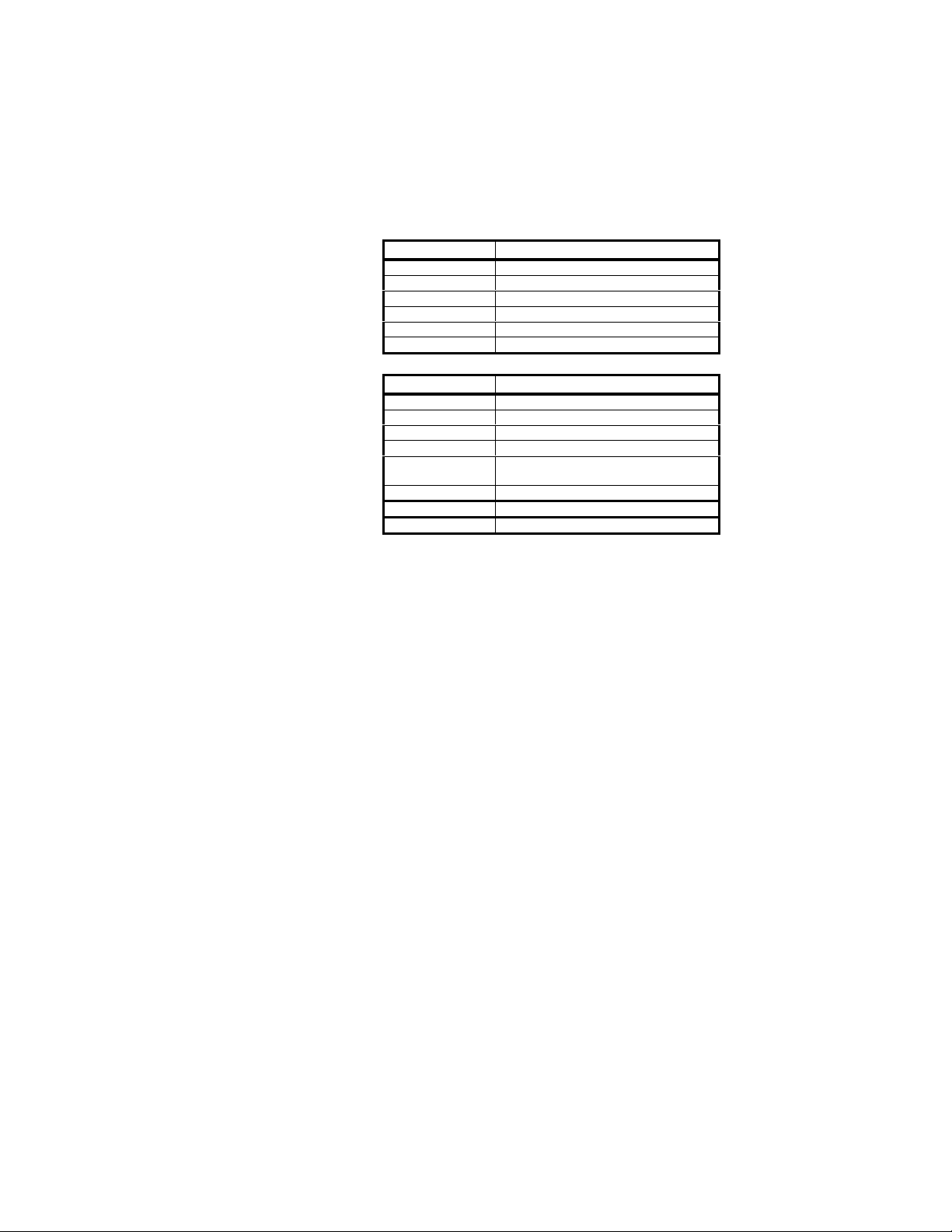
GetChannelGain( ChannelNumber )
Requests the camera to return the present gain setting for the specified channel.
Returns message bytes and status.
ChannelNumber = 1, 2, or 3
Message Byte Contents
0 $02 - STX
1 $02 - LSB size
2 $00 - MSB size
3 $03 - command byte
4 channel number
5 $?? - checksum
Echo:
Message Byte Contents
0 $02 - STX
1 $05 - LSB size
2 $00 - MSB size
3 $03 - command byte
4 channel number
5 gain (LSB)
6 gain (MSB)
7 $?? - status
8 $?? - checksum
DuncanTech
27
Rev 0.3 – 3/14/02
Page 28
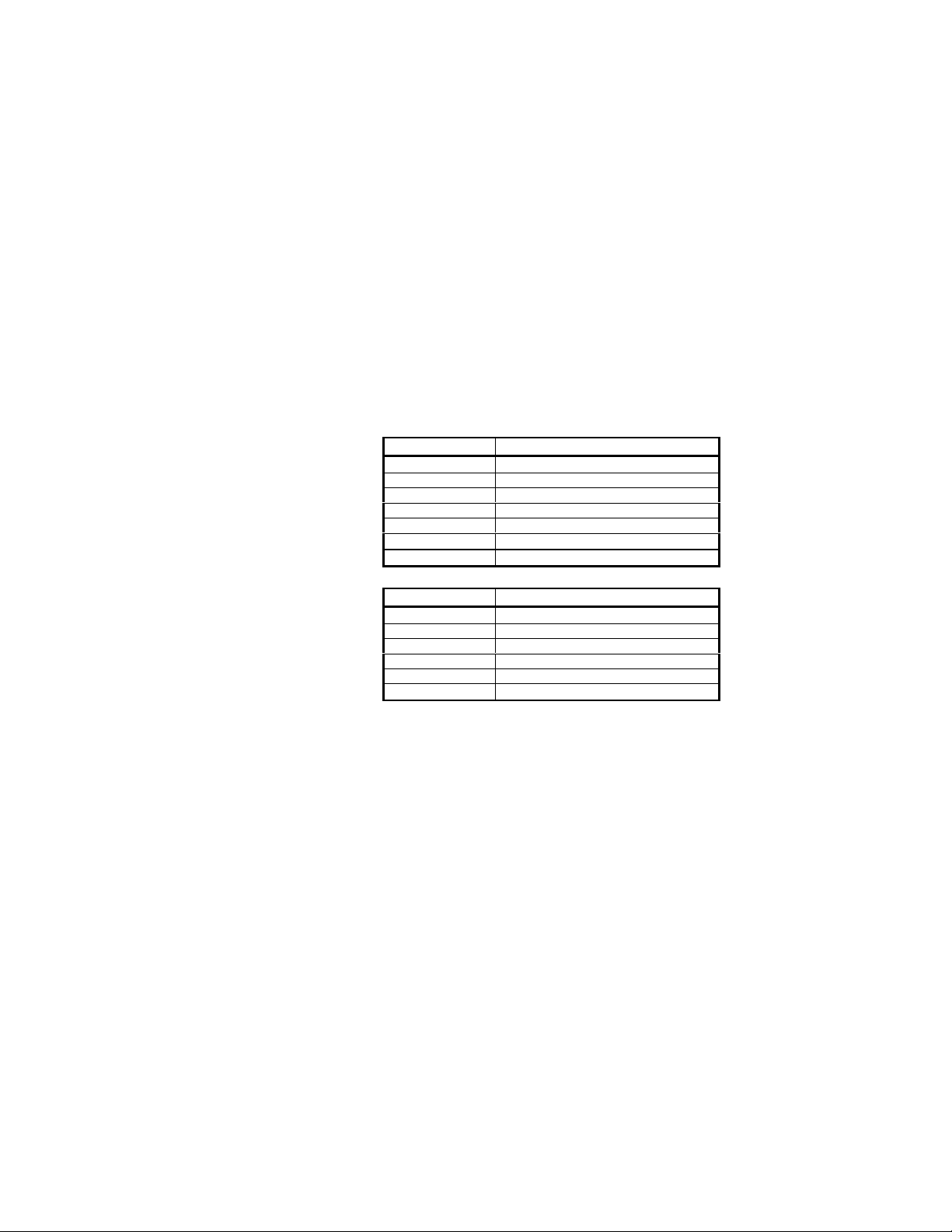
SetChannelOffset( ChannelNumber, Offset )
Adds the specified offset to the specified channel. The offset value is in an 8 bit, straight
binary format. [Note: DuncanTech’s Correrlated Double Sampling circuitry
automatically removes any offset at the beginning of every line. Due to this advanced
technology, it has been found that this particular command is not needed because
image signal does not have an offset. However, the offset command is accessible
programmatically and may have utility for specific applications. The comannd continues
to be included her for completeness.
ChannelNumber = 1, 2, or 3
For Cameras with AD9841
Offset = 0 – 127
For Cameras with AD9841
Offset = 0 - 63
Message Byte Contents
0 $02 - STX
1 $03 - LSB size
2 $00 - MSB size
3 $04 - command byte
4 channel number
5 offset
6 $?? - checksum
Echo:
Message Byte Contents
0 $02 - STX
1 $02 - LSB size
2 $00 - MSB size
3 $04 - command byte
4 status
5 $?? - checksum
DuncanTech
28
Rev 0.3 – 3/14/02
Page 29
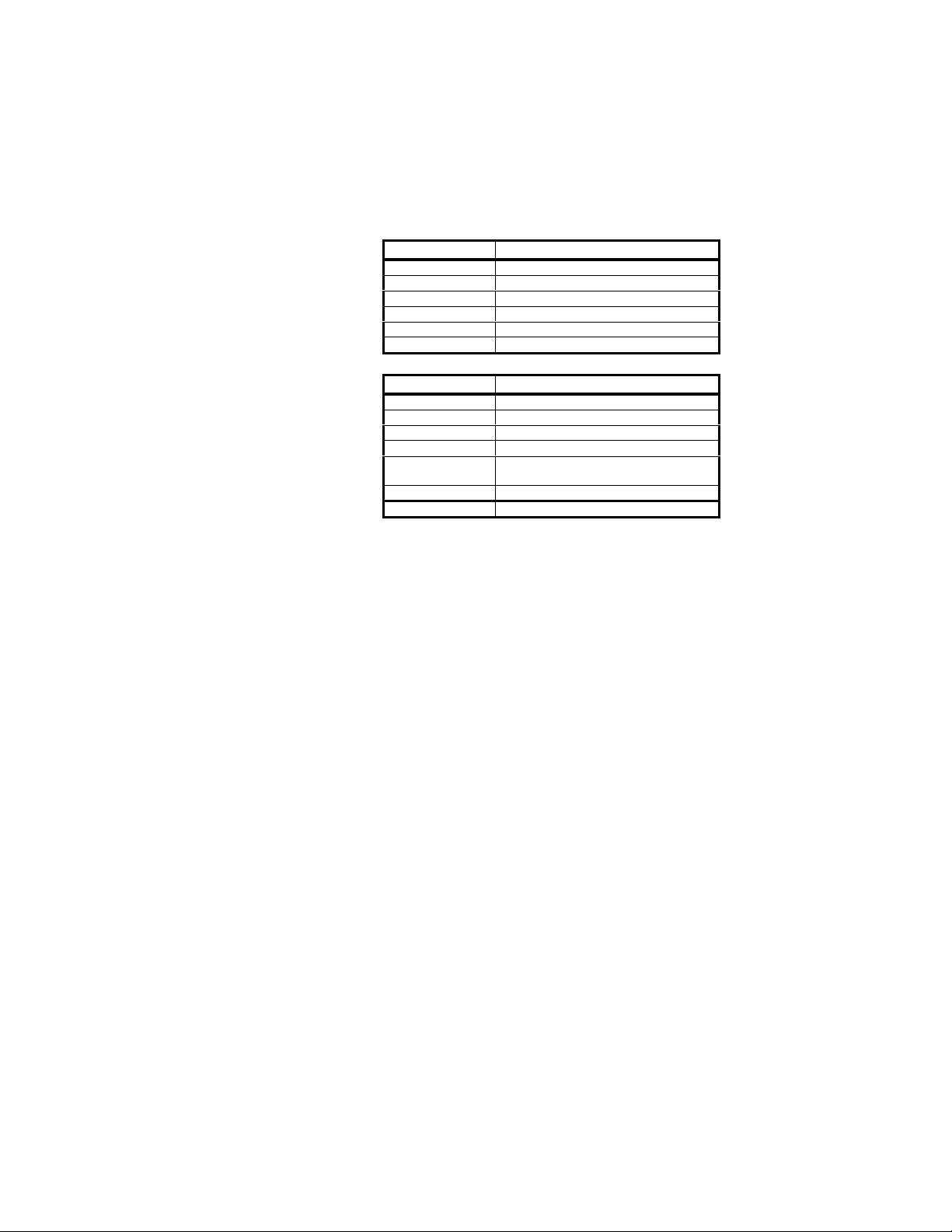
GetChannelOffset( ChannelNumber )
Requests the camera to return the present offset setting for the specified channel. The
offset value is in an 8 bit, straight binary format.
ChannelNumber = 1, 2, or 3
Message Byte Contents
0 $02 - STX
1 $02 - LSB size
2 $00 - MSB size
3 $05 - command byte
4 channel number
5 $?? - checksum
Echo;
Message Byte Contents
0 $02 - STX
1 $04 - LSB size
2 $00 - MSB size
3 $05 - command byte
4 channel number
5 offset
6 $?? - status
7 $?? - checksum
DuncanTech
29
Rev 0.3 – 3/14/02
Page 30
DuncanTech
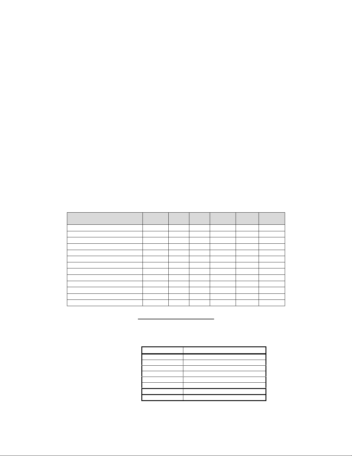
SetIntegrationTime( ChannelNumber, IntegrationTime )
Note: This command title adjusts the length of the time period during which the sensor gathers
light for any given frame. In a conceptual sense, this is often thought of and referred to as
“exposure” control. However, this terminology can be confusing. The specific parameter being
adjusted is the integration time period for the sensor. Parameters for the command include:
ChannelNumber = 1, 2, or 3
IntegrationTime = 1 - 500 (MS2100)
1 - 588 (MS2150)
1 - 1046 (MS3100)
1 - 1046 (DT1100-4)
1 - 1071 (MS2200 – 1024x1)
1 – 1071 (DT1200 – 1024x1)
1 - 2098 (DT1200 – 2048x1)
1 - 1046 (RH1100)
1 - 1046 (RH1200 – 1024x1)
Note: The integration time parameter specifies the number of line periods (i.e. the time required
to read one line of the image) that should elapse for the integration period. Conversion of this
unitless value to an integration time value in seconds is therefore a function of line length (the #
of pixels in a row and the pixel clock rate). Values for the various camera models are as
follows:
Model PixClk
MHz
MS2100 12 30 500 .065 32.5 .065
MS2150 14.07 25 588 .067 39.5 .067
MS3100 (7.5 fps) 14.318 7.59 1046 .125 130.75 .125
MS3100 (10 fps) 18.87 10 1046 .095 99 .095
DT1100-4 (7.5 fps) 14.318 7.59 1046 .125 130.75 .125
DT1100-4 (12 fps) 22.6 12 1046 .079 83 .079
RH1100-4 (7.5 fps) 14.318 7.59 1046 .125 130.75 .125
RH1100-4 (10 fps)
RH1100-4 (12 fps) 22.6 12 1046 .079 83 .079
MS2200 (1024x1) 1 1071 1
DT1200 1 1071 1
RH1200 (1024x1) 1 1071 1
RH2200 (1024x1) 1 1071 1
Fps Max
Cnt
Min
(msec)
Max
(msec)
Incr
(msec)
Note Re: Linescan Cameras
The conversion from line periods to milliseconds is generally not useful for linescan cameras due to the
fact that the clock rate varies depending on the application. Additionally, linescan sensors generally are
run at the maximum integration time in order to maximize the available light.
Message Byte Contents
0 $02 - STX
1 $04 - LSB size
2 $00 - MSB size
3 $14 - command byte
4 channel number
5 Exposure Time - LSB
6 Exposure Time - MSB
7 $?? - checksum
30
Rev 0.3 – 3/14/02
Page 31
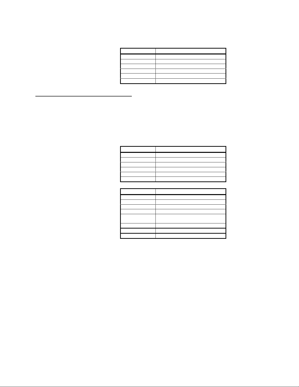
Echo:
Message Byte Contents
GetIntegrationTime( ChannelNumber )
Requests the camera to return the present integration time setting for the
specified channel. The returned value represents the number of scan lines that go to
make up the integration time. To convert this count to msec, multiply the returned value
by the Incr value in the table above.
ChannelNumber = 1, 2, or 3
Message Byte Contents
Echo:
Message Byte Contents
DuncanTech
0 $02 - STX
1 $02 - LSB size
2 $00 - MSB size
3 $14 - command byte
4 status
5 $?? - checksum
0 $02 - STX
1 $02 - LSB size
2 $00 - MSB size
3 $15 - command byte
4 channel number
5 $?? - checksum
0 $02 - STX
1 $05 - LSB size
2 $00 - MSB size
3 $15 - command byte
4 channel number
5 Exposure Time (LSB)
6 Exposure Time (MSB)
7 $?? - status
8 $?? - checksum
31
Rev 0.3 – 3/14/02
Page 32
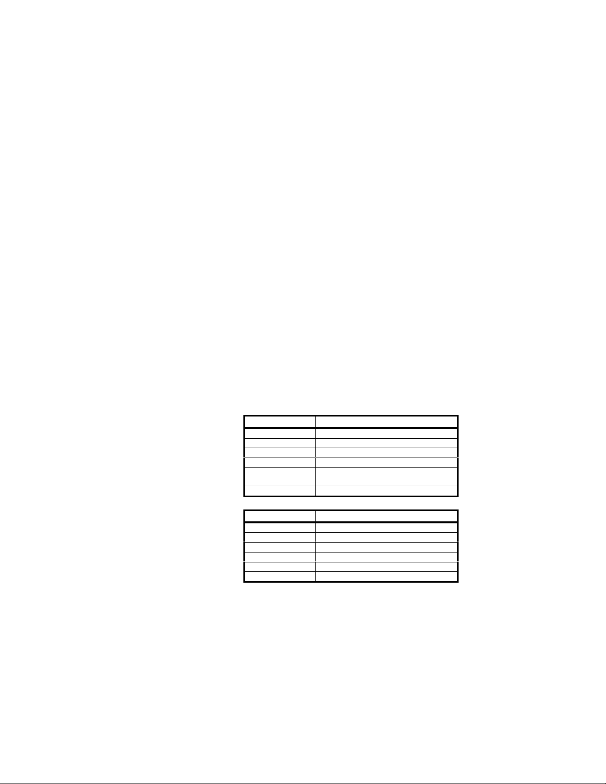
SetTriggerMode()
Sets the camera to one of the supported trigger modes.
Message Byte Structure:
SetTriggerMode()
DuncanTech
LSB Bits 0,1,2 = Area Camera Modes
0 = Video mode
1 = Edge mode
2 = Int & Dump, level mode
3 = Int & Dump, programmable, ganged
4 = Int & Dump, programmable, individual
5-7 = Unused
LSB Bits 0,1,2 = Line Camera Modes
0 = Frame Mode, Free Running
1 = Frame Mode, Triggered
2 = Line Mode, Free Running
3 = Line Mode, Edge Triggered
4 = Line Mode, Int & Dump, Level Controlled
5 = Line Mode, Int & Dump, Programmable
6-7 = Unused
LSB Bit 3 = Trigger Source
0 = BNC
1 = Frame Grabber
LSB Bit 4 = Trigger Polarity
1 = Positive Edge or Level
0 = Negative Edge or Level
Echo:
Message Byte Contents
0 $02 - STX
1 $03 - LSB size
2 $00 - MSB size
3 $16 - command byte
4 Mode - LSB
5 Mode - MSB
6 $?? - checksum
Message Byte Contents
0 $02 - STX
1 $02 - LSB size
2 $00 - MSB size
3 $16 - command byte
4 status
5 $?? - checksum
32
Rev 0.3 – 3/14/02
Page 33
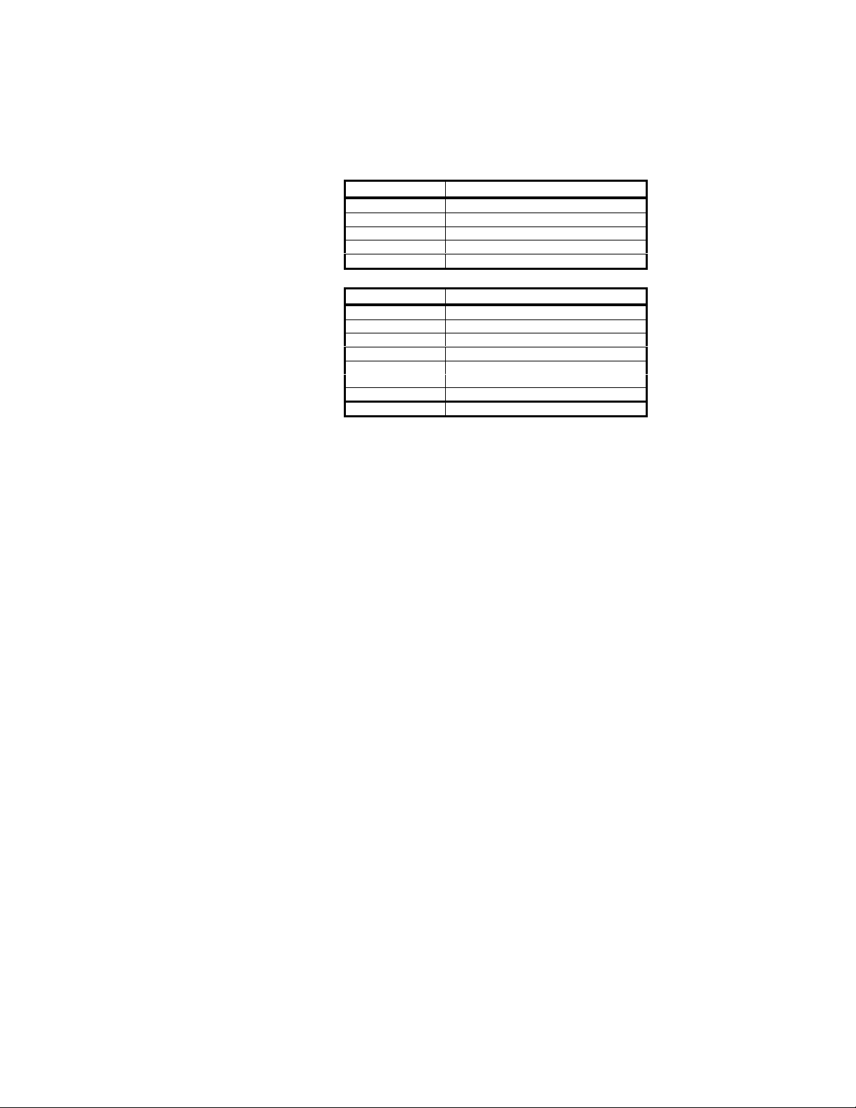
GetTriggerMode()
Requests the camera to return the present trigger mode setting.
DuncanTech
Message Byte Contents
0 $02 - STX
1 $01 - LSB size
2 $00 - MSB size
3 $17 - command byte
4 $?? - checksum
Echo:
Message Byte Contents
0 $02 - STX
1 $04 - LSB size
2 $00 - MSB size
3 $17 - command byte
4 trigger mode (LSB)
5 trigger mode (MSB)
6 $?? - status
7 $?? - checksum
33
Rev 0.3 – 3/14/02
Page 34
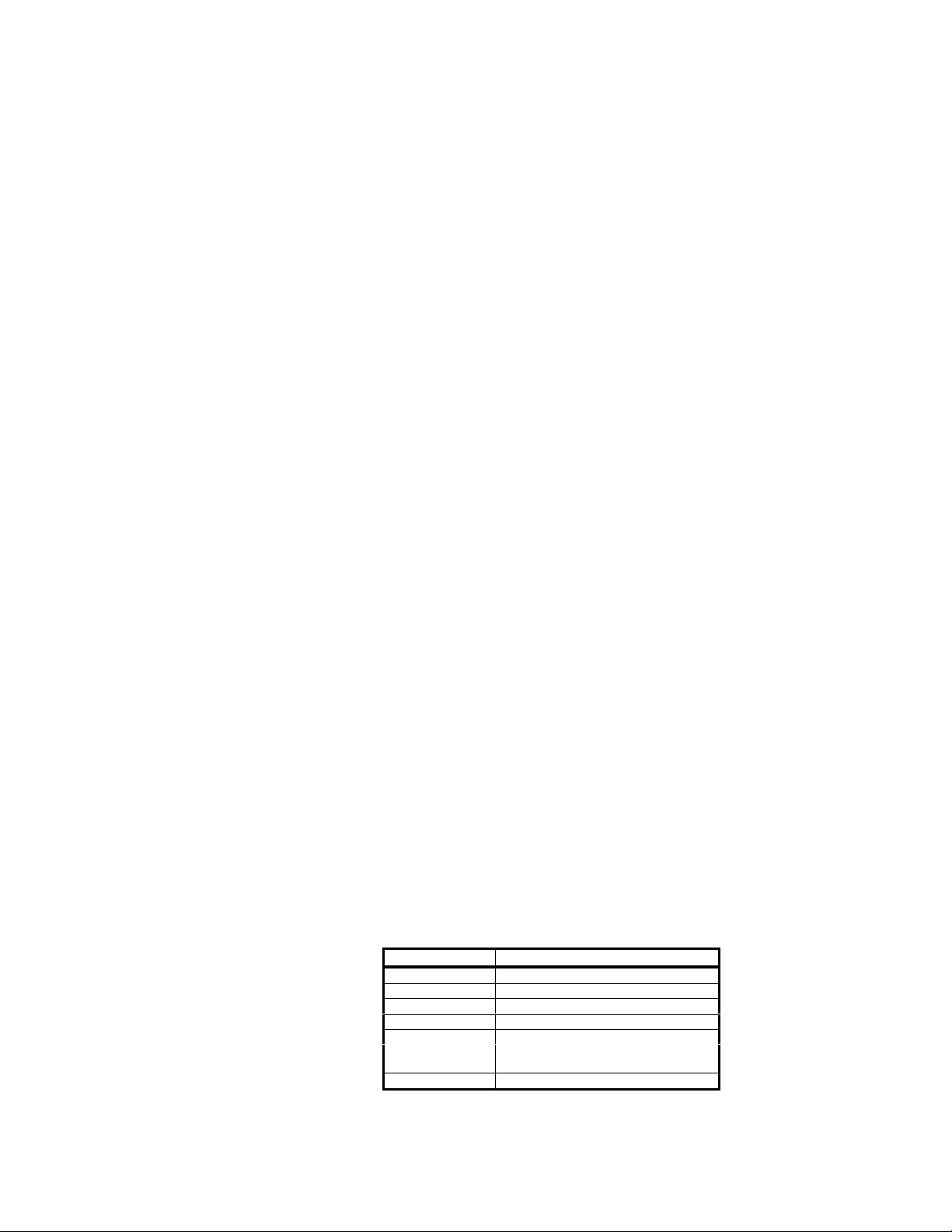
SetOutputMux( Three Byte Value )
Sends a three-byte message to the camera specifying the camera multiplexing
configuration. This determines how the available data from the camera is mapped to the
output ports or taps. The correspondence between Ports and display color plane is a
function of the receiving frame grabber or host circuitry. Typically, the analog video
output is configured such that, Port 0 corresponds to red, Port 1 corresponds to blue,
and Port 2 corresponds to green. However, this mapping can be changed with the
SetVideoMux command. Port four has no meaning for the analog video output.
This command determines which camera image will be directed from to any given digital
output port in the system.
This command also includes the ability to set a digital multiplier for each channel. This
causes the digital pixel value for all the pixels of a given channel to be multiplied by
either one, two, or four (performing a left shift).
Message Byte Structure:
Byte0 Bits;
0,1,2 = Port0 Array Select
(0=Array1
1=Array2
2=Array3
3=Processed Red
4 = Processed Green
5 =Processed Blue
6=Processed Mono
7=Off)
3,4,5 = Port1 Array Select (see Port0 Array Select)
6,7 = Unused
Byte1 Bits;
0,1,2 = Port2 Array Select (see Port0 Array Select)
3,4,5 = Port3 Array Select (see Port0 Array Select)
6 = Unused
7 = Data Resolution
(0 = 8 bits
1 = 10 bits)
Byte2 Bits;
0,1 = Array1 Multiplier (0=X1, 1=X2, 2=X4)
2,3 = Array2 Multiplier
4,5 = Array3 Multiplier
6,7 = Unused
DuncanTech
Message Byte Contents
0 $02 - STX
1 $04 - LSB size
2 $00 - MSB size
3 $1A - command byte
4 Value - Byte0
5 Value - Byte1
6 Value - Byte2
7 $?? - checksum
34
Rev 0.3 – 3/14/02
Page 35
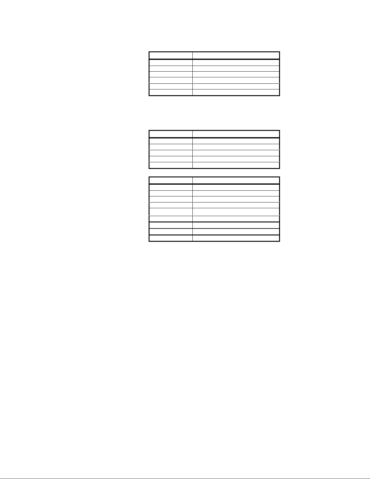
Echo:
GetOutputMux()
Requests the camera to return the present output mux configuration.
DuncanTech
Message Byte Contents
0 $02 - STX
1 $02 - LSB size
2 $00 - MSB size
3 $1A - command byte
4 status
5 $?? - checksum
Message Byte Contents
0 $02 - STX
1 $01 - LSB size
2 $00 - MSB size
3 $1B - command byte
4 $?? - checksum
Echo:
Message Byte Contents
0 $02 - STX
1 $05 - LSB size
2 $00 - MSB size
3 $1B - command byte
4 Value - Byte0
5 Value - Byte1
6 Value - Byte2
7 $?? - status
8 $?? - checksum
35
Rev 0.3 – 3/14/02
Page 36
SetVideoMode(Value)
This command provides a means to configure the optional analog video output. In
cameras that were purchased without the DirectView video option, this command will
return an Unknown Command status from the camera. This command can also be used
to cause the camera to output a color bar pattern for system test and setup.
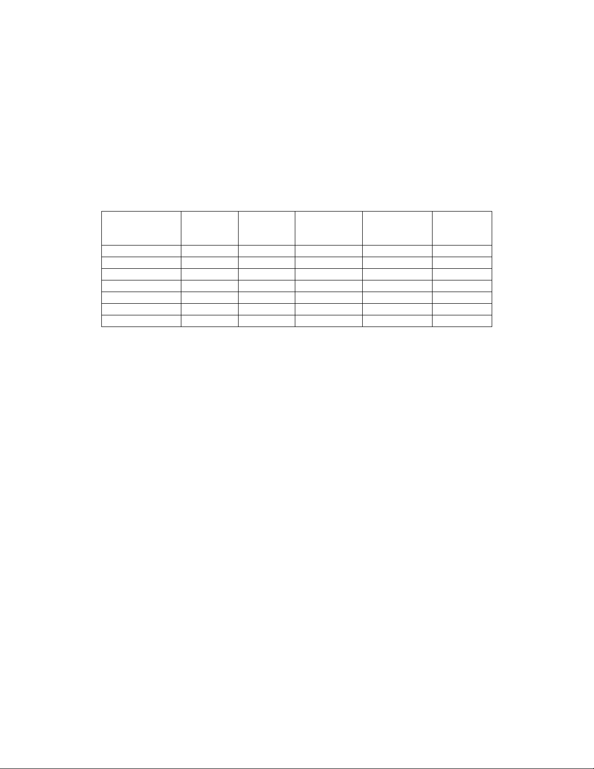
The value passed determines the format that will be used for the video output signal.
Not all modes are valid for all camera models. The table below shows the available
video formats, which ones are valid for each camera model, and the value that should be
passed to set that mode.
DuncanTech
Video Mode MS2100
NTSC Yes Yes Yes Yes Yes
PAL Yes Yes Yes Yes Yes
Interlaced RGB Yes NA NA NA NA
640x480 * Yes Yes Yes Yes Yes
800x600 * NA Yes NA NA NA
1024x768 * NA NA NA NA Yes
1280x1024 * NA NA Yes Yes NA
* - Progressive Scan RGB
Message Byte Structure:
Value = 2 bytes
LSB, Bits 0,1,2 = Mode Select
LSB, Bit 3 = Gamma
LSB, Bit 4,5 = Output
LSB, Bit 6 = unused
LSB, Bit 7 = reserved, must be zero
(656x494)
MS2150
(780x582)
MS3100
(1392x1040)
(See table above)
(0 = no NTSC gamma correction
1 = NTSC gamma correction enabled)
0 = normal video output
1 = color bar pattern output
2-3 = unused
RH1100
(1392x1040)
MS2200
(1024
Line)
MSB, Bits 0,1,2 = PAL mode
0 = B
1 = D
2 = G
3 = H
4 = I
5 = M
6 = N
36
Rev 0.3 – 3/14/02
Page 37
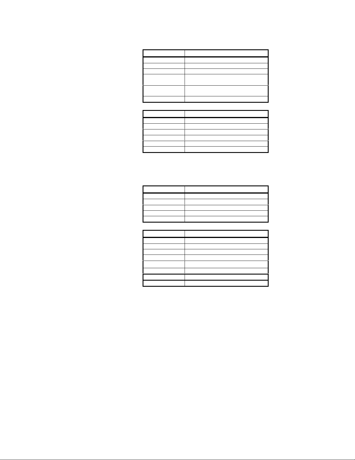
GetVideoMode()
Requests the camera to return the current video mode configuration.
DuncanTech
Message Byte Contents
0 $02 - STX
1 $03 - LSB size
2 $00 - MSB size
$1C - command byte
3
4 Value - LSB
5 Value - MSB
6 $?? - checksum
Echo:
Message Byte Contents
0 $02 - STX
1 $02 - LSB size
2 $00 - MSB size
3 $1C - command byte
4 status
5 $?? - checksum
Message Byte Contents
0 $02 - STX
1 $01 - LSB size
2 $00 - MSB size
3 $1D - command byte
4 $?? - checksum
Echo:
Message Byte Contents
0 $02 - STX
1 $04 - LSB size
2 $00 - MSB size
3 $1D - command byte
4 Value - LSB
5 Value - MSB
6 $?? - status
7 $?? - checksum
37
Rev 0.3 – 3/14/02
Page 38
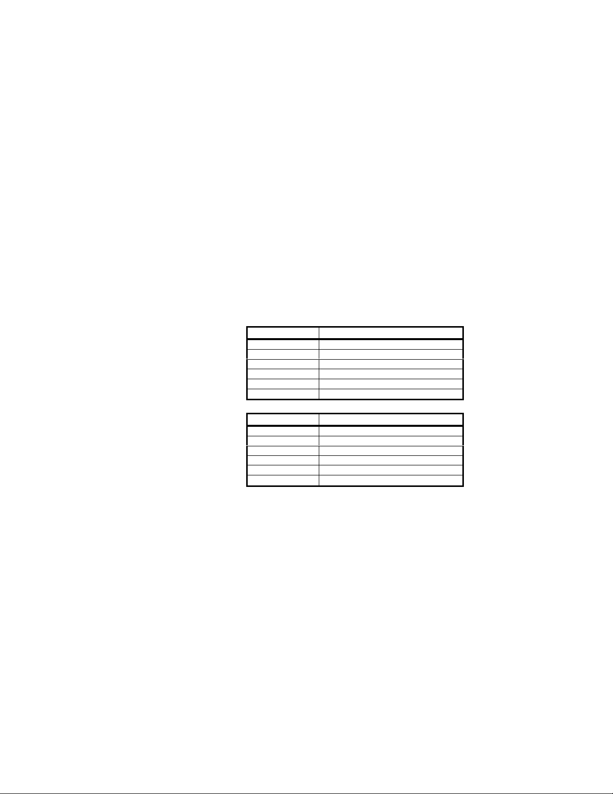
CorrectGain(ChannelNumber)
This command is used for the flat field normalization process in lines scan cameras.
The process reads 16 line scans from the camera and averages them. These average
values are used to adjust individual gain values per pixel relative to the maximum
average pixel value. The function returns the maximum average pixel value for
reference.
This function will have no effect in area scan cameras. It applies gain correction or
resets correction for the specified channel. Argument values for channel number are as
follows:
ChannelNumber = 1 - Perform gain correction for Array 1
DuncanTech
2 – Perform gain correction for Array 2
3 – Perform gain correction for Array 3
4 – Reset gain to 1 for Array 1
5 – Reset gain to 2 for Array 2
6 – Reset gain to 3 for Array 3
7 – Write correction values to non-volatile RAM
(Note – write process takes up to 5 minutes)
Echo:
Message Byte Contents
0 $02 - STX
1 $02 - LSB size
2 $00 - MSB size
3 $38 - command byte
4 channel number
5 $?? - checksum
Message Byte Contents
0 $02 - STX
1 $02 - LSB size
2 $00 - MSB size
3 $38 - command byte
4 status
5 $?? - checksum
38
Rev 0.3 – 3/14/02
Page 39
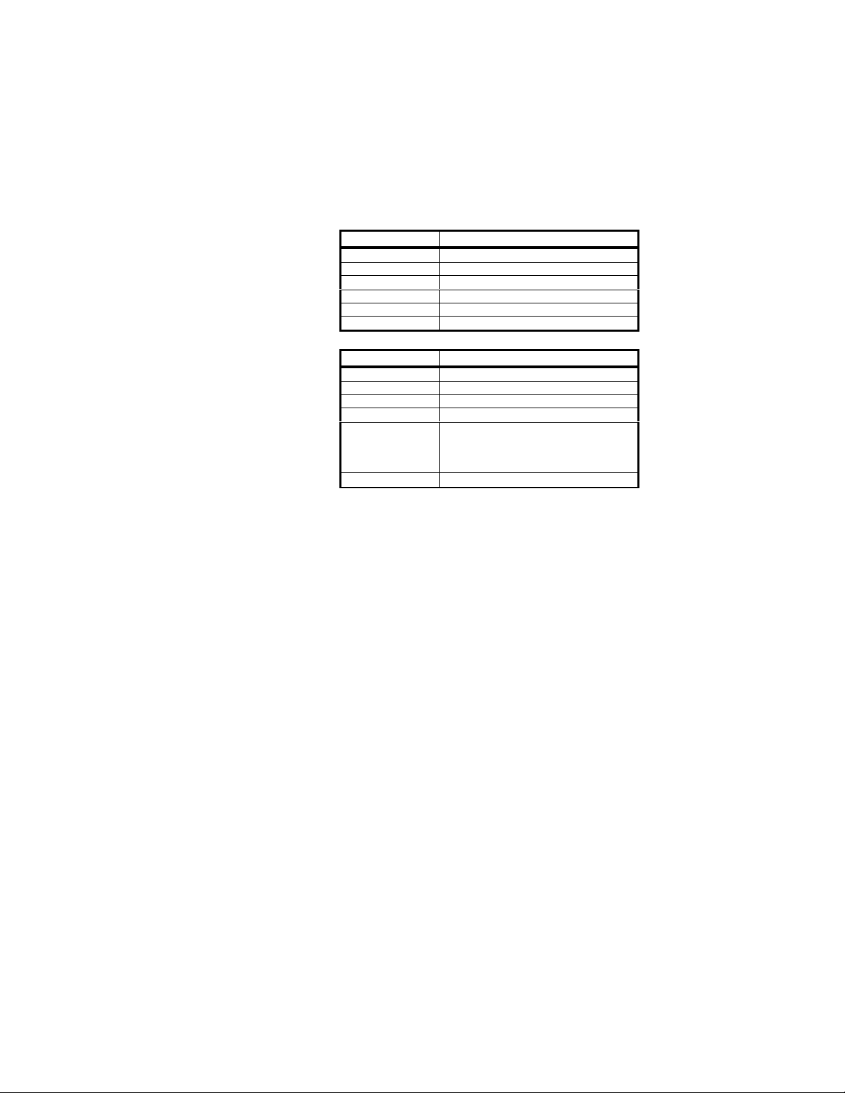
GetGainCorrectionResult(ChannelNumber)
Returns the maximum value of the pixels determined during the gain correction process
for the specified channel.
ChannelNumber = 1 - 3
Message Byte Contents
0 $02 - STX
1 $02 - LSB size
2 $00 - MSB size
3 $39 - command byte
4 channel number
5 $?? - checksum
Echo:
Message Byte Contents
0 $02 - STX
1 $05 - LSB size
2 $00 - MSB size
3 $39 - command byte
4 channel number
5 Maximum Value - Low Byte
6 Maximum Value - High Byte
7 status
8 $?? - checksum
DuncanTech
39
Rev 0.3 – 3/14/02
Page 40
DuncanTech
SetPixelClockRate(Frequency)
Line Scan Cameras Only
Caution: DuncanTech area scan cameras are built for a specified pixel clock rate. Do not use
this command on an area scan camera. Changing the pixel clock rate of area scan models may
cause the camera to malfunction.
This command allows you to request a different pixel clock speed for a linescan camera.
Anytime the pixel clock for the camera is changed, you should power down the camera and then
re-start it. Changing the pixel clock without cycling the power may result in unpredictable
behavior.
Frequency = in integer units of Mhz
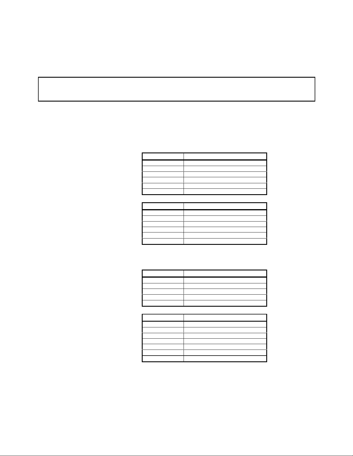
Message Byte Contents
0 $02 - STX
1 $02 - LSB size
2 $00 - MSB size
3 $0A - command byte
4 Frequency
5 $?? - checksum
Echo;
Message Byte Contents
0 $02 - STX
1 $02 - LSB size
2 $00 - MSB size
3 $0A - command byte
4 status
5 $?? - checksum
GetPixelClockRate()
Echo;
Message Byte Contents
0 $02 - STX
1 $01 - LSB size
2 $00 - MSB size
3 $0B - command byte
4 $?? - checksum
Message Byte Contents
0 $02 - STX
1 $03 - LSB size
2 $00 - MSB size
3 $0B - command byte
4 Frequency
5 $?? - status
6 $?? - checksum
40
Rev 0.3 – 3/14/02
Page 41
SetAnalogColorBalance()
This command is used with camera models that utilize a Bayer Pattern Color Filter CCD
sensor. This includes the DT1100, RH1100 with color heads, and MS3100-RGB/CIR.
Each color may be multiplied by a six-bit value corresponding to a scaling of -2dB to
+10Db. Commmand Parameters:
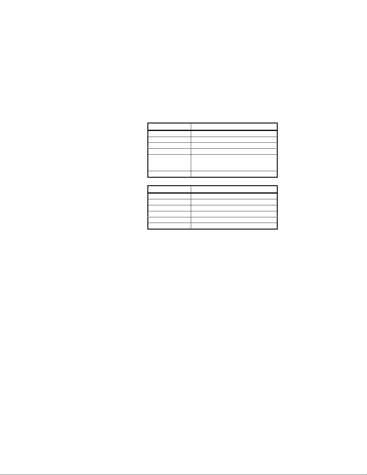
Byte 0 = Red scale factor
Byte 1 = Green scale factor
Byte 2 = Blue scale factor
Echo;
DuncanTech
Message Byte Contents
0 $02 - STX
1 $04 - LSB size
2 $00 - MSB size
3 $30 - command byte
4 Red Scale Factor
5 Green Scale Factor
6 Blue Scale Factor
7 $?? - checksum
Message Byte Contents
0 $02 - STX
1 $02 - LSB size
2 $00 - MSB size
3 $30 - command byte
4 status
5 $?? - checksum
41
Rev 0.3 – 3/14/02
Page 42
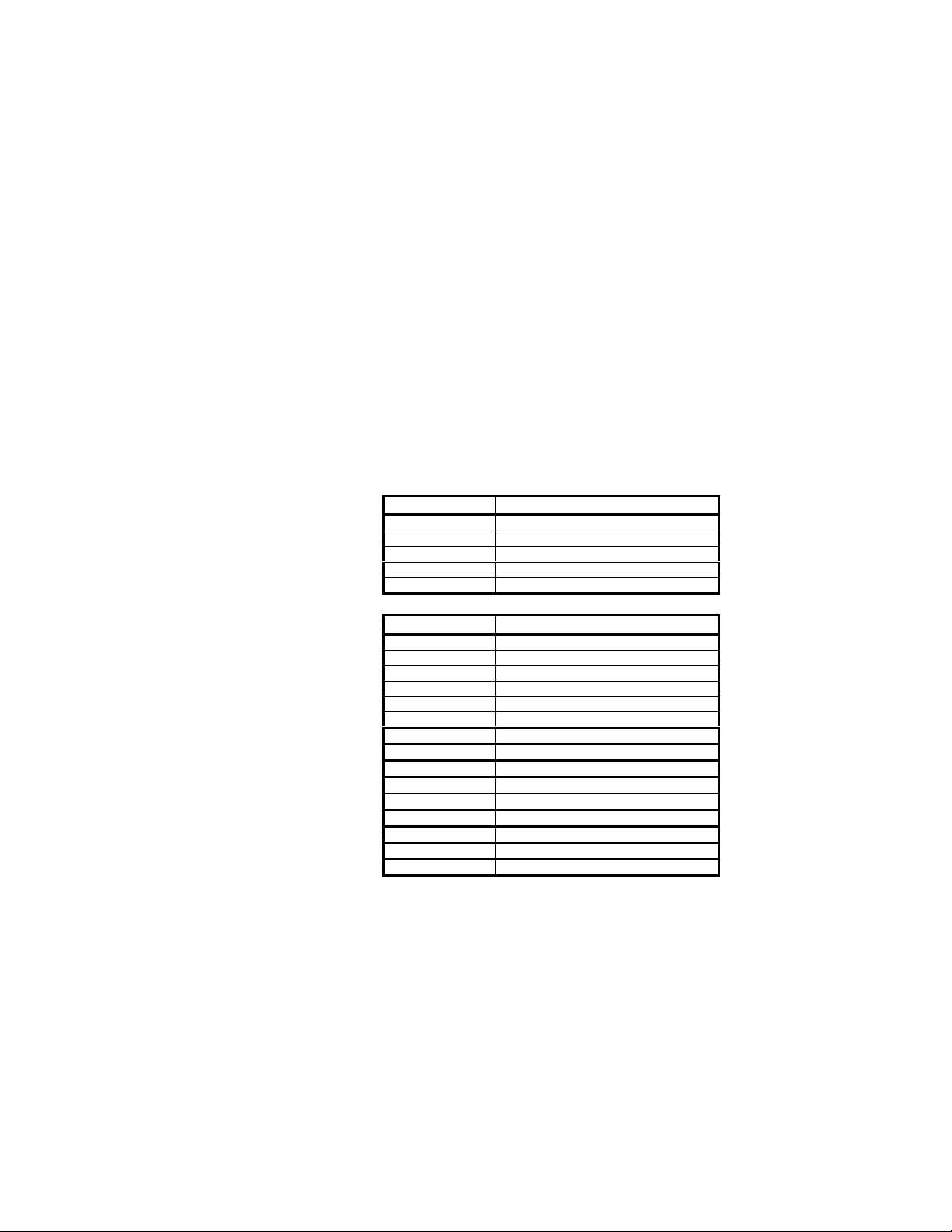
GetAnalogColorBalance()
This command is used with camera models that utilize a Bayer Pattern Color Filter CCD
sensor. This includes the DT1100, RH1100 with color heads, and MS3100-RGB/CIR.
Returns the color balance scale factors for red, green and blue as well as three, 16 bit
values corresponding the average intensity of each color in the color balance
measurement window.
Byte 0 = Red scale factor
Byte 1 = Green scale factor
Byte 2 = Blue scale factor
Byte 3 = Red Intensity LSB
Byte 4 = Red Intensity MSB
Byte 5 = Green Intensity LSB
Byte 6 = Green Intensity MSB
Byte 7 = Blue Intensity LSB
Byte 8 = Blue Intensity MSB
Message Byte Contents
Echo;
Message Byte Contents
DuncanTech
0 $02 - STX
1 $01 - LSB size
2 $00 - MSB size
3 $31 - command byte
4 $?? - checksum
0 $02 - STX
1 $0b - LSB size
2 $00 - MSB size
3 $31 - command byte
4 Red scale factor
5 Green scale factor
6 Blue scale factor
7 Red Intensity LSB
8 Red Intensity MSB
9 Green Intensity LSB
10 Green Intensity MSB
11 Blue Intensity LSB
12 Blue Intensity MSB
13 $?? - status
14 $?? - checksum
42
Rev 0.3 – 3/14/02
Page 43
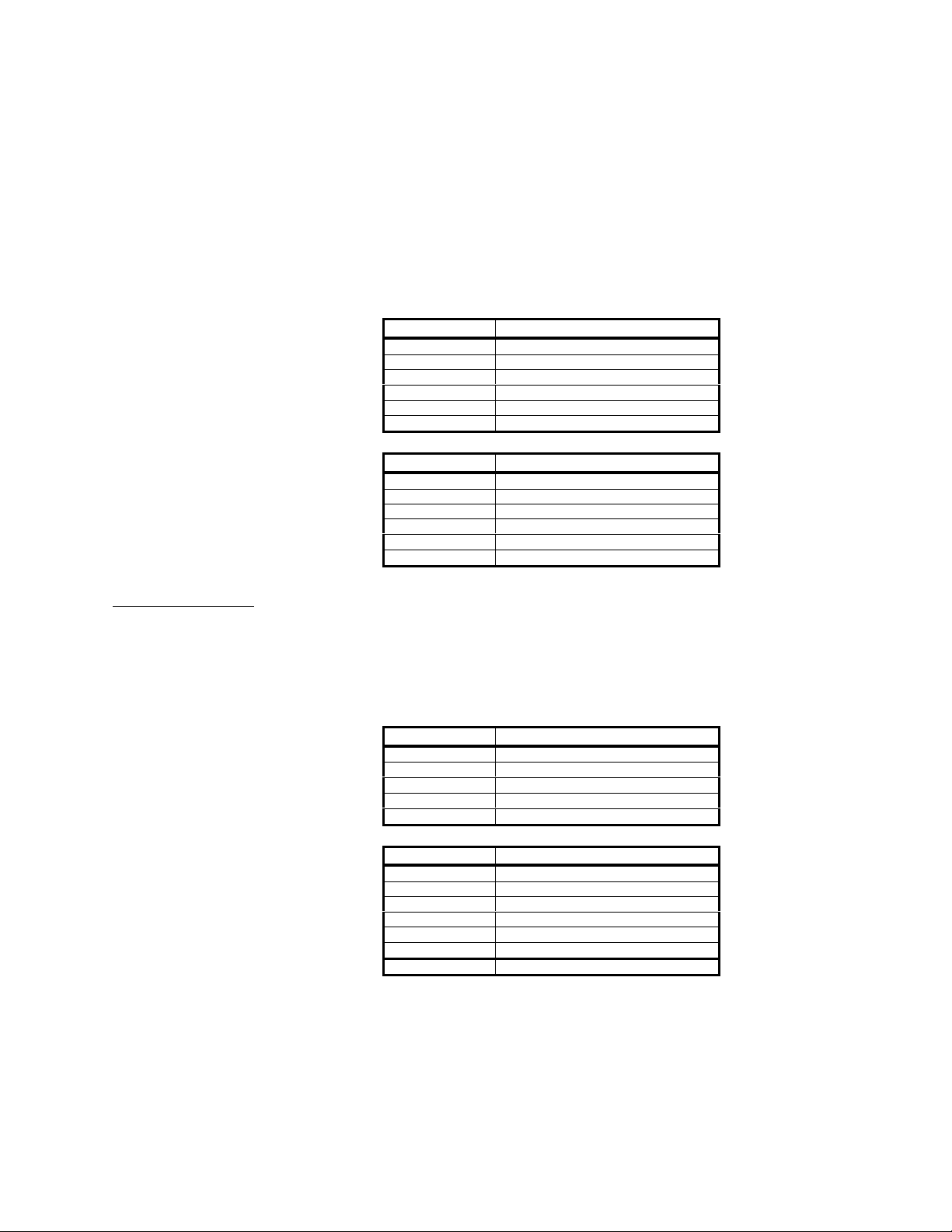
SetZoomFactor()
This command is only available in cameras with DirectView Analog Video. For cameras
with DirectView, availability of this command will depend upon the rev level of the
hardware.
DuncanTech
Sets X1, X2 or X4 zoom factor for video display
Byte 0 = ZoomFactor;
1 = X1
2 = X2
4 = X4
Message Byte Contents
0 $02 - STX
1 $02 - LSB size
2 $00 - MSB size
3 $32 - command byte
4 ZoomFactor
5 $?? - checksum
Echo;
Message Byte Contents
0 $02 - STX
1 $02 - LSB size
2 $00 - MSB size
3 $32 - command byte
4 status
5 $?? - checksum
GetZoom Factor()
Returns the video zoom factor
Byte 0 = ZoomFactor;
1 = X1
2 = X2
4 = X4
Message Byte Contents
0 $02 - STX
1 $01 - LSB size
2 $00 - MSB size
3 $33 - command byte
4 $?? - checksum
Echo;
Message Byte Contents
0 $02 - STX
1 $03 - LSB size
2 $00 - MSB size
3 $33 - command byte
4 ZoomFactor
5 $?? - status
6 $?? - checksum
43
Rev 0.3 – 3/14/02
Page 44
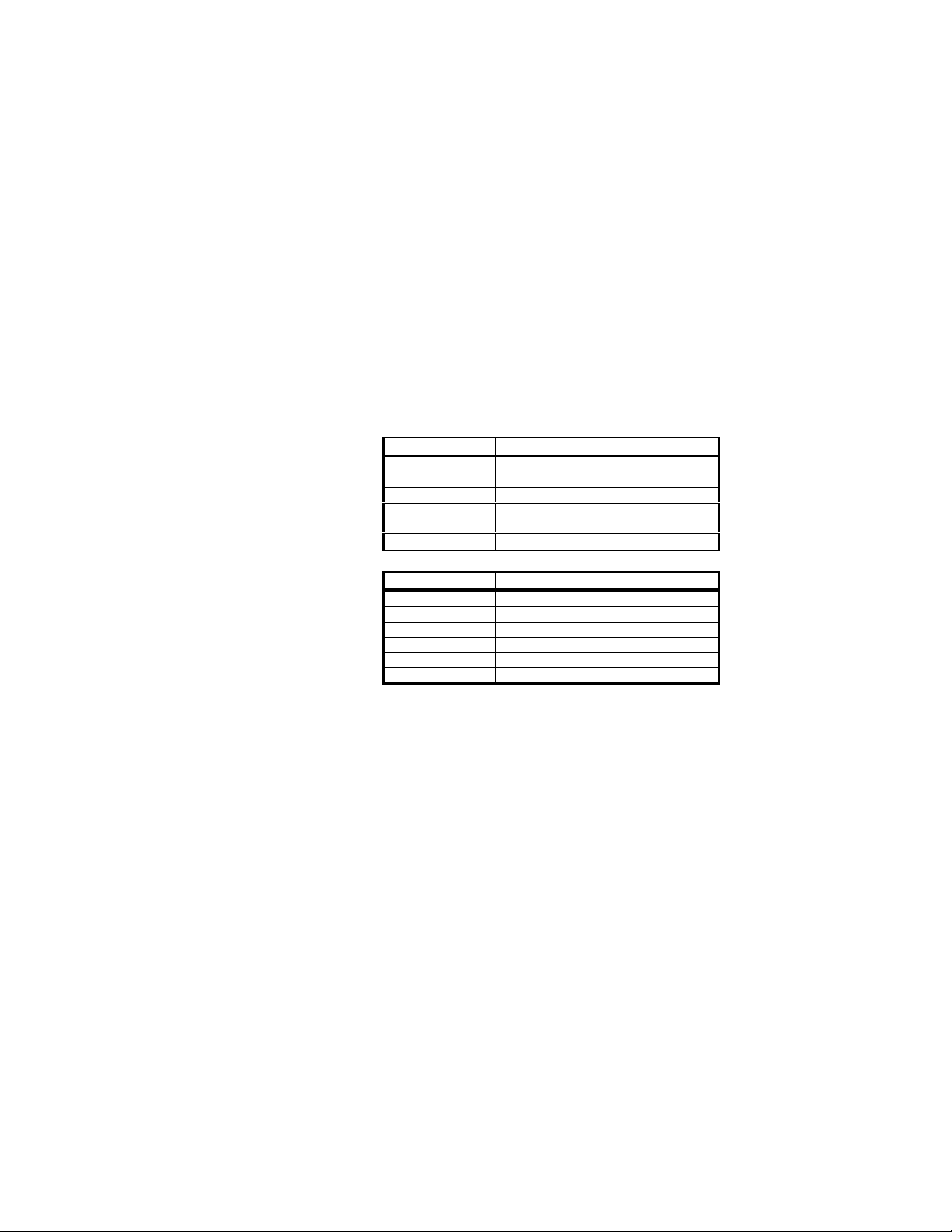
SetVideoMux()
Note: This command should be used with caution. It should only be necessary to change
these settings when the color plane mapping between the digital output ports and the
analog video ports do not correspond, resulting in color differences between the analog
video display and the digital display. Some framegrabbers require this correction.
DuncanTech
Sets Video Card Multiplexer Configuration
Byte 0 = MuxConfiguration
Bits;
0 - 1 = Red Output Selection
0 = Port0
1 = Port1
2 = Port2
3 = Port3
2 - 3 = Green Output Selection
4 - 5 = Blue Output Selection
Message Byte Contents
0 $02 - STX
1 $02 - LSB size
2 $00 - MSB size
3 $3d - command byte
4 MuxConfiguration
5 $?? - checksum
Echo;
Message Byte Contents
0 $02 - STX
1 $02 - LSB size
2 $00 - MSB size
3 $3d - command byte
4 status
5 $?? - checksum
44
Rev 0.3 – 3/14/02
Page 45
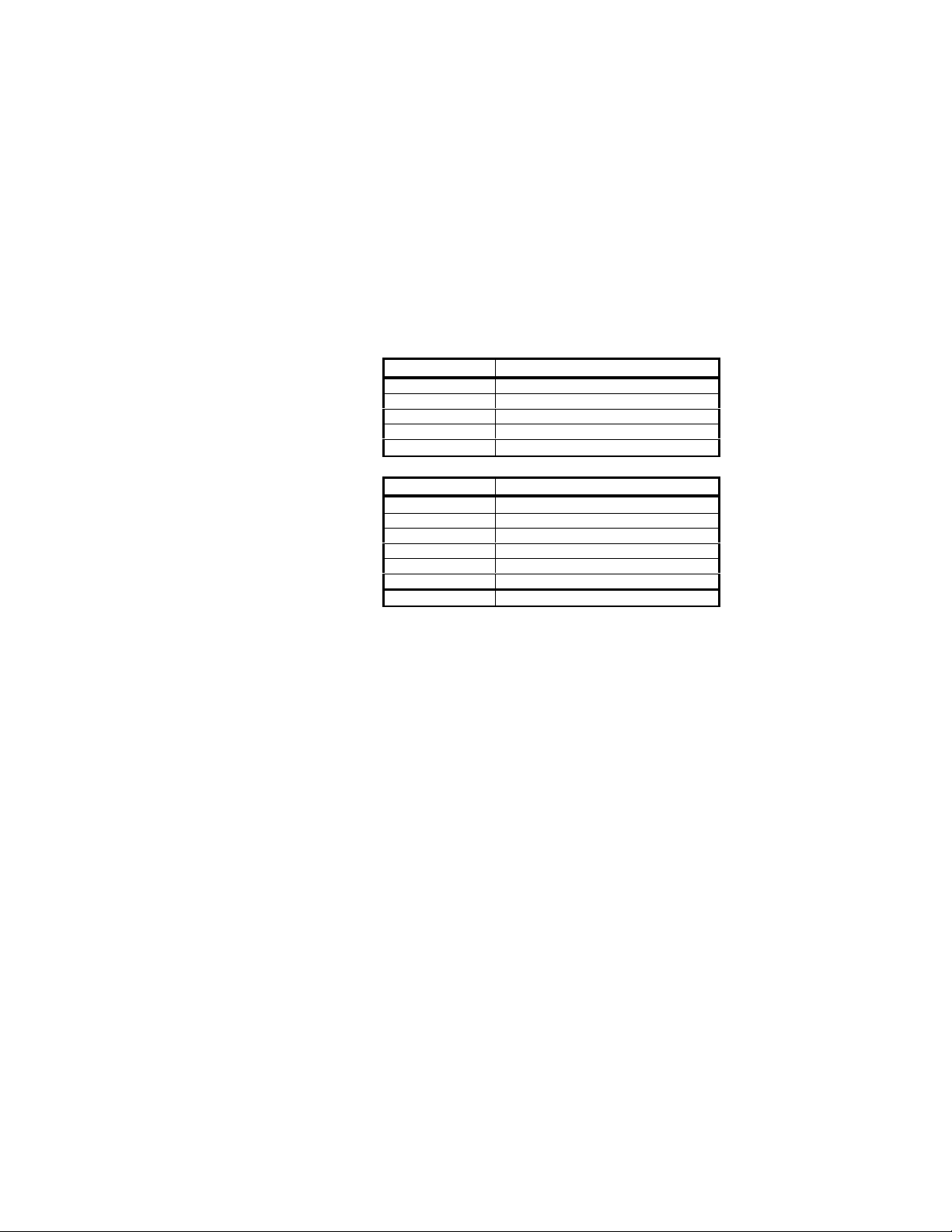
GetVideoMux()
DuncanTech
Gets Video Card Multiplexer Configuration
Byte 0 = MuxConfiguration
Bits;
0 - 1 = Red Output Selection
0 = Port0
1 = Port1
2 = Port2
3 = Port3
2 - 3 = Green Output Selection
4 - 5 = Blue Output Selection
Message Byte Contents
0 $02 - STX
1 $01 - LSB size
2 $00 - MSB size
3 $3e - command byte
4 $?? - checksum
Echo;
Message Byte Contents
0 $02 - STX
1 $03 - LSB size
2 $00 - MSB size
3 $3e - command byte
4 MuxConfiguration
5 $?? - status
6 $?? - checksum
45
Rev 0.3 – 3/14/02
Page 46
SetCrosshairs()
Sets Crosshairs in digital image data Byte 0 = CrosshairControl
DuncanTech
Bit 0 = On/Off;
0 = Off
1 = On
Message Byte Contents
0 $02 - STX
1 $02 - LSB size
2 $00 - MSB size
3 $3f - command byte
4 CrosshairControl
5 $?? - checksum
Echo;
Message Byte Contents
0 $02 - STX
1 $02 - LSB size
2 $00 - MSB size
3 $3f - command byte
4 status
5 $?? - checksum
GetCrosshairs ()
Gets Crosshair Status
Byte 0 = CrosshairControl
Bit 0 = On/Off;
0 = Off
1 = On
Message Byte Contents
0 $02 - STX
1 $01 - LSB size
2 $00 - MSB size
3 $40 - command byte
4 $?? - checksum
Echo;
Message Byte Contents
0 $02 - STX
1 $03 - LSB size
2 $00 - MSB size
3 $40 - command byte
4 CrosshairControl
5 $?? - status
6 $?? - checksum
46
Rev 0.3 – 3/14/02
Page 47
SetZoomFactor()
This command is only available in cameras with DirectView Analog Video. For cameras
with DirectView, availability of this command will depend upon the rev level of the
hardware.
DuncanTech
Sets X1, X2 or X4 zoom factor for video display
Byte 0 = ZoomFactor;
1 = X1
2 = X2
4 = X4
Message Byte Contents
0 $02 - STX
1 $02 - LSB size
2 $00 - MSB size
3 $32 - command byte
4 ZoomFactor
5 $?? - checksum
Echo;
Message Byte Contents
0 $02 - STX
1 $02 - LSB size
2 $00 - MSB size
3 $32 - command byte
4 status
5 $?? - checksum
GetZoom Factor()
Returns the video zoom factor
Byte 0 = ZoomFactor;
1 = X1
2 = X2
4 = X4
Message Byte Contents
0 $02 - STX
1 $01 - LSB size
2 $00 - MSB size
3 $33 - command byte
4 $?? - checksum
Echo;
Message Byte Contents
0 $02 - STX
1 $03 - LSB size
2 $00 - MSB size
3 $33 - command byte
4 ZoomFactor
5 $?? - status
6 $?? - checksum
47
Rev 0.3 – 3/14/02
Page 48
GetAllAverages()
Returns average value in display window for six images, three raw arrays and 3
bayer demultiplexed. Average values are 8 bits.
DuncanTech
Message Byte Contents
0 $02 - STX
1 $01 - LSB size
2 $00 - MSB size
3 $41 - command byte
4 $?? - checksum
Echo;
Message Byte Contents
0 $02 - STX
1 $08 - LSB size
2 $00 - MSB size
3 $41 - command byte
4 Array 1 Average
5 Array 2 Average
6 Array 3 Average
7 Bayer Red Average
8 Bayer Green Average
9 Bayer Blue Average
10 $?? - status
11 $?? - checksum
48
Rev 0.3 – 3/14/02
Page 49
GetRemoteHeadConfiguration()
Used for remote head cameras only (RH1100 or RH1200). Returns configuration
information for the three remote camera heads.
Byte 0 = HeadConfiguration;
Bits 0,1;
Head 1 Configuration;
0 = None
1 = Monochrome
2 = Color (Bayer)
3 = Unused
Bits 2,3;
Head 2 Configuration;
Bits 4,5;
Head 3 Configuration;
Bits 6,7; Unused
Message Byte Contents
0 $02 - STX
1 $01 - LSB size
2 $00 - MSB size
3 $42 - command byte
4 $?? - checksum
Echo;
Message Byte Contents
0 $02 - STX
1 $03 - LSB size
2 $00 - MSB size
3 $42 - command byte
4 HeadConfiguration
5 $?? - status
6 $?? - checksum
DuncanTech
49
Rev 0.3 – 3/14/02
Page 50
SetBayerMux()
Used only with RH1100 Remote Head Area Scan cameras only. Specifies which
head on the camera is to be used as the input source for the camera’s Bayer
Color Interpolator engine. Command Parameter:
DuncanTech
Byte 0 = MuxConfiguration
0 = Array 1 as Input
1 = Array 2 as Input
2 = Array 3 as Input
Message Byte Contents
0 $02 - STX
1 $02 - LSB size
2 $00 - MSB size
3 $43 - command byte
4 MuxConfiguration
5 $?? - checksum
Echo;
Message Byte Contents
0 $02 - STX
1 $02 - LSB size
2 $00 - MSB size
3 $43 - command byte
4 status
5 $?? - checksum
GetBayerMux()
Used only with RH1100 Remote Head Area Scan cameras. Queries the camera
to get which head is presently assigned as input to the Bayer Color Interpolator
engine. Command Parameter:
Byte 0 = MuxConfiguration
0 = Array 1 as Input
1 = Array 2 as Input
2 = Array 3 as Input
Message Byte Contents
0 $02 - STX
1 $01 - LSB size
2 $00 - MSB size
3 $44 - command byte
4 $?? - checksum
Echo;
Message Byte Contents
0 $02 - STX
1 $03 - LSB size
2 $00 - MSB size
3 $44 - command byte
4 MuxConfiguration
5 $?? - status
6 $?? - checksum
50
Rev 0.3 – 3/14/02
 Loading...