

Page 1

Owners Manual
Head Office:
P.O. Box 2018
Hilton Highway, Washdyke
Timaru, New Zealand
Telephone (03) 688 2029
Facsimile (03) 688 2821
Australian Branch:
4B Silverton Close
Laverton North 3026
Melbourne, Australia
Telephone (03) 9314-9666
Facsimile (03) 9314-6810
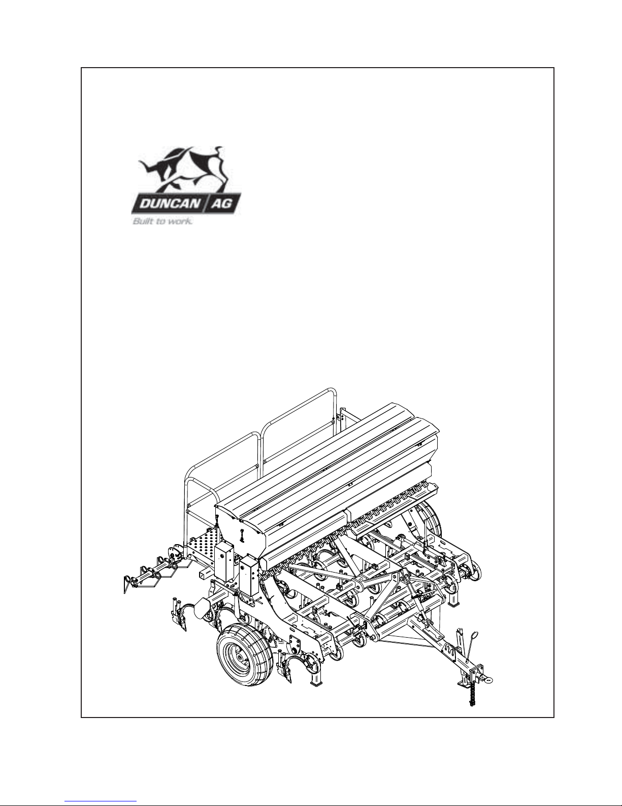
Renovator TFD 3m & 3.5m
ORIGINAL INSTRUCTIONS
Pt. No. 67415
Issue 0517
Page 2

ii
Introduction . . . . . . . . . . . . . . . . . . . . . . . . . . . . . . . . . . . . . . 2
Acquisition & Warranty . . . . . . . . . . . . . . . . . . . . . . . . . . . . . . . . . . . . . . 2
Disclaimer . . . . . . . . . . . . . . . . . . . . . . . . . . . . . . . . . . . . . . 2
Description of Machine Working Principle. . . . . . . . . . . . . . . . . . . . . . . 3
Dimensions & Capacities . . . . . . . . . . . . . . . . . . . . . . . . . . . . . . . . . . . . . . 5
SAFETY - General Safety Symbols on Machine . . . . . . . . . . . . . . 6
Operator Safety . . . . . . . . . . . . . . . . . . . . . . . . 7
Be Prepared for Emergencies . . . . . . . . . . . . . 7
Appropriate Dress . . . . . . . . . . . . . . . . . . . . . . 8
Transport This Machine Safely . . . . . . . . . . . . 8
Handle Agricultural Chemicals Safely . . . . . . . 9
Avoid High Pressure Fluids . . . . . . . . . . . . . . . 9
Safe Work Practices . . . . . . . . . . . . . . . . . . . . 9
Practise Safe Maintenance . . . . . . . . . . . . . . . 10
SAFETY - Machine Specific Hazard Points . . . . . . . . . . . . . . . . . . . . . . . . . 11
Safety Decals & Safety Guards. . . . . . . . . . . . 13
Transport . . . . . . . . . . . . . . . . . . . . . . . . . . . . . . . . . . . . . . 14
Operation . . . . . . . . . . . . . . . . . . . . . . . . . . . . . . . . . . . . . . 15
Read Before Calibration Setting Seeder Shutter Slides. . . . . . . . . . . . . 18
Bottom Flap Settings . . . . . . . . . . . . . . . . . . . . 18
Sowing Fine Seeds . . . . . . . . . . . . . . . . . . . . . 18
General Controls & Main Operating Screen . . 19
Priming Switch Buttons . . . . . . . . . . . . . . . . . . 20
Power On Routine . . . . . . . . . . . . . . . . . . . . . . 21
Main Operating Screen . . . . . . . . . . . . . . . . . . 22
Calibration Procedures . . . . . . . . . . . . . . . . . . 24
Calibration Chart, Default Calibration Factors. 28
Maintenance & Care General . . . . . . . . . . . . . . . . . . . . . . . . . . . . . . 30
Lubrication Instructions . . . . . . . . . . . . . . . . . . 31
Maintenance Schedule . . . . . . . . . . . . . . . . . . 32
Storage . . . . . . . . . . . . . . . . . . . . . . . . . . . . . . 33
Maintenance Notes . . . . . . . . . . . . . . . . . . . . . 34
Parts List Complete Assembly . . . . . . . . . . . . . . . . . . . . 36
Mainframe & Drawbar . . . . . . . . . . . . . . . . . . . 38
Wheel Leg . . . . . . . . . . . . . . . . . . . . . . . . . . . . 42
Wheel Hydraulics. . . . . . . . . . . . . . . . . . . . . . . 44
Adjustable Toolbars . . . . . . . . . . . . . . . . . . . . . 46
Fixed Toolbars . . . . . . . . . . . . . . . . . . . . . . . . . 50
Tine, Boot & Point . . . . . . . . . . . . . . . . . . . . . . 52
Hose Supports. . . . . . . . . . . . . . . . . . . . . . . . . 54
Footboard, Ladder & Handrail. . . . . . . . . . . . . 56
Dual Seedbox Assembly . . . . . . . . . . . . . . . . . 60
Agitator Shaft Assembly . . . . . . . . . . . . . . . . . 64
Renovator TFD Contents
Page
Page 3

1
Pt. No. 67415
Issue 0517
Parts List (continued)
Gearmotor Drives Front/Rear . . . . . . . . . . . . . 67
Electric Drive . . . . . . . . . . . . . . . . . . . . . . . . . . 70
Rear Tow Hitch . . . . . . . . . . . . . . . . . . . . . . . . 76
Tine Harrow . . . . . . . . . . . . . . . . . . . . . . . . . . . 78
Uni-Roller. . . . . . . . . . . . . . . . . . . . . . . . . . . . . 80
Electric Drive (detailed manual) Electric Drive detailed operation and setup . . 83
Renovator TFD Contents (continued)
Page
Page 4

2
Introduction
Acquisition & Warranty
On delivery of your new Duncan Renovator TFD please
check that the machine is not damaged. In cases of shipping
damage, please ask your dealer to arrange for the appropriate
claim to be lodged immediately. Assemble any parts supplied
loose and inspect your machine with the aid of this manual to
familiarise yourself with its features. If you have any queries
ask your dealer straight away. The machine is covered by our
12 month warranty on faulty parts, subject to normal use.
Record below the serial number of your machine and keep
it in a secure place to help trace the machine and assist
us when you order parts.
The Owner’s Manual
Your new Duncan Renovator TFD will give long and efficient
service if given normal care and operated properly.
This owner’s manual is provided so that you can become
thoroughly familiar with the design of the machine and to
furnish information on correct operation, adjustment and
maintenance. Only persons well acquainted with these
guidelines should be allowed to use the equipment.
A separate illustrated parts section has been provided so that
if any parts are required your dealer will be able to supply
them by reference to part numbers.
The manual is considered as part of your machine and must
remain with the machine when it is sold.
Right and left hand references in this manual are
determined by standing behind the machine and facing in
the direction of travel.
Model: . . . . . . . . . . . . . . . . . . . . . . . . . . . . . . . . . . . . . .
Serial No:. . . . . . . . . . . . . . . . . . . . . . . . . . . . . . . . . . .
Owner:. . . . . . . . . . . . . . . . . . . . . . . . . . . . . . . . . . . . . .
. . . . . . . . . . . . . . . . . . . . . . . . . . . . . . . . . . . . . . . . . . . . .
. . . . . . . . . . . . . . . . . . . . . . . . . . . . . . . . . . . . . . . . . . . . .
Delivery Date:. . . . . . . . . . . . . . . . . . . . . . . . . . . . . . .
Dealer:. . . . . . . . . . . . . . . . . . . . . . . . . . . . . . . . . . . . . .
. . . . . . . . . . . . . . . . . . . . . . . . . . . . . . . . . . . . . . . . . . . . .
. . . . . . . . . . . . . . . . . . . . . . . . . . . . . . . . . . . . . . . . . . . . .
Disclaimer
Every effort has been made to
ensure that the information in this
manual was accurate and up to
date at the time of going to press.
Clough Agriculture reserves the
right to make subsequent changes
to the machine, where necessary,
without notification.
The Company will not be
responsible for any damage or
consequential loss arising out of
misinterpretation or failure to follow
recommended procedures. Nor will
it be liable for any damage caused
by or arising out of modification or
misuse of its product.
The owner has a responsibility to
protect himself and others by
observing all safety information
and by ensuring all operators are
well acquainted with the safety
information, trained in the correct
use of the machine and applying
safe work practices.
This Document contains the Original
Operating Instructions for this machine
and are verified by the Manufacturer,
Signed:...........................................
Product Development Manager
Page 5
3
Pt. No. 67415
Issue 0517
Description of Machine
The Duncan Renovator TFD is an S-tine drill with
narrow points. The box is mounted on a robust frame
accommodating large diameter tyres. The ground
engaging components are controlled by a hydraulic
ram system, giving ample control on ground pressure,
good transport clearance and contour following ability.
Sowing depth is controlled by adjusting the hydraulic
rams. Optionally, the angle of the points are adjustable
via rotating tool bars for optimum ground following and
penetration.
The quality European type peg roller seeder system
handles all seeds from turnip and rape through to peas
and maize. The seeder drive is electric via a reduction
gearbox to the seeder shaft. Ground speed is sensed via
ground radar with seed rates controlled proportionally to
ground speed. Seeding ceases automatically when the
machine is raised into the transport position.
Working Principle
The seeder drive, pegged seed rollers and seeder flaps
are set to give the desired seed rate. The S-tine and
narrow point, create the seed bed. Seed flows down the
flexible tubes between seeder and boot units, and drops
into the prepared seed bed.
Renovator TFD
Page 6

4
Page 7
5
Pt. No. 67415
Issue 0517
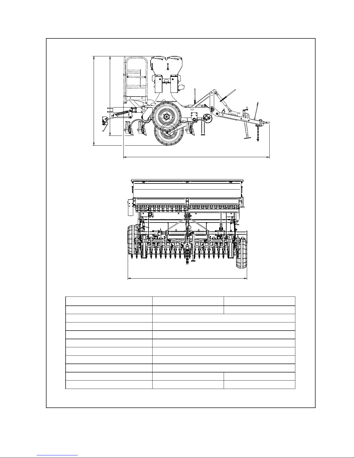
Dimensions & Capacities 24Run 28Run
Width (over wheels /mm) 3100 3600
Working Height (mm) 2060
Transport Height (mm) 2320
Overall Length (mm) 3790
Tyre Size 10.0/75-15.3 (18 ply AW702)
Recommended Tyre Pressure 7 Bar (101psi)
Maximum speed (km/hr) 40 km/hr
Row Spacing (mm) 125
Effective Sowing Width (mm) 3000 3500
Box Capacity (litres per box) 500 600
‘Renovator TFD’ Dimensions & Capacities
:,'7+29(5:+((/6
Page 8

6
Do not ride or allow passengers on the machine.
Under no circumstances are passengers to be permitted
on the machine while it is in operation or being transported.
Any footboards and/or footsteps are provided solely for the
purpose of preparing the machine for use.
Keep clothing and body extremities well clear of pinch
points while the machine is operating (seeding or
calibrating). Keep well clear of moving parts at all times.
These signs typically occur wherever trapping points exist.
These include drive chains, sprockets, shafts, wheels, discs,
pivot points, etc. Guards are provided with the machine
for safety reasons (where practical without compromising
machine performance). Ensure these are always fitted
during operation.
Always exercise extreme caution in the vicinity of sharp
edges and points.
Where possible guards are provided with the machine
for safety reasons (where practical without compromising
machine performance). Ensure these are always fitted
during operation.
Footboards, footsteps, drawbars and other machine
surfaces may be slippery when wet.
Apply extra caution in wet conditions and in the early
morning when surfaces are wet.
Keep Clear. (It is dangerous to be in this area when the
machine is operating.)
!
ATTENTION
On the machine important safety information is indicated by these symbols.
These highlight general safety aspects in regard to the machine rather than specific hazards.
‘Renovator TFD’ Safety
Page 9
7
Pt. No. 67415
Issue 0517
SAFETY - General
This section of the manual offers general guidelines
for the safe operation of machinery. It does not replace
local safety regulations.
These guidelines were current at
the time of publication, but may be superseded by later
regulations.
Clough Agriculture has made every effort to highlight all
risks to personnel or property. Owners and operators have
a responsibility to exercise care and safe work practices at
all times in the vicinity of the machine.
Owners are advised to keep up to date on safety issues
and to communicate these to all users of the machine.
Contact the Occupational Safety and Health Service
(OSH) for further information about general safety aspects.
If you have safety concerns specifically related to this
machine, contact your dealer immediately.
Operator Safety
Read this manual carefully before operating new
equipment. Learn how to use this machine safely.
Be thoroughly familiar with the controls and the proper use
of the equipment before using it.
Take careful note of all safety instructions both in this
manual and on the machine itself. Failure to comply with
instructions could result in personal injury and/or damage
to the machine.
Replace missing or damaged safety signs on the machine
and ensure that these remain clearly visible.
It is the owner’s responsibility to ensure that anyone
who operates, adjusts, lubricates, maintains, cleans
or uses the machine in any way has had suitable
instruction and is familiar with the information in this
manual (particularly with regard to safety aspects).
Operators and other users of the machine should be
aware of potential hazards and operating limitations.
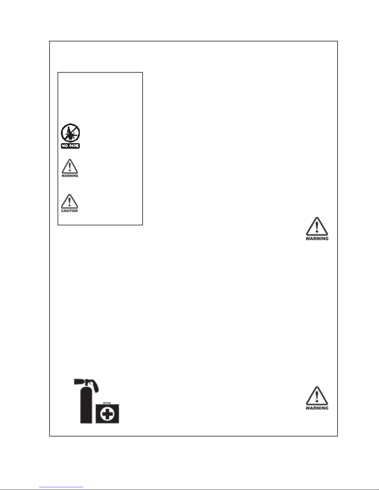
Be Prepared for Emergencies
Keep a first aid kit and fire extinguisher handy.
Keep emergency numbers for doctors, ambulance,
hospital and fire department near your telephone.
N.B. Throughout this
manual important safety
information is indicated
by these symbols in the
margin:
A prohibition should
be observed under all
circumstances.
A warning indicates a
hazard that could cause
death or injury if the
warning is ignored.
A caution indicates a
hazard that may cause
damage to property if
the caution is ignored.
‘Renovator TFD’ Safety
Page 10
8
SAFETY - General (Continued)
Appropriate Dress
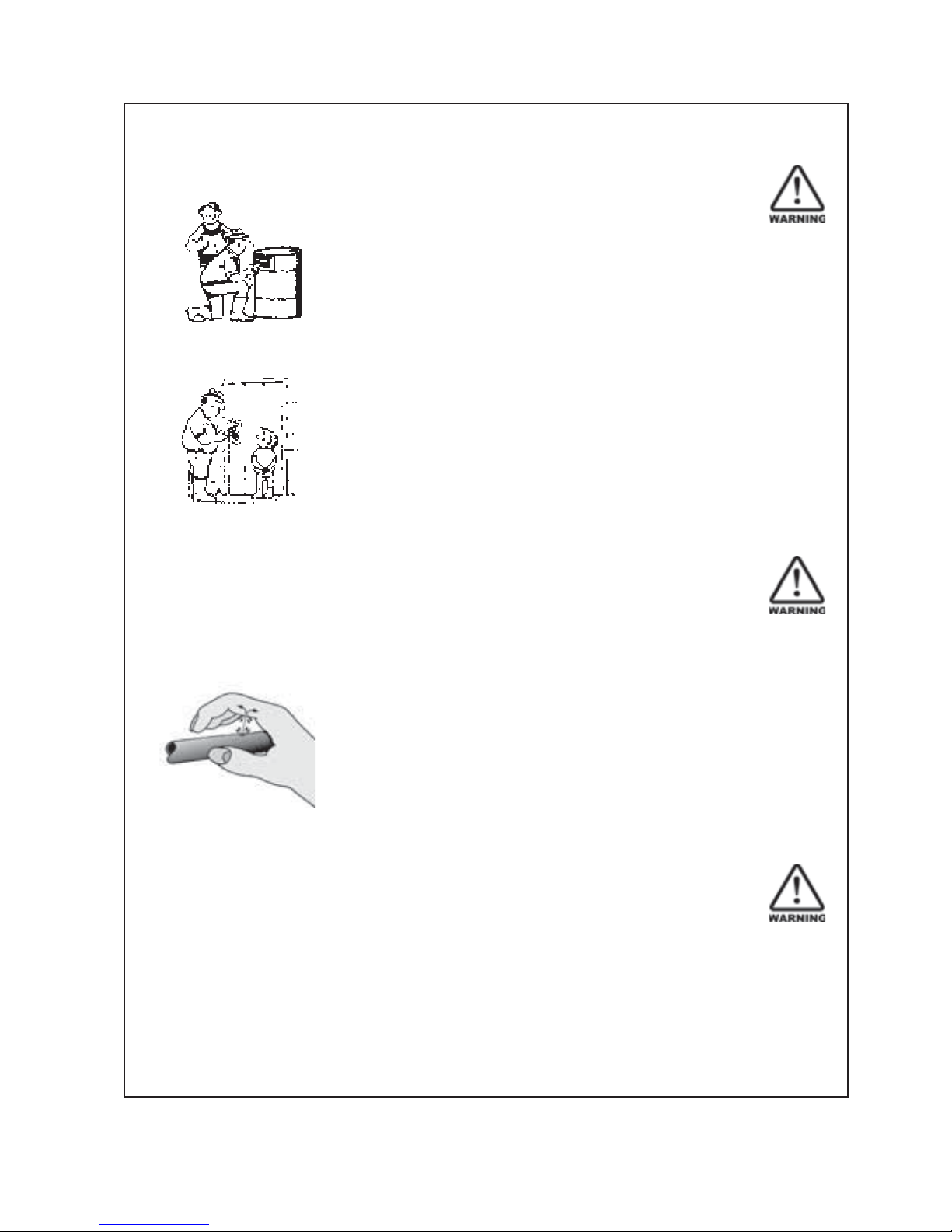
Wear close fitting clothing and avoid rings or other forms of
jewellery which could become caught in the machinery.
People with long hair must have it securely fixed and confined
close to the head.
Refer to local safety standards for protective clothing and
recommended safety equipment.
Adequate protection, such as a face mask, should be worn if
operating this machine in dry and dusty conditions.
Transport This Machine Safely
Ensure that all linkage pins and security clips are fitted correctly.
With trailing machines tow with the drawbar only, as this is the
only safe towing point on the machine.
Always check that bystanders (especially children) are well clear
(front and rear) before starting and moving the tractor and the
machine.
Plan safe routes of travel, and be aware of power lines and
other roadside hazards. Take particular care when towing
implements on hillsides.
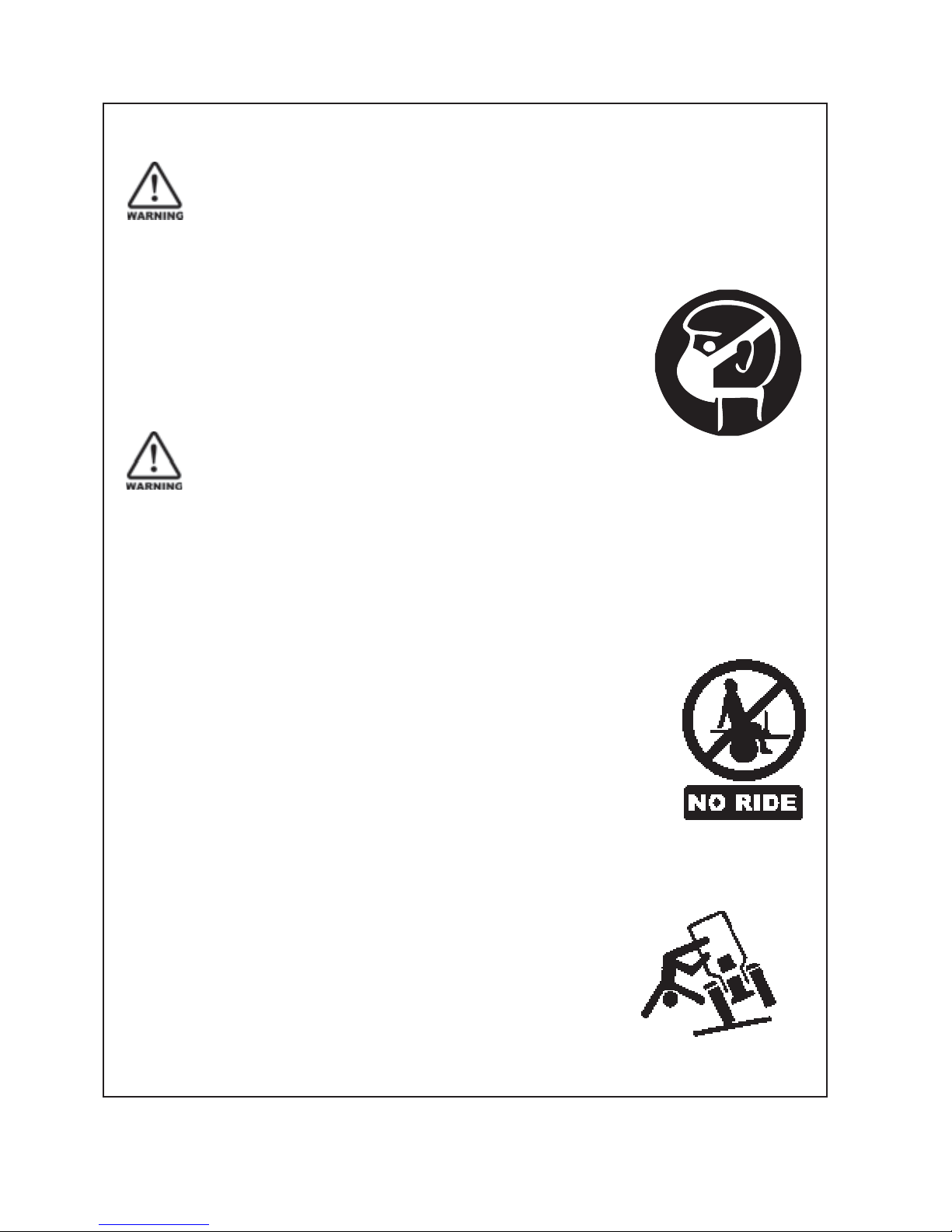
Do not ride or allow passengers on the machine.
This machine is not designed to carry passengers, and no riders
are permitted.
Road transport
On public roads,
• A speed of 40km/h must not be exceeded.
• Do not operate during the hours of darkness unless standard
lights are fitted and clearly visible. (This also applies when
visibility is limited, e.g., in foggy conditions.)
See the guidelines in the Vehicle Dimensions and Mass Rule,
issued by the Land & Transport Safety Authority.
Avoid tip-overs
Avoid holes, ditches and obstructions which may cause the
machine to tip over, especially on hillsides. Never drive near the
edge of a gully or steep embankment - it might cave in. Slow
down for hillsides, rough ground and sharp turns.
‘Renovator TFD’ Safety
Page 11
9
Pt. No. 67415
Issue 0517
SAFETY - General (Continued)
Handle Agricultural Chemicals Safely
All farm chemicals should be stored, used, handled and
disposed of safely and in accordance with the supplier’s/
manufacturer’s recommendations.
Read the product label before using, noting any warnings
or special cautions, including any protective clothing or
equipment that may be required, ie. respirator.
Do not eat or smoke while handling sprays, fertilisers, coated
seeds, etc. Afterwards, always wash your hands and face
before you eat, drink, smoke, or use the toilet.
Store sprays, fertilisers, coated seeds, etc. out of reach of
children and pets, and away from food and animal feeds.
Any symptoms of illness during or after using chemicals
should be treated according to the supplier’s/manufacturer’s
recommendations. If severe, call a physician or get the
patient to hospital immediately. Keep the container and/or
label for reference.
Avoid High Pressure Fluids
Avoid any contact with fluids leaking under pressure, because
the fluids can penetrate the skin surface.
Any fluid which penetrates the skin, will need to be removed
immediately by a medical expert. Seek specialist advice on
this type of injury.
Relieve the pressure before disconnecting any hydraulic or
other lines. Make all repairs and tighten all fittings before
re-connection to pressurised fluid.
Keep your hands and body away from any pinholes or high
pressure jets. Search for leaks with a piece of cardboard
instead of using your hand directly.
Safe Work Practices
All farm machinery is potentially dangerous and should be
treated with caution and respect.
Before starting the machine, ensure that all controls are placed
in neutral and that bystanders are well clear. Check that the
guards have been securely fitted and that any adjustments
have been made correctly.
Where possible, disconnect or isolate the drive mechanism to
the implement. Lower the machine onto the ground when not
in use.
Do not operate this equipment when severe weather
conditions appear imminent.
‘Renovator TFD’ Safety
Page 12

10
SAFETY - General (Continued)
Practise Safe Maintenance
Keep the machine in safe working condition. Routine maintenance
and regular servicing will help reduce risks and prolong the life of the
machine.
General Maintenance
Accidents occur most frequently during servicing and repair. The
following general rules must be followed when maintaining or working
with machinery:
• All operating and maintenance manuals must be
read before and referred to while using or servicing any
piece ofequipment.
• Turn off all machinery power sources and isolate the
machine before making adjustments, doing lubrication,
repairs or any other maintenance on the machine.
• Ensure that the machine hydraulics are disconnected from
the power source.
• Wear gloves when handling components with cutting
edges, such as any ground cutting components.
• Beware of hazards created by springs under tension
or compression when dismantling or maintaining the
machine.
• It is recommended that you clean the machine with a water
blaster or similar apparatus before commencing
maintenance.
Make Sure the Machine is Well Supported
When machinery is fitted with hydraulics, do not rely on the
hydraulics to support the machine. During maintenance or while
making adjustments under the machine, always lock the hydraulics
and support the machine securely. Place blocks or other stable
supports under elevated parts before working on these.
Electrical Maintenance
Disconnect the electrical supply from the tractor before doing any
electrical maintenance.
Welding
With electronic equipment in modern tractors it is advisable to disconnect
the machine from the tractor, or at least disconnect the alternator and
battery before attempting any welding.
Use Only Genuine Spare Parts
Unauthorised modifications or non-genuine spare parts may be
hazardous and impair the safe operation and working life of the machine.
Excess lubricants must be disposed of safely so as not to become a
hazard.
‘Renovator TFD’ Safety
Page 13

11
Pt. No. 67415
Issue 0517
SAFETY - Machine Specific
This section of the manual gives specific guidelines for
the safe operation of the Renovator TFD.
These guidelines were current at the time of publication, but
may be superseded by later circumstances. They do not
necessarily cover every possible hazard and must be read in
conjunction with the SAFETY - General section (Page 6-10).
Hazard Points on the Renovator TFD
The lists below are not all-inclusive and serve only to highlight
the more obvious areas of risk.
The decals attached to the machine are a general reminder
that there are hazardous areas on the machine, rather than
specifically highlighting all possible hazards.
For decal locations on machine, refer Page 13.
No Ride
Passengers are not permitted anywhere on the machine.
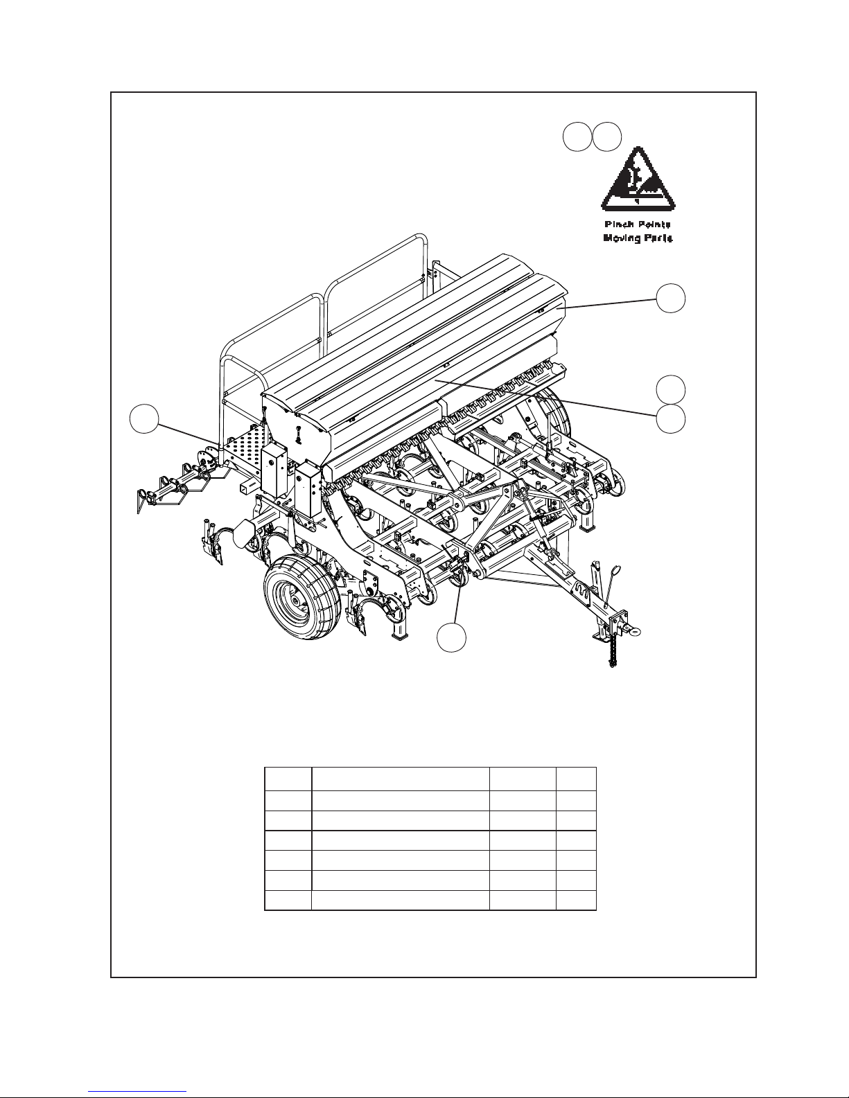
Pinch Points/Moving Parts
Hazardous areas include:
• Drive chains.
• Sprockets between the drive motor, the box shafts and the
agitator shafts.
• Agitator shaft inside the boxes.
• Seeder units, box shaft and shaft connectors.
• Wheel legs and main frame assemblies
• Between tines and the adjuster mechanism.
• Finger tine assemblies (where fitted).
Slippery When Wet
Hazardous areas include:
• Footboards and footstep.
• All smooth surfaces on the frame structure.
Keep Clear
Hazardous areas include:
• Between the tractor and Renovator TFD.
• Immediately adjacent to the Renovator TFD side.
‘Renovator TFD’ Safety
Page 14
12
SAFETY - Machine Specific
(Continued)
Hazard Points on the Renovator TFD
(Continued)
Calibrating
Be particularly careful when calibrating the seeding rate. At
this time, the calibration trays have been removed and are no
longer covering the rotating seeder units. See Pinch Points/
Moving Parts (Page 11) for hazardous areas.
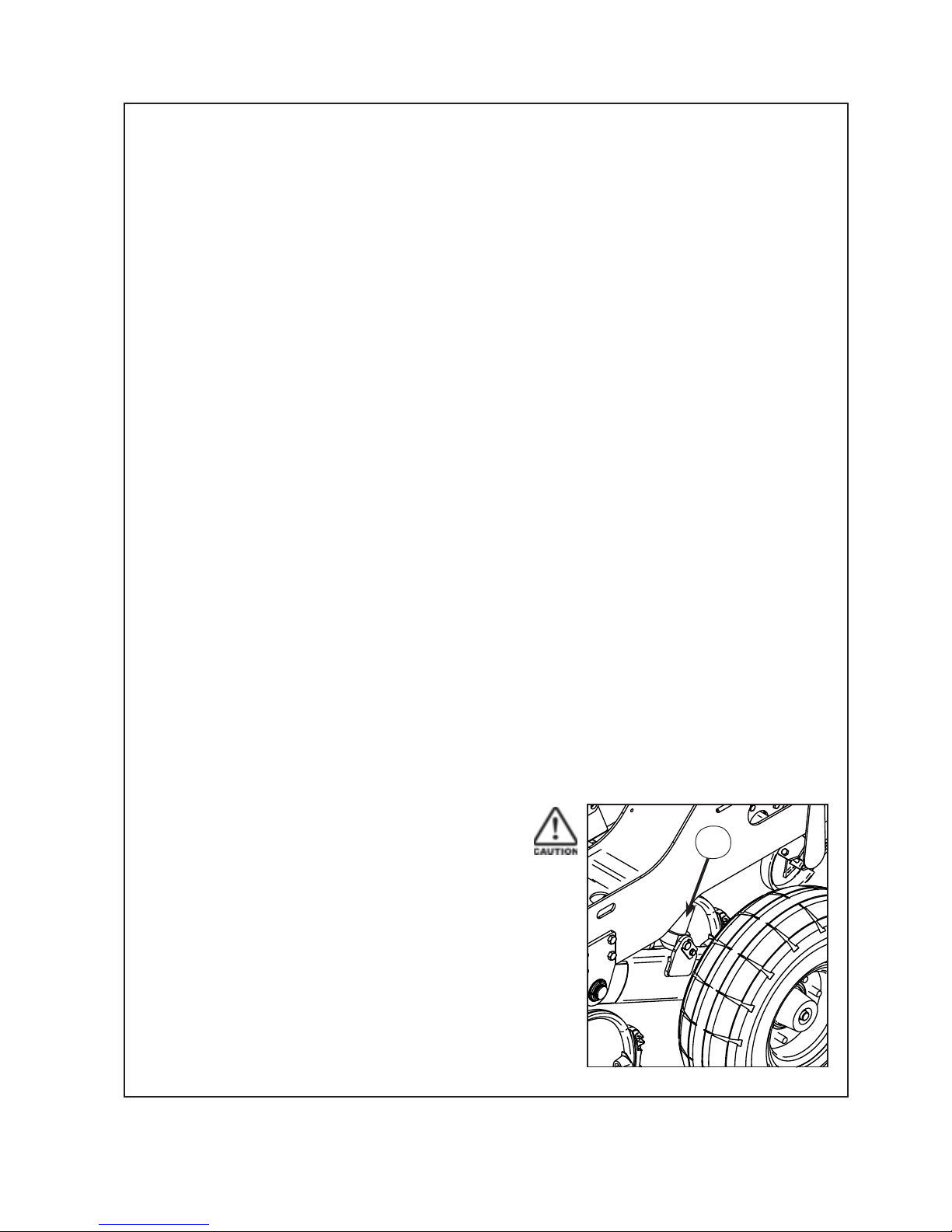
Transport
The two wheels located at the sides of the machine are for the
purpose of controlling sowing depth. These are also used to
support the machine weight during transport (while linked to
the tractor).
Important - Refer to safety cautions in the Transport section,
page 8 of the manual. Ensure that all linkage pins and security
clips are fitted correctly.
Maintenance
Refer Page 28 for reference to the Maintenance and Care
section of the manual.
Lubrication
Refer Page 30 for reference to the Maintenance and Care
section of the manual.
‘Renovator TFD’ Safety
Page 15
13
Pt. No. 67415
Issue 0517
SAFETY - Machine Specific
(Continued)
Inside Box Lid
25
Item Decal/Guard Pt. No. Qty
1 ‘No Ride’ 43900 2
2 ‘Pinch Point/Moving Parts’ 43901 3
3 ‘Slippery When Wet’ 43902 2
4 ‘Keep Clear’ 43909 2
5 Arrows (inside box lid) 43905 2
6 ‘40 km/hr’ 43912 2
4
‘Renovator TFD’ Safety
1
23
6
Both Ends
Page 16

14
Transport
1 Raise the drill into the transport position and hold at the full
extent of the rams for a few seconds to allow cylinders to
equalise.
2
Important - To avoid machine damage due to drill
lowering during transport, always close the hydraulic
valve at the quick release coupling. Move the handle to a
position at 90
0
to the hydraulic line
3
Maximum towing speed 40 km/hr.
For countries other than New Zealand greater speed
restrictions may apply, please refer to your local
transport authority.
Ensure towing vehicle requirements are adequate
for the towed vehicle e.g. mass, brakes. Refer to
recommendations published by the local Land Transport
Authority or equivalent.
Braking when towing can cause the load to jackknife. Use
extra care when towing in adverse conditions such as mud,
inclines and sharp bends.
Lower towing speeds are recommmended on farm roads/
tracks and where one wheel is on or over a road verge.
‘Renovator TFD’ Operation
Page 17
15
Pt. No. 67415
Issue 0517
Operation
General Operation Guidelines
1 Use a sufficiently powerful tractor which is heavy enough to tow the drill safely.
2 Operate the drill at a speed of 6-12 km/hr (4-8 mph).
In stony and uneven ground conditions a lower speed is more appropriate
3 Check that the drill is level during calibration and while seeding.
4 Check tyre pressure before seeding. Refer page 5.
5 Double check seed rates before seeding.
6 Raise the drill out of the ground when making any turns.
7 Raise the drill out of the ground before backing up.
8 Stretched sagging hoses disrupt seed flow. Slight tension may be restored by carefully shortening
the affected hose; remove from the tube at ground level and cut accordingly.
Care must be taken not to shorten too much as the tension will pull the hose from the ground tube
or damage the plastic metering funnel.
9 After prolonged storage, check to see that all drive mechanisms and hydraulic equipment are functioning
correctly. Check that the seed/fertilizer tubes are not perished or blocked.
Sowing Speed
Typical travel speeds when sowing range from 6-12 km/hr in good conditions. In stony and uneven
ground conditions a lower speed is recommended to minimise rapid part deterioration. Sowing too fast
can result in:
1 Poor contour following and uneven sowing depth.
2 Impact damage to:
a Ground engaging components.
b Bearings, housings & axles.
c Fasteners & structural components.
3 More extreme conditions will result in greater vibration
and uneven seed flow at low seeding rates.
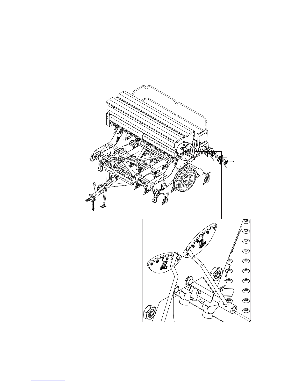
Sowing Depth Control
The sowing depth is dependent on:
1 The wheel height in relation to the chassis
2 Tyre pressure
3 Ground condition i.e. hard or soft
The wheel height in relation to the chassis is controlled using the
threaded depth adjustment collar (1) on the left hand wheel leg
ram. The rams are phasing and the left hand ram controls the
overall depth. The threaded collar on the right hand ram can be
adjusted to take up the clearance on this side. In this way, in the
event of hydraulic failure the preset depth is maintained.
Caution: Do not over-extend the thread depth adjustment. Clip on
depth stop collars may be added to both sides if more control is
required.
‘Renovator TFD’ Operation
1
Page 18

16
Magnetic Cut-out Sensor
To enable seeding to start and when the machine is
lowered into and lifted out of the ground, a magnetic
sensor is fitted on the RH wheel leg hydraulic ram. The
sensor position may be adjusted to suit the ground and
sowing conditions.
Level Drill
Use the drawbar turnbuckle to tilt the drill so it is sitting
level. Ensure that the front and rear rows are at an even
depth.
Transport Position
When in the transport position the hydraulic cylinders are
fully extended.
‘Renovator TFD’ Operation
Page 19

17
Pt. No. 67415
Issue 0517
‘Renovator TFD’
Page 20
18
‘Renovator TFD’ Read Before Calibration
Components Referred to in the Pre-Calibration Setup and Calibration Process
The following pages describe how to set the machine up for calibration, the calibration process and
subsequent adjustments to obtain the desired seed and/or fertilizer output.
Terms and words used in those instructions are shown below:-
‘Left’ and ‘Right’ on the machine are with respect to the direction of forward travel.
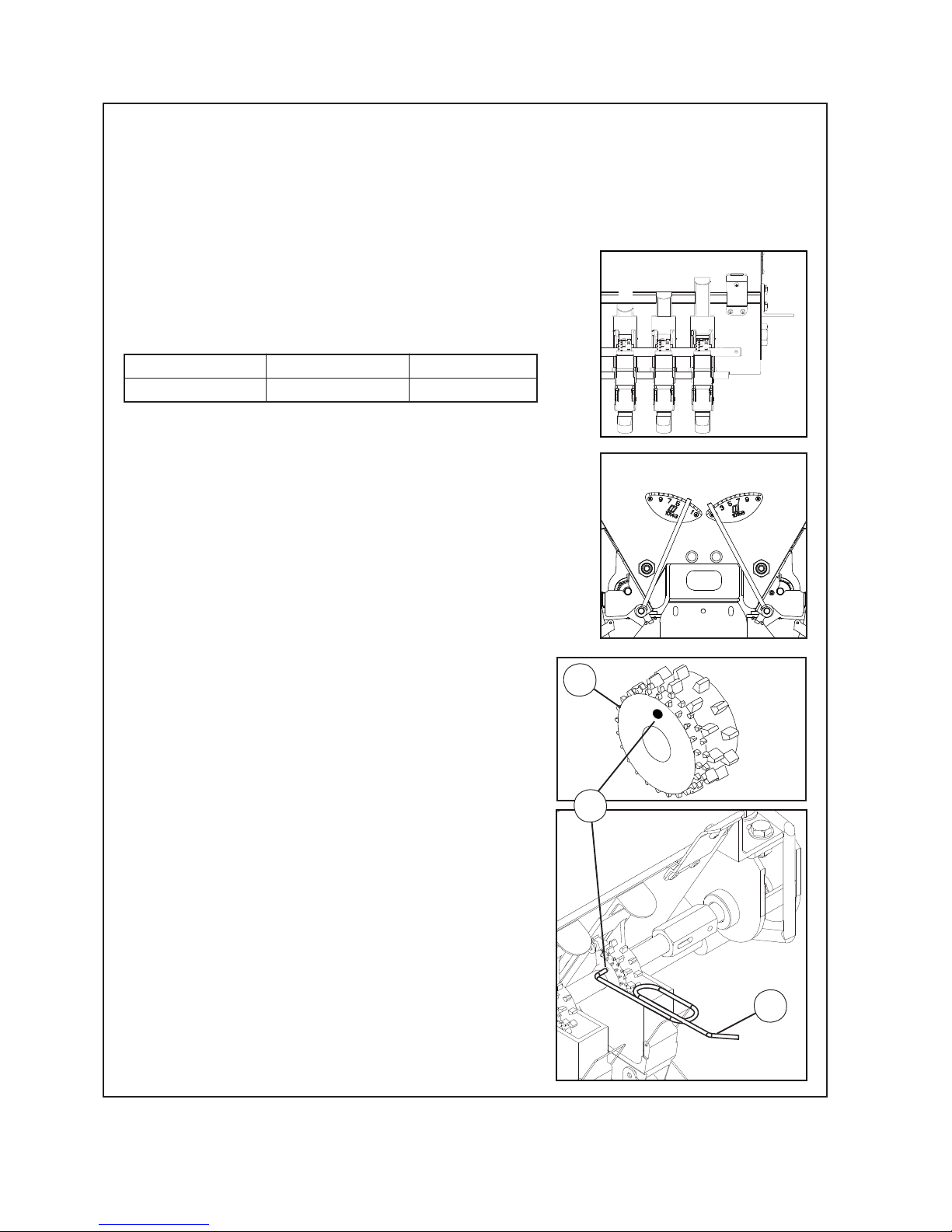
Shutter Slides
The varying flow properties of seeds require different shutter
slide positions which may be found in the Sowing Chart for the
individual type of seed or fertilizer. This corresponds to one of
the three settings as shown.
Bottom Flap Settings
The various seed sizes require matching bottom flap clearances
below the metering wheel. The adjusting plate allows for 10
different settings. The required position for the seed type may
be found in the Sowing Chart. The control levers are located
on the LH end of the seedbox, (opposite end to the electric
motors).
Number “1” corresponds to the minimum (closed) position and
“10” the maximum gap.
A B C
Closed 3/4 Open Fully Open
A
B
C
10
1
10
1
3
2
Metering Wheel - Sowing Fine Seeds
For sowing fine seeds the Renovator TFD is equipped as
standard with a combined normal and fine seed
“Elite” metering
wheel, 1.
During grain sowing and other larger varieties of seed both the
normal and fine seed metering wheels are coupled and both rotate.
In order to convert the seed drill to sow fine seed, rotate the box
shaft clockwise until the holes
of the fine seed wheel, 2, are
visible. This is achieved by pressing and releasing the priming
switch thus instructing the electric motors to rotate the seed
shaft. By trial and error the holes can be located.
Using the tool supplied, 3, disengage the the pin inside the
hole so that the normal metering wheel rotates freely on the
metering shaft.
At this time it would be advisable to close any shutter slides
not required for the fine seed sowing.
When seed is to be sown again using the normal metering wheel
press the pin, from the normal metering wheel side (opposite
direction to before), using the tool, back into the hole of the fine
seed wheel thus reconnecting the drive between the two.
Page 21
19
Pt. No. 67415
Issue 0517
‘Renovator TFD’ Read Before Calibration
Components Referred to in the Pre-Calibration Setup and Calibration Process
The following pages describe how to set the machine up for calibration, the calibration process and
subsequent adjustments to obtain the desired seed and/or fertilizer output.
Terms and words used in those instructions are shown below:-
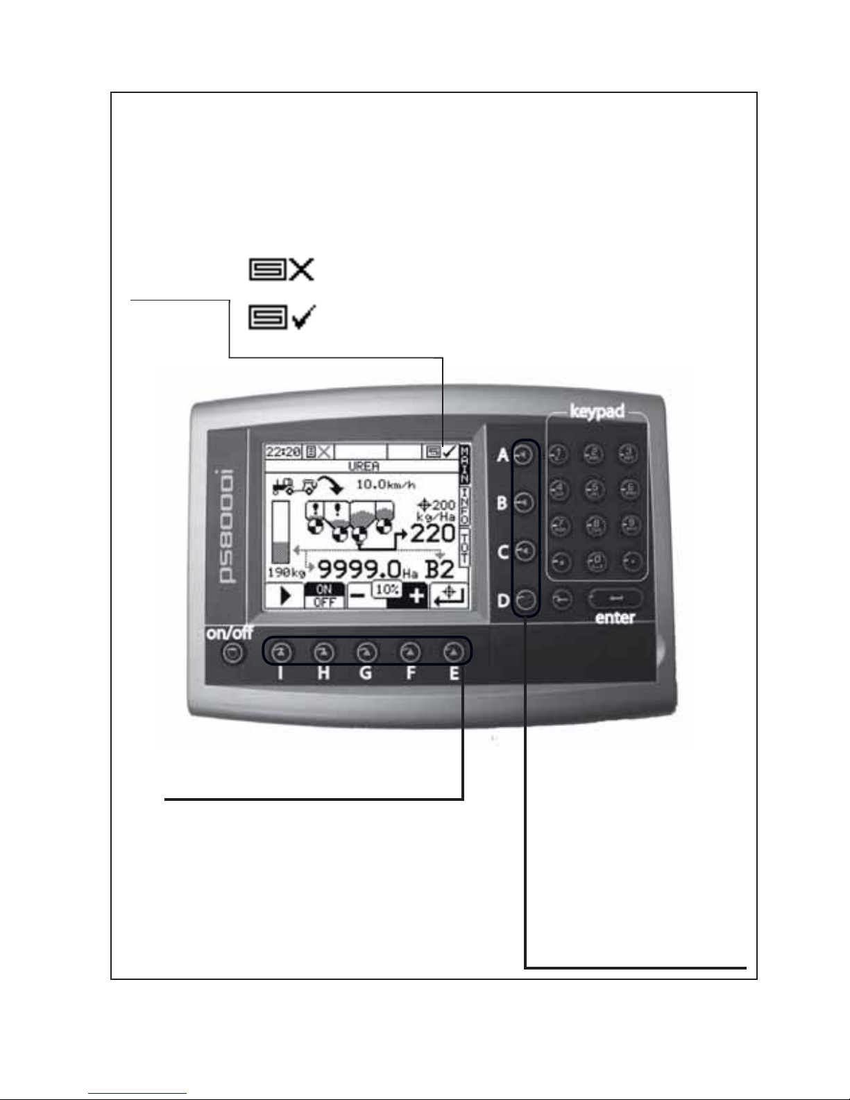
General Controls and Main Operating Screen
OUT OF WORK- the machine is raised up for turning or transport
‘AREA CUTOUT’
IN WORK- the machine is lowered ready for drilling
‘MENU KEYS’
A ‘MAIN’ The default screen as
shown above.
B ‘INFO’ Access and edit
information regarding bin
contents.
C ‘TOT’ Displays the amount of
product dispensed and the area
covered.
D ‘MENU’ Machine setup and
diagnostics access screen.
‘SUB-MENU SOFT KEYS’ -the function
changes for each screen. The icon above each
button is the function.
Page 22
20
‘Renovator TFD’ Read Before Calibration
Components Referred to in the Pre-Calibration Setup and Calibration Process
The following pages describe how to set the machine up for calibration, the calibration process and
subsequent adjustments to obtain the desired seed and/or fertilizer output.
Terms and words used in those instructions are shown below:-
Priming Switch Buttons
Priming Switch Operation
The priming switches are located on the left
hand end of the dualbox. There is one switch per
box.
Priming switches are used to start the calibration
process. Pressing the button for about 1 second
then releasing will start the appropriate seeder
shaft. Pressing the button again for about 1
second will stop the rotation.
Whilst this is mainly used for calibration it is also
useful for priming the seeder units and testing
motor operation. The Main Operating Screen will
change to calibration mode when the Priming
Switches are pressed. The operator can exit
this mode without affecting any settings. More
information and operating screen pictures are
shown in the calibration section.
Page 23
21
Pt. No. 67415
Issue 0517
‘Renovator TFD’ Read Before Calibration
Power On Routine
Note: The machine must be up in the Transport Position for the ‘Power On Routine’ to work.
When the instrument is first turned on the instrument will enter a short routine to remind the operator
of the previous setup. The set up can be changed and then accepted by pressing the ENTER key or
alternatively, the routine can be skipped by pressing the MAIN button (Key A).
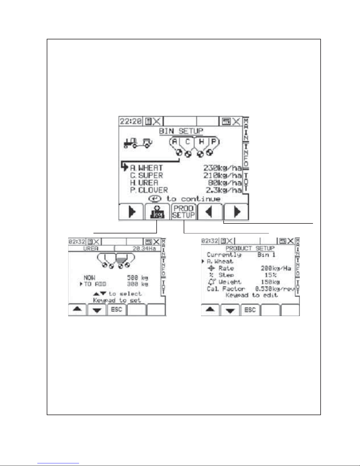
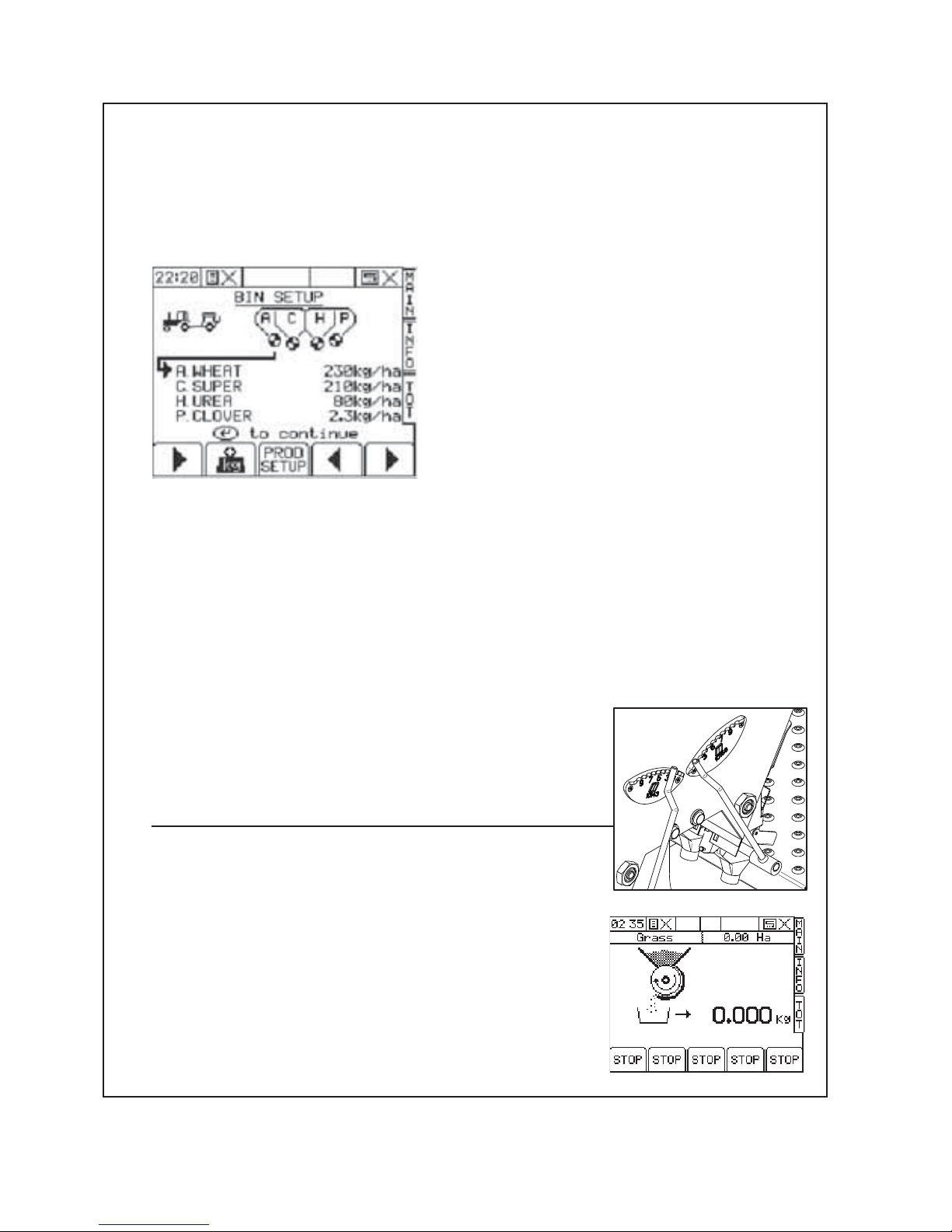
The first screen on start up is the BIN SETUP screen. This screen advises the operator which products are
defined to which bin. On the screen format shown below the operator can use the ‘PRODUCT LIST’ keys
to cycle through the list of products. The application rate saved against that product will also be shown.
The letter shown in the graphic will also change to reflect the product selected.
‘PRODUCT LIST’
‘PROD SETUP’‘BIN CONTENTS’
Startup Screen Display Features
The ‘BIN CONTENTS’ button enables the operator to program the contents of the bin. The ‘NOW’ value
refers to the calculated current contents of the bin based on the work done. This value can be changed
directly by selecting ‘NOW’ and using the key pad and pressing enter. Alternatively, when a specific
amount of product is being added to the bin, select ‘TO ADD’ and use the key pad and press enter to add
to the ‘NOW’ total. Pressing the ‘ESC’ (escape) key returns to the previous ‘INFO’ screen.
The ‘PROD SETUP’ screen allows the operator to change the details of the products in the directory.
There is a directory of 16 products and against each of these 4 factors are recorded. These factors are
target rate, step size, alarm weight and calibration factor. Note: the calibration factor is calculated by the
machine during the calibration process. The only reason to alter this setting manually is when the user
enters wrong information during the calibration process which can stop the motors from working. A list of
default Cal Factors are shown in the calibration section.
Page 24
22
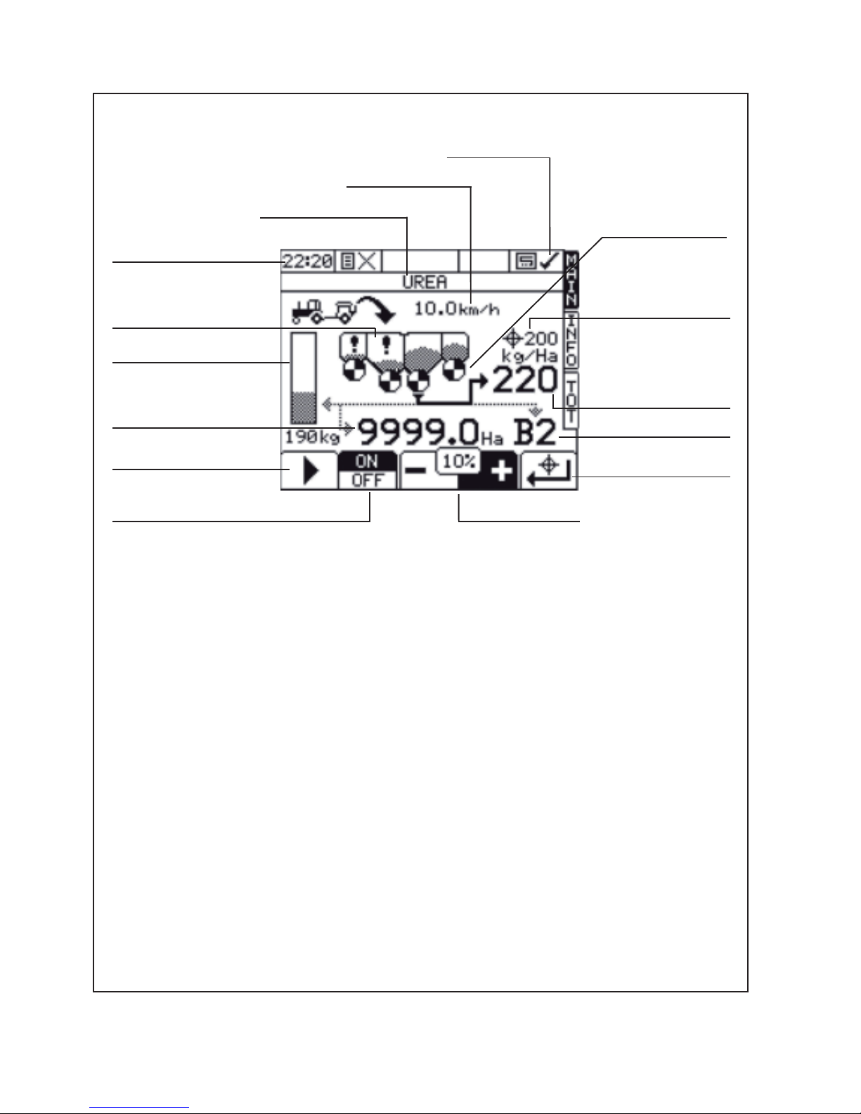
Main Operating Screen
‘Renovator TFD’ Read Before Calibration
Main Screen Display Features
The screenshot above shows the status of Bin 2 (Rear Bin). The ‘BIN SELECTION’ button cycles through
the bins. The line under the metering roll will move to the next bin and the details for that bin will be shown.
When the machine is in use, the metering roll animates to show the bin motor is rotating. The ‘CURRENT
RATE’ is shown. ‘TARGET RETURN’ resets the ‘CURRENT RATE’ to the ‘TARGET RATE’ and cancels
and ‘STEP CHANGE’ applied.
If the ‘BIN MOTOR ON/OFF’ is pressed the bin motor will toggle between these on and off. The metering
roll animation will be replaced with a cross to indicate the bin has been switched off.
Note: The TFD has bins 1 (front) & 2 (rear) as standard. A Small Seed box is optional and is designated
bin 3 when fitted.
Whilst the MAIN screen is displayed, an alternative MAIN SUMMARY screen may be displayed by
pressing the MAIN button. You may cycle betwen the two MAIN screens by pressing the MAIN button.
Clock
‘AREA CUTOUT’
‘FORWARD SPEED’
‘PRODUCT SELECTED’
‘LOW LEVEL
REMINDER’
‘BIN CONTENTS LEVEL’
‘TARGET RATE’
‘CURRENT RATE’
‘STEP CHANGE’
the current rate
can be increased
or decreased by
the % shown from
the target rate.
‘BIN NUMBER’
‘BIN SELECTION’
‘BIN MOTOR ON/OFF’
‘P ART AREA’ SOWN FOR
SELECTED PRODUCT
‘METERING ROLL’
‘TARGET RETURN’
Page 25
23
Pt. No. 67415
Issue 0517
‘Renovator TFD’ Read Before Calibration
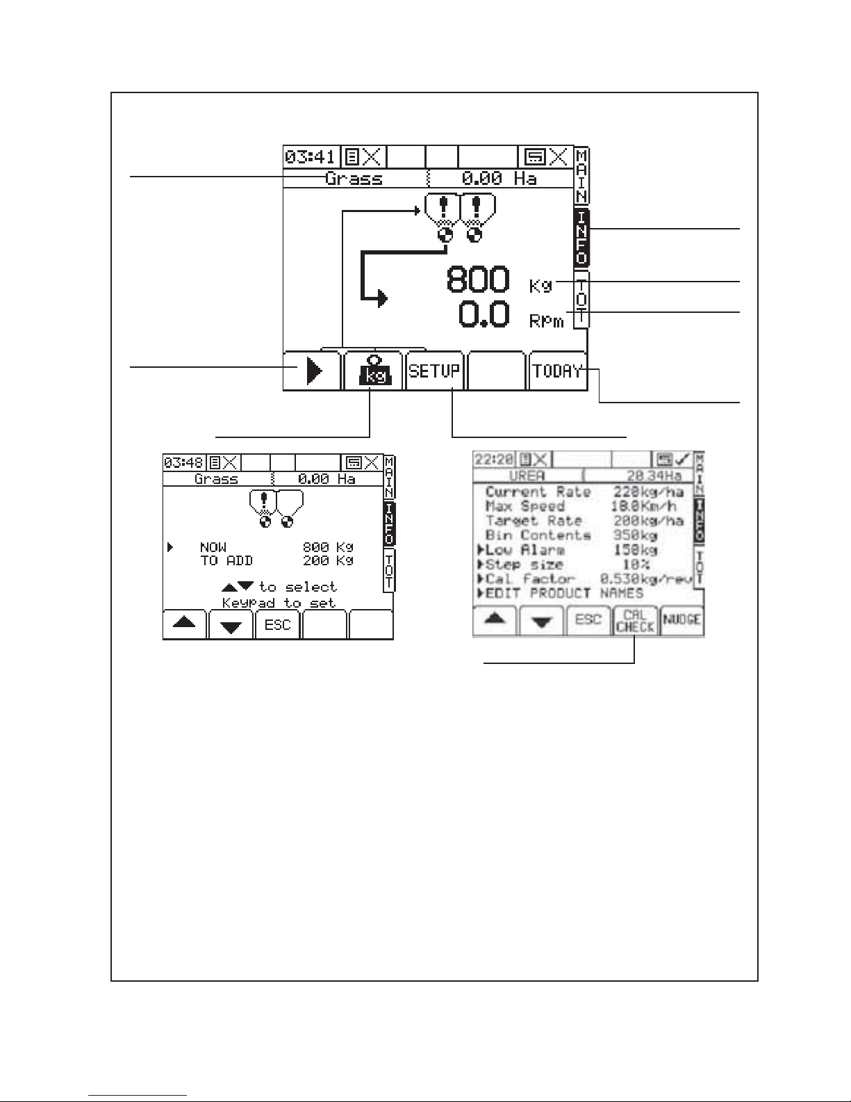
Info Screen -Individual Info Screen shown below.
Info Screen Display Features
The ‘BIN SELECTION’ button cycles through the bins. The line under the metering roll will move to the
next bin and the details for that bin will be shown. The ‘PRODUCT’ shows the product for the bin selected.
The ‘BIN CONTENTS’ button enables the operator to program the contents of the bin. The ‘NOW’ value
refers to the calculated current contents of the bin based on the work done. This value can be changed
directly by selecting ‘NOW’ and using the key pad and pressing enter. Alternatively, when a specific
amount of product is being added to the bin, select ‘TO ADD’ and use the key pad and press enter to add
to the ‘NOW’ total. Pressing the ‘ESC’ (escape) key returns to the previous ‘INFO’ screen.
The ‘INFO SETUP’ screen allows changes to the items marked with a cursor arrow. Changes to these
settings will change the settings for the product.
The ‘CALIBRATION CHECK’ is one way to start the calibration procedure. Refer to the following section.
‘BIN SELECTION’
‘PRODUCT
REMAINING’
‘SHAFT SPEED’
‘INFO’- cycle between
individual and
summary info
screens.
‘PRODUCT’
‘BIN CONTENTS’ ‘INFO SETUP’
‘TODAY’-shows
the qty of product
metered and duration
for today only.
‘CALIBRATION CHECK’
Page 26
24
‘Renovator TFD’ Calibration
Calibration Procedures
The calibration test should be done to confirm the settings of the required seed rate and is done with the
drill stationary and level. Please ensure that you have read the previous section.
1 Power On the console.
2 You will be presented with the BIN SETUP screen. Make any changes to product or target sowing
rates now.
3 Prepare a suitable area for weighing and setup the scales. Tare the scales with the same container
that will be used to weight the product. Scales must be accurate to 2 grams
4 Refer to the sowing chart (page 28) for the chosen product. Set the Shutter Slides, Bottom Flaps and
Metering Wheels in accordance with the sowing chart.
5 Remove the calibration trays from the bracket on the seedbox. Place the trays on the calibration tray
brackets on the seedbox.
6 Push down all the clear plastic seed directors to redirect seed into the calibration trays.
7 For the calibration check, half fill the appropriate box with product. If this is not possible, make sure
the product is evenly distributed over all the seeder units in the box.
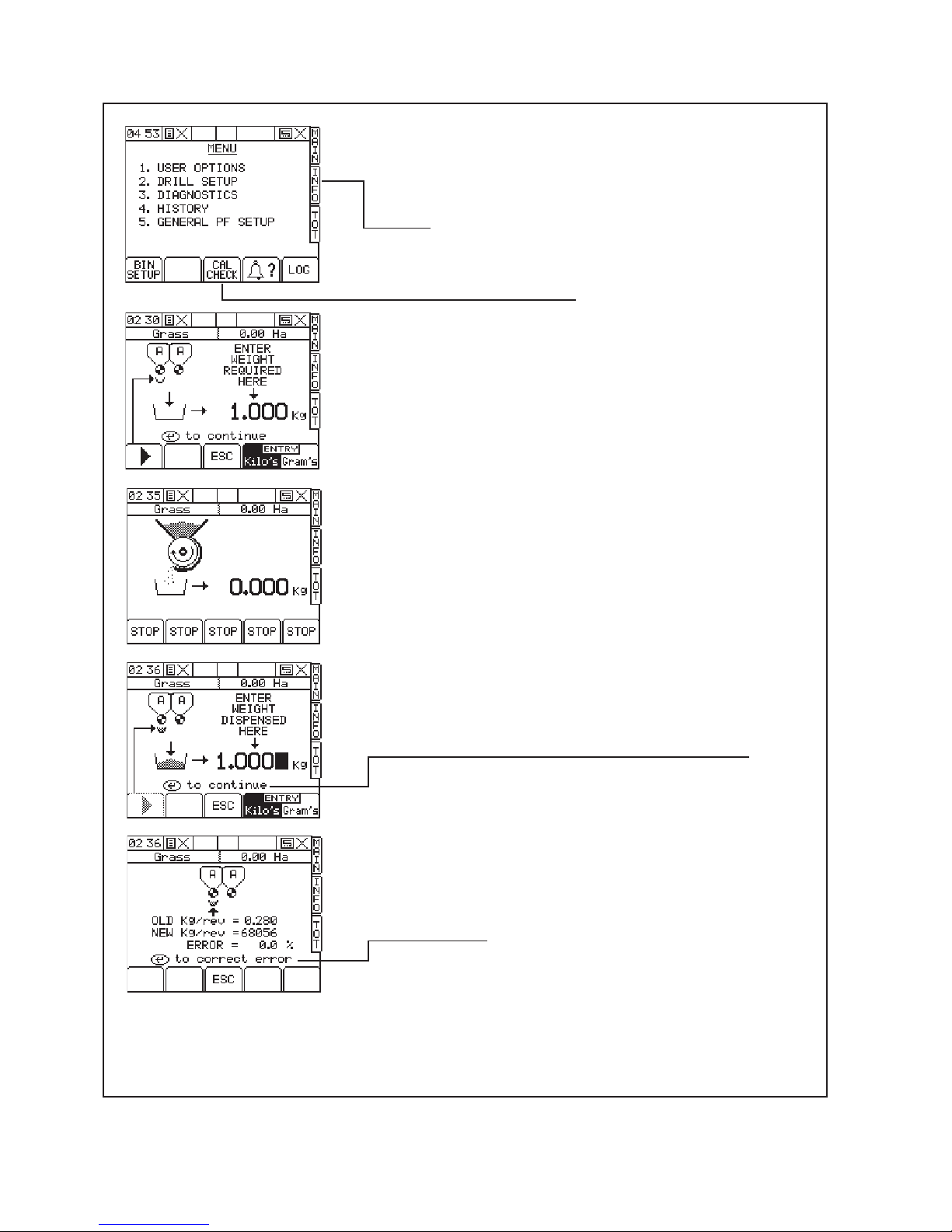
8 The calibration process can be in initiated in two ways:
(i) By pressing the appropriate ‘PRIMING SWITCH’
(ii) Via the SETUP menu.
Each of these methods are described in the next few pages.
The PRIMING SWITCH method is easier and more convenient.
(i) Calibration via PRIMING SWITCH (recommended)
1 Press and hold the appropriate ‘PRIMING SWITCH’ for 1
second then release.
2 The Operating Screen will change as shown. It is likely the
operator will be standing near the priming switches at this
time so will not see the display. It is only after weighing the
dispensed product that the operator need visit the tractor cab.
If the operator presses ‘STOP’ the calibration will be cancelled;
no seting will be altered. This may occur if the priming switch is
pressed to just prime the seeder units or test the motor drive.
Page 27
25
Pt. No. 67415
Issue 0517
‘Renovator TFD’ Calibration
Calibration via PRIMING SWITCH (continued)
3 The appropriate metering unit will run until the PRIMING
SWITCH is pressed again. Product is collected in this
time. The operator is in control of the amount of product
metered out so is able to stop the metering unit when
the calibration trays are at a suitable fill level.
4 Weigh the contents of the calibration trays. Write down
the amount exactly as displayed. Do not round up or
round down the value measured. Scales must be
accurate to 2 grams.
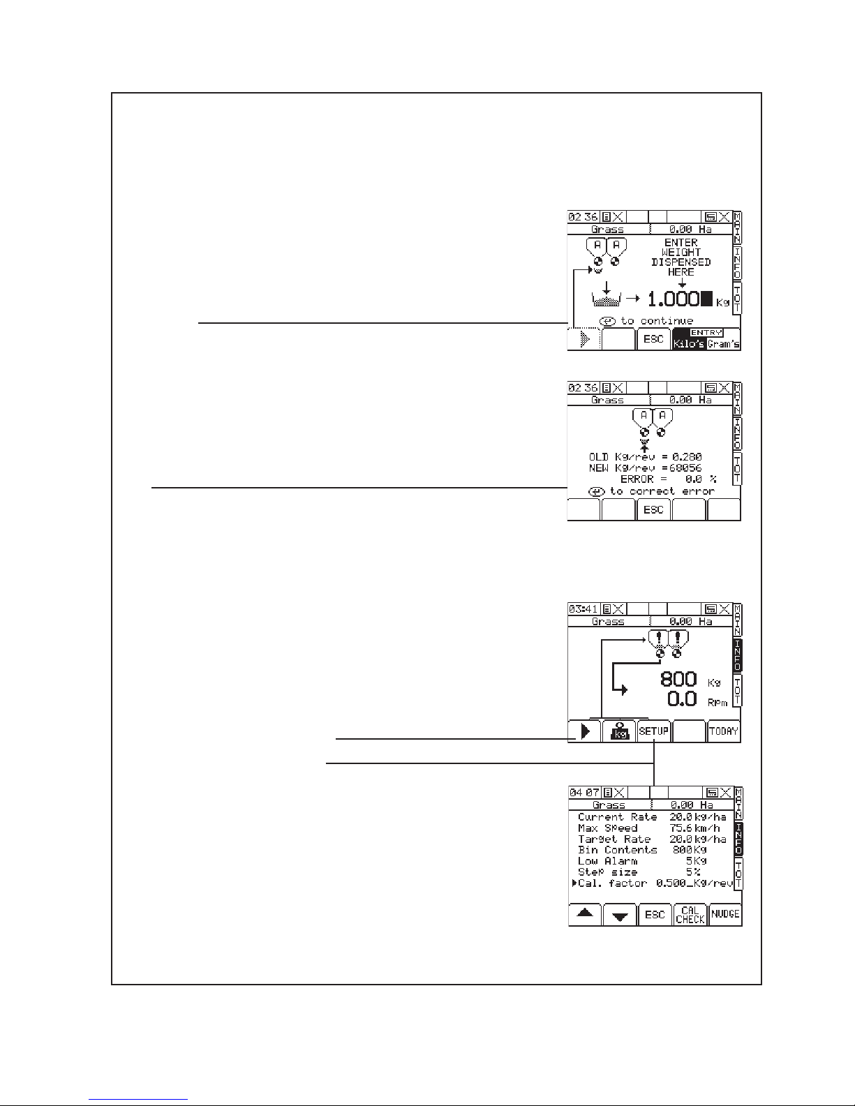
5 Enter the recorded value into the Operating Screen as
shown. Press ‘ENTER’ to confirm as requested.
Always use consistant units of measure ie grams or
Kilograms.
6 Press ‘ENTER’ again. The instrument will then calculate
the settings in order to correctly deliver the product. The
‘error’ value is only the difference between the new and
old settings. Subsequent recalibrations with the same
product will only report small differences.
7 Press ‘ENTER’ again to confirm and store the new
settings.
8 Repeat the calibration process. In this case, the ‘Error’
reported will be very small if any. Remember to press
the ‘ENTER’ key to accept the settings. This repeat
calibration is especially important if the metering units
have been adjusted from very different values since the
last time the machine was used.
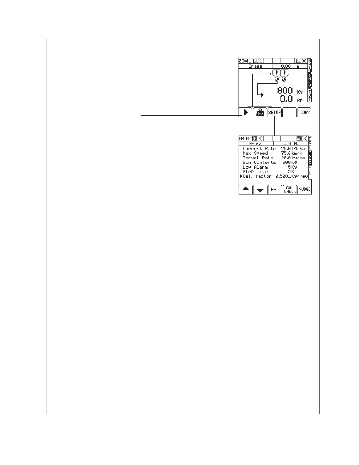
9 NOTE: If, when presing the priming switch the motors
do not turn but there are no other errors, it could be
that the previous calibration was wrongly entered. The
metering speed is out of the range of the motor speed.
This can be corrected by manually entering a ‘calibration
factor’ as follows:
(i) Press the ‘INFO’ menu key.
(ii) Select the appropriate bin.
(iii) Press the ‘SETUP’ key.
(iv) Use the up down arrows to select the ‘Cal. factor’
line.
(v) Type 0.500 and hit the ‘ENTER’ key. (You need to
enter the leading zero as the machine will not accept
the ‘.’ as a first character.) Note that although the default
calibration factor for Grass is 0.28 kg/rev resetting to
0.500kg per rev gets the machine working again for
re-calibration.
(vi) Hit the ‘ESC’ key to return to the ‘SETUP’ menu or
hit the ‘MAIN’ key to return to the ‘MAIN’ menu.
(vii) Repeat the calibration process from step 1.
Page 28
26
(ii) Calibration via ‘SETUP’ MENU
1 Ensure that steps 1 to 8 on page 22 have been carried
out prior to actual calibration.
2 Navigate to the ‘MENU’ screen by pressing the ‘MENU’
key.
3 Access the ‘Calibration Check’ screen by hitting the
‘CAL CHECK’ button.
4 The screen will then prompt, “Enter weight required
here”. Select the bin that you want to calibrate by
pressing the arrow key.
Enter the amount required. Hit ‘ENTER’ to continue
Remember to set and keep to consistant units.
Note that this is is only related to calibration and
weighing; it is not related to the sowing rate entered
on the startup screen earlier.
6 The machine will dispense the amount you entered
based on the current settings. If the product or seeding
rates are different from the last time the machine was
used then the amount metered may not be as expected.
If you suspect that the calibration container will overflow
then you can stop metering process by hitting one of the
5 keys along the bottom of the screen.
7 Once the machine has stopped the calibration delivery,
either because it has reached the amount you entered
or you forced it to stop, weigh the contents of the
container. Write down the amount exactly as displayed.
Do not round up or round down the value measured.
Scales must be accurate to 2 grams.
8 Enter the recorded value into the Operating Screen as
shown. Press ‘ENTER’ to confirm as requested.
Always use consistant units of measure ie grams or
Kilograms.
6 Press ‘ENTER’ again. The instrument will then calculate
the settings in order to correctly deliver the product. The
‘error’ value is only the difference between the new and
old settings. Subsequent recalibrations with the same
product will only report small differences.
7 Press ‘ENTER’ again to confirm and store the new
settings.
8 Repeat the calibration process. In this case, the ‘Error’
reported will be very small if any. Remember to press
the ‘ENTER’ key to accept the settings. This repeat
calibration is especially important if the metering units
have been adjusted from very different values since the
last time the machine was used.
‘Renovator TFD’ Calibration
Page 29
27
Pt. No. 67415
Issue 0517
‘Renovator TFD’ Calibration
(ii) Calibration via ‘SETUP’ MENU continued
9 NOTE: If, when presing the priming switch the motors do
not turn but there are no other errors, it could be that the
previous calibration was wrongly entered. The metering
speed is out of the range of the motor speed.
This can be corrected by manually entering a ‘calibration
factor’ as follows:
(i) Press the ‘INFO’ menu key.
(ii) Select the appropriate bin.
(iii) Press the ‘SETUP’ key.
(iv) Use the up down arrows to select the ‘Cal. factor’
line.
(v) Type 0.500 and hit the ‘ENTER’ key. (You need to
enter the leading zero as the machine will not accept
the ‘.’ as a first character.) Note that although the default
calibration factor for Grass is 0.28 kg/rev resetting to
0.500kg per rev gets the machine working again for
re-calibration.
(vi) Hit the ‘ESC’ key to return to the ‘SETUP’ menu or
hit the ‘MAIN’ key to return to the ‘MAIN’ menu.
(vii) Repeat the calibration process from step 1.
Page 30

28
‘Renovator TFD’ Calibration Sowing Chart
Settings for Seed Type
Seed Type
Default Calibration
Factor (kg/rev)
Shutter Slide1Bottom Flap2Metering Wheel
3
Wheat 0.70 3/4 3 N
Oats 0.69 Full 3 N
Barley 0.69 Full 3 N
Ryecorn
- Full 3 N
Peas 1.00 3/4 3 N
Grass 0.28 Full 3 N
Grass Mix 0.30 Full 3 N
DAP Granules 0.94 Full 3 N
Super Phosphate 1.20 Full 3 N
Lucerne/Alfalfa 0.10 3/4 1 F
Turnip 0.093 3/4 1 F
Kale 0.092 3/4 1 F
Swede 0.093 3/4 1 F
Canola/Rape 0.09 3/4 1 F
White Clover 0.094 3/4 1 F
Red Clover 0.094 3/4 1 F
NOTES
1. SHUTTER SLIDE
For grain, opening the shutter slide to Full gives 10-15% more flow.
2. BOTTOM FLAP
The values shown were the optimum test settings.
Decreasing the gap may cause seed damage.
Too large a gap will give intermittent flow rates.
Flaps are spring loaded to cope with small variations in seed/granule size.
3. METERING WHEEL
N = Normal metering wheel
F = Fine metering wheel only
TSW: TSW(gm) x Desired Plants/m
2
= Sowing Rate (Kg/Ha)
Germination %
Page 31

29
Pt. No. 67415
Issue 0517
‘Renovator TFD’ Calibration Notes
Page 32

30
General Safety and Accident Prevention Advice
1 Make sure that if the tractor remains attached to the drill
that the ignition key is removed.
2 During maintenance the drill should be supported in such
a manner that if hydraulic failure was to occur the machine
would still be adequately supported.
3 Wear gloves when handling components with cutting
edges such as worn discs etc...
4 Disconnect the electrical supply from the tractor before
doing any electrical maintenance.
5 Refer to safety sections for more safety information.
General Cautionary Maintenance Advice
1 Electric Welding - With the electronic equipment in
modern tractors it is advisable to completely disconnect the
implement from the tractor, or at the very least disconnect
the alternator before attempting any welding.
2 Hydraulics - Ensure hydraulic couplings (male & female)
are clean before connecting. Dirty couplings will result
in hydraulic oil contamination and hydraulic cylinder seal
damage and bore scores. This in turn will result in oil
leakage past the piston seals.
No filter is fitted to the hydraulic system. If hydraulic
fittings and oil supply are not going to be kept clean it is
recommended that a filter be fitted to prevent hydraulic
cylinder damage.
3 Water Blasting - Water blasting, steam cleaning or other
pressurised cleaning processes can force dirt etc. into
undesirable places that may cause damage or rapid part
wear to items such as bearings, seals, chains, bushes etc.
Caution must be exercised.
‘Renovator TFD’ Maintenance & Care
Page 33

31
Pt. No. 67415
Issue 0517
Lubrication Chart
Maintenance & Care - Lubrication Instructions
* The lubrication frequencies are only a guide. Actual frequency will be dependent on extent of use and ground conditions.
Precautions with Grease
Greases should not be mixed as the structure may be weakened by the
mixes of different types of thickener, which may cause softening and loss of
grease from the bearings by running out.
Item Components Lubricant Frequency*
1 Wheel Bearings Castrol LMX Grease Annually
2 Wheel Leg Pivots Castrol LMX Grease Weekly
3 Drive Chains Suitable Roller Chain Lubricant See Maintenance Schedule
4 Turnbuckles Castrol LMX Grease Monthly
5 Coupling Castrol LMX Grease Monthly
Your new Duncan Renovator TFD will
give long and efficient service if given
normal care and maintained properly.
1
2
4
5
3
‘Renovator TFD’ Maintenance & Care
Page 34

32
Maintenance Schedule
(
Refer also to Summary Chart, above)
1. Bolted Connections
All bolted connections of the machine should be checked after the first 3 to 5 hours of operation and
retightened if necessary and thereafter at regular intervals. It is suggested that this is done every 500
hectares or annually, whichever occurs first.
2. Hydraulics
Ensure hydraulic couplings (male & female) are clean before connecting. Dirty couplings will result in
hydraulic oil contamination and hydraulic seal and bore damage which will cause oil leakage past the
seals.
No filter is fitted to the hydraulic system. If the hydraulic fittings and the oil supply are not going to
be kept clean then it is recommended that a filter be fitted to prevent hydraulic cylinder damage.
3. Drive Chains
All drive chains (1) should be checked after every 20 hours of operation and weekly thereafter or
after 75Ha of operation.
The metering wheels of the seed drill are driven via roller chains from the gearmotor.
4. Wheel Arm Pivots
Wheel arm pivots must be greased regularly (weekly or after every 75Ha) to provide lubrication and
flush out any dirt.
6. Tyre Pressure
The recommended tyre pressures may be found on page 5. Check the tyre pressure regularly to
ensure correct pressure is maintained. Weekly checks are recommended.
7. Length of Seed/Fertiliser Tubes
These tubes can stretch over a period of time and require checking at approximately six monthly
intervals. Shorten if necessary to avoid bends which will restrict the flow of seed/fertiliser.
8. Framework
The framework structure should be inspected annually for defects, i.e., cracks in members or welded
connections. The framework should be cleaned prior to the inspection.
Maintenance & Care - continued
Components
Daily Weekly Pre Season
(or after 20Ha) (or after 75Ha) (or 500 Ha)
Seeders/Agitators/Bottom Flaps ●●●
Pivot Pin Fasteners ●●
Roller Chains ●●
Hydraulics (Oil Leaks) ●●
Tyre Pressures ●●
Bolted Connections ●
‘Renovator TFD’ Maintenance & Care
Page 35

33
Pt. No. 67415
Issue 0517
9. Bottom Flaps
The required seed rate is controlled by both the metering
wheels and the bottom flaps. The seed flows from the seed
box into the metering wheel housings. Inside the metering
wheel housing (1) the seed is caught between the metering
wheel (2) and the bottom flap (3). The metered amount
of seed is transported by the metering wheel to the edge
of the bottom flap where it drops off into the seed guide
tube which leads to the coulter. Varying grain sizes require
the matching of the flap clearance to the different grain
sizes. This matching is done by raising or lowering the
bottom flaps by using the flap adjusting lever on the LH
end of the seed box. If larger foreign particles, e.g. stones
get between the metering wheel and the bottom flap, the
bottom flap can give way downwards. A strong return
spring (4) brings the bottom flap immediately back into the
working position.
The metering system should be checked every 1/2 year
or before any sowing period with an empty seed box
and empty metering housings.
Use the following procedure:
Put the bottom flap setting levers (6) (located on the LH
end of the seed boxes) in position “1” for the front box and
position “1” for the rear box.
By turning the metering wheel shaft by hand check the
flaps are all set to a gap of 0.1 to 0.5mm.
To adjust individual flaps use the spring tensioning screw
(5) .
Note: Maintenance Schedule (page 32)
Where the frequency is given in terms of use (eg. weekly)
or area covered (eg. 75 Ha) perform the maintenance task
based on whichever occurs first.
Preparing the Machine for Storage.
Locate on a dry level surface. The machine should be
stored wherever possible so the rams are not supporting
any weight. The drive chains should be lubricated with
suitable roller chain lubricant before prolonged periods of
storage.
For longer term storage remove seed/fertiliser tubes
from the boot assembly and allow to hang without
deformation. Check tube lengths when replacing.
It is recommended that maintenance be carried out
at the end of the season, giving sufficient time to
obtain spare parts and/or carry out repairs if required.
Important !
1
3
4
5
2
10
1
10
6
Page 36

34
Page 37

35
Pt. No. 67415
Issue 0517
Parts List
‘Renovator TFD’ Seed Drill
Head Office:
P.O. Box 2018
Hilton Highway, Washdyke
Timaru, New Zealand
Telephone (03) 688 2029
Facsimile (03) 688 2821
Australian Branch:
4B Silverton Close
Laverton North 3026
Melbourne, Australia
Telephone (03) 9314-9666
Facsimile (03) 9314-6810
Page 38

36
‘Renovator TFD’ Complete Assembly
3
1
2
7
8
6
4 5
9
Page 39

37
Pt. No. 67415
Issue 0517
‘Renovator TFD’ Complete Assembly
ITEM PART No. DESCRIPTION QTY
1 Refer Page 38 Main Frame & Drawbar Assembly -
2 Refer Page 42 Wheel Leg (including hydraulics) -
3 Refer Page 46 Adjustable Toolbars -
4 Refer Page 50 Fixed Toolbars -
5 Refer Page 52 Tine, Boot & Point -
6 Refer Page 54 Hose Supports -
7 Refer Page 56 Footboard, Ladder & Handrail -
8 Refer Page 60 Seed Box & Metering Units -
9 Refer Page 67 Electric Drive (parts) -
10 Refer Page 76 Rear Tow Hitch & Tine Harrow Mount (Optional) -
11 Refer Page 78 Tine Harrow (Optional) -
12 Refer Page 80 Uni-Roller (Optional) -
13 Refer Page 83 Electric Drive (detailed instructions & setup) -
Page 40

38
‘Renovator TFD’ Mainframe and Drawbar
1
2
5
6
6
7
89
10
10
11 1213
14
15
3
3
7
16
17
21
19
22
24 25 26 27
20
23
4
1228
29
18 20
Page 41

39
Pt. No. 67415
Issue 0517
‘Renovator TFD’ Mainframe and Drawbar
ITEM PART No. DESCRIPTION QTY
1 72001 Mainframe Welded Assembly (3m 24R) 1
1 72046 Mainframe Welded Assembly (3.5m 28R) 1
2 60033 Drawbar Welded Assembly 1
3 4800315 Hose Support 1
4 60094 Drawbar Axle 1
5 45285 Roll Pin 2
6 72014 Centre Hitch Welded Assembly 1
7 60405 Towing Eye Assembly 1
8 26577 LH Support Stay 1
9 26578 RH Support Stay 1
10 43832 Safety Chain Assembly 2
11 45066 M20 x 70 Grade 8.8 Bolt 2
12 45141 M20 Nyloc Nut 6
13 47244 7/8” UNF Bolt x 6.5” 1
14 47548 7/8” UNF Nut 1
15 45181 M8 x 12 S/H Grub Screw 1
16 45042 M16 x 60 Grade 8.8 Bolt 4
17 45140 M16 Nyloc Nut 4
18 45033 M12 x 120 Grade 8.8 Bolt 1
19 45034 M12 x 120 Grade 8.8 Bolt 2
20 45139 M12 Nyloc Nut 3
21 60409P Hose Rack 1
22 26850k Stand Kit 1
23 43007 Grease Nipple 1
24 22262 Clevis Pin Tabbed 1
25 45001s M10 x 20 S/Screw Grade 8.8 ZP 1
26 45152 M10 Light Flat Washer 1
27 45166 M10 Spring Washer 1
28 45068 M20 x 80 Grade 8.8 Bolt 2
29 72210k Transport Stand Kit 1
Page 42

40
‘Renovator TFD’ Mainframe and Drawbar
Note: Drawbar hydraulic parts can be
purchased as a kit.
The part number is 26720K.
6
7
9
11
8
10
5
12
13
15
14
13
4
2
1
4
3
Page 43

41
Pt. No. 67415
Issue 0517
‘Renovator TFD’ Mainframe and Drawbar
ITEM PART No. DESCRIPTION QTY
Drawbar Turnbuckle Parts
1 43395 H/D Ratchet Turnbuckle 1
2 47254 Bolt 1” UNF x 5” HT 1
3 47251 Bolt 1” UNF x 3.5” HT 1
4 47552 1” UNF Nyloc Nut 2
Drawbar Hydraulic Parts
5 43852 Hydraulic Cylinder 1
6 26723 Hydraulic Hose 2.80m 1
7 26724 Hydraulic Hose 2.50m 1
8 43496 3/4” UNO to 3/8”BSPT Elbow 1
9 43393 3/8” BSP S/S Ball Valve 1
10 43147 1/2” BSP Quick Release Coupling 2
11 43617 Dust Cover 2
12 43280 3/4” UNO to 3/8” BSPM Nipple 1
13 47552 1” UNF Nyloc Nut 2
14 47254 Bolt 1” UNF x 5” HT 1
15 47251 Bolt 1” UNF x 3.5” HT 1
Page 44

42
‘Renovator TFD’ Wheel Leg
2
10
11
12 13 14 15
1
9
7
8
3
4
365
16
17
Page 45

43
Pt. No. 67415
Issue 0517
‘Renovator TFD’ Wheel Leg
ITEM PART No. DESCRIPTION QTY
1 72020 Left Hand Wheel Leg Welded Assembly(not shown) 1
1 72031 Right Hand Wheel Leg Welded Assembly 1
2 72032 Pivot Pin 2
3 72017 Wheel Leg Mount 2
4 43426 Glacier Bush Ø45 4
5 45618 Lock Nut 2
6 45619 Lock Washer 2
7 45038S M16 X 40 Grade 8.8 Z/P S/Screw 16
8 45140 M16 Nyloc Nut 16
9 43010 90° Grease Nipple 2
10 26558 Clevis Pin 90mm long 2
11 45272 R Clip (S12 or AG7) 4
12 45002S M10 X 25 Grade 8.8 Z/P S/Screw 2
13 45166 M10 Spring Washer Z/P 2
14 45158 M10 H/D Flat Washer Z/P 2
15 22262 Clevis Pin Assembly 2
16 60245 Hub (6 Stud) 2
17 45638 10.0/75-15.3 Wheel Assy 6 Stud (18 Ply) 2
Page 46

44
‘Renovator TFD’ Wheel Hydraulics
20 - 22
23, 24
4 8
10 17
9
11
19
9
10
5
18
12
16
2
5
1
4
7
13, 14
Slave
Cylinder
Master
Cylinder
Direction of travel
15
15
3 3
Right Hand SideLeft Hand Side
6
Page 47

45
Pt. No. 67415
Issue 0517
‘Renovator TFD’ Wheel Hydraulics
ITEM PART No. DESCRIPTION QTY
1 26702 3.5” x 6.5” Master Rephasing Cylinder (Includes pin) FIT TO RIGHT HAND SIDE 1
2 26703 3.25” x 6.5” Slave Rephasing Cylinder (Includes pin) 1
3 43848 Stroke Limiting Collar 7/8” (where fitted) 1
4 60866 Hydraulic Hose, 2.70m (Tractor to Ball Valve) 3m & 3.5m 1
5 60864 Hydraulic Hose, 2.70m (B.Valve to Master Cyl Base) 3m 1
5 60869 Hydraulic Hose, 2.80m (B.Valve to Master Cyl Base) 3.5m 1
6 60864 Hydraulic Hose, 2.70m (Master to Slave Cyl Base) 3m 1
6 60868 Hydraulic Hose, 3.10m (Master to Slave Cyl Base) 3.5m 1
7 60863 Hydraulic Hose, 5.45m (Slave Cylinder Head to Tractor) 3m 1
7 60867 Hydraulic Hose, 5.70m (Slave Cylinder Head to Tractor) 3.5m 1
8 43028 3/8” Flow Control 1
9 43391 3/8” Dowty Washer 3
10 43392 3/8” BSPP Male Nipple 2
11 43393 3/8” BSP S/S Ball Valve 1
12 60856 Hydraulic Valve Support Assy 1
13 43147 1/2” BSP Quick Release Coupling 2
14 43617 Dust Cover 2
15 43280 3/4” UNO to 3/8” BSP Nipple 4
16 45033 M12 x 120 Bolt 1
17 45139 M12 Nyloc Nut 1
18 44957 M6 X 50 Bolt 2
19 45136 M6 Nyloc Nut 2
20 22262 Clevis Pin Assembly 2
21 45418s M10 x 25 Set Screw 2
22 45166 M10 Spring Washer 2
23 26558 Clevis Pin 2
24 45272 R Clip 2
Page 48

46
‘Renovator TFD’ Adjustable Toolbars
5
4
3
2
4
1
6
Page 49

47
Pt. No. 67415
Issue 0517
‘Renovator TFD’ Adjustable Toolbars
ITEM PART No. DESCRIPTION QTY
24R 28R
1 72168 TFD 3.0m Front Beam Welded Assembly 1 -
1 72230 TFD 3.5m Front Beam Welded Assembly - 1
2 72169 TFD 3.0m Middle Beam Welded Assembly 1 -
2 72231 TFD 3.5m Middle Beam Welded Assembly - 1
3 72170 TFD 3.0m Rear Beam Welded Assembly 1 -
3 72232 TFD 3.5m Rear Beam Welded Assembly - 1
4 72175 TFD Rear Beam (Short) Welded Assembly 2
5 Refer Page 48 Toolbar adjust components -
6 Refer Page 52 Tine, Boot & Point Components -
Page 50

48
‘Renovator TFD’ Adjustable Toolbars
1819
15
16
17
14
5
6
1 2
43
12
1310 14
758
9
1011
Page 51

49
Pt. No. 67415
Issue 0517
ITEM PART No. DESCRIPTION QTY
1 72174 Rear Link Arm TFD 2
2 72165 Rear Adjusting Bush TFD 4
3 45020 M12 x 35 Grade 8.8 Z/P Bolt 4
4 45159 M12 HD Flat Washer 4
5 45139 M12 Nyloc Nut 60
6 43395 HD Turnbuckle 1
7 26558 Clevis Pin 90mm long 2
8 45272 R Clip (S12 or AG7) 4
9 72162 TFD Link Arm W/Assembly (attached to Turnbuckle) 1
10 72166 Adjusting Bush TFD 6
11 72160 Link Arm TFD 1
12 45040 M16 x 50 Grade 8.8 Z/P Bolt 6
13 45160 M16 H/D Flat Washer Z/P 6
14 45140 M16 Nyloc Nut 34
15 72036 TFD Upper Clamp Body W/Assy 14
16 72155 Rubber Cord 56
17 72040 TFD Lower Clamp Body W/Assy 14
18 45019S M12 x 30 Grade 8.8 Z/P S/Screw 56
19 45040S M16 x 50 Grade 8.8 Z/P S/Screw 28
‘Renovator TFD’ Adjustable Toolbars
Page 52

50
‘Renovator TFD’ Fixed Toolbars
1
7 6
8
35 2
4
Page 53

51
Pt. No. 67415
Issue 0517
‘Renovator TFD’ Fixed Toolbars
ITEM PART No. DESCRIPTION QTY
24R 28R
1 72060 TFD 3.0m Front Beam W/Assy Fxd 1 -
1 72066 TFD 3.5m Front Beam W/Assy Fxd - 1
2 72161 TFD 3.0m Mdl Beam W/Assy Fxd 1 -
2 72067 TFD 3.5m Mdl Beam W/Assy Fxd - 1
3 72162 TFD 3.0m Rear Beam W/Assy Fxd 1 -
3 72068 TFD 3.5m Rear Beam W/Assy Fxd - 1
4 72063 TFD R Beam LH Short W/Assy Fxd 1
5 72064 TFD R Beam RH Short W/Assy Fxd 1
6 45019s M12 x 30 Grade 8.8 Z/P S/Screw 56
7 45139 M12 Nyloc Nut 56
8 Refer Page 52 Tine, Boot & Point Components -
Page 54

52
‘Renovator TFD’ Tine, Boot & Point
8
1
10
2
65
2 clamps
per tine
7
11
3
4
9
12
13
Page 55

53
Pt. No. 67415
Issue 0517
‘Renovator TFD’ Tine, Boot & Point
ITEM PART No. DESCRIPTION QTY
24R 28R
1 43159 “S” Tine Bellota 45x12 2476 24 28
2 44346 BH1 Tip Tiled Flexiseeder 24 28
3 44347 BH2 Clamp for BH1 Flexiseeder 24 28
4 72196C Seeding Boot TFD 15 17
5 72151P TFD ‘S’ Tine Clamp 48 56
6 45032 M12 x 110 Grade 8.8 Z/P Bolt 72 84
7 45139 M12 Nyloc Nut 72 84
8 72194 M12 ‘U’Bolt Flexiseeder Point 24 28
9 45126 M12 1.75p Conelock Nut 72 84
10 44923 M12x75 Grade 10.9 Z/P Bolt 24 28
11 45222 M8x35 Skt Hd Cap Screw 10.9 Z/P 48 56
12 45128 M8 Conelock Nut 10.9 48 56
13 72218C Seeding Boot Curved TFD 9 11
Page 56

54
‘Renovator TFD’ Hose Supports
3 4 2
1
1
5 6 7 8
9
Not Shown
Page 57

55
Pt. No. 67415
Issue 0517
‘Renovator TFD’ Hose Supports
ITEM PART No. DESCRIPTION QTY
24R 28R
1 74041 3.0m Hose Support Frame 2 -
1 74046 3.5m Hose Support Frame - 2
2 74071 Hose Support Bracket 4
3 44962 M8 x 30 Grade 8.8 Z/P S/Screw 8
4 45151 M8 Light Flat Washer 8
5 45137 M8 Nyloc Nut 8
6 45004s M10 x 35 Grade 8.8 Z/P S/Screw 8
7 45152 M10 Light Flat Washer 8
8 45138 M10 Nyloc Nut 8
9 43817 Dia. 32/50mm Hose Clip 48 56
Page 58

56
‘Renovator TFD’ Footboard, Ladder & Handrail
1
2
3 5
7
4
4
12
9
1011
98
10
6 7
15
1413
Page 59

57
Pt. No. 67415
Issue 0517
‘Renovator TFD’ Footboard, Ladder & Handrail
ITEM PART No. DESCRIPTION QTY
24R 28R
1 60160 Rear Guard Rail W/Assy (3.0m) 2 -
1 60360 Rear Guard Rail W/Assy (3.5m) - 2
2 60163 End Guard Rail W/Assy 1
3 60150 3.0m Footboard Assembly 1 -
3 60350 3.5m Footboard Assembly - 1
4 72035 TFD Outer F/Board Mntg Profile 2
5 72034 TFD Inner F/Board Mntg Profile 2
6 45040S M16 x 50 Grade 8.8 Z/P S/Screw 8
7 45140 M16 Nyloc Nut 16
8 45021 M12 x 40 Grade 8.8 Z/P Bolt 6
9 45159 M12 H/D Flat Washer Z/P 8
10 45139 M12 Nyloc Nut 8
11 45023 M12 x 50 Grade 8.8 Z/P Bolt 2
12 45038S M16 x 40 Grade 8.8 Z/P S/Screw 8
13 43757 Drop Lock 1
14 45138 M10 Nyloc Nut 1
15 Refer Page 58 Ladder Components -
Page 60

58
‘Renovator TFD’ Footboard, Ladder & Handrail
54
2
3
1
6
7 8 9
10
Page 61

59
Pt. No. 67415
Issue 0517
‘Renovator TFD’ Footboard, Ladder & Handrail
ITEM PART No. DESCRIPTION QTY
1 60170 Footboard Step Bracket W/Assy 1
2 72143 TFD Ladder W/Assembly 1
3 45062 M20 x 50 Grade 8.8 Z/P Bolt 2
4 45155 M20 Light Flat Washer Z/P 2
5 45141 M20 Nyloc Nut 2
6 45023 M12 x 50 Grade 8.8 Z/P Bolt 2
7 45002S M10 x 25 Grade 8.8 Z/P S/Screw 2
8 45152 M10 Light Flat Washer Z/P 2
9 45138 M10 Nyloc Nut 2
10 63220 Ladder Securing Bracket 1
Page 62

60
‘Renovator TFD’ Dual Seedbox Assembly
1 2 3
6
5
4
11
7
10
98
12
13
14
Page 63

61
Pt. No. 67415
Issue 0517
ITEM PART No. DESCRIPTION QTY
24R 28R
1 72100
Dual Box Assembly & Lid 24 Run (with seeder
hardware) 1 -
1 72233
Dual Box Assembly & Lid 28 Run (with seeder
hardware) - 1
2 74002 Dual Box/Dual Lid 24 Run (painted sheetmetal) 1 -
2 72234 Dual Box/Dual Lid 28 Run (painted sheetmetal) - 1
3 74006 Lid Only 3m 2 -
3 72282 Lid Only 3.5m - 2
4 26599 Calibration Tray Bracket 8
5 72139 Calibration Tray 3m 4 -
5 72275 Calibration Tray 3.5m - 4
6 Refer Page 61 Seeder Mechanism 48 56
7 Refer Page 60 Agitator Drive Assembly 2
8 23633 Box Shaft Short Connect Sleeve 2
9 72130 Flap Shaft 3m 2 -
9 72271 Flap Shaft 3.5m - 2
10 72129 Box Shaft 3m 2 -
72270 Box Shaft 3.5m - 2
11 45002S M10 X 25 Grade 8.8 Z/P S/Screw 4
12 45138 M10 Nyloc Nut 4
13 Refer Page 64 Rear Motor Drive 1
14 Refer Page 63 Front Motor Drive 1
‘Renovator TFD’ Dual Seedbox Assembly
Page 64

62
‘Renovator TFD’ Dual Seedbox Assembly
32
1
5
6
2
25
4
4
27
26
4
22 23
4
24
14
18
17
16
13
7 98
11 12 10 13
14
15
Page 65

63
Pt. No. 67415
Issue 0517
ITEM PART No. DESCRIPTION QTY
1 29163 Hinge Assembly 6
2 45908 M6 X 16 Pan Pozi Z/P M/C Screw 24
3 45150 M6 Light Flat Washer Z/P 12
4 45136 M6 Nyloc Nut 34
5 27599 Hinge Pin Spring Clip 6
6 22491 Hinge Pin 6
7 45632 M4 Nyloc Nut 4
8 45646 Rubber Tensioner Hook 4
9 45633 M4 x 25 Pan Head Screw 4
10 45644 Gas Strut 100N 4
11 45005 M10 x 40 Grade 8.8 Z/P Bolt 8
12 45152 M10 Light Flat Washer Z/P 16
13 45130 M10 Grade 8.8 Hex Nut Z/P 12
14 45138 M10 Nyloc Nut 12
15 45654 M10 Dome Nut Stainless 4
16 45661SS M10x50ss Button Head Skt Screw 4
17 45158 M10 H/D Flat Washer Z/P 8
18 45645 T-Pull Rubber Rope Tensioner 4
19 72137 Rear Flapshaft Handle W/Assy 1
20 72134 Front Flapshaft Handle W/Assy 1
21 45186 M10 x 12 Socket Head Grubscrew 4
22 10143 Quadrant Plate Cast (9-7-5-3-1) 2
23 10158 Quadrant Reverse (1-3-5-7-9) 2
24 45758 M6 x 16 C/Sunk Posi Z/P Screw 4
25 45122 M6 Grade 8.8 Hex Nut 6
26 22568 Location Tab Calibration Tray 6
27 45907 M6 X 12 Pan Pozi Z/P M/C Screw 6
‘Renovator TFD’ Dual Seedbox Assembly
Page 66

64
‘Renovator TFD’ Agitator Shaft Assembly
ITEM PART No. DESCRIPTION QTY
24R 28R
1 72141 3.0m 24R TFD Agitator Shaft 2 -
1 72274 3.5m 24R TFD Agitator Shaft - 2
2 72131 Joining Collar/Agitator Shaft 2
3 45185ss M10 x 10 St Stl Skt/Hd G/Screw 4
4 22423 Agitator Bearing Support Short 4
5 47600 M30 Iso Fine Hex Lock Nut Z/P 4
6 22428 Support Cap 2
7 45410sss M8 x 16 Grade 316 S/S S/Screw 4
8 45137ss M8 Nyloc Nut Grade 316 S/S 4
3
6
7
812
45
4 5
Page 67

65
Pt. No. 67415
Issue 0517
‘Renovator TFD’ Seeder Mechanism
ITEM PART No. DESCRIPTION QTY
24R 28R
1 43375 Metering Housing 48 56
2 43376 Shutter Slide 48 56
3 43377 Seed Metering Wheel Assembly (Includes item 4) 48 56
4 43374 Fine Seed Wheel (For Spares Ordering Only) -
5 43378 Bottom Flap & Bolt Assembly 48 56
6 22550 Seeder Extension Funnel 48 56
7 22551 Seed Diverter 48 56
8 22548 Spring Clip, S/S 48 56
9 43379 Seed Shaft Guide Bearing 6
10 43380 Guide Bearing Tension Spring 6
11 43382 Metering Wheel Clutch Hook 1
12 43362 Fine Seed Wheel Brush (Optional Extra) -
8
1
6
5
42 3
7
9
1011
Page 68

66
‘Renovator TFD’ Blank Page
Page 69

67
Pt. No. 67415
Issue 0517
‘Renovator TFD’ Gearmotor Drive - Front Bin
1
234
798
5
19
10 12
13
15 16 17
18
Refer to parts list on Page 69
11
6
14
Page 70

68
‘Renovator TFD’ Gearmotor Drive - Rear Bin
2 3 4 5
1
21
8
9
7
13
1012
15
20
Refer to parts list on Page 69
17 16
11
6
14
Page 71

69
Pt. No. 67415
Issue 0517
ITEM PART No. DESCRIPTION QTY
1 43943 450w Electric motor c/w 100:1 gbox 2
2 72125 15T Sprocket 3/8”P x 19mm Bore 2
3 45179 M8 x 8 Socket/Hd Grub Screw 2
4 44993S M8 X 25 Grade 8.8 Z/P S/Screw 8
5 72156 Seed Drive Shaft TFD 2
6 29146 Key 6 x 6 x 65 2
7 45150 M6 Light Flat Washer Z/P 6
8 45164 M6 Spring Washer Z/P 6
9 44951S M6 x 16 Grade 8.8 Z/P S/Screw 6
10 22413 3/8” B.S.Chain X 35 Links 2
11 43396 3/8” Pitch Joiner Link 2
12 22418 21T Sprocket 3/8”p X 20mm Bore 2
13 45187 M10 x 16 Socket/HD Grub Screw 4
14 43428 Nylon Bush 2
15 72123 Agitator Shaft Extension 2
16 45157 M8 H/D Flat Washer Z/P 8
17 45137 M8 Nyloc Nut 8
18 72118 Motor Mount W/Assy Front Drive 1
19 72128 Motor Guard Front Drive 1
20 72132 Motor Mount W/Assy Rear Drive 1
21 72187 Motor Guard Rear Drive 1
‘Renovator TFD’ Gearmotor Drive - Front / Rear Bin
Page 72

70
‘Renovator TFD’ Electric Drive
TO MOTOR
TO LOOM
TO LOOM
60 AMP
60 AMP
1
2 3 4
5
6
7
BOX 1 LEVEL
RIGHT
BOX 1 LEVEL
LEFT
AREA
CUT-OUT
MCM 1
FORWARD
SPEED RADAR
MCM 2
BOX 1 PRIME
SWITCH
BOX 1 SHAFT
CONFIRMATION
MOTOR/GEARBOX
MOTOR/GEARBOX
BOX 2 LEVEL
RIGHT
BOX 2 LEVEL
LEFT
BOX 2 PRIME
SWITCH
BOX 2 SHAFT
CONFIRMATION
8
9
11 12
13
14
16
17
17
18
15
7
2419
Page 73

71
Pt. No. 67415
Issue 0517
ITEM PART No. DESCRIPTION QTY
1 43952 Tractor Power Lead c/w Fuse Assembly 1
2 44040 Drill Power Lead 1
3 44041 Fuseholder with fuse -60 Amp 1
4 43984 60Amp Maxi Fuse (Blue) 2
5 44042 Red power cable 250mm long. M5 Ring 12-10 AWG 2
6 44043 Yellow/Green earth cable 250mm long. M5 Ring 12-10 AWG 2
7 44025 Motor Control Module (Cinch Connector) 2
8 43943 450watt, 100:1 g/box & 100ppr Encoder 2
9 44047 Duncan PSi Console 1
10 43983 PS Console Mounting Bracket (In cab) 1
11 43982 Duncan PS Instrument Lead 1
12 44048 Drill Harness to Tractor 1
13 44049 Box 1 Harness 1
14 44050 Box 2 Harness 1
15 43948 0.5m Level Sensor c/w Connector 4
16 43950 0.5m Priming Switch c/w Connector 2
17 43949 0.5m Shaft Speed Sensor c/w Connector 2
18 44054 Area cutout sensor 2.2m 1
19 44053 Radar extension lead 2.2m 1
20 43958 Magnet Ring 2
21 45368SS M10 Starlock Fixing Washer 2
22 45158 M10 Heavy Duty Flat Washer 2
23 29339 Shaft Confirmation Sensor Bracket 2
24 44111 Radar 1
‘Renovator TFD’ Electric Drive
Sensor includes nut
& lock washers
20
22
21
23
17
Page 74

72
‘Renovator TFD’ Electric Drive (continued)
Sensor includes nut
& lock washers
1
2
3
8
7
6
4
5
4 9
13
10
12
14
1615
18
11
17
Page 75

73
Pt. No. 67415
Issue 0517
‘Renovator TFD’ Electric Drive (continued)
ITEM PART No. DESCRIPTION QTY
1 26702 3.5” x 6.5” Master Rephasing Cylinder (Includes pin) 1
2 72207 Activator Arm TFD 1
3 43956 Bar Magnet (Wheel Ram Sensor) 2
4 44954S M6 x 25 Grade 8.8 Z/P S/Screw 6
5 45164 M6 Spring Washer 2
6 44082 Hose Clamp St Stl 82-108 Dia 1
7 44054 Shaft Sensor M12 2.2m Lead 1
8 29129 Wheel Sensor Mount 1
9 45122 M6 Grade 8.8 Hex Nut Z/P 4
10 45150 M6 Light Flat Washer 4
11 45136 M6 Nyloc Nut 4
12 63160 MCM Bracket 2
13 44041 Fuseholder with fuse -60 Amp 1
14 43984 60Amp Maxi Fuse (Blue) 1
15 45146 M5 Nyloc Nut 8
16 45124 M5 Flat Washer 8
17 45142 M5 x 25 25 Grade A2-70 Set Screw 8
18 44025 Mk2 Motor Control Module 2
Page 76

74
‘Renovator TFD’ Electric Drive (continued)
1 2
3
4
5
Radar includes
mounting screws
& washers
6
Page 77

75
Pt. No. 67415
Issue 0517
‘Renovator TFD’ Electric Drive (continued)
ITEM PART No. DESCRIPTION QTY
1 44111 Radar 1
2 72150 Radar Mounting Bracket 1
3 45068 M20 x 80 Grade 8.8 Z/P Bolt 2
4 45141 M20 Nyloc Nut 2
5 45053 Radar Extension lead 3m 1
6 43950 Priming Switch c/w 2way Amp ss (0.5m lead) 2
Page 78

76
‘Renovator TFD’ Rear Tow Hitch
3
5
4
2
1
6
Page 79

77
Pt. No. 67415
Issue 0517
‘Renovator TFD’ Rear Tow Hitch
ITEM PART No. DESCRIPTION QTY
72220k Rear Tow Kit (Plain) comprises items 1 to 3 below:- -
1 63035 Rear Towhitch Welded Assembly 1
2 45140 M16 Nyloc Nut 8
3 45047 M16 x 90 Grade 8.8 Z/P Bolt 8
4 63297 Tine Harrow Stub Assembly 2
5 45040 M16 x 50 Grade 8.8 Z/P Bolt 8
6 45140 M16 Nyloc Nut 8
7 72221k Rear Tow Kit (Tine Harrow) TFD 1
Note: Item 7 contains all parts shown (1 to 7) above
See Page 79 for configurations for fitting Tine Harrow
Page 80

78
‘Renovator TFD’ Tine Harrow (Optional)
25
13
3
12
2
6
14
16
9
11
12
8
5
4
18
15
14
19
17
24
23
11
212220
7
8
10
15
27
26
11 28
11
9
15
1
Page 81

79
Pt. No. 67415
Issue 0517
ITEM PART No. DESCRIPTION QTY
24R 28R
1 RFT30* Tine Harrow for TFD 3m 1 -
RFT35* Tine Harrow for TFD 3.5m - 1
2 60426 Tine Harrow Strut W/Assy 2
3 60428 Strut Bolt Plate 2
4 60430 Swinging Arm W/Assy 2
5 60435 Guidingbar W/assy 2
6 60437 Levelling Harrow Spring 2
7 60438 Guiding bar Bush 2
8 60439 Guiding Spacer 4
9 43118 Grease Nipple Straight 2
10 45006 M10 X 45 Gr 8.8 bolt Z/P 4
11 45138 M10 Nyloc Nut 36
12 45050 M16 X 120 Gr 8.8 bolt Z/P 8
13 45140 M16 Nyloc Nut 8
14 45073 M20 X 130 Gr 8.8 bolt Z/P 6
15 45161 M20 HD flat washer Z/P 4
16 45141 M20 Nyloc Nut 6
17 60423 Levelling Harrow Bar W/Assy 2
18 60440 Swinging Bracket Spacer 4
19 60441 Levelling Harrow Pivot Pin W/Assy 2
20 43675 1/4” x 1 1/2” Lynch Pin 2
21 60255 Levelling Harrow Tine -LH 12
22 60256 Levelling Harrow Tine -RH 12
23 60422P# Double Retaining Plate Profile 24
24 45016 M10 X 100 Gr8.8 Bolt Z/P 24
25 43120 Grease Nipple 90° 2
26 60421 Tine Harrow Bracket 2
27 45013 M10 x 80 Gr 8.8 bolt Z/P 8
28 60420 Harrow Bar Clamp Plate 2
*Depending on how your machine is configured there are a number of kits to allow the use of tine harrows:-
Current Configuration What you need to run tine harrows
No rear tow fitted Rear Tow Kit with stubs + Tine Harrow =72221k and RFT30/RFT35
Rear tow only no stubs
3.0m Harrow Kit Retrofit = 62992k (includes stubs, fasteners and harrow)
3.5m Harrow Kit Retrofit = 62998k (includes stubs, fasteners and harrow)
Rear tow with stubs
Tine Harrows 3.0m = RFT30
Tine Harrows 3.5m = RFT35
‘Renovator TFD’ Tine Harrow (Optional)
Page 82

80
‘Renovator TFD’ Uni-Roller (Optional)
2
7 6
5
43
12
9
8
7
11
10
14
13
1
1516
19 tyres
Page 83

81
Pt. No. 67415
Issue 0517
ITEM PART No. DESCRIPTION QTY
24R 24R
1 RTR30 Uni-Roller Complete 3m 1 -
1 RTR35 Uni-Roller Complete 3.5m - 1
2 60475 Roller Frame W/Assy 3m 1 -
2 60476 Roller Frame W/Assy 3.5m - 1
3 60490 Drawbar Assembly Complete 1
4 60496 Link 1
5 60482 Roller Tube W/Assy 3m 1 -
5 60483 Roller Tube W/Assy 3.5m - 1
6 43589 Tyre 185/70 R13 19 22
7 60494 End Retaining Plate 2
8 43588 Bearing Unit 2
9 60495 Roller Axle Retainer 2
10 45041 M16 x 55 Class 8.8 Z/P Bolt 10
11 45140 M16 Nyloc Nut 16
12 43271 Drain plug 2
13 45064 M20 x 65 Class 8.8 Z/P Bolt 2
14 45141 M20 Nyloc Nut 2
15 47251 Bolt 1”UNF x 3.5” HT 2
16 47552 Nut 1” UNF Nyloc 2
‘Renovator TFD’ Uni-Roller (Optional)
Page 84

Page 85

Pt. No. 67305
Issue 1011
Owners Manual
Duncan Drill
Electric Drive System
MK2
Head Office: Australian Branch:
P.O. Box 2018 4B Silverton Close
Hilton Highway Laverton North
Timaru, New Zealand Melbourne, Australia
Telephone (03) 688 2029 Telephone (03) 9314-9666
Facsimile (03) 688 2821 Facsimile (03) 9314-6810
Page 86

1
Page 87

2
Contents
A INTRODUCTION..........................................................................................................................5
A.1 General Description................................................................................................................................5
A.2 System Schematic – 2 Bin System.................................................................................................5
A.3 System Schematic – 3
rd
Bin System..............................................................................................6
A.4 System Schematic – 4
th
Bin System..............................................................................................6
A.5 Console Layout..........................................................................................................................................7
B OPERATION .................................................................................................................................8
B.1 Power On Routine....................................................................................................................................8
B.2 Main Operating Screen .......................................................................................................................11
B.2.1 Main screen options and bin configuration display..................................................11
B.2.2 Main screen display features.................................................................................................13
B.3 Info Screen................................................................................................................................................16
B.3.1 Info screen options and bin configuration display...................................................16
B.3.2 Info screen display features..................................................................................................17
B.4 Totals Screen............................................................................................................................................20
B.5 Main Screen Alarms..............................................................................................................................22
B.5.1 Low Bin Level..................................................................................................................................22
B.5.2 Shaft Confirmation Alarm........................................................................................................23
B.5.3 Encoder Alarm................................................................................................................................24
B.5.4 Forward Speed Alarm ................................................................................................................24
B.5.5 Motor Alarm.....................................................................................................................................25
B.5.6 Motor Control Module Alarm..................................................................................................27
B.6 Calibration..................................................................................................................................................29
B.6.1 Calibration Check Programme 1..........................................................................................29
B.6.2 Calibration Check Programme 2..........................................................................................31
B.6.3 Calibration Nudge Programme.............................................................................................33
C CONFIGURATION /SETUP......................................................................................................35
C.1 Menu..............................................................................................................................................................35
C.1.1 Alarm Setup.....................................................................................................................................35
C.1.2 Cal Check...........................................................................................................................................36
C.1.3 Bin Setup ...........................................................................................................................................36
C.1.4 User Options....................................................................................................................................36
C.1.4.1 Speed Simulation.....................................................................................................................37
C.1.4.2 Display............................................................................................................................................39
C.1.4.3 Forward Speed Sensor..........................................................................................................39
C.1.4.4 Time / Date................................................................................................................................. 42
C.1.4.5 Helpline..........................................................................................................................................43
C.1.5 Drill Setup.........................................................................................................................................43
C.1.5.1 Sowing Width.............................................................................................................................44
C.1.5.2 Instrument Setup....................................................................................................................44
C.1.5.3 Bin Configuration.....................................................................................................................45
C.1.5.4 Bin Setup ......................................................................................................................................46
C.1.6 Diagnostics.......................................................................................................................................48
C.1.6.1 Test Routine................................................................................................................................48
C.1.6.2 Instrument Live........................................................................................................................52
C.1.6.3 Motor Module 1 Live...............................................................................................................52
C.1.7 History.................................................................................................................................................55
D DEFAULT SETTINGS ...............................................................................................................57
E TROUBLE SHOOTING .............................................................................................................58
F TEMPORARY SOLUTIONS.....................................................................................................61
G NOTES..........................................................................................................................................62
Page 88

3
List of Figures
Figure 1. BIN SETUP screen.......................................................................................... 8
Figure 2. BIN CONTENTS screen.................................................................................. 9
Figure 3. PRODUCT SETUP screen.............................................................................. 9
Figure 4. RESET TOTALS screen ............................................................................... 10
Figure 5. 2 bin configuration....................................................................................... 11
Figure 6. 3 bin configuration (3
rd
box at front)........................................................... 11
Figure 7. 3 bin configuration (3
rd
box at rear)............................................................ 12
Figure 8. 4 bin configuration....................................................................................... 12
Figure 9. MAIN screen summary (4 bin configuration)............................................. 13
Figure 10. MAIN screen (4 bin configuration).............................................................. 13
Figure 11. MAIN screen - low speed alarm...................................................................14
Figure 12. MAIN screen - motors on & off.................................................................... 14
Figure 13. MAIN screen - max ground speed............................................................... 15
Figure 14. INFO screen - 4 bin configuration...............................................................16
Figure 15. INFO screen summary - 4 bin configuration.............................................. 16
Figure 16. BIN CONTENTS screen................................................................................ 17
Figure 17. INFO SETUP screen.....................................................................................18
Figure 18. TODAY screen.............................................................................................. 19
Figure 19. TOTALS screen -part ................................................................................... 20
Figure 20. TOTALS screen - total.................................................................................. 20
Figure 21. TOTALS screen 3 ......................................................................................... 21
Figure 22. Low bin level alarm - left.............................................................................. 22
Figure 23. Low bin level alarm - right........................................................................... 22
Figure 24. Low bin level alarm - volume ...................................................................... 23
Figure 25. Shaft confirmation alarm............................................................................. 23
Figure 26. Encoder alarm .............................................................................................. 24
Figure 27. Low speed alarm.......................................................................................... 24
Figure 28. High speed alarm 1 ...................................................................................... 25
Figure 29. High speed alarm 2 ...................................................................................... 25
Figure 30. Motor alarm................................................................................................... 26
Figure 31. Motor speed alarm ....................................................................................... 26
Figure 32. Motor overload ............................................................................................. 27
Figure 33. Motor control module offline....................................................................... 28
Figure 34. CAL CHECK screen 1/1................................................................................ 29
Figure 35. CAL CHECK screen 1/2................................................................................ 30
Figure 36. CAL CHECK screen 1/3................................................................................ 30
Figure 37. CAL CHECK screen 1/4................................................................................ 31
Figure 38. CAL CHECK screen 2/1................................................................................ 31
Figure 39. CAL CHECK screen 2/2................................................................................ 32
Figure 40. CAL CHECK screen 2/3................................................................................ 32
Figure 41. NUDGE screen 1...........................................................................................33
Figure 42. NUDGE screen 2...........................................................................................34
Figure 43. NUDGE screen 3...........................................................................................34
Figure 44. MENU screen................................................................................................ 35
Figure 45. ALARM SETUP screen................................................................................. 35
Figure 46. BIN SETUP screen........................................................................................ 36
Figure 47. USER OPTIONS screen................................................................................ 37
Page 89

4
Figure 48. SIMULATED SPEED screen......................................................................... 37
Figure 49. MAIN screen with SIMULATED SPEED ...................................................... 38
Figure 50. SIMULATED SPEED off................................................................................ 39
Figure 51. DISPLAY screen........................................................................................... 39
Figure 52. SPEED FACTOR screen............................................................................... 40
Figure 53. SPEED FACTOR CALIBRATION screen 1.................................................. 40
Figure 54. SPEED FACTOR CALIBRATION screen 2.................................................. 41
Figure 55. SPEED FACTOR CALIBRATION screen 3.................................................. 41
Figure 56. SPEED FACTOR CALIBRATION screen 4.................................................. 42
Figure 57. TIME/DATE screen ....................................................................................... 43
Figure 58. HELPLINE screen......................................................................................... 43
Figure 59. DRILL SETUP screen...................................................................................44
Figure 60. INSTRUMENT SETUP screen ...................................................................... 44
Figure 61. BIN CONFIG screen...................................................................................... 46
Figure 62. BIN SETUP screen........................................................................................ 47
Figure 63. DIAGNOSTIC screen....................................................................................48
Figure 64. TEST ROUTINE screen 1 ............................................................................. 48
Figure 65. TEST ROUTINE screen 2 ............................................................................. 49
Figure 66. TEST ROUTINE screen 3 ............................................................................. 49
Figure 67. TEST ROUTINE screen 4 ............................................................................. 50
Figure 68. TEST ROUTINE screen 5 ............................................................................. 50
Figure 69. TEST ROUTINE screen 6 ............................................................................. 51
Figure 70. TEST ROUTINE screen 7 ............................................................................. 51
Figure 71. INSTRUMENT LIVE screen .......................................................................... 52
Figure 72. MCM 1 LIVE screen 1................................................................................... 52
Figure 73. MCM 1 LIVE screen 2................................................................................... 53
Figure 74. HISTORY screen........................................................................................... 55
Figure 75. HISTORY MCM1 screen ............................................................................... 56
Page 90

5
A INTRODUCTION
A.1 General Description
The electric drive system enables up to 4 electric motors to be controlled
proportional to the forward speed. The system also includes a cut-out sensor to
stop seeding while in transport, and a tractor cab mounted co nsole. Connected to
each bin is a seeder shaft confirmation sensor, 2 low level sensors, calibration
priming switch, electric motor complete with gearbox and a motor control module.
The console programming includes product information, bin configuration and set
up, sowing rate set up, calibration, system monitoring, etc.
A.2 System Schematic – 2 Bin System
A schematic of the complete 2 bin system is as follows
Page 91

6
A.3 System Schematic – 3rd Bin System
A schematic of the 3rd bin system is as follows. This system connects directly to
the 2 bin system above. The lead is specific to the 3
rd
box even though it may look
similar to some others.
A.4 System Schematic – 4th Bin System
As above; use an additional ‘Y lead’. The box harness lead must be for a 4th box –
the connections differ between boxes to identify the Motor Control Module as MCM
4.
Page 92

7
A.5 Console Layout
References are made throughout this manual to Keys A to I which correspond to the
buttons labelled A to I above.
Page 93

8
BOPERATION
B.1 Power On Routine
When the instrument is first turned on the instrument will enter a short routine to
remind the operator of the previous setup. The set up can be changed and then
accepted by pressing the ENTER key or alternatively, the routine can be skipped
by pressing the MAIN button (Key A).
The first screen on start up is the BIN SETUP screen. See Figure 1 This screen
advises the operator which products are defined to which bin. On the screen
format shown in Figure 1 the operator can use Keys E & F to cycle through the list
of products. The application rate saved against that product will also be shown.
The letter shown in the graphic will also change to reflect the product selected.
Figure 1. BIN SETUP screen
Key I can be used to move down the list with both ends of the arrow moving to
indicate the product and bin selected. Once at the end it will return to the
beginning with the next key press.
Pressing Key H accesses the BIN CONTENTS screen. See Figure 2. This screen
enables the operator to adjust the contents of the product in the bin. Pressing the
ENTER key returns to BIN SETUP screen.
Page 94

9
Figure 2. BIN CONTENTS screen
Pressing Key G on the BIN SETUP screen accesses the PRODUCT SETUP screen.
See Figure 3. On this screen the operator can view/programme the setup
regarding the product in the bin selected.
Figure 3. PRODUCT SETUP screen
There is a directory of 16 products and against each of these 4 factors are
recorded. These factors are rate, step size, alarm weight and calibration factor.
The 1
st
line simply reminds the operator which bin the product is set for.
Page 95

10
The 2nd line is the product name. This can be changed using the keypad, pressing
ENTER to confirm the name entered. This new name then applies to any of the
other bins that have the same product.
The 3
rd
line is the target rate for the product. This value can be changed here or
on the MAIN screen. The last entered value here or on the MAIN screen is the one
saved.
The 4
th
line is the step size. The step size is the percentage change of the target
sowing rate. This can be programmed here or on the screen INFO SETUP screen.
The 5
th
line of the display is the bin low level alarm weight. This can be
programmed here or on the INFO SETUP screen or on the ALARM SETUP screen.
The 6
th
line is the calibration factor for the product. This can be manually entered
here or on the INFO SETUP screen. Doing a product calibration of this product on
any bin overwrites this value irrespective of bin.
Pressing the ESC key returns to the BIN SETUP screen.
Pressing the ENTER key while showing the BIN SETUP screen accesses the RESET
TOTALS screen. See Figure 4. If Key I is pressed the instrument goes directly to
the MAIN operating screen. If Key E is then pressed a secondary screen is
displayed which enables the operator to reset either the ‘PART’ or ‘TOT’ area’s.
Select ‘PART’ or ‘TOT’ to highlight whish is to be reset and press the RESET button
(Key E). Press the ESC button (Key G) to return to the previous screen or the
ENTER button to confirm the reset. Press the MAIN button (Key A) when
complete.
Figure 4. RESET TOTALS screen
Page 96

11
B.2 Main Operating Screen
B.2.1 Main screen options and bin configur a tion display
Figure 5 shows the MAIN screen display for the 2 bin configuration. The left bin is
bin 1 (front) and the right hand bin is bin 2 (rear). The MAIN screen can be
accessed at any time by pressing the MAIN button (Key A).
Figure 5. 2 bin configuration
Figure 6 shows the MAIN screen display for one of the 3 bin configurations. The
left bin is bin 3 (the small bin), the middle bin is bin 1 and the right hand bin is bin
2.
Figure 6. 3 bin configuration (3rd box at front)
Page 97

12
Figure 7 shows the MAIN screen display for the other 3 bin configuration. The left
bin is bin 1, the middle bin is bin 2 and the right hand bin is bin 3 (the small bin).
Figure 7. 3 bin configuration (3rd box at rear)
Figure 8 shows the MAIN screen display for the 4 bin configuration. The left bin is
bin 3 (the front small bin), the left middle bin is bin 1, the right middle is bin 2
and the right hand bin is bin 4 (the rear small box).
Figure 8. 4 bin configuration
Figure 9 shows a summary of the 4 bin configuration MAIN screen display. This
enables particular details of each bin to be displayed simultaneously. The
summary screens for the 2 bin and 3 bin configurations are the same except the
respective missing bin information is blank.
Page 98

13
Figure 9. MAIN screen summary (4 bin configuration)
Pressing the MAIN button (Key A) cycles between the two versions of the
appropriate MAIN screen (box specific and summary screens).
B.2.2 Main screen display features
Figure 10 provides a description of various features on the MAIN screen. This is
for a 4 bin configuration but also applies to the other configurations.
The top line of the display shows the time (top left) and area cut-out status (top
right). When the drill is ‘out of work’ (lifted) a cross is shown, a tick indicates ‘in
work’ (lowered). When the drill is ‘out of work’ motor control and alarms will be
inhibited. The second line of the MAIN display advises the operator of the
product that the details below relate to. This will change when Key I is pressed.
The metering rolls will be stationary when the motors are stationary and as soon
as the motors start rotating the icon will be animated. If the motor is t urned off
a cross will be show.
Figure 10. MAIN screen (4 bin configuration)
Metering Roll
Product Selected
Area Cut-Out Status
Low level reminder
Part area for selected product
Bin contents indication
Bin number
Page 99

14
If the instrument is ‘in work’ and the forward speed is below the minimum forward
speed setting (refer to C.1.5.2), then the instrument will beep and the display will
be as in Figure 11. The alarm bell icon and down arrows will flash in sequence
with the internal buzzer.
Figure 11. MAIN screen - low speed alarm
Pressing Key I cycles through the bins in a loop. The end of the arrow will move
to indicate the bin currently selected (underneath the metering roll). The product,
rate, amount, hectares done and motor status shown will change with each bin.
Pressing Key H will turn the selected bin motor ON or OFF irrespective of whether
the machine is in transport or not. When turned off the product totals stop
accumulating. The key tab reverses shading to show the status and the metering
roll shows a cross when turned off as shown in Figure 12.
Figure 12. MAIN screen - motors on & off
Page 100

15
With the desired bin/product selected simply use the key pad to enter the desired
application rate. The digits will flash and pressing ENTER will confirm the rate
entered. Maximum is either 3 digits to 0 decimal places or 1 digit to 1 de cimal
place. Resolution will be as follows 0.0 to 9.9 in 0.1 kg steps, 10 – 99 in 1 kg
steps, 100 – 999 in 5kg steps. Values programmed will be rounded to the nearest
acceptable value, i.e. 254 will be 255. It will only be possible to enter a new
application rate if the forward speed is below the minimum forward speed setting.
This rate is then saved against the specific product within the PRODUCT SETUP
screen, refer Figure 3.
When a new product rate has been entered, the MAIN screen shows the maximum
forward speed for 3 seconds or until a Key has been pressed. See Figure 13. The
maximum forward speed shown is the corresponding ground speed when the
motor is at maximum speed. This is based on the product calibration factor.
Figure 13. MAIN screen - max ground speed
Keys F & G are used to change the rate of the product selected. The default step
size is 10% but this can be changed. Refer to B.3.2.
The TARGET RETURN button (Key E) is used to return the actual sowing rate to
the target sowing rate when a rate change has already been made. Until the rate
has been changed the key is ‘greyed’ out.
Warning: The speed shown may
exceed the practical speed for
 Loading...