

Page 1
Installation Instructions
Why mix a magnetic pickup with a microphone? Because, the magnetic pickup senses
the guitar string’s vibrations and the microphone accurately reproduces the complex
and rich character of the acoustic tone. Congratulations on purchasing the most
natural-sounding, three dimensional, acoustic guitar soundhole pickup. Ever!
We strongly suggest that you read through this manual to ensure that you install it
properly in your guitar and that you understand its features. This way, you’ll get
the best results from your pickup system.
The Mag Mic utilizes Seymour Duncan’s patented, hum-canceling Stack® design
to eliminate 60-cycle hum. This is especially useful for venues with older wiring,
fluorescent lights, or computer monitors. There are two easily accessed controls
mounted on the side of the pickup: a master volume, and a microphone blend control
to bring in just the right amount of the mic’s signal into the mix.
Adjustable pole pieces allow you to use the Mag Mic with different playing styles,
differing preferences in string output, and different gauges of strings and to achieve
optimum string balance. The Mag Mic uses a pair of adjustable pole piece for each
guitar string. This allows the Mag Mic to work with a wide variety of string spacings.
Also, it captures a broad range of acoustic, harmonic vibrations, which translates to
enhanced tone with smoother attack.
You’ll notice that you can’t easily see the pole pieces for the “B” and “high-E” strings.
This is normal. They are set low in the factory because they’re pre-compensated for
what are normally the loudest strings, using a magnetic pickup.
The Mag Mic uses a standard nine-volt battery for over 450 hours of continuous
operation. Or, for total portability, you (or a qualified tech) can attach the included
“N” size battery clips directly to the pickup for a completely self-contained unit.
The low noise, Class A, discrete circuitry delivers extremely quiet operation.
The Mag Mic’s installation can be temporary or permanent depending on how the cable
is used. For permanent installation, the female output jack can be converted to an
end-pin type jack by removing the finishing sleeve. For temporary installation, the
cable can simply be attached to the exterior of the guitar at end-pin using the strain
relief loop provided. The 1/4" female jack is then attached to any common guitar cable.
Installation (Using 9 Volt Battery)
Installing the Mag Mic is quick and easy. It’s best accomplished with the strings
removed. The 9-Volt Battery holder is easily attached to the inside of the guitar
at the neck block.
Non-Permanent Installation
(should take approximately 20 minutes)
Tools you will need:
#2 Phillips screwdriver
String winder (optional)
Small lint-free cloth
Rubbing alcohol
1) Remove the strings.
2) Begin by cleaning the neck block (inside the guitar) to ensure that it’s free from
sawdust, oils or any debris – this can be done with a cloth moistened with rubbing
alcohol. Be careful not to get any alcohol on the finish on the outside of your guitar.
3) After the alcohol is dry, apply one half of the Velcro® to the neck block where you
wish to affix the battery holder.
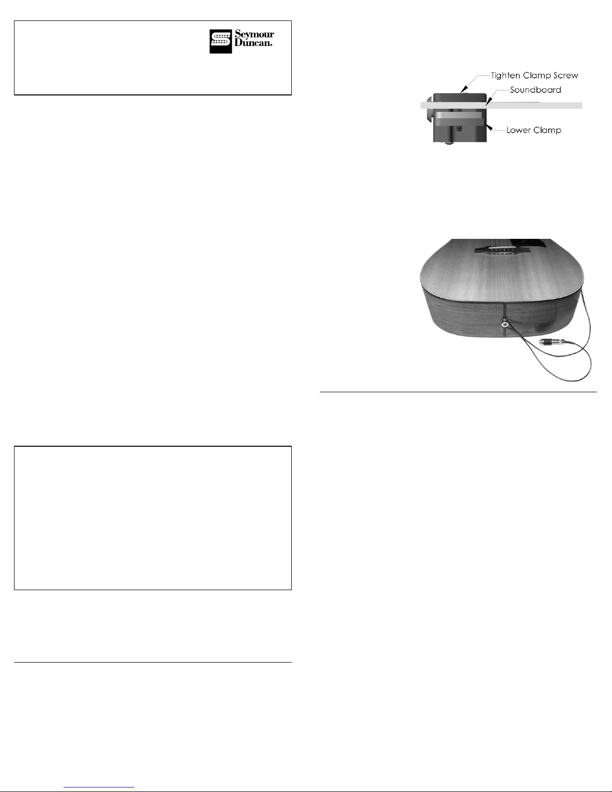
4) On the pickup unit itself, make sure that the clamps are open wide enough to accept
the soundboard (refer to Fig.1).
Figure 1
5) Insert both the battery holder (with the battery in the clip) and the pickup into
the soundhole.
6) Stick the battery holder to the Velcro installed in step 3.
7) Slide the pickup into place on the neck-side of the soundhole.
8) Tighten the screws to clamp the pickup securely in place.
(Warning: over-tightening can compress the foam padding and mar your guitar top).
9) Allow the cable to exit from the soundhole and use the strain relief attachment loop
to secure the cable and female jack to the end pin on your guitar
(refer to Fig.2).
Figure 2
10) Reinstall your strings, plug any standard 1/4" guitar
cable or patch cord into the female jack and you’re good to go!
Permanent Installation
This consists of basically two steps:
1) Drilling the hole for the end pin jack (this step is best done by a qualified
repairperson or luthier, for whom it is a common procedure. Common sense dictates
that any time you take a drill to your instrument, if you’re not 100% sure of your
abilities, you’ll let someone more qualified handle this step).
2) Installing the end pin jack, pickup and battery.
Tools you will need:
Variable Speed Hand Drill
1/4", 13/32", 7/16" and 15/32" Twist Drill bits
1/2" Tapered Reamer
Low Tack Masking Tape
Precision Saw (X-Acto saw, small coping saw, fine tooth hacksaw, etc.)
Center punch
1) Remove the strings.
2) If possible, remove the end pin, do not use excessive force. On some guitars it will
be necessary to remove a screw first. There are even a few guitars in which the end
pin itself is threaded in and will need to be unscrewed. If you are successful, proceed
directly to Step 6. If the end pin can not be easily removed, proceed with step 3.
3) Apply low tack masking tape to the surface of the guitar around the area of the
end pin. This will help protect the finish.
4) Use the precision saw to remove the end pin about 1/16" above the body. If the
end pin is fastened with a screw, remove the screw first.
5) Centerpunch the end pin stub and drill a 1/4" pilot hole through the end pin and
endblock.
6) Use the reamer to ream out the hole. Continue working until the outside of the hole
reaches 1/2" diameter.
7) Drill the inner, tapered portion of the hole to the final diameter in progressively
larger steps using the 13/32", 7/16" and 15/32" drill bits. Be careful to keep the drill
perpendicular to the body and use slow, even pressure. Do not remove the drills from
the hole until the rotation has fully stopped.
Continued on reverse side...
Mag Mic
™
ACOUSTIC PICKUP SYSTEM
Controls
Master Volume – as the name implies, this controls the volume of both the magnetic
and microphone. The magnetic pickup is always on. Important note: The master
volume control is the dial closest to the low e-string, and the Mic volume control is
located closest to the high e-string. People often confuse these two controls because
of the circuit board labels on the bottom of the pickup which read 'output' and 'mic'.
Although these labels are located directly beneath the controls, the labels do not
correspond to the controls. If you confuse the two controls, it will appear as though
the mic is working, and the magnetic pickup is not.
Microphone Volume – this allows you to regulate any amount of microphone
signal from 0% to 100% depending on your tonal needs and feedback considerations.
Blending is accomplished on-board and the output signal contains a mix of the
pickup and microphone. This eliminates the needs for any off-board blender systems.
A C O U S T I C
Page 2
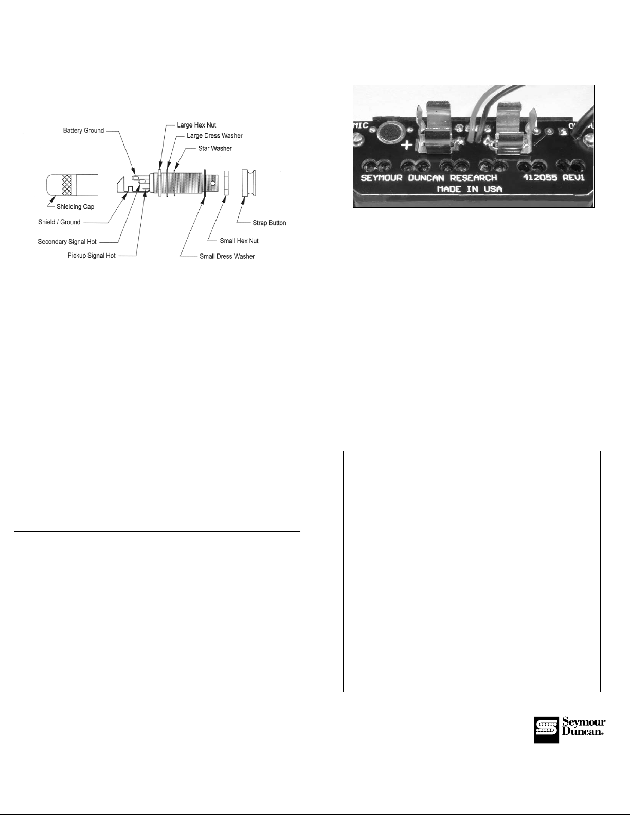
1) Lay the pickup upside down on a flat surface. Locate the two pairs of solder pads
that the battery clips will be mounted to.
2) Press the mounting tabs on the bottom of the battery clips into the appropriate holes
in the PCB that serves as the bottom cover. Be sure that the dimpled tabs that contact
the battery are both oriented toward the outside edges of the pickup (refer to Fig.4).
Figure 4
3) Tin the solder iron tip and lay it on the inside bottom of one of the clips.
Heat the clip at one end until you are able to smoothly flow solder in between the clip
and the solder pad. Move the soldering iron to the other end of the clip and solder
again. Repeat the process for the second clip.
4) Check your solder job, all joints should look smooth and shiny (not lumpy and
gray). These solder joints are all that is mechanically holding the battery clips in place.
5) It is optional to cut the 9-volt battery holder off – your choice.
6) Installation of the pickup into the guitar is the same as either of the two previously
described methods, depending on whether you desire a permanent or non-permanent
installation of the end-pin jack.
When to Change to Battery
With hard plucking of notes, you will notice distortion on the attack of the note.
When this occurs, your battery is starting to get low. At this point, you’ll get at least 20
hours of use before it dies completely (four with the “N” battery). However, you should
change the battery at this point in order to preserve the great tone of the pickup.
Keep in mind that the “N” battery clips are secured to the PCB by the solder joint
only. Not to overly stress this point, but please take care when changing the
battery.
Seymour Duncan Acoustic
5427 Hollister Avenue
Santa Barbara, CA 93111-2345
Phone: 805-964-9610 Fax: 805-964-9749
www.seymourduncan.com
Hand built in Santa Barbara, California. Velcro is a registered trademark of Velcro Industries B.
Specifications
Magnetic pickup
DC Resistance – 3.8K Ohms
Resonant Frequency – 16KHz
Gauss Strength – 780 max (adjustable)
Microphone capsule
Pattern – Omni-directional
Sensitivity - -35dB
Frequency range – 20 to 20KHz
S/N ratio - >62dB
Current consumption – 0.5mA
Onboard electronics
2 Channels, summed at the output
Supply Voltage – 9Vdc
Current consumption – 1.1mA (preamp + mic capsule)
Battery Life – 450+ hours
Maximum signal swing – 1.5V @ onset of clip w/9V power supply
Thd – 0.02% @ onset of clipping
Noise:
·Pickup channel – -102dBV with 5K ohm source impedance
·Mic channel – -96dBV with mic capsule attached
Installing the end pin jack, pickup and battery
Tools you will need:
1/2" Open End Wrench
3/32" Allen Wrench
#2 Phillips screwdriver
String winder (optional)
Small lint-free cloth
Rubbing alcohol
1) Remove the strap button, small dress hex nut, and small dress washer from the
female jack; and then remove the black plastic sleeve.
2) From the inside (cable side) of the guitar, keep the large hex nut, large dress washer
and star washer on the interior side of the jack and slide it through the end pin hole.
The jack should protrude from the outside surface between 5/16" and 11/32". If it is
not within this range, it must be removed and the position of the large hex nut adjusted
accordingly.
3) Install the small dress washer and the smaller hex nut. Hold the jack in place with
the allen wrench and use the 1/2" open end wrench to tighten the nut.
4) Screw on the strap button and hand tighten.
5) Clean the neck block to ensure that it’s free from sawdust, oils or any debris –
this can be done with a cloth moistened with rubbing alcohol (be careful not to get any
alcohol on the finish of your guitar).
6) After the alcohol is dry, apply one half of the Velcro® to the neck block where you
wish to affix the battery holder.
7) Insert both the battery holder (with the battery in the clip) and the pickup into the
soundhole.
8) Stick the battery holder to the Velcro installed in step 2.
9) On the pickup unit itself, make sure that the clamps are open wide enough to accept
the soundboard.
10) Slide the pickup into place on the neck-side of the soundhole.
11) Tighten the screws to clap securely (warning: over-tightening can compress the foam
padding and mar your guitar top).
12) Reinstall strings and plug in a standard 1/4" guitar cable to the end pin jack and
you’re done.
13) Make great music!
Installation (Using “N” Battery)
By installing the “N” battery clips, the Mag Mic becomes a single, integrated unit for
the ultimate in portability. However, this entails some compromises. Battery life is
severely limited: you’ll get 50 hours with an “N” battery as opposed to 450 with a
standard 9 volt. Also, when inserting an “N” battery, you must ensure that it’s
polarized correctly. The positive end of the battery must be oriented toward the “plus”
symbol next to the microphone on the underside of the pickup (refer to Fig.4).
Installing the “N” battery clips is a tricky process and requires high-level soldering
abilities and a good quality iron with the correct tip. It is essential that the work be
done properly. Even when done perfectly, the clip will still not stand much abuse.
It is advisable that care be used when installing and changing batteries. If you’re not
entirely confident that you posses these abilities, please have this procedure done by
a qualified electronics technician. Here are the steps:
Installation of Clips
Tools you will need:
50 watt, pencil type soldering iron with medium, spade type tip
Rosin core solder
PN# 501050-105 Rev B
A C O U S T I C
 Loading...