

Page 1
Owners Manual
Pt. No. 67304
Issue 1217
Head Office:
P.O. Box 2018
Hilton Highway, Washdyke
Timaru, New Zealand
Telephone (03) 688 2029
Facsimile (03) 688 2821
Australian Branch:
4B Silverton Close
Laverton North 3026
Melbourne, Australia
Telephone (03) 9314-9666
Facsimile (03) 9314-6810
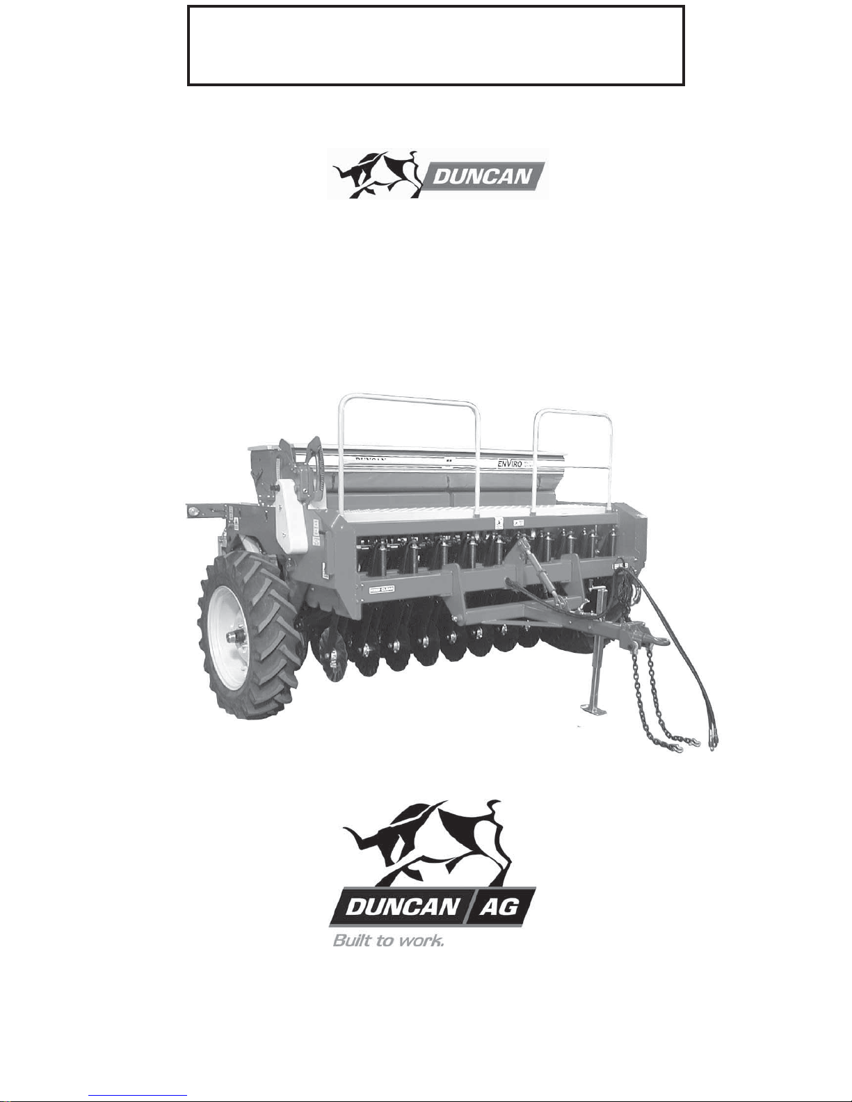
‘Enviro’ Seed Drill
Model 740
Page 2

Page 3

‘Sidewinder’ Hayfeeder Contents
Page
Introduction Description of Machine . . . . . . . . . . . . 3
Working Principle. . . . . . . . . . . . . . . . . 5
Acquisition & Warranty . . . . . . . . . . . . . . . . . . . . . . . . . . . . . . . . 7
Specification . . . . . . . . . . . . . . . . . . . . . . . . . . . . . . . . 7
Safety General Cautions. . . . . . . . . . . . . . . . . 7
Transport . . . . . . . . . . . . . . . . . . . . . . . . . . . . . . . . 8
Operation Connections. . . . . . . . . . . . . . . . . . . . . 9
Loading Hay. . . . . . . . . . . . . . . . . . . . . 10
Feeding Out. . . . . . . . . . . . . . . . . . . . . 11
Cautions Specific to Machine . . . . . . . 12
Calibration Charts . . . . . . . . . . . . . . . . . . . . . . . . . 13
Descriptions & Photos . . . . . . . . . . . . . 11
Adjustments Machine Settings . . . . . . . . . . . . . . . . . 15
Maintenance Lubrication Chart . . . . . . . . . . . . . . . . . 11
Servicing . . . . . . . . . . . . . . . . . . . . . . . 13
Mechanical Adjustments . . . . . . . . . . . 14
Special Adjustments . . . . . . . . . . . . . . 15
Storage . . . . . . . . . . . . . . . . . . . . . . . . . . . . . . . . 16
Parts Lists . . . . . . . . . . . . . . . . . . . . . . . . . . . . . . . . 17
Dealer & Service Information . . . . . . . . . . . . . . . . . . . . . . . . . . . . . . . . 31
‘Enviro’ Seed Drill Contents
Page
Introduction . . . . . . . . . . . . . . . . . . . . . . . . . . . . . . . . . . . . . . 2
Acquisition & Warranty . . . . . . . . . . . . . . . . . . . . . . . . . . . . . . . . . . . . . . 2
Disclaimer . . . . . . . . . . . . . . . . . . . . . . . . . . . . . . . . . . . . . . 2
Description of Machine Working Principle. . . . . . . . . . . . . . . . . . . . . . . 3
Specification . . . . . . . . . . . . . . . . . . . . . . . . . . . . . . . . . . . . . . 3
SAFETY - General Safety Symbols on Machine . . . . . . . . . . . . . . 4
Operator Safety. . . . . . . . . . . . . . . . . . . . . . . . 5
Be Prepared for Emergencies. . . . . . . . . . . . . 5
Appropriate Dress . . . . . . . . . . . . . . . . . . . . . . 6
Transport This Machine Safely . . . . . . . . . . . . 6
Handle Agricultural Chemicals Safely. . . . . . . 7
Avoid High Pressure Fluids. . . . . . . . . . . . . . . 7
Safe Work Practices . . . . . . . . . . . . . . . . . . . . 7
Practise Safe Maintenance . . . . . . . . . . . . . . . 8
SAFETY - Machine Specific Hazard Points . . . . . . . . . . . . . . . . . . . . . . . . . 9
Safety Decals & Safety Guards. . . . . . . . . . . . 11
Transport Preparation and Towing on the Road . . . . . . . 12
Operation General Operation Guidelines. . . . . . . . . . . . . 13
Sowing Speed . . . . . . . . . . . . . . . . . . . . . . . . . 13
Front Coulter & Dragbar Loading . . . . . . . . . . 13
Transport Position . . . . . . . . . . . . . . . . . . . . . . 14
Coulter Penetration Depth. . . . . . . . . . . . . . . . 14
Double Disc Sowing Depth . . . . . . . . . . . . . . . 14
Press Wheel Adjustment. . . . . . . . . . . . . . . . . 14
Double Disc Scrapers . . . . . . . . . . . . . . . . . . . 14
Press Wheel Scrapers. . . . . . . . . . . . . . . . . . . 15
Level Drill. . . . . . . . . . . . . . . . . . . . . . . . . . . . . 15
Sowing Charts . . . . . . . . . . . . . . . . . . . . . . . . . . . . . . . 16
Basic Calibration Procedure Gearbox Setting Lever. . . . . . . . . . . . . . . . 17
Selecting the Gear Ratio. . . . . . . . . . . . . . . . . 17
Setting Seeder Shutter Slides. . . . . . . . . . . . . 17
Bottom Flap Settings. . . . . . . . . . . . . . . . . . . . 17
Seed Calibration Procedure . . . . . . . . . . . . . . 18
Hand Crank Turns for Seed Rate Calibration . 19
Calculating Crank Turns for Other Widths . . . 19
Recalculating the Constant . . . . . . . . . . . . . . . 20
Use of Seed Rate Calculator. . . . . . . . . . . . . . 20
Calibration Deviations . . . . . . . . . . . . . . . . . . . 21
Hints for Sowing with Variable Speed Gearbox 22
Sowing of Fine Seeds. . . . . . . . . . . . . . . . . . . 22
Small Seed . . . . . . . . . . . . . . . . . . . . . . . . . . . 23
Sowing Peas . . . . . . . . . . . . . . . . . . . . . . . . . . 23
Hectaremeter Settings. . . . . . . . . . . . . . . . . . . 24
Calibration Notes. . . . . . . . . . . . . . . . . . . . . . . 25
Maintenance & Care General . . . . . . . . . . . . . . . . . . . . . . . . . . . . . . 26
General Cautionary Maintenance Advice . . . . 26
Lubrication Chart. . . . . . . . . . . . . . . . . . . . . . . 27
Maintenance Schedule . . . . . . . . . . . . . . . . . . 27
Storage . . . . . . . . . . . . . . . . . . . . . . . . . . . . . . 30
Maintenance Notes . . . . . . . . . . . . . . . . . . . . . 31
Parts Lists . . . . . . . . . . . . . . . . . . . . . . . . . . . . . . . . . . . . . . 33
Page 4

2
Introduction
Acquisition & Warranty
On delivery of your new Duncan Enviro Seed Drill please
check that the machine is not damaged. In cases of shipping
damage, please ask your dealer to arrange for the appropriate
claim to be lodged immediately. Assemble any parts supplied
loose and inspect your machine with the aid of this manual to
familiarise yourself with its features. If you have any queries
ask your dealer straight away. The machine is covered by our
12 month warranty on faulty parts, subject to normal use.
Record below the serial number of your machine and keep
it in a secure place to help trace the machine and assist
us when you order parts.
The Owner’s Manual
Your new Duncan Enviro Seed Drill will give long and efficient
service if given normal care and operated properly.
This owner’s manual is provided so that you can become
thoroughly familiar with the design of the machine and to
furnish information on correct operation, adjustment and
maintenance. Only persons well acquainted with these
guidelines should be allowed to use the equipment.
A separate illustrated parts section has been provided so that
if any parts are required your dealer will be able to supply
them by reference to part numbers.
The manual is considered as part of your machine and must
remain with the machine when it is sold.
Right and left hand references in this manual are
determined by standing behind the machine and facing in
the direction of travel.
Disclaimer
Every effort has been made to
ensure that the information in this
manual was accurate and up to
date at the time of going to press.
Clough Agriculture reserves the
right to make subsequent changes
to the machine, where necessary,
without notification.
The Company will not be
responsible for any damage or
consequential loss arising out of
misinterpretation or failure to follow
recommended procedures. Nor will
it be liable for any damage caused
by or arising out of modification or
misuse of its product.
The owner has a responsibility to
protect himself and others by
observing all safety information
and by ensuring all operators are
well acquainted with the safety
information, trained in the correct
use of the machine and applying
safe work practices.
Model: . . . . . . . . . . . . . . . . . . . . . . . . . . . . . . . . . . . . . .
Serial No:. . . . . . . . . . . . . . . . . . . . . . . . . . . . . . . . . . .
Owner:. . . . . . . . . . . . . . . . . . . . . . . . . . . . . . . . . . . . . .
. . . . . . . . . . . . . . . . . . . . . . . . . . . . . . . . . . . . . . . . . . . . .
. . . . . . . . . . . . . . . . . . . . . . . . . . . . . . . . . . . . . . . . . . . . .
Delivery Date:. . . . . . . . . . . . . . . . . . . . . . . . . . . . . . .
Dealer:. . . . . . . . . . . . . . . . . . . . . . . . . . . . . . . . . . . . . .
. . . . . . . . . . . . . . . . . . . . . . . . . . . . . . . . . . . . . . . . . . . . .
. . . . . . . . . . . . . . . . . . . . . . . . . . . . . . . . . . . . . . . . . . . . .
Page 5
3
Pt. No. 67304
Issue 1217
Description of Machine
The Duncan ‘Enviro’ is a triple disc direct drill.
It has two boxes for either seed combinations
or traditional seed fertiliser mixes. The
boxes are mounted on a heavy duty frame
accommodating large end wheels which are
hydraulically operated allowing adjustable
sowing pressure and good transport
clearance. Both disc opener and double disc
are independently sprung allowing good
contour following ability. Sowing depth is
controlled by adjustable rubber tyred depth
wheels. The quality European type peg roller seeder
system handles all seeds from turnip and rape through
to peas and maize. The seeder drive is via a clutch
and variable speed gearbox from the drive wheels.
For transport the drive is easily disconnected using a
freewheeling type hub fitted to the drive wheel.
Working Principle
The gearbox, pegged seed rollers and seeder flaps are set
to give the desired seed rate. The front disc pre-cuts the
surface followed by the double disc creating the seed bed.
Seed/fertiliser flows down the flexible convolute tubes between
seeder and double disc units dropping into the prepared seed
bed. A suitably profiled depth wheel maintains the double discs
at a predetermined depth and closes and compacts the soil
over the deposited seed.
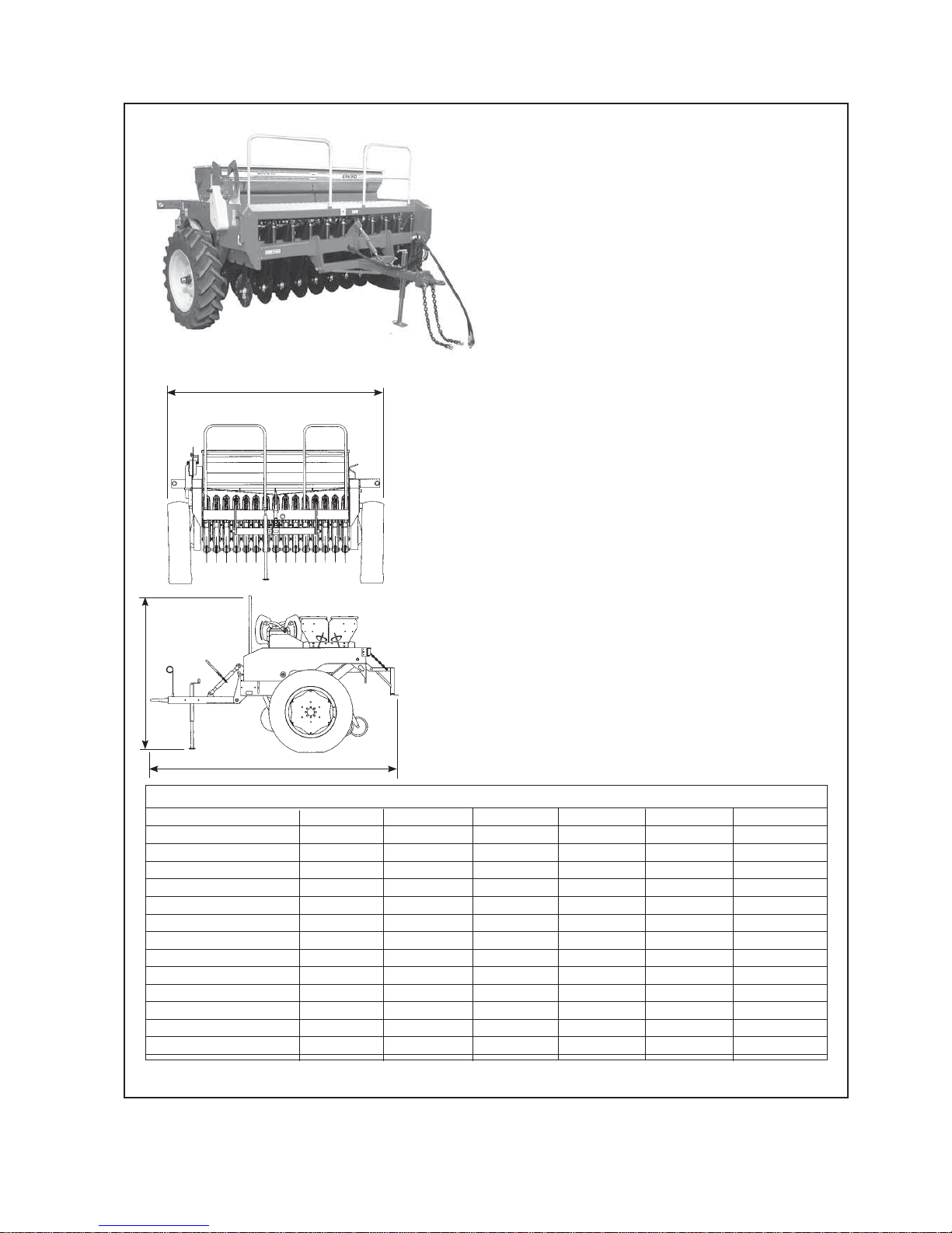
Dimensions & Capacities
15 Run 17 Run 19 Run 21 Run 23 Run 26 Run
Width (Over Wheels) 3280 3280 3880 3880 4644 4644
Overall Length 3770 3770 3770 3770 3770 3770
Height (Transport Max) 2290 2290 2290 2290 2290 2290
Weight (Unladen) * 2730kg 3080kg 3485kg 3850kg 4200kg 4725kg
Tyre Size
12.4/11 x 28 x 12 ply 2 2 2 2 2 2
Maximum Speed 30kph 30kph 30kph 30kph 30kph 30kph
Tyre Pressure 1.8bar(25psi) 1.8bar(25psi) 1.8bar(25psi) 1.8bar(25psi) 1.8bar(25psi) 1.8bar(25psi)
Row Spacing 150 130 150 130 150 130
Press Wheel Options 2”, 3” or 4” 2” or 3” 2”, 3” or 4” 2” or 3” 2”, 3” or 4” 2” or 3”
Sowing Width 2.25m 2.21m 2.85m 2.84m 3.45m 3.38m
Box Capacity (Per box) 348 litres 348 litres 443 litres 443 litres 537 litres
537 litres
Overall Length
(Refer Table)
Width (Over Wheels)
(Refer Table)
Height (Transport Max)
(Refer Table)
* Weights are approximate only
Page 6

4
Do not ride or allow passengers on the machine.
Under no circumstances are passengers to be permitted
on the machine while it is in operation or being transported.
Any footboards and/or footsteps are provided solely for the
purpose of preparing the machine for use.
Keep clothing and body extremities well clear of pinch
points while the machine is operating (seeding or
calibrating). Keep well clear of moving parts at all times.
These signs typically occur wherever trapping points exist.
These include drive chains, sprockets, shafts, wheels, discs,
pivot points, etc. Guards are provided with the machine
for safety reasons (where practical without compromising
machine performance). Ensure these are always fitted during
operation.
Always exercise extreme caution in the vicinity of sharp
edges and points.
Where possible guards are provided with the machine
for safety reasons (where practical without compromising
machine performance). Ensure these are always fitted during
operation.
Footboards, footsteps, drawbars and other machine
surfaces may be slippery when wet.
Apply extra caution in wet conditions and in the early morning
when surfaces are wet.
Keep Clear. (It is dangerous to be in this area when the
machine is operating.)
!
ATTENTION
On the machine important safety information is indicated by these symbols.
These highlight general safety aspects in regard to the machine rather than specific hazards.
Page 7
5
Pt. No. 67304
Issue 1217
SAFETY - General
This section of the manual offers general guidelines
for the safe operation of machinery. It does not replace
local safety regulations.
These guidelines were current at
the time of publication, but may be superseded by later
regulations.
Clough Agriculture has made every effort to highlight all
risks to personnel or property. Owners and operators have
a responsibility to exercise care and safe work practices at
all times in the vicinity of the machine.
Owners are advised to keep up to date on safety issues
and to communicate these to all users of the machine.
Contact the Occupational Safety and Health Service
(OSH) for further information about general safety aspects.
If you have safety concerns specifically related to this
machine, contact your dealer immediately.
Operator Safety
Read this manual carefully before operating new
equipment. Learn how to use this machine safely.
Be thoroughly familiar with the controls and the proper use
of the equipment before using it.
Take careful note of all safety instructions both in this
manual and on the machine itself. Failure to comply with
instructions could result in personal injury and/or damage
to the machine.
Replace missing or damaged safety signs on the machine
and ensure that these remain clearly visible.
It is the owner’s responsibility to ensure that anyone
who operates, adjusts, lubricates, maintains, cleans
or uses the machine in any way has had suitable
instruction and is familiar with the information in this
manual (particularly with regard to safety aspects).
Operators and other users of the machine should be
aware of potential hazards and operating limitations.
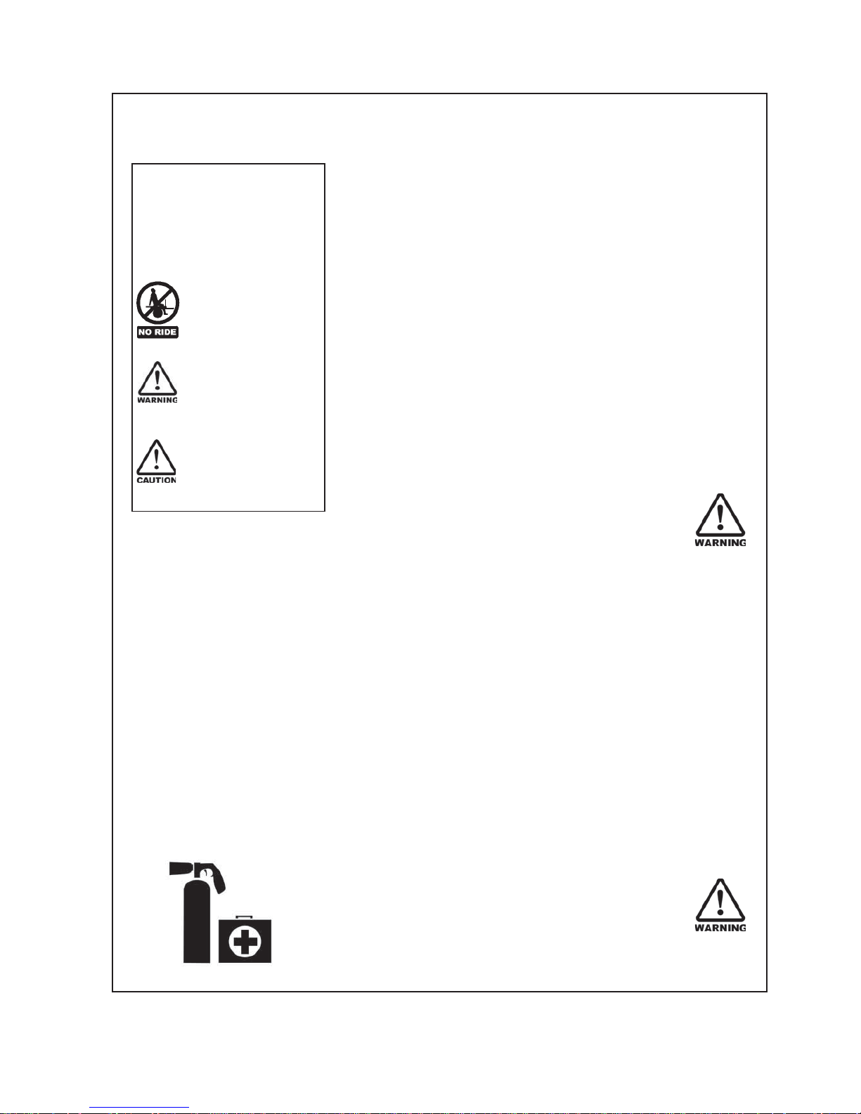
Be Prepared for Emergencies
Keep a first aid kit and fire extinguisher handy.
Keep emergency numbers for doctors, ambulance,
hospital and fire department near your telephone.
N.B. Throughout this
manual important safety
information is indicated
by these symbols in the
margin:
A prohibition should
be observed under all
circumstances.
A warning indicates
a hazard that could
cause death or injury if
the warning is ignored.
A caution indicates a
hazard that may cause
damage to property if
the caution is ignored.
Page 8

6
SAFETY - General (Continued)
Appropriate Dress
Wear close fitting clothing and avoid rings or other forms of
jewellery which could become caught in the machinery.
People with long hair must have it securely fixed and confined
close to the head.
Refer to local safety standards for protective clothing and
recommended safety equipment.
Transport This Machine Safely
Ensure that all linkage pins and security clips are fitted correctly.
With trailing machines tow with the drawbar only, as this is the
only safe towing point on the machine.
Always check that bystanders (especially children) are well clear
(front and rear) before starting and moving the tractor and the
machine.
Plan safe routes of travel, and be aware of power lines and
other roadside hazards. Take particular care when towing
implements on hillsides.
Do not ride or allow passengers on the machine.
This machine is not designed to carry passengers, and no riders
are permitted.
Road transport
On public roads,
• A speed of 30km/h must not be exceeded.
• Do not operate during the hours of darkness unless standard
lights are fitted and clearly visible. (This also applies when
visibility is limited, e.g., in foggy conditions.)
See the guidelines in the Vehicle Dimensions and Mass Rule,
issued by the Land & Transport Safety Authority.
Avoid tip-overs
Avoid holes, ditches and obstructions which may cause the
machine to tip over, especially on hillsides. Never drive near the
edge of a gully or steep embankment - it might cave in. Slow
down for hillsides, rough ground and sharp turns.
Page 9
7
Pt. No. 67304
Issue 1217
SAFETY - General (Continued)
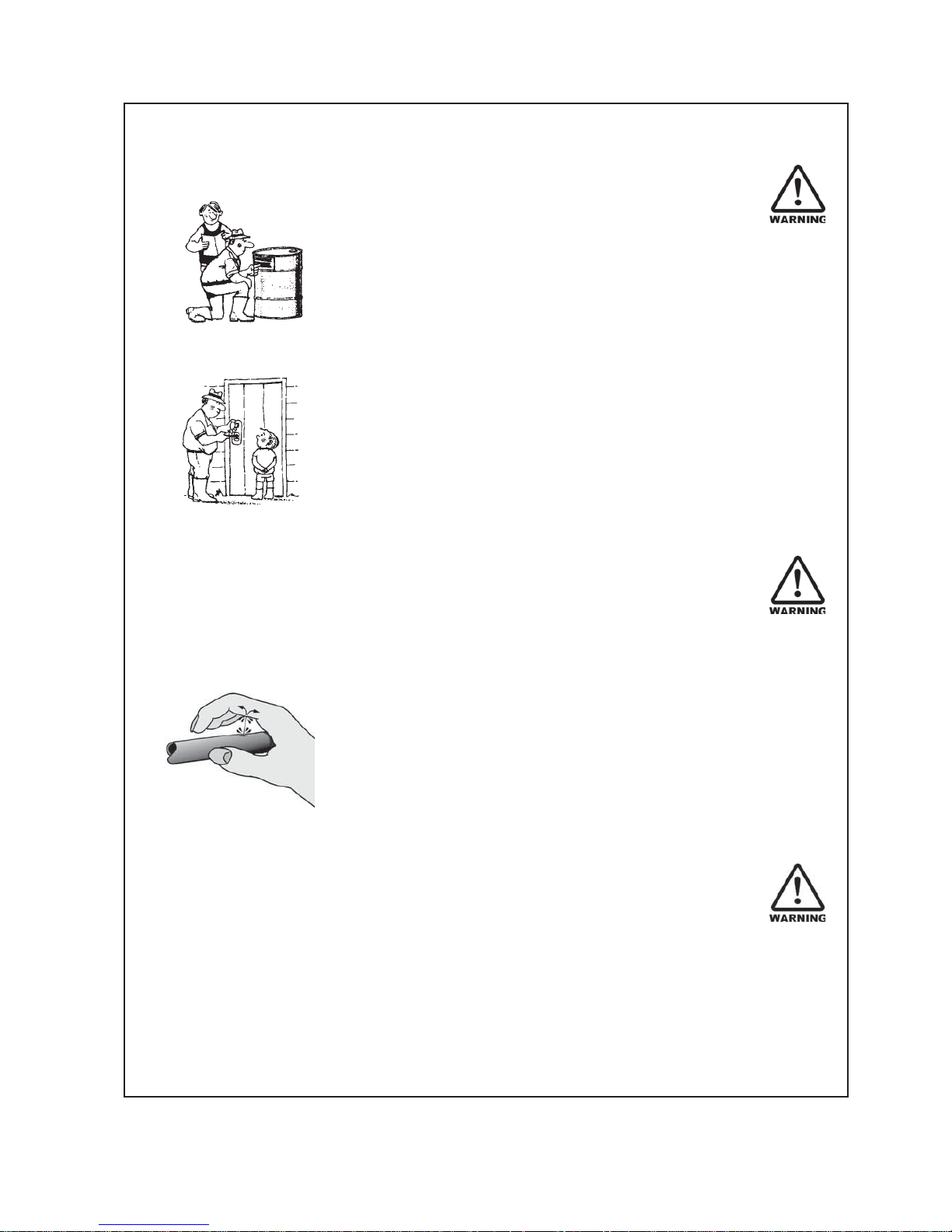
Handle Agricultural Chemicals Safely
All farm chemicals should be stored, used, handled and
disposed of safely and in accordance with the supplier’s/
manufacturer’s recommendations.
Read the product label before using, noting any warnings
or special cautions, including any protective clothing or
equipment that may be required, ie. respirtor.
Do not eat or smoke while handling sprays, fertilisers, coated
seeds, etc. Afterwards, always wash your hands and face before
you eat, drink, smoke, or use the toilet.
Store sprays, fertilisers, coated seeds, etc. out of reach of
children and pets, and away from food and animal feeds.
Any symptoms of illness during or after using chemicals
should be treated according to the supplier’s/manufacturer’s
recommendations. If severe, call a physician or get the patient
to hospital immediately. Keep the container and/or label for
reference.
Avoid High Pressure Fluids
Avoid any contact with fluids leaking under pressure, because
the fluids can penetrate the skin surface.
Any fluid which penetrates the skin, will need to be removed
immediately by a medical expert. Seek specialist advice on
this type of injury.
Relieve the pressure before disconnecting any hydraulic or other
lines. Make all repairs and tighten all fittings before
re-connection to pressurised fluid.
Keep your hands and body away from any pinholes or high
pressure jets. Search for leaks with a piece of cardboard instead
of using your hand directly.
Safe Work Practices
All farm machinery is potentially dangerous and should be
treated with caution and respect.
Before starting the machine, ensure that all controls are placed
in neutral and that bystanders are well clear. Check that the
guards have been securely fitted and that any adjustments have
been made correctly.
Where possible, disconnect or isolate the drive mechanism to the
implement. Lower the machine onto the ground when not in use.
Page 10

8
SAFETY - General (Continued)
Practise Safe Maintenance
Keep the machine in safe working condition. Routine
maintenance and regular servicing will help reduce risks and
prolong the life of the machine.
General Maintenance
Accidents occur most frequently during servicing and repair.
The following general rules must be followed when maintaining
or working with machinery:
• All operating and maintenance manuals must be read
before and referred to while using or servicing any piece of
equipment.
• Turn off all machinery power sources and isolate the
machine before making adjustments, doing lubrication,
repairs or any other maintenance on the machine.
• Ensure that the machine hydraulics are disconnected from
the power source.
• Wear gloves when handling components with cutting
edges, such as any ground cutting components.
• Beware of hazards created by springs under tension or
compression when dismantling or maintaining the
machine.
• It is recommended that you clean the machine with a water
blaster or similar apparatus before commencing
maintenance.
Make Sure the Machine is Well Supported
When machinery is fitted with hydraulics, do not rely on the
hydraulics to support the machine. During maintenance or
while making adjustments under the machine, always lock the
hydraulics and support the machine securely. Place blocks or
other stable supports under elevated parts before working on
these.
Electrical Maintenance
Disconnect the electrical supply from the tractor before doing
any electrical maintenance.
Welding
With electronic equipment in modern tractors it is advisable to
disconnect the machine from the tractor, or at least disconnect
the alternator and battery before attempting any welding.
Use Only Genuine Spare Parts
Unauthorised modifications or non-genuine spare parts may be
hazardous and impair the safe operation and working life of the
machine.
Excess lubricants must be disposed of safely so as not to
become a hazard.
Page 11

9
Pt. No. 67304
Issue 1217
SAFETY - Machine Specific
This section of the manual gives specific guidelines for
the safe operation of the Duncan Enviro.
These guidelines were current at the time of publication, but
may be superseded by later circumstances. They do not
necessarily cover every possible hazard and must be read in
conjunction with the SAFETY - General section (Page 4 - 8).
Hazard Points on the Duncan Enviro
The lists below are not all-inclusive and serve only to highlight
the more obvious areas of risk.
The decals attached to the machine are a general reminder
that there are hazardous areas on the machine, rather than
specifically highlighting all possible hazards.
For decal locations on machine, refer Page 11.
No Ride
Passengers are not permitted anywhere on the machine.
Pinch Points/Moving Parts
Hazardous areas include:
• Drive chains.
• Sprockets between the drive wheel, the clutch shaft and
the gearbox (RH side).
• Sprockets between the gearbox and the box shafts
(RH side).
• Agitator drive units (LH side) provided with top cover plates.
• Agitator shaft inside the boxes.
• Seeder units, box shaft and shaft connectors.
• Adjacent dragbars and coulter arms.
• Between double discs and other sub-assembly parts.
• Wheel legs and side frame assemblies.
• Dragbar springs, spring rods and pressure bar.
• Press wheel assemblies.
Slippery When Wet
Hazardous areas include:
• Footboards and footstep.
• All smooth surfaces on the frame structure.
Keep Clear
Hazardous areas include:
• Between the tractor and Duncan Enviro.
• Immediately adjacent to the Duncan Enviro side.
Page 12

10
SAFETY - Machine Specific
(Continued)
Hazard Points on the Duncan Enviro
(Continued)
Chain Guards & Access Covers
To prevent hands, etc. getting caught in the gearbox drive
chain, a guard is provided to cover sprockets, chain and chain
tensioner mounted on the side of the mainframe side plate.
A guard is also provided to cover the seedbox drive chains
at the rear of the gearbox. The metal access plates on the
side frames and the wheel legs must only be removed during
servicing. All these guards must be fitted while using the
machine.
Warning: Access to pinch points is still possible from
underneath the machine.
For guard locations on machine, refer Page 11.
Calibrating
Be particularly careful when calibrating the seeding rate. At
this time, the calibration trays have been removed and are no
longer covering the rotating seeder units. See Pinch Points/
Moving Parts (Page 9) for hazardous areas.
Transport
The two large wheels located at the sides of the machine are
for the purpose of controlling maximum loading on dragbars
and coulters and gearbox input drive (RH wheel). These are
also used to support the machine weight during transport
(while linked to the tractor).
Important - Refer to safety cautions in the Transport section,
Page 13 of the manual.
Ensure that all linkage pins and security clips are fitted
correctly.
Maintenance
Refer Page 26 - 30 for the Care and Maintenance section of
the manual.
Lubrication
Refer Page 27 for the Lubrication section of the manual.
Page 13
11
Pt. No. 67304
Issue 1217
SAFETY - Machine Specific
(Continued)
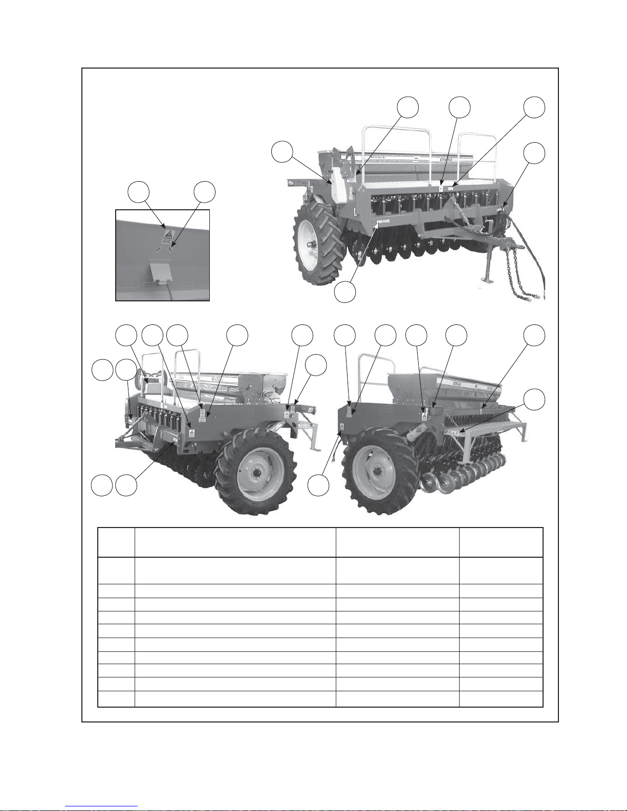
Safety Decals
& Safety Guards
Item Decal/Guard Cross Reference Pt No Qty.
1 ‘No Ride’ (75x99) Refer Page 9 43906 2
2 ‘Pinch Point/Moving Parts’ (75x99) Refer Page 9 43907 4
3 ‘Slippery When Wet’ (100x45) Refer Page 9 43902 3
4 ‘Keep Clear’ (38x192) Refer Page 9 43909 2
5 ‘Pinch Point/Moving Parts’ (50x66) Refer Page 9 43901 2
6 Arrows 43905 4
7 Plastic Guard (Clutch to Gearbox) Refer Page 10 22743 1
8 Fibreglass Guard (Gearbox to Seedbox) Refer Page 10 22527 1
9 Attention: Check Wheel Nuts Regularly 43708 2
10 Don’t Use Wheel As Step 43709 4
11 ‘30 km/hr’ 43914 2
842
10 10
9 2
10
1
3
2
4
29
7
3
4
5
10
4
6
18
Inside Box Lid
Table 2
11
11
Page 14
12
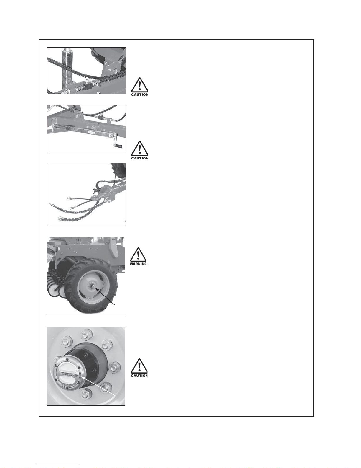
Transport
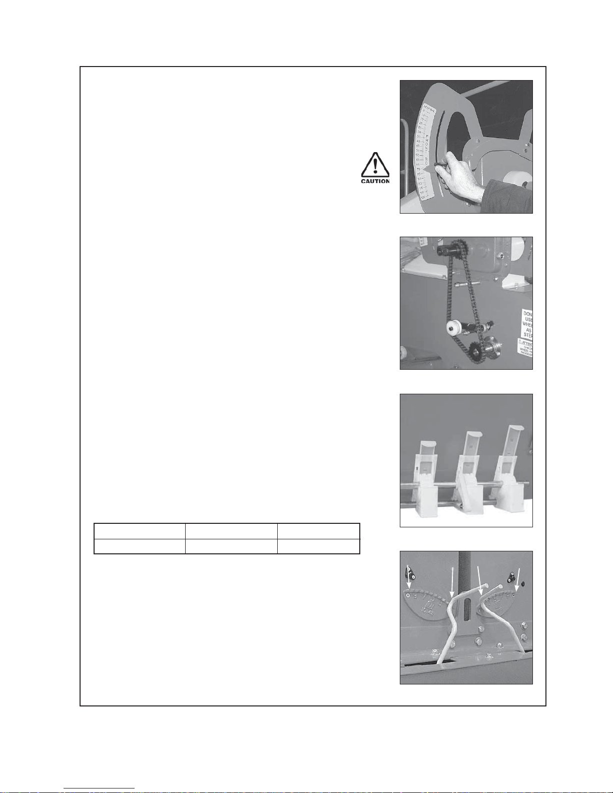
1 Raise the drill into the transport position and hold at
the full extent of the rams for a few seconds to allow
cylinders to rephase/equalise.
2
Important - To avoid machine damage due to drill
lowering during transport, always close the hydraulic
valve on the drawbar. Move the handle to a position at
90
0
to the hydraulic line as shown in Fig 1.
3 Locate jack stand in transport position. Refer Fig 2.
4 Ensure lighting and oversize warning requirements meet
recommendations published by the local Land Transport
Authority or equivalent.
5
Maximum towing speed 30 km/hr.
For countries other than New Zealand greater speed
restrictions may apply, please refer to your local
transport authority.
Ensure towing vehicle requirements are adequate
for the towed vehicle e.g. mass, brakes. Refer to
recommendations published by the local Land Transport
Authority or equivalent.
Braking when towing can cause the load to jackknife.
Use extra care when towing in adverse conditions such
as mud, inclines and sharp bends.
Lower towing speeds are recommmended on farm
roads/tracks and where one wheel is on or over a road
verge.
6
Attach safety chains to tractor. Refer Fig 3.
Safety chains must be crossed over underneath the
coupling and attached to the towing vehicle. The
attachment points must be as close as practical to the
towing coupling and one each side.The towbar on the
towing vehicle must be rated for the towed mass. Do not
remove or replace the safety chains provided with
any other than those specified in the parts manual.
Note: The safety chains are provided with sufficient
length to cater for all towing vehicles. Safety chains must
be shortened by cutting off excess length so that if the
coupling fails the drawbar will not hit the ground.
7 If the machine is fitted with row markers or other vertical
extensions check clearance under power lines en route.
8 Important - Before commencing towing on the road
check that the freewheeling hub positioned at the
gearbox end of the drill (Fig 4) is set to 4 x 2, not 4 x 4
which is only for sowing. Refer Fig 5. Failure to set the
freewheeling hub on 4 x 2 will result in unecessary wear
on seeder drive components and possibly damage.
fig 2
fig 5
1
fig 1
fig 3
1
fig 4
Page 15
13
Pt. No. 67304
Issue 1217
Operation
General Operation Guidelines
1 Use a sufficiently powerful tractor which is heavy enough to
tow the drill safely.
2 Operate the drill at a speed of 6-12 km/hr (4-8 mph).
In stoney and uneven ground conditions a lower speed is
more appropriate
3 Check that the drill is level during calibration and while seeding.
4 Adjust the individual depth wheels to the required sowing depth.
5 Check tyre pressure before seeding. Refer P 3.
6 Double check seed rates before seeding.
7 Raise the drill out of the ground when making any turns.
8 Raise the drill out of the ground before backing up.
9 After prolonged storage, check to see that all drive
mechanisms and hydraulic equipment are functioning correctly.
Check that the seed tubes are not perished or blocked.
Sowing Speed
Typical travel speeds when sowing range from 6-12 km/hr
in good conditions. In stoney and uneven ground conditions
a lower speed is recommended to minimise rapid part
deterioration. Sowing too fast can result in:
1 Poor contour following and uneven sowing depth.
2 Impact damage to:
a Ground engaging components.
b Bearings, housings & axles.
c Fasteners & structural components.
3 More extreme conditions will result in greater vibration &
uneven seed flow at low seeding rates.
Front Coulter & Dragbar Loading
The height of the drill when in the drilling position is
determined by the number and size of the depth collars
(1)
and the threaded depth stop
(2)
on the LH wheel arm
cylinder shaft. This in turn determines the pressure on
the discs. Refer Fig 6.
In hard or tight conditions pressure may have to
be backed off (by adding spacers) to allow positive
ground wheel drive or in very soft conditions where
downward pressure may alter seed depth. This may be
a compromise between downward pressure, good wheel
drive contact and total contour following abilities.
Caution: The actual length of the depth collars used
must be maximised to ensure that the threaded depth
stop is not damaged due to over extension.
fig 6
1
2
Page 16
14
Transport Position
When in the transport position the hydraulic cylinders are
fully extended. In this position the cylinders fully equalise
by allowing oil to bypass the master cyclinder piston. It is
recommended to raise the drill into the transport position
when turning at headlands or regularly to counteract the
effects of oil leakage past the piston and ensure cylinder
rods are equally extended and minimise variations in
sowing depth.
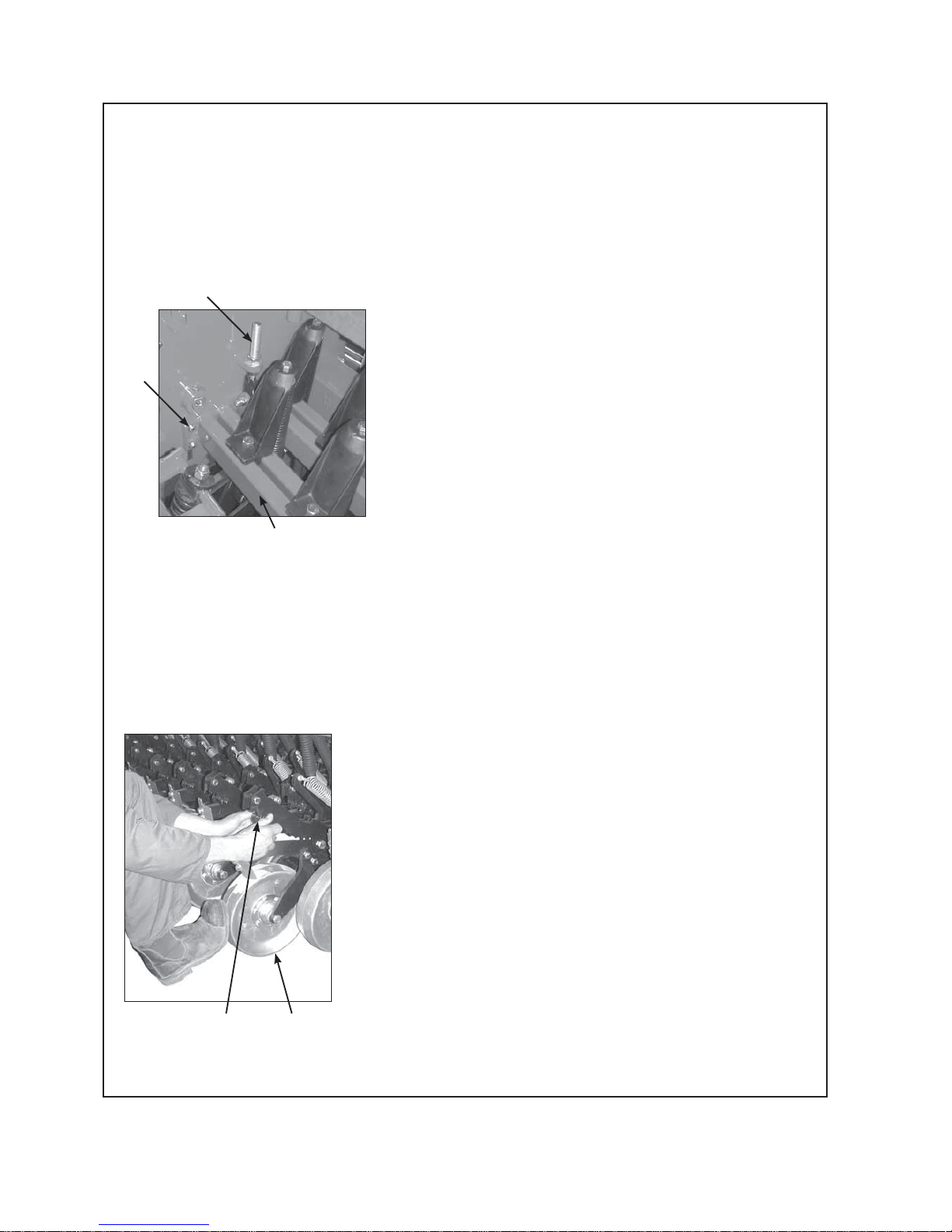
Coulter Penetration Depth
To create the ideal seed bed the front coulter should
cut approximately 20mm below the double discs. If more
undercut is required or the ground is particularly hard and
better penetration is required, the carrier beam can be
lowered by releasing the four M16 bolts
(1) at each end of
the carrier beam (2) and adjusting the coulter adjustment rod
assembly (3) See fig 7. Also refer to the maintenance section.
The carrier beam is factory set in its upper most position.
Note: The front coulter willl sharpen with initial use and
therefore penetration ability will improve.
Double Disc / Sowing Depth
The penetration depth of the double discs is dependant on
two aspects.
1 The weight applied from the machine’s mass.
2 The press wheel adjustment.
If the ground is hard and the double discs are not
penetrating to the desired depth the press wheels will
not be in contact with the ground. To increase the weight
applied refer to “Front Coulter & Dragbar Loading”.
Where the loading applied to the double discs exceeds
the ground resistance the remaining load is transferred to
the press wheels. The running height of the press wheel in
relation to the double discs controls the sowing depth. See
“Press Whel Adjustment”.
Note: Ground penetration ability will increase as the double
discs sharpen and the paint wears off.
Press Wheel Adjustment
Press wheels are used to control the seeding depth and
compact the soil after sowing to give good seed/soil
contact. To adjust the press wheel setting press down the
press wheel (1) and reposition the jaw lock pin (2) in the
desired notch. Refer fig 8.
Double Disc Scrapers
Scrapers are fitted to the rear of the double disc casting
and prevent soil buildup on the inside face of the disc.
The scrapers will need to be adjusted as the discs wear
(reduce in diameter). If not adjusted the scrapers will
overhang the disc edge and wear unevenly. Scrapers are
factory set in the correct initial operating position and don’t
require adjustment before drill use.
fig 7
fig 8
3
1
2
12
Page 17

15
Pt. No. 67304
Issue 1217
Press Wheel Scrapers
A minimum clearance of 2mm is recommended between
the scraper and the press wheel. Check the scraper
clearance on full circumference regularly as press wheels
can be eccentric. Best scraper performance may be
dependent on the ground conditions.
Level Drill
Use the drawbar turnbuckle to tilt the drill so it is sitting
level. An adjustment may be required after a short period
of use because the paint wears off the discs and the discs
sharpen which in turn improves the penetration abilities.
Page 18

16
fig 9
fig 10
‘Enviro’ Seed Drill Sowing Chart
15, 19, 23 Run (Row Spacing 150mm)
Test Seed Type/
Seed Rate (kg/ha)
Thousand Seed
Gearbox Setting Position Hints
Wgt., TSW*(gm)
H/L Position Type 15 20 30 40 50 60 70 80 90 100
Wheat (41.2) H 3/4 3 N
80.11 101.0 119.5 141.2 163.3 183.8
Oats
(37.2) H Full 3 N
77.63 96.45 114.8 134.7 154.5 172.2
Barley
(45.7) H Full 3 N
92.28 113.7 138.3 161.1 185.1 208.8
Ryecorn
(25.8) H 3/4 3 N
93.3 116.1 140.0 162.6 188.9 212.5
White Peas
(302) H 3/4 3 N
87.82 127.0 167.4 193.4 239.3 281.3 311.7 358.6
Agitator Stopped
Green Peas (240) H 3/4 3 N
69.86 106.1 140.4 173.4 210.0 250.8 285.1 319.7
Peren. Grass (2.27) H Full 3 N
5.12 10.77 21.51 32.08 42.24 52.73 63.93
Annual Grass
(4.4) H Full 3 N
6.32 12.80 24.90 36.32 47.58 60.14
Pasture Mix* ( - ) H Full 3 N
10.92 21.64 32.40 42.68 52.85 64.04
Lucerne (3.17) H 3/4 1 F
7.27 10.84 14.09 17.59 20.69
Agitator Stopped
Turnip (2.17) L 3/4 1 F
1.23 2.24 4.10 5.90 7.66
Agitator Stopped
Kale (3.20) L 3/4 1 F
2.16 4.10 5.94 7.68
Agitator Stopped
Swedes (3.25) L 3/4 1 F
1.20 2.11
Agitator Stopped
Rape (3.50) L 3/4 1 F
2.07 3.83 5.66 7.37
Agitator Stopped
White Clover (1.11) L 3/4 1 F
1.04 2.00 3.90 5.70 7.20
Agitator Stopped
Red Clover (2.23) L 3/4 1 F
2.42 4.54 6.44 8.49 10.42 12.44
Agitator Stopped
Super Phosphate H Full 3 N
71.77 109.9 145.3 184.6 224.8 270.2 311.5 358.4
DAP Granules H Full 3 N
136.5 168.0 201.3 236.6 271.7 300.3
Super Phosphate L Full 3 N
68.5 90.57 115.1 140.1 168.4 194.2 233.4
DAP Granules L Full 3 N
147.5 169.4 187.2
Shutter Slide*
Gear Ratio*
Bottom Flap*
Metering Wheel*
H, High = 19t on Clutch Output Shaft,
15t on Gearbox Input Shaft.
L, Low = 15t on Clutch Output Shaft,
19t on Gearbox Input Shaft.
For Grain, changing the Shutter Slide from 3/4 to Full gives
10% to 15% more flow.
Metering Wheel*: N = Normal Metering Wheel
F = Fine Seed Metering Wheel
Gear Ratio*:
Shutter Slide*:
Bottom Flap*: The values shown were the optimum test settings,
decreasing the gap may cause seed damage, too large a gap will give
intermittent flow rates. (Flaps are spring loaded to cope with small
variations in seed/granule size).
Pasture Mix*: Test Mixture = 72% Perennial Grass, 8% White Clover,
8% Cocksfoot, 8% Concord, 4% Red Clover
Test Seed Type/
Seed Rate (kg/ha)
Thousand Seed
Gearbox Setting Position Hints
Wgt., TSW*(gm)
H/L Position Type 15 20 30 40 50 60 70 80 90 100
Wheat (41.2) H 3/4 3 N
92.6 115.9 139.3 163.4 188.5 217.0
Oats
(37.2) H Full 3 N
87.93 109.2 130.0 152.6 175.0 195.0
Barley
(45.7) H Full 3 N
80.73 105.5 128.4 154.4 180.8 207.0 237.8
Ryecorn
(25.8) H 3/4 3 N
80.6 107.3 134.3 160.1 187.3 214.2 237.6
White Peas
(302) H 3/4 3 N
97.38 145.1 188.0 236.0 282.1 308.3
Agitator Stopped
Green Peas (240) H 3/4 3 N
69.86 106.1 140.4 173.4 210.0 250.8 285.0 320.6
Peren. Grass (2.27) H Full 3 N
5.80 12.2 24.36 36.44 47.84 59.72 72.4
Annual Grass
(4.4) H Full 3 N
6.98 14.8 28.4 41.1 54.2
Pasture Mix* ( - ) H Full 3 N
5.92 12.88 25.4 38.4 50.24 60.84
Lucerne (3.17) H 3/4 1 F
8.46 12.27 16.09 19.98 23.43
Agitator Stopped
Turnip (2.17) L 3/4 1 F
1.40 2.54 4.64 6.68 8.67
Agitator Stopped
Kale (3.20) L 3/4 1 F 1.34
2.50 4.66 6.74 8.70
Agitator Stopped
Swedes (3.25) L 3/4 1 F
1.31 2.32
Agitator Stopped
Rape (3.50) L 3/4 1 F
2.34 4.34 6.40 8.35
Agitator Stopped
White Clover (1.11) L 3/4 1 F
1.10 1.70 4.40 6.35
Agitator Stopped
Red Clover (2.23) L 3/4 1 F
2.76 5.12 7.32 9.58 11.92
Agitator Stopped
Super Phosphate H Full 3 N
81.28 124.4 164.6 209.0 254.6 306.0 352.8 405.9
DAP Granules H Full 3 N
118.8 154.6 190.3 228.0 268.0 307.8 340.1
Super Phosphate L Full 3 N
77.54 102.6 130.3 158.7 190.7 219.0 253.0
DAP Granules L Full 3 N
142.1 167.0 191.1 212.0
Shutter Slide*
Gear Ratio*
Bottom Flap*
Metering Wheel*
‘Enviro’ Seed Drill Sowing Chart
17, 21, 26 Run (Row Spacing 130mm Nominal)
TSW*: TSW(gm) x Desired Plants/m2 = Sowing Rate (Kg/Ha)
Germination %
Page 19
17
Pt. No. 67304
Issue 1217
Basic Calibration Procedure
Gearbox Setting Lever
To set the seed rate at the gearbox, slacken the star knob by
turning counter-clockwise and push from below into the position
indicated in the Sowing Chart. Retighten the star knob firmly.
Refer Fig 11.
Caution
The settings shown in the Sowing Charts (kg/ha) can only
serve as reference values. Deviations may occur caused by
differences in the size, shape, density of the grain and by the
dressing agent. Therefore prior to any sowing, always carry
out calibration trials to accurately determine the actual
seed rate.
Using the stepless variable speed gearbox, the speed of the
metering shaft and thus the seed rate is set steplessly. The
higher the figure indicated on the scale (Fig 11) by the setting
lever the greater the seed rate.
Selecting the Gear Ratio
When required to operate at high seed rates the clutch output
sprocket is set at 19 tooth and the the gearbox input at 15 tooth
This is the standard setting as supplied ex the factory.
(Referred to as the High Speed Setting). Refer Fig 12 and to
P22, Fig 23.
The alternative setting for lower seed rates is to reverse these
two sprockets so that the clutch output is 15 tooth and the
gearbox input is 19 tooth.
(Referred to as the Low Speed Setting).
Refer to P22, Fig 24.
Setting Seeder Shutter Slides
The varying flow properties of seeds require different shutter
slide positions which may be found in the Sowing Chart for the
individual type of seed. This corresponds to one of the three
settings in Fig 13.
Bottom Flap Settings
The various seed sizes require matching bottom flap clearances
below the metering wheel. The adjusting plate allows for 10
different settings. The required position for the seed type may
be found in the Sowing Chart. The control levers are located on
the LH end of the seedbox, (opposite end to the gearbox).
Number “1” corresponds to the minimum (closed) position and
“10” the maximum gap.
Refer Fig 14.
fig 13
fig 12
fig 11
fig 14
Fig25/A Fig25/B Fig25/C
Closed 3/4 Open Fully Open
10
10
1 1
A
B
C
Page 20
18
Seed Calibration
The calibration test should be done to confirm the required
seed rate and is done with the drill stationary and level.
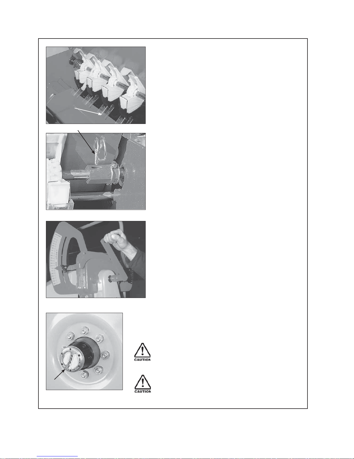
Seed Calibration Procedures
1 Remove the calibration tray from the brackets on
the seedbox. Place the tray (or trays) on the support
members below the seeders.
2 Position all the clear plastic seed diverters to redirect
the seed into the calibration trays as in Fig 15/1.
3 Make sure all the shutters are open and set to the
position indicated in the seed charts for your particular
seed. Refer P16, Fig 9,10 & P17, Fig 13.
4 Agitator Shaft - Check the seed chart for hints on
whether to connect or disconnect this shaft during
seeding. Refer P16, Fig 9, 10 & Fig 16/1.
5 For the test, half fill the box with seed. If this is not
possible make sure the seed is evenly distributed within
the box.
6 Now the 3 basic settings must be made using the figures
from the Sowing Charts P 16, Fig 9, 10. For setting method
refer...
P 17.
Gearbox Setting Lever.
P 17.
Selecting the Gear Ratio.
P 17. Setting Seeder Shutter Slides.
P 17. Bottom Flap settings.
Note For seeds which are not covered in the Sowing
Chart, use the figures for a seed of comparable size and
shape.
7 Place the crank handle over the hexagonal drive dog on
the gearbox input shaft and turn clockwise until the seed
flows consistently from the seeders. To ensure complete
filling of the seed unit continue turning the crank until
the calibration tray is approximately half full then empty
into the seedbox. The drill is now ready for calibration.
Refer Fig 17.
8 Turn the crank handle the required number of
revolutions as in the table fig 19 on P 19.
Note The Calibration is usually done for 1/40th hectare.
For very small seed rates or when using inaccurate
scales (i.e. unable to measure to the nearest gram) the
calculation based on 1/10th hectare should be used.
Important - Before commencing sowing check that the
freewheeling hub positioned at the gearbox end of the
drill is set to 4 x 4, not 4 x 2 which is only for transport.
Refer Fig 18/1.
Scales must be accurate to 2 grams as any error
can be multiplied by up to 40 giving inaccurate
calibration results.
fig 15
fig 16
fig 17
fig 18
1
1
1
Page 21
19
Pt. No. 67304
Issue 1217
Machine Row Sowing Size Spacing
Width (m)
15 Run
150 2.25 49 197 Hign
17 Run 130 2.21 50 200.5
Speed
15 Run 150 2.25 30.5 122.5
Low
17 Run 130 2.21 31 125
Speed
19 Run 150 2.85 39 155.5
High
21 Run 135 2.84 39 156
Speed
19 Run 150 2.85 24 97
Low
21 Run 135 2.84 24.5 97
Speed
23 Run 150 3.45 32 128.5
High
26 Run 130 3.38 32 129
Speed
23 Run 150 3.45 20 80
Low
26 Run 130 3.38 20 80
Speed
Number of Hand Crank Turns for Seed Rate Calibration
9 Weigh the seed collected during the test in kilograms.
10 Calculate the seed rate by multiplying the kgs previously
collected x 40 (1/40th ha method) or x 10 (1/10th ha
method) depending on requirement. If the resultant
calculation does not produce the desired seed rate use
the enclosed seed rate calculator disc to determine the
correct gearbox setting.
Refer Use of Seed Rate Calculator P 20.
Suggestion To be on the safe side and until confidence
has been gained with the method of calibration it is advisable to
conduct a second test at the newly determined gearbox setting.
11 Where a coated seed is used it is advisable to check the
calibration after 1 hectare as dressings can tend to create a
coating on the seed metering wheels thus changing the the
flowing properties of the seed which in turn alters the seed
rate.
Calculating Number of Hand Crank Turns for
Other Working Widths
1 For clutch output sprocket of 19 tooth and gearbox input
sprocket of 15 tooth (standard High Speed Setting)...
Constant = 0.443
2 For clutch output sprocket of 15 tooth and gearbox input
sprocket of 19 tooth.(Low Speed Setting)...
Constant = 0.276
Crank Turns =
Area in Metre
2
x Constant
Working Width
For 1/40 Hectare (250 m2) Calibration
Seed Rate = Actual Seed Collected (kg) x 40
For 1/10 Hectare (1000 m2) Calibration
Seed Rate = Actual Seed Collected (kg) x 10
Speed Setting
Gearbox Clutch
Sprocket Sprocket
High Speed
15 Tooth 19 Tooth
(Standard)
Low Speed 19 Tooth 15 Tooth
Turns for
1
/
40
Hectare
Turns for
1
/
10
Hectare
Speed Setting
(Refer Above)
fig 19
Page 22
20
fig 20
Recalculating the Constant
It is especially important in arable situations to
check the rolling circumference of the tyre when
in the cultivated area to be sown, and if necessary,
recalculate the constant and hence the number of crank
turns.
If there is a significant difference at that time from the figure
used for calculations in this manual (Fig 20), the constant
should be recalculated and hence the crank turns for those
particular conditions.
Note - If a significant difference is found in the rolling
circumference the H1 setting should be adjusted on the
hectaremeter. Refer P 24.
1 To recalculate the constant due to altered conditions or
specific requirements use the formulae in Fig 20.
2
To obtain the rolling circumference of the tyre 1/2 fill the
seed/fertiliser boxes or simulate
this loading.
Mark the tyre of the drill at 900 to the
ground and the point of contact with
a mark on the ground. Move the drill
forward 3 revolutions until the mark
on the tyre is again at 90
0
to the
ground. Measure the distance along
the ground and divide by 3 to give
the rolling circumference of the tyre.
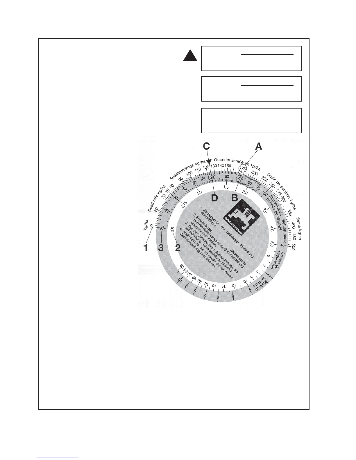
Use of Seed Rate
Calculator
Determining the gear box
scale setting using the
calculator.
Usually the first calibration test yields
a different seed rate. However with
the value determined from the first
test it is possible to determine the
correct gearbox setting with the aid
of the enclosed disc calculator, Fig
21. The disc calculator consists of
3 scales. An outer white scale (Fig
High Speed
=
1.667
Constant
Rolling Circumference
of Tyre
Low Speed
=
1.038
Constant
Rolling Circumference
of Tyre
Rolling Circumference
used for calibration was... 3.76metres
(10 ply tyre)
Setting Example (Desired seed Rate 125kg/ha)
1 From the calibration procedure (described on P 17-19) at a gearbox lever
setting of “70” a seed rate of 175 kg/ha was obtained.
2 Turn the inner disc until the measured seed rate of 175kg/ha (Fig 21/A) is in
line with the related actual gearbox setting of “70”.(Fig 21/B)
3 Read off from the disc rule the necessary gearbox setting for the required
seed rate of 125kg/ha (Fig 21/C) In this example the correct setting is “50”
(Fig 21/D)
4 To be on the safe side the new gearbox setting can be checked by another
calibration test.
!
Page 23

21
Pt. No. 67304
Issue 1217
Calibration Deviations
Deviations Between the Calibration Test and the Actual
Seed Rate
The most frequent cause for changes between the calibration test and
the seed rate lies in the flowing properties of seed during sowing. These
changes in properties generally result from reactions of the dressing
agents to temperature, humidity or abrasion. These changes will become
even more obvious when the bottom flaps are incorrectly set. If the setting
of these flaps leaves too large a gap an uncontrollable additional flow
of seed can occur during seeding; especially when assisted by the drill
bouncing, a condition not simulated while conducting the calibration tests.
For this reason the basic setting of the bottom flaps should be checked at
regular intervals. For more details refer P 30, Fig 39.
Residues from the seed dressing on the bottom flaps and metering wheels
can also influence the flowing properties of the seed and thus the seed
rate. In such cases a balance will occur only after a period of time and it is
recommended to repeat the calibration test to confirm the seed rate after
2-3 seedbox fillings, nominally when the seed box is half empty.
Only then will a balance occur and the seed rate will stabilise.
Wheel Slip Deviations
It is always possible with rubber tyred drills in extreme ground conditions
to get wheel slip. Not normally a problem with cleated type tyres in good
condition, but more so in the arable situation with the less agressive
tread patterns normally found on this type of machine. The result; large
differences between the calibration test and the actual sowing rate,
obviously less seed deposited than required. The number of crank turns
indicated in the table on P19 is correct in most circumstances other
than those mentioned above; however soft seed beds and a fully laden
machine can affect the rolling circumference of the tyre.
Should you require to check this due to some unforeseen circumstances
proceed as follows...
Measure an area of 250 m
2
(1/40 Hectare) - this corresponds to a machine
travel of... Refer Fig 22.
For this calibration test place the crank handle over the hexagonal drive
dog on the gearbox input shaft. Now move the machine slowly forward
over the measured distance, counting the number of turns of the crank
handle as you go. Using this number of crank turns repeat the calibration.
Machine Row Sowing Travel
Size Spacing Width (m) Distance
15 Run 150 2.25
111m
17 Run 130 2.21 113m
19 Run 150 2.85 87.5m
21 Run 133 2.84 88m
23 Run 150 3.45 72.5m
26 Run 130 3.38 72.5m
fig 22
Page 24

22
fig 26
1
Hints for Sowing with Variable Speed Gearbox
This gearbox allows for stepless changes in the speed of the
metering shaft and thus the seed rates. Due to the variations
in seed type and application rates there are 2 speed ranges
available.
By changing from High Speed to Low Speed the range of
settings and control is dramatically increased. The machines
are supplied ex the factory set to the high speed configuration.
Change to the Low Speed when the gearbox setting is down to
10 on the scale and the desired seed rate cannot be obtained.
To change the speed setting from high to low, remove the wing
nut and chain cover.
Release the tension on the chain (fig 23,1) by forcing back
the chain tensioner (fig 23,2) and hold in place with the crank
handle. Remove the chain from the 19 tooth output sprocket to
the 15 tooth sprocket, then remove the chain from the 15 tooth
gearbox sprocket to the 19 tooth. Check the chain is correctly
aligned then release the chain tensioner. Ensure the tension
roller is correctly aligned with the chain. Replace guard and
calibrate as required. Low speed set-up shown in fig 24.
To Determine the Gearbox Setting after a Speed
Change
For determining the correct gearbox setting after the speed
change, conduct the first test at 50. With the weight of seed
collected find your correct setting with the aid of the disc
calculator refer P 20, Fig 21.
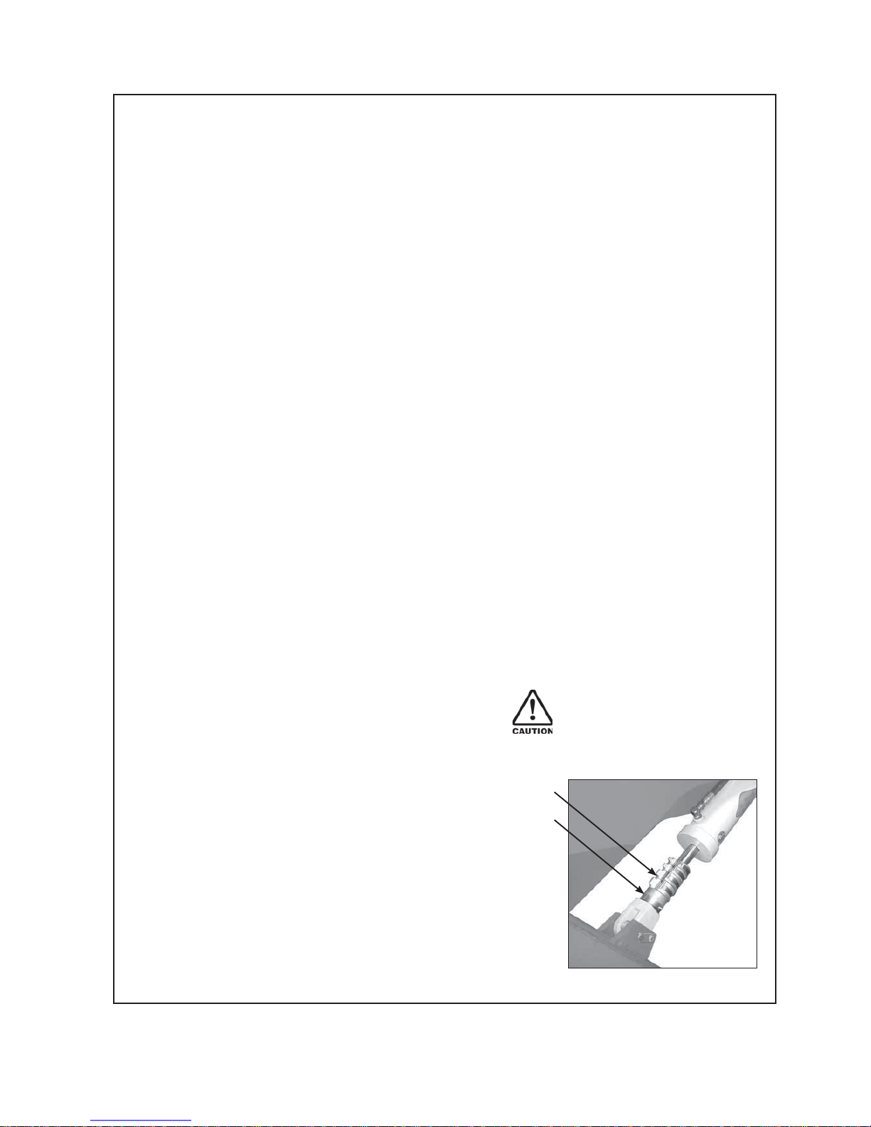
Sowing of Fine Seeds
For sowing fine seeds the Enviro Drill is equipped as standard
with a combined normal and fine seed
“Elite” metering wheel
(Fig 25/1).
During grain sowing and other larger varieties of seed both the
normal and fine seed metering wheels are coupled and both
rotate. In order to convert the seed drill to sow fine seed insert
the crank handle to rotate clockwise until the holes
(Fig 25/2) of
the fine seed wheel are visible. Using the tool supplied (Fig
26/1) disengage the the pin inside the hole so that the normal
metering wheel rotates freely on the metering shaft.
At this time it would be advisable to close any shutter slides
not required for the fine seed sowing.
When seed is to be sown again using the normal metering wheel
press the pin, from the normal metering
wheel side (opposite direction to before),
using the tool, back into the hole of the fine
seed wheel thus reconnecting the drive
between the two.
High Speed
Low Speed
1
2
15T
19T
15T
19T
1
3
fig 23
fig 24
fig 25
2
1
Page 25

23
Pt. No. 67304
Issue 1217
fig 27
1
Caution - When resetting the metering wheels
on the seeder shaft
Care should be taken when tightening the grub screws
(Fig 25/3)
on the fine seed wheel. Adjust the grubscrew until
the movement of the metering wheel just stops, then tighten
no more than 1/8 of a turn.
Do not overtighten as this can result in breakages while
operating and may render the warranty on these units void.
fig 28
fig 29
Small Seed
Calibration with Disconnected Agitator Shaft
The fine seed metering wheel used in Clough Drills is
especially well suited for sowing small seeds such as rape.
Due to the intensive action caused by the agitator the seeds
can adhere to each other, or be damaged, causing irregular
sowing/germination.
Therefore it is recommended that
when sowing small seeds, especially oil seeds and thin
shelled seeds, the drive to the agitator is disconnected.
To do this remove the lynch pin as shown in Fig 27/1.
Deviations between the calibrated and actual seed rate can
occur when residual dressing agent sticks to the bottom flaps
and thus slows the flow of seed. Before beginning the actual
calibration test fill the calibration trays by turning the crank
handle at a high speed around the 90 setting on the gearbox
scale. This will cause an immediate buildup of the dresssing
agent on the flaps. Return the contents of the calibration
trays to the seed box and proceed with the actual calibration.
Due to the residue buildup on the flaps your calibration will
now reflect accurately the required seed rate.
It is advisable with small seeds to use the 1/10 hectare
method for your calibration, thus cutting down on weighing
errors.
Note - Remember to reconnect the agitator shaft as required
for other seeds otherwise the consistency of seed rate will be
affected.
Sowing Peas
Peas having the size and shape as illustrated in Fig 28 (e.g.
White Field Peas), can be sown without problems with all
Clough Drills with this type of metering wheel.
The flap should be set to a gap of at least “3” on the flap
setting lever. Refer Page 17, Fig 14.
With these peas it should not be necessary to run the agitator
shaft.
Peas having the size and shape as illustrated in Fig 29 (e.g.
Green or Garden Peas), tend to bridge inside the seedbox
and do not flow freely.
This multi-faceted pea requires agitation for sowing.
Page 26

24
‘Enviro’ Seed Drill Calibration Notes
Page 27

25
Pt. No. 67304
Issue 1217
Farmscan Jackal v3 Settings Setup
Refer to the manual supplied with your Farmscan Jackal kit for information and operation.
Farmscan Jackal v3 Factory Setup for Enviro 740
Refer to pages 6,9,11 of the Farmscan Jackal v3 manual.
Input 2 -Two wire ‘reed’ sensor for ‘Area/Speed Wheel’
measurement taken from shaft on drive pedestal.
The white ‘signal’ lead is connected to input A2.
Refer to the Farmscan manual if you want to make additional sensor connections.
It is advisable, as with all things electronic, to have a backup of your totals. We suggest you record
these on a daily basis in a notebook or diary.
Input 2 Edit
m/pulse
Auto Set:
Target:0.000m
Meas.pulses: 0
Manual Ratio:
2.817000
NEXT EDIT
Other Settings
Implement Width:
x.xxx m
Extern.Run/Hold:
Disabled
Alarm Beep:2
NEXT EDIT
A1 A2 A3 A4 A5 A6 A7 A8 A9 A10 A11
1 Gnd
A2 Signal
Connect to Pedestal Shaft
2 Wire Sensor via extension
cable.
Connect directly
to Tractor Battery
+12v
0v
red
black
white
black
Machine
Size
Row Spacing
(mm)
Sowing Width
(m)
15 Run 150 2.25
17 Run 130 2.21
19 Run 150 2.85
21 Run 135 2.84
23 Run 150 3.45
26 Run 130 3.38
Rolling Circumference of 12 ply Tyre = 3.708m
See page 20 for directions on how to obtain
an accurate measurement for the tyre fitted
to your machine.
The ‘drive ratio’ is always 1.316
Manual Ratio =
Circumference of Tyre
Drive Ratio
=
3.708 m
1.316
= 2.817m
Page 28

26
Maintenance & Care
General Safety and Accident Prevention Advice
1 Make sure that if the tractor remains attached to the drill
that the ignition key is removed.
2 During maintenance the drill should be supported in such
a manner that if hydraulic failure was to occur the machine
would still be adequately supported.
3 Wear gloves when handling components with cutting
edges such as worn discs etc...
4 Disconnect the electrical supply from the tractor before
doing any electrical maintenance.
5 Refer to safety sections for more safety information.
General Cautionary Maintenance Advice
1 Electric Welding - With the electronic equipment in
modern tractors it is advisable to completely disconnect the
implement from the tractor, or at the very least disconnect
the alternator before attempting any welding.
2 Hydraulics - Ensure hydraulic couplings (male & female)
are clean before connecting. Dirty couplings will result
in hydraulic oil contamination and hydraulic cylinder seal
damage and bore scores. This in turn will result in oil
leakage past the piston seals.
No filter is fitted to the hydraulic system. If hydraulic
fittings and oil supply are not going to be kept clean it is
recommended that a filter be fitted to prevent hydraulic
cylinder damage.
3 Water Blasting - Water blasting, steam cleaning or other
pressurised cleaning processes can force dirt etc. into
undesirable places that may cause damage or rapid part
wear to items such as bearings, seals, chains, bushes etc.
Caution must be exercised.
4 Box set lifting eye profile - these profiles are are provided
for easy removal of the dual boxes from the side frames.
Do not use when boxes are loaded nor to lift machine.
Page 29

27
Pt. No. 67304
Issue 1217
Maintenance
Your new Duncan ‘Enviro’ Drill will give long and efficient
service if given normal care and maintained properly.
1
1
2
3
3
4 9
10
4
4
5
6
6
8
7
fig 32
Item Components Lubricant *Frequency
1 Wheel Bearings Castrol LMX Grease Annually
2 Gearbox Castrol Hyspin AWH 32/68 Oil (1.25 Litres) Maintain Level
3 Wheel Arm Pivots S.K.F. LGEM2 Grease or Equivalent Weekly
4 Drive Chains Suitable Roller Chain Lubricant 6 Monthly
5 Coulter Pivot Pins S.K.F. LGEM2 Grease or Equivalent Weekly
6 Front Disc Bearings (Pre-packed & Sealed) Not Required
7 Double Disc Bearings (Pre-packed & Sealed) Not Required
8 Drive Shafts (Side Frame) (Pre-packed & Sealed) Not Required
9 Agitator Shaft Nylon Bushes Not Required
10 Seeder Shafts Nylon Supports Not Required
* The lubrication frequencies are only a guide. Actual frequency will be dependent on extent of use and ground conditions.
Components Daily Weekly Pre Season
(or after 20Ha) (or after 100Ha) (or 1000 Ha)
Coulters & Double Discs • • •
Press Wheels • • •
Seeders/Agitators/Bottom Flaps • • •
Wheel Nuts • •
Pivot Pin Fasteners • •
Coupling & Safety Chains • •
Roller Chains • •
Gearbox/Clutch • •
Hydraulics (Oil Leaks) • •
Tyre Pressures (25psi / 1.8bar) • •
Bolted Connections •
Precautions with Grease
Greases should not be mixed as the structure may be
weakened by the mixing of different types of thickener
which may cause softening and loss of grease from
bearings by running out.
Lubrication Chart
Maintenance Schedule
Page 30

28
fig 33
fig 35
fig 36
1
1
1
1
2
fig 34
Maintenance Schedule (Refer also to Summary Chart P27)
1 Bolted Connections
All bolted connections on the machine should be checked after
the first 30 hours of operation and retightened if necessary
thereafter at regular intervals. (1000 hectares or annually
whichever occurs first).
2 Gearbox
The oil level in the gearbox can be seen in the oil gauge
window. Changing the gearbox oil is normally not necessary.
For refilling the oil remove the 1/2” BSP plug on the top face
of the gearbox, hydraulic oil Castrol Hyspin AWH 32-68 should
be used. The total filling capacity is 1.25 litres. Refer Fig 33/1.
DO NOT OVERFILL.
3 Clutch
The clutch which is located inside the RH side frame should be
removed, flushed dried and re-assembled annually. Use NO
LUBRICANT such as CRC. For assembly diagram refer P60 in
the parts section of this manual.
4 Roller Chains
All drive chains should first be checked after 20 hours of
operation and thereafter weekly or after 100Ha of operation as
follows:-
The metering wheels of the seed drill are driven via roller chains
from the drive wheel.
The roller chain concealed in the wheel arm has a spring loaded
tensioner, but should still be checked periodically by removing
the cover on the inside face of the wheel arm. This tensioner
must be free to pivot. Refer Fig 34/1.
All other drive chains, apart from the drive from the front gearbox
output shaft to the front seedbox, have spring loaded tensioners,
but should still be checked at regular intervals as previously
mentioned. Refer P 27, Fig 32.
Removing the guard from the outside of the gearbox gives
access to the tensioner on the input drive.
All other tensioners on the output end of the gearbox are
accessed by removing both the fibreglass cover around the
gearbox output sprockets and the rear top cover plate.
To tension the drive chain from the gearbox output shaft to the
front seedbox, loosen the bolts retaining the gearbox to the side
plate and adjust as required.
Cleaning of the roller chains is recommended after long periods
of operation. Remove the chain, wash in kerosene and then
dip them in heated grease or oil or spray them with a suitable
commercial roller chain lubricant.
5 Pivot Bearing Grease Nipples
(Refer Lubrication Chart P27)
Grease at regular intervals (weekly or after 100Ha). There is one
grease nipple per run on the front coulter pivot. (Fig 36/1) and in
the ends of the wheel arm pivot pins (Fig 34/2 & Fig 35/1)
Grease nipples and the grease gun should be carefully cleaned
before use and dirty grease should be fully discharged from the
bushes. Wipe off excess grease and dispose of safely.
Page 31

29
Pt. No. 67304
Issue 1217
fig 37
1
Remove buildup
of dirt behind
the ‘V’ seal.
Clean right into
this corner.
fig 38
Double Disc
Casting
2 1
6 Coulter Bearings
Front coulter bearings are sealed and do not require lubrication.
Check discs for any lateral movement (wobble) on a regular
basis. Replace bearings if there is any noticeable wobble.
7 Double Disc Scrapers
The double disc coulter is equipped with two scrapers to
remove sticking soil. These scrapers have been set by the
factory in such a way so that they lightly touch the discs without
having a noticeable braking effect. After extensive use of the
drill a certain amount of wear may be evident on the scrapers.
The scrapers should be reset using the adjusting bolt so they
just touch the discs as described above.
Refer Fig 37/1.
In some cases if a notch has formed on either of the blades by
the abrasive action of the coulter disc you may need to re-grind
the leading edge to give optimum cleaning action or replace.
8 Double Disc Bearings & Seals
Check that the discs are free from wobble and the bearings run
smoothly. Replace any worn bearings. Check for dirt buildup
behind the rubber ‘V’ seals on the double disc castings. Clean
right into the corner as in Fig 38 and check that the “V” seal
bearing surface is not damaged and is free from rust.
It is recommended to replace the inner “V” seals when the
bearings are replaced.
9 Compensating for Disc Wear
When discs wear in diameter (to 13”) remove the M16 light flat
washer (38/1) so the discs meet. Also remove the nylon washer
(38/2).
10 Rubbing Blocks
Check the plastic rubbing blocks on each side of the front
coulter arms for wear and replace if necessary.
11 Front Disc Pressure Adjustment
Check fasteners regularly on front discs and also on spring
coulters.
12 Depth Control
Grease threaded depth stop.
Check for dirt buildup around the rod seals at the piston head to
ensure seal damage does not occur.
13 Press Wheels
Scrapers will wear.The rate being dependent on the ground
conditions. The minimum clearance is 2mm. In some conditions
a greater clearance may give better performance.
14 Tyre Pressure
The recommmended tyre pressure is 1.8 bar (25psi). Check
tyre pressure regularly to ensure correct pressure is maintained.
Weekly checks are recommended.
Page 32

30
15 Length of Seed/Fertiliser Tubes
These tubes can stretch over a period of time and
require checking at approximately 6 monthly intervals.
Check tubes at the operating depth. Shorten if
necessary to avoid bends which will restrict the flow of
seed/fertiliser.
16 Bottom Flaps
The required seed rate is controlled by both the
metering wheels and the bottom flaps. The seed flows
from the seed box into the metering wheel housings.
Inside the metering wheel housing (Fig 39/1) the seed
is caught between the metering wheel (Fig 39/2) and
the bottom flap (Fig 39/3). The metered amount of seed
is transported by the metering wheel to the edge of the
bottom flap where it drops off into the seed guide tube
which leads to the coulter. Varying grain sizes require
the matching of the flap clearance to the different grain
sizes. This matching is done by raising or lowering
the bottom flaps by using the flap adjusting lever on
the LH end of the seed box. If larger foreign particles,
e.g. stones get between the metering wheel and the
bottom flap, the bottom flap can give way downwards.
A strong return spring (Fig 39/4) brings the bottom flap
immediately back into the working position.
The metering system should be checked every 1/2
year or before any sowing period with an empty
seed box and empty metering housings.
Use the following proceedure:
Put the bottom flap setting levers (located on the LH
end of the seed boxes) in position “1” for the front box
and position “1” for the rear box. Refer Fig 40.
By turning the metering wheel shaft by hand check
the flaps are all set to a gap of 0.1 to 0.5mm (refer
Fig 39).
To adjust individual flaps use the spring tensioning
screw (Fig 39/5)
Note: Re Maintenance Schedule (P27)
Where the frequency is given in terms of time of use
(e.g. weekly) or area covered (e.g.100 Ha) perform the
maintenance task based on whichever occurs first.
Storage
Preparing the Machine for Storage.
Locate a dry level surface. The machine should be stored
wherever possible with the rams retracted. The drive chains
should be lubricated with suitable roller chain lubricant
before prolonged periods of storage.
For longer term storage remove seed/fertiliser tubes from
the coulters and allow to hang without deformation.
fig 40
fig 39
Important !
Page 33

31
Pt. No. 67304
Issue 1217
‘Enviro’ Seed Drill Maintenance Notes
Page 34

32
‘Enviro’ Seed Drill Maintenance Notes
Page 35

33
Pt. No. 67304
Issue 1217
Parts List
‘Enviro’ Seed Drill
Model 740
From Serial Number
Head Office:
P.O. Box 2018
Hilton Highway, Washdyke
Timaru, New Zealand
Telephone (03) 688 2029
Facsimile (03) 688 2821
Australian Branch:
4B Silverton Close
Laverton North 3026
Melbourne, Australia.
Telephone (02) 9314-9666
Facsimile (02) 9314-6810
Page 36

34
7 9
2
22
22
2
1
34
23
5
36
37
38
40
42
41
39
28
3
4
4
5
10 3233
10 33
27 29 35
30
26
6
38
12
1546
45
44
18
2543
45
46
18 44 45 4616
17
21
44
45
46
14 13
132044454611
47
47
24
3531
6 9 8
‘Enviro’ Seed Drill Complete Assembly
Page 37

35
‘Enviro’ Seed Drill Complete Assembly
*N Where N = number of coulters fitted. e.g. 19 for 19 Run Machine (see table below for part number).
Part numbers for different width machines
Item 15 Run 17 Run 19 Run 21 Run 23 Run 26 Run
26 22218 22218 22220 22220 22222 22222
27 22593 22593 22646 22646 22648 22648
28 22586 22586 22636 22636 22638 22638
29 22604 22604 22614 22614 22626 22626
30 22605 22605 22615 22615 22627 22627
31 22388 22389 22392 22393 22396 22400
32 22561 22561 22563(LH) Plus 22571(RH) 22564 22564
33 22915 22915 22917 22917 22919 22919
34 22219 22219 22221 22221 22223 22223
ITEM PART No. DESCRIPTION QTY
1 Refer Page 36/37 Mainframe & Drawbar 1
2 Refer Page 38/39 Wheel Arms 1
3 Refer Page 40/41 Hydraulics 1
4 Refer Page 42/43 Wiring & Lighting Kit 1
5 Refer Page 44/45 Coulter Assembly Complete *N
6 45019 M12 x 30 Class 8.8 Zinc Plated Bolt 24
7 Refer Page 54 Clutch Shaft Assembly 1
8 45140 M16 Nylock Nut 24
9 Refer Page 58/59 Box Drive Shafts 1
10 Refer Page 62/63 Seedbox Assembly 1
11 Refer Page 64 Agitator Drives 1
12 Refer Page 65 Agitator Shaft Assembly 2
13 Refer Page 66/67 Seeder Assembly *N
14 Refer Page 61 Gearbox Final Assembly Pt No 22054 1
15 Refer P 53,56.57 Drive Chains 1
16 Refer Page 60 Clutch Assembly 1
17 22051 Crank Arm & Handle Assembly 1
18 22198 RH Cover Plate 1
19 22199 RH Front Cover Plate 1
20 22200 LH Rear Cover Plate 1
21 22201 LH Front Cover Plate 1
22 17905 12.4/11 x 28 x 10ply Wheel Assembly 2
23 22584 Latch Chain (12 links) 2
24 22743 Plastic Guard (Clutch to Gearbox) 1
25 22527 Fibreglass Guard (Gearbox to Seedboxes) 1
26 Refer Below Frame Rear Beam Assembly 2
27 Refer Below Front Footboard Assembly 1
28 Refer Below Rear Footboard Assembly 1
29 Refer Below Guard Rail Assembly (Short) 1
30 Refer Below Guard Rail Assembly (Long) 1
31 Refer Below Pressure Bar Assembly 1
32 Refer Below Calibration Tray Assembly 1
33 Refer Below Ripstop Weather Skirt 2
34 Refer Below Front Spreader Beam Assembly 1
35 45292 7/16” x 1 1/2” Lynch Pin 2
36 45023S M12 x 50 Class 8.8 Zinc Plated Set Screw 2
37 45131 M12 Class 8.8 Zinc Plated Hex Nut 2
38 45139 M12 Nylock Nut 18
39 45141 M20 Nylock Nut 2
40 45159 M12 Heavy Duty Zinc Plated Flat Washer 20
41 45161 M20 Heavy Duty Zinc Plated Flat Washer 2
42 45063 M20 x 55 Class 8.8 Zinc Plated Bolt 2
43 44991s M8 x 16 Class 8.8 Zinc Plated Set Screw 2
44 44992s M8 x 20 Class 8.8 Zinc Plated Set Screw 10
45 45157 M8 Heavy Duty Zinc Plated Flat Washer 12
46 45165 M8 Zinc Plated Spring Washer 12
47 45341 M10 Zinc Plated Wing Nut 2
Page 38

36
2
252831
1
1121
2211
4
14
12
16
4
14 26 27 31 29
7
24
24
272931272931
15
23
18
41
42
31
45
17
19 203234 3433
3
1213
5
12
38
39
40
10
8
9
35
35
43
44
Part numbers for different width machines
Item 15 Run 17 Run 19 Run 21 Run 23 Run 26 Run
24 22240 22240 22242 22242 22244 22244
25 22256 22256 22258 22258 22260 22260
26 22388 22389 22392 22393 22396 22400
37
36
30
LH Cylinder
Detail
‘Enviro’ Seed Drill Mainframe & Drawbar
Page 39

37
Pt. No. 67304
Issue 1217
‘Enviro’ Seed Drill Mainframe & Drawbar
ITEM PART No. DESCRIPTION QTY
1 22194 LH Endplate Assembly 1
2 22195 RH Endplate Assembly 1
3 22208 Coulter Adjustment Rod Assembly 2
4 22293 Ram Anchor Pin 2
5 22262 Clevis Pin (Wheel Arm, Tabbed) 2
6 22752 LH Wheel Arm Welded Assembly (refer page 36/37) 1
7 22753 RH Wheel Arm Welded Assembly (refer page 36/37) 1
8 43499 Stop Collar Set 1
9 43935 4” x 12” Master Rephasing Ram 1
10 43936 3.75” x 12” Slave Rephasing Ram 1
11 45272 R Clip (S12) or (AG7) 4
12 22270 Clevis Spacer 4
13 45134 M24 Class 8.8 Zinc Plated Hex Nut 4
14 45001s M10 x 20 Class 8.8 Zinc Plated Set Screw 4
15 22310 Draw Bar Clevis Pin 1
16 22318 Draw Bar Axle 1
17 22322 Draw Bar Final Assembly 1
18 22449 Hydraulic Valve Support Assembly 1
19 31478 1 Tonne Jack & Stub Assembly 1
20 31483 Jack Support Bracket Assembly 1
21 43395 Heavy Duty Ratchet Ram/Turnbuckle 1
22 - Turnbuckle Pin (Supplied with turnbuckle) 1
23 4800315 Hose Support 1
24 Refer Below Frame Front Beam Assembly 1
25 Refer Below Carrier Beam Assembly 1
26 Refer Below Pressure Bar Assembly 1
27 45038 M16 x 40 Class 8.8 Zinc Plated Bolt 24
28 45052 M16 x 140 Class 8.8 Zinc Plated Bolt (Carrier Bar Ties) 6
29 45160 M16 Heavy Duty Zinc Plated Flat Washer 12
30 45141 M20 Nylock Nut 5
31 45140 M16 Nylock Nut 22
32 45034 M12 x 130 Class 8.8 Zinc Plated Bolt 1
33 45035 M12 x 140 Class 8.8 Zinc Plated Bolt 1
34 45139 M12 Nylock Nut 2
35 45292 7/16” x 1 1/2” Lynch Pin 2
36 45067 M20 x 75 Class 8.8 Zinc Plated Bolt 2
37 45018S M12 x 25 Class 8.8 Zinc Plated Setscrew 4
38 45418S M10 x 25 Zinc Plated Setscrew 2
39 45158 M10 H/D Zinc Plated Flat Washer 2
40 45166 M10 Zinc Plated Spring Washer 2
41 22305 Swivel Towhitch 1
42 45042 M16 x 60 Class 8.8 Zinc Plated Bolt 4
43 45084 M20 x 240 Class 8.8 Zinc Plated Bolt 1
44 45141 M20 Nylock Nut 1
45 43032 Chains No.3 2
Page 40

38
13
15
35
10
10
46
38
14
45
44
43
LH Wheel
Arm & Axle
RH Wheel
Arm & Axle
Chain Tensioner
Detail
1
2
31 20
20
3
4
4
4
46
38
46
36
48
36
38
36
16
5
5
8
6
7
9
9
30 26
33
33
11 31
1217
28
47 34
34
29
36
18
1832
19
18
25
27
2732
2732
21
40
4141
42
41
42
41
39
22
37 37 42
3737
22
23
22
22
17
Pivot Pin
Detail
35
42
24
46
‘Enviro’ Seed Drill Wheel Arms
Page 41

39
Pt. No. 67304
Issue 1217
‘Enviro’ Seed Drill Wheel Arms
ITEM PART No. DESCRIPTION QTY
1 22753 RH Wheel Arm Welded Assembly 1
2 22752 LH Wheel Arm Welded Assembly 1
3 22271P# Cover Plate 1
4 22282P End Cap 2
5 22292 Wheel Arm Pivot Pin 2
6 22032 6 Square x 22 Long Key 1
7 22295 25T x 1/2” Pitch Primary Sprocket 1
8 22297 19T x 1/2” Pitch Transfer Double Sprocket 1
9 22769 Drive Axle 1
10 22303 2.5mm Nylon Spacer 2
11 22767 Drive Hub 1
12 22768 Plain Wheel Hub 1
13 22465 1/2” x 131 Link BS Chain 1
14 43388 1/2” Pitch Joiner Link 1
15 31285 Chain Tensioner & Shoe Assembly 1
16 30273 Chain Tensioner Nylon Shoe Only (Spares) 2
17 43030 32009 Bearing 2
18 43033 32012 Bearing 3
19 43031 32010 Bearing 1
20 22264 Axle Washer 36mm Bore 2
21 22328P Cover Plate 1
22 43426 Glacier Bush (45mm Bore) 4
23 43427 Glycodur Bush (45mm Bore) 1
24 43644 Freewheel Hub Assembly 1
25 43439 (CC 55 85 08) Oil Seal 1
26 47610 M30 x 1.5 Castle Nut 1
27 43040 (TC 8010010) Oil Seal 3
28 43431 3” Diameter Dust Cap 1
29 22766 M36 x 2 Castle Nut 1
30 45313 M5 x 50 Split Pin 1
31 45317 6.3 x 75 Split Pin 2
32 22765 Bearing Spacer 3
33 45040S M16 x 50 Class 8.8 Zinc Plated Set Screw 16
34 45148 M16 Wheel Nut 16
35 45168 M16 Zinc Plated Spring Washer 16
36 45001s M10 x 20 Class 8.8 Zinc Plated Set Screw 6
37 45018s M12 x 25 Class 4.6 Zinc Plated Set Screw 4
38 45166 M10 Zinc Plated Spring Washer 6
39 45131 M12 Class 8.8 Zinc Plated Hex Nut 1
40 45139 M12 Nyloc Nut 1
41 43118 M8 x 1.25 Pitch Straight Grease Nipple 4
42 22285 Nylon Spacer Washer 4
43 44951s M6 x 16 Class 4.6 Zinc Plated Set Screw 3
44 45164 M6 Zinc Plated Spring Washer 3
45 45150 M6 Light Flat Washer 3
46 45158 M10 Heavy Duty Zinc Plated Flat Washer 6
47 47611 M36 x 4 Castle Nut 1
Page 42

40
1
2
3
5
13
13
13
13
16
16
17
18
17 18
6
7
8
99
Seal kit for item 1 = part No 43414
Seal kit for item 2 = part No 43413
‘Enviro’ Seed Drill Hydraulics
Page 43

41
‘Enviro’ Seed Drill Hydraulics
34
5
14
15
7
10 11
ITEM PART No. DESCRIPTION QTY
1 43935 4” x 12” Master Rephasing Ram 1
2 43936 3.75” x 12” Slave Rephasing Ram 1
3 43393 Stainless Steel Ball Valve 3/8” BSP 1
4 22449 Hydraulic Valve Support Assembly 1
5 22447 Hydraulic Hose 1.70m 1
6 Refer Below Hydraulic hose 1
7 Refer Below Hydraulic hose 1
8 Refer Below Hydraulic hose 1
9 43147 1/2” BSP Male Quick Release Coupling 2
10 43445 1/2” BSPP to 3/8” BSPP Nipple 1
11 43399 3/8” BSPP Male/Female Swivel 1
12 43617 Male Probe Dust Cover 2
13 43496 3/4” UN’O’ to 3/8” BSPT Elbow 4
14 45035 M12 x140 Class 8.8 Zinc Plated Bolt 1
15 45139 M12 Nylock Nut 1
16 43434 Hydraulic Hose Clamp 6
17 45412S M8 x 25 Class 4.6 Zinc Plated Set Screw 6
18 45137 M8 Nylock Nut 6
ITEM PART No. HOSE LENGTH
15 Run 17 Run 19 Run 21 Run 23 Run 26 Run
6 22454 3.15m 3.15m - - - -
“ 22460 - - 3.75m 3.75m - “ 22482 - - - - 4.35m 4.35m
7 22453 4.20m 4.20m - - - -
“ 22459 - - 4.50m 4.50m - “ 22481 - - - - 4.80m 4.80m
8 22455 6.20m 6.20m - - - -
“ 22461 - - 6.50m 6.50m - “ 22483 - - - - 6.80m 6.80m
Page 44

42
5
6
‘Enviro’ Seed Drill Wiring & Lighting Kit
Page 45

43
Pt. No. 67304
Issue 1217
‘Enviro’ Seed Drill Wiring & Lighting Kit
LH Side
RH Side
1 898
3
4
12 11
13 10
13
14
15
15
14
10
11 12
6 6
3
4
2
7
7
10
15
1616 16 10 1615
ITEM PART No. DESCRIPTION QTY
1 22346 LH Lamp Bracket Assembly 1
2 22347 RH Lamp Bracket Assembly 1
3 43435 Combination Rear Lamp 2
4 43436 Marker Lamp 2
5 43437 Trailer Round Connector Plug 1
6 43438 5 Core Trailer Flex (15 to 21 Run x 12m, 23/25 Run x 13m) 1
7 43443 White 1mm Appliance Wire x 1m 1
8 43444 Brown 1mm Appliance Wire x 1m 1
9 43448 No. 6 Rubber Grommet 1
10 45122 M6 Class 8.8 Zinc Plated Hex Nut 1
11 45137 M8 Nylock Nut 4
12 44962 M8 x 30 Class 8.8 Zinc Plated Bolt 4
13 44951s M6 x 16 Class 8.8 Zinc Plated Set Screw 4
14 45860 No. 12 x 3/4” Pan PZ Zinc Plated Self Tapping Screw 4
15 - 5W Festoon Bulb 15 x 44mm 4
16 - 21W Festoon Bulb 15 x 44mm 4
Page 46

44
‘Enviro’ Seed Drill Coulter Assembly
ITEM PART No. DESCRIPTION QUANTITIES
15R 17R 19R 21R 23R 26R
1 Refer P 46/47 Front Disc & Springs Assembly 15 17 19 21 23 26
2 Refer P 48/49 Double Disc Assembly 15 17 19 21 23 26
3 Refer P 50/51 Press Wheel Assembly 15 17 19 21 23 26
4 Refer P 52 Optional Press Wheels As Required
5 22057 LH Mounting Bracket 7 8 9 10 11 13
6 22058 RH Mounting Bracket 7 8 9 10 11 12
7 22060 Rubbing Block 150 mm Spacing 14 - 18 - 22 8 22067 Rubbing Block 135 mm Spacing - - - 20 - -
9 22068 Rubbing Block 130 mm Spacing - 16 - - - 25
10 45031 M12 x 100 Class 8.8 Z/P Bolt 444444
11 45032 M12 x 110 Class 8.8 Z/P Bolt 12 14 16 18 20 24
12 45139 M12 Nyloc Nut 16 18 20 22 24 28
13 45910 M6 x 25 Pan Hd Posidrive Screw 28 32 36 40 44 50
See Page 48 See Page 52
See Page 48
See Page 45
See Page 46
Page 47

45
Pt. No. 67304
Issue 1217
‘Enviro’ Seed Drill Front Disc Assembly
5
58
8
10
7
7 9
4
3
4
3
6
ITEM PART No. DESCRIPTION QTY
1 22000 406 x 4 Plain Disc 6 Hole 1
2 22001 406 x 4 Fluted Disc 6 Hole 1
3 11351 Bearing 6305-2RS1 2
4 17537 6 Hole Single Bearing Housing 2
5 22078 Seal Collar 2
6 22102 Bearing Spacer 1
7 22080 25mm Bore Dust Cap 2
8 43352 Vee Ring Seal V-40A 2
9 45002s M10 x 25 Class 8.8 Zinc Plated Set Screw 6
10 45138 M10 Nylock Nut 6
11 22003 Action 2000 Fluted Disc 406 x 4 (6 Hole) 1
11
Note: Item 8 Vee Ring Seal
Orientation
Page 48

46
‘Enviro’ Seed Drill Front Coulter Assembly
18
2
3
5
6
1
7
9
10 11
9 7
11 10
24 12
13
15
16
17
4
14
25
8
21
19 20
23
22
Page 49

47
Pt. No. 67304
Issue 1217
ITEM PART No. DESCRIPTION QTY
1 Refer Page 45 Front Disc Assembly 1
2 22116 Front Coulter Spring Sleeve 1
3 61005 RH Front Coulter Arm Assembly 1
4 45143 M24 Nyloc Nut 1
5 45169 M20 Spring Washer Z/P 1
6 45120 M20 Half Nut Grade 8.8 Z/P 1
7 61013 Thrust Washer 30 Bore 2
8 61006 LH Dragbar Assembly 1
9 43510 Glacier Bush 30mm Bore 2
10 61014 Thrust Washer 50 Bore 2
11 43515 Glacier Bush 50mm Bore 2
12 45139 M12 Nyloc Nut 2
13 22115 Front Coulter Tension Spring 1
14 22117 Front Coulter Spring Anchor 1
15 45040s M16 x 50 Set Screw Grade 8.8 Z/P 1
16 44944 M20 x 150 Bolt Grade 10.9 Z/P 1
17 22099 Coulter Spring Support 1
18 61012 Coulter Arm Support 1
19 45071 M20 x 110 Bolt Grade 8.8 Z/P 1
20 61001 LH Front Coulter Arm Assembly 1
21 22101 Coulter Axle Bolt 1
22 45160 M16 H/D Flat Washer Z/P 1
23 45038s M16 x 40 Set Screw Grade 8.8 Z/P 1
24 61010 RH Dragbar Assembly 1
25 45030 M12 x 90 Bolt Grade 8.8 2
26 43118 Grease nipple M8 Straight 1
‘Enviro’ Seed Drill Front Coulter Assembly
Page 50

48
‘Enviro’ Seed Drill Double Disc Assembly
8
10
3
7
6
5
4 3 2 1
5
6
7
3
10
9
2 3
4
17
16
15
14 13 12 11
18
19
20
21
22
23
25
26
27
28
24
Page 51

49
Pt. No. 67304
Issue 1217
‘Enviro’ Seed Drill Double Disc Assembly
ITEM PART No. DESCRIPTION QTY
1 22203 Double Disc Casting Welded Assy (Mk2) 1
2 22136 Plastic Spacer 2
3 43352 Vee Ring Seal V-40A 2
4 45154 M16 Light Flat Washer Z/P 2
5 Refer Page 50 Disc Sub Assembly 2
6 22079 Bearing Sleeve 2
7 22078 Seal Collar 2
8 45040 M16 x 50 Bolt Grade 8.8 Z/P 1
9 22082 Disc Retaining Bolt (Left Hand Thread) 1
10 22077 Dust Cap 16mm Bore 2
11 22114 Spring Rod Assy 1
12 22109 Bottom Spring Retainer 1
13 17753 Inner Spring 1
14 17752 Outer Spring 1
15 17750 Top Spring Cap 1
16 22110 Spring Rod Cap 1
17 45141 M20 Nyloc Nut 1
18 22069 D/Disc Scraper Mounting Strap 1
19 45152 M10 Light Flat Washer Z/P 1
20 45166 M10 Spring Washer Z/P 1
21 45001s M10 x 20 Set Screw Grade 8.8 Z/P 1
22 45136 M6 Nyloc Nut 1
23 22086C R/H Scraper Casting 1
24 22087C L/H Scraper Casting 1
25 22088 Scraper Hinge Stainless 1
26 22070 Double Disc Scraper Tensioner 1
27 45156 M6 HD Flat Washer Z/P 1
28 44955 M6 x 30 Bolt Grade 8.8 Z/P 1
29 45139 M12 Nyloc Nut 1
30 45023 M12 x 50 Bolt Grade 8.8 Z/P 1
Page 52

50
Page 53

51
Pt. No. 67304
Issue 1217
‘Enviro’ Seed Drill Disc Assembly
ITEM PART No. DESCRIPTION QTY
1 45001s M10 x 20 Set Screw Grade 8.8 Z/P 6
2 22002 380 x 4mm Plain Disc x 6 Hole 1
3 22081 Seal Face Ring 1
4 11351 Bearing 6305 1
5 17537 Bearing Housing 6 hole 1
6 45138 M10 Nyloc Nut 6
7 22079 Bearing Sleeve 1
8 22078 Seal Collar 1
9 43352 Vee Ring Seal V-40A 1
10 22077 Dust Cap (16mm Bore) 1
1 2 3 4
7 8 9
10
5 6
Note: Item 9 Vee Ring Seal
Orientation
SEE NOTE
Page 54

52
‘Enviro’ Seed Drill Press Wheel Assembly
1 2 3 4
7
5
6
8 9
10 11
12
13
14
15
16
13
17
18
19
17
20
4
21
24
25 26
27 28 26 25
24
29 2213
23
Page 55

53
Pt. No. 67304
Issue 1217
‘Enviro’ Seed Drill Press Wheel Assembly
ITEM PART No. DESCRIPTION QTY
1 23536 Tension Spring 7.5kN/m 1
2 24451 Upper Jaw Assy RH 1
3 45321 D Shackle 5/16” 1
4 45139 M12 Nyloc Nut 5
5 23510 Jaw Lock Pin Assembly 1
6 23506 Spring Slide 1
7 23525 Tension Spring 1
8 23504 Upper Jaw Spacer 1
9 45158 M10 Heavy Duty Flat Washer Z/P 2
10 45166 M10 Spring Washer Z/P 2
11 45001s M10 x 20 Grade 8.8 Z/P S/Screw 2
12 29267 Scraper for 15” x 80mm Wedge Press Wheel 1
13 45025 M12 x 60 Grade 8.8 Z/P Bolt 5
14 23515 Lower Jaw Assembly 1
15 24450 Upper Jaw Assy LH 1
16 24452 Jaw Pivot Pin 1
17 24456 Bush Top Hat 25x30x32 2
18 23503 Spring Retainer 1
19 45187 M10 x 16 Socket Head Grubscrew 1
20 45051 M16 x 130 Grade 8.8 Bolt 1
21 23551 RH Press Wheel Arm 2
22 45119 M16 Grade 8.8 Hex Half-Nut 1
23 45168 M16 Spring Washer Z/P 1
24 10283 Oil Seal 2
25 61022 Bearing Mount 2
26 11351 Bearing 6305 2
27 43573 Press Wheel Solid Vee Wedge 1
28 61021 Spacer 1
29 23550 LH Press Wheel Arm 1
Page 56

54
Page 57

55
Pt. No. 67304
Issue 1217
‘Enviro’ Seed Drill Drive Chains
1 8
1719 1719
9
10
7
2
11
1219
7
3
7
4 7
5
13 18
1419
14 19 15 16
7
6 7
ITEM PART No. DESCRIPTION QTY
1 22465 1/2” x 131 Link BS Chain (Wheel Hub to Arm Pivot Pin) 1
2 22466 1/2” x 55 Link BS Chain (Arm Pivot Pin to Clutch) 1
3 22467 1/2” x 79 Link BS Chain (Clutch to Gearbox Input) 1
4 22468 1/2” x 119 Link BS Chain (Gearbox to Front Seed Box) 1
5 22469 1/2” x 95 Link BS Chain (Gearbox to Rear Box Idler) 1
6 22470 1/2” x 103 Link BS Chain (Rear Box Idler to Rear Seed Box) 1
7 43388 1/2” Pitch Joiner Link 6
8 22295 25T x 1/2” Pitch Primary Sprocket (Hub Shaft) 1
9 22297 19T x 1/2” Pitch Transfer Double Sprocket (Arm Pivot Pin) 1
10 43427 Glycodur Bush (45mm Bore) 1
11 22161 Clutch Final Assembly Refer Page 28 1
12 22157 19 Tooth 1/2” Pitch 25mm Bore Sprocket (Clutch Output Shaft) 1
13 22043 15 Tooth 1/2” Pitch 25mm Bore Sprocket (Gearbox Input Shaft) 1
14 22044 15 Tooth 1/2” Pitch 20mm Bore Sprocket (Gearbox Output) 2
15 22521 25T x 1/2” Pitch Transfer Double Sprocket 1
16 43364 Glacier DU Bush (MB-2030-DU) 1
17 22537 25 Tooth 1/2” Pitch 20mm Bore Sprocket (Box Shafts) 2
18 22023 6 x 6 x 85 Long Key (Gearbox Input Drive Adapter) 1
19 22538 6 x 6 x 25 Long Key (Drive Sprockets) 6
Page 58

56
3
18
16
15
12
10
11
221
1
2
25
25
21
21
23
23
6
27
13
24
35
32
4
5
29
17
24
16
20
9
7
28
8
22
19
14
17
3026
34
10 Diameter Pin
Welded in Frame
‘Enviro’ Seed Drill Clutch Shaft Assembly
31
Jackal v3 kit
Page 59

57
Pt. No. 67304
Issue 1217
‘Enviro’ Seed Drill Clutch Shaft Assembly
ITEM PART No. DESCRIPTION QTY
1 43386 “Y” Bearing YET205 (25mm) 2
2 30359 Pressed Steel 3 Bolt Bearing Housing PF52 (2 Flanges) 2
3 22158 Clutch Actuating Arm Assembly 1
4 22144 Clutch Shaft (25mm) Quick Change 1
5 22159 Clutch Arm Return Spring 1
6 22165 Clutch Chain Assembly 1
7 22480 Chain T ensioner Arm Assembly 1
8 22522 Tensioner Torsion Spring LH 1
9 22535 Chain Tension Nylon Roller 1
10 45370 M16 Starlock Fixing Washer 1
11 45276 6mm Roll Pin x 60 long 1
12 45030 M12 x 90 Class 8.8 Zinc Plated Bolt 1
13 45122 M6 Class 8.8 Zinc Plated Hex Nut 3
14 45130 M10 Class 8.8 Zinc Plated Hex Nut 1
15 45131 M12 Class 8.8 Zinc Plated Hex Nut 1
16 45136 M6 Nylock Nut 9
17 45138 M10 Nylock Nut 4
18 45139 M12 Nylock Nut 1
19 45140 M16 Nylock Nut 1
20 45150 M6 Zinc Plated Light Flat Washer 1
21 45151 M8 Zinc Plated Light Flat Washer 6
22 22474 Chain Tensioner Spacer (6mm) 1
23 45165 M8 Zinc Plated Spring Washer 6
24 44952s M6 x 20 Class 8.8 Zinc Plated Set Screw 1
25 44991s M8 x 16 Class 8.8 Zinc Plated Set Screw 6
26 45368 M10 Starlock Fixing Washer 1
27 45041 M16 x 55 Class 8.8 Zinc Plated Bolt 2
28 45002s M10 x 25 Class 8.8 Zinc Plated Set Screw 1
29 22162 Hectaremeter Sensor Mounting Bracket 1
30 22161 Clutch Final Assembly Refer P 28 1
31 44571K Jackal v3 Hectaremeter Kit. Contains items 32 - 39 -
32 44572 Jackal v3 Speed & Area Meter 1
33 44573 Owner's Manual Jackal v3 1
34 43403 Hectaremeter Sensor w/o Nuts AA-110P/5 1
35 43404 Hectaremeter Clamp & Magnet AA-117 1
36 43154 Hectaremeter Sensor Brass Nut 2
37 44028 Window Mount AH-407 1
38 44031 7.5m Cable (2 way) AC-088 1
39 44574 Power Cable Assy Jackal v3 (complete: comprises items 39-42 below) 1
40 44029 Power Cable AC-105 1
41 44575 Cable S/Assy Jackal v3 (short 2way) 1
42 44146 11 way Terminal Block P321 Green 1
Page 60

58
10
11
13 14
13
17
18
1
1823
16 29 22
15
26
20
2
3 4
21
12
59
22
241925
6 8
22
7
9
22
9
22
7
Idler Detail
Gearbox to Boxshaft
Drive Detail
Clutch to Gearbox
Drive Detail
‘Enviro’ Seed Drill Box Drive Chain Details
Page 61

59
Pt. No. 67304
Issue 1217
‘Enviro’ Seed Drill Box Drive Chain Details
ITEM PART No. DESCRIPTION QTY
1 22471 1/2” x 81 Link BS Chain (Clutch to Gearbox Input) 1
2 22468 1/2” x 119 Link BS Chain (Gearbox to Front Seed Box) 1
3 22469 1/2” x 95 Link BS Chain (Gearbox to Rear Box Idler) 1
4 22470 1/2” x 103 Link BS Chain (Rear Box Idler to Rear Seed Box) 1
5 25982 15/19 Tooth 1/2” Pitch 25mm Bore Change Sprocket 1
6 25982 15/19 Tooth 1/2” Pitch 25mm Bore Change Sprocket 1
7 22044 15 Tooth 1/2” Pitch 20mm Bore Sprocket (Gearbox Output) 2
8 22023 6 x 6 x 85 Long Key (Gearbox Input Drive Adapter) 1
9 22538 6 x 6 x 25 Long Key (Drive Sprockets) 6
10 43386 “Y” Bearing YET205 (25mm) 2
11 30359 Pressed Steel 3 Bolt Bearing Housing PF52 (2 Flanges) 2
12 22144 Clutch Shaft (25mm) Quick Change 1
13 22480 Chain T ensioner Arm Assembly 2
14 22522 Tensioner Torsion Spring LH 1
15 22523 Tensioner Torsion Spring RH 1
16 22475 Chain Tensioner Spacer (20mm) 1
17 22535 Chain Tension Nylon Roller 2
18 22050 Crank Adaptor 1
19 45130 M10 Class 8.8 Zinc Plated Hex Nut 6
20 45140 M16 Nylock Nut 2
21 45160 M16 Zinc Plated Heavy Duty Flat Washer 1
22 45181 M8 x 12 Socket Head Grubscrew 6
23 45180 M8 x 10 Socket Head Grubscrew 2
24 22197 M10 Retaining Stud 2
25 45166 M10 Zinc Plated Spring Washer 2
26 45045 M16 x 75 Class 8.8 Zinc Plated Bolt 1
Page 62

60
10
16
11
13
11
17
19
12
15
8
20
5
5
7
7
7
7
5
5
6
6
6
7
14
14
14
14
7
7
7
3
18
6
18
18
18
4
4
3
1
2
Rear Box Shaft
Assembly
Rear Box Idler
Assembly
Front Box Shaft
Assembly
‘Enviro’ Seed Drill Box Drive Shafts
Page 63

61
Pt. No. 67304
Issue 1217
‘Enviro’ Seed Drill Box Drive Shafts
ITEM PART No. DESCRIPTION QTY
1 22521 25T x 1/2” Pitch Transfer Double Sprocket 1
2 43364 Glacier DU Bush (MB-2030-DU) 1
3 22537 25 Tooth 1/2” Pitch 20mm Bore Sprocket (Box Shafts) 2
4 22538 6 x 6 x 25 Long Key (Drive Sprockets) 6
5 43385 “Y” Bearing YET204 (20mm) 4
6 44993s M8 x 25 Class 8.8 Zinc Plated Set Screw 8
7 43387 Pressed Steel 2 Bolt Bearing Housing PFT47 (2 Flanges) 4
8 22516 Front Box Drive Shaft (20mm) 1
9 22480 Chain T ensioner Arm Assembly 1
10 22523 Tensioner Torsion Spring RH 1
11 22535 Chain Tension Nylon Roller 1
12 45130 M10 Class 8.8 Zinc Plated Hex Nut 6
13 45041 M16 x 55 Class 8.8 Zinc Plated Bolt 1
14 45137 M8 Nylock Nut 8
15 45138 M10 Nylock Nut 1
16 45140 M16 Nylock Nut 1
17 45160 M16 Zinc Plated Heavy Duty Flat Washer 1
18 45181 M8 x 12 Socket Head Grubscrew 4
19 45007s M10 x 50 Class 8.8 Zinc Plated Set Screw 1
20 22517 Rear Box Drive Shaft (20mm) 1
Page 64

62
1 2
2
3 4
5 6 7
8
9
10
‘Enviro’ Seed Drill Clutch Assembly
ITEM PART No. DESCRIPTION QTY
1 22151 Clutch Output Hub Assembly 1
2 43353 Vee Ring Seal V-65A (Forsheda) 2
3 22149 Clutch Sleeve Assembly 1
4 22152 Clutch Spring (R.H.) 1
5 43357 Glycodur Bush (35mm Bore) 1
6 22145 Clutch Input Hub 1
7 43358 A35 Seeger Tru-Arc Circlip 1
8 22153 19T 1/2” Input Sprocket 1
9 47022 M6 x 20 Socket Head Countersunk Screw 3
10 45280 6mm Roll Pin x 60 long 1
Page 65

63
Pt. No. 67304
Issue 1217
‘Enviro’ Seed Drill Gearbox Final Assembly
1 29
10
8
9 72
3
3
4
7
7
9
5
8
6
69 997
10 1010
1011
11
1110
9
ITEM PART No. DESCRIPTION QTY
1 22053 Gearbox Sub-Assembly 1
2 22036 Speed Adjusting Quadrant 2
3 22038 Speed Adjustment Lever 2
4 22041 Speed Indicator Label Anticlockwise 1
5 22042 Speed Indicator Label Clockwise 1
6 43366 Tri-Knob with M8 Tapped Centre 2
7 45157 M8 Heavy Duty Zinc Plated Flat Washer 4
8 47031 M8 x 40 Cup Head Class 4.6 Zinc Plated Coach Bolt 2
9 45137 M8 Nylock Nut 18
10 44962 M8 x 30 Class 8.8 Zinc Plated Bolt 6
11 44992s M8 x 20 Class 8.8 Zinc Plated Set Screw 12
Page 66

64
31
12
27
16
39 39
10
18
11
12
24
23
23
4
1330
15
37
36
26
37
36
26
26
36
37
37
36
26
15
33
17 21 25
17 21 25
1927
27
19
31
19
27
31 19 27
14
30
7
28
21
38 363826
36
26
9
8
28
21
32
29
21
22
5
4042
6
4142
Lid Hinge Detail
For Agitator
Drive Detail
Refer P 32
Location Tab Detail
Latch Rod Detail
15
29
21
29
21
20
34
35
5
‘Enviro’ Seed Drill Seedbox Assembly
Page 67

65
‘Enviro’ Seed Drill Seedbox Assembly
*N Where N = number of coulters fitted. e.g. 19 for 19 Run Machine (see table below for part number).
Part numbers for different width machines *
Item 15 Run 17 Run 19 Run 21 Run 23 Run 26 Run
1 22860 22860 22862 22862 22864 22864
2 22870 22900 22872 22902 22874 22904
3 22877 22901 22879 22903 22881 22905
5 22541 22541 22543 22543 22545 22545
6 22493 22493 22531 22531 22533/22534* 22533/22534*
16 22845 22845 22847 22847 22849 22849
18 5 metre 5 metre 6.2 metre 6.2 metre 8.4 metre 8.4 metre
22533* = 1798 long
22534* = 1618 long
* Note: For Stainlees Steel Boxes add SS to the end of the relevant part number above.
e.g. 22860SS for 15 Run Stainlees Steel Box.
ITEM PART No. DESCRIPTION QTY
1 Refer Below Standard Combi Box & Lid (Bare Box Painted Only) 2
2 Refer Below Front Box Complete (Includes Seeders & Shafts) 2
3 Refer Below Rear Box Complete (Includes Seeders & Shafts) 2
4 Refer P 34/35 Seeder Assembly *N
5 Refer Below Box Shaft (20mm) (2 Reqd. per 23/26 Run Box) 2
6 Refer Below Flap Shaft (18mm) (1 of each Reqd. per 23/26 Run Box) 2
7 10143 Front Box Quadrant Plate 1
8 10158 Rear Box Reverse Quadrant Plate 1
9 14442 Rubber Body Plug R187 28
10 22487 Latch Rod Assembly 2
11 22490 Hinge Assembly 6
12 22491 Hinge Pin 6
13 22498 Front Flap Handle Assembly 1
14 22499 Rear Flap Handle Assembly 1
15 22568 Location Tab (Calibration T ray) 4
16 Refer Below Weather Skirt Holder 2
17 22855 Agitator Access Blanking Plate 2
18 43373 Black Edge Trim (Refer Below for Length per Box) 2
19 43430 Plastic Lashing Hooks 4
20 45122 M6 Class 8.8 Zinc Plated Hex Nut 4
21 45136 M6 Nylock Nut 32
22 45150 M6 Zinc Plated Light Flat Washer 12
23 45368 M10 Starlock Fixing Washer 4
24 27599 Hinge Pin Spring Clip 6
25 44951s M6 x 16 Class 8.8 Zinc Plated Set Screw 4
26 45139 M12 Nyloc Nut 20
27 45702 4.8 x 9.5 Monel Pop Rivet 24
28 45758 M6 x 16 Zinc Plated Contersunk Posidrive Screw 4
29 45908 M6 x 16 Zinc Plated Pan Head Machine Screw 24
30 45181 M8 x 12 Socket Head Grubscrew 4
31 22485P Box Set Lifting Eye Profile 2
32 22484 Box Set Mounting Bracket LH 1
33 22495 Box Set Mounting Bracket RH 1
34 22419 Box Shaft Connecting Sleeve 2
35 47615 6 x 40 Pipe Lynch Pin 4
36 45153 M12 Zinc Plated Light Flat Washer 40
37 45019s M12 x 30 Class 8.8 Zinc Plated Set Screw 16
38 45021 M12 x 40 Class 8.8 Zinc Plated Bolt 4
39 43381 Metering Housing Outlet Cover (15, 19 & 23 Run Machines Only) 4
40 22421 Box Shaft Joining Collar (23/25 Run Boxes Only) 2
41 22496 Flap Shaft Joining Collar (23/25 Run Boxes Only) 2
42 45185SS M10 x 10 Stainless Socket Head Grubscrew (23/25 Run Boxes Only) 8
Page 68

66
‘Enviro’ Seed Drill Agitator Drives
1
234 5
1314
6
15
7
15
8 9
10
10
10
11
12
17
12
11
16
Rear Agitator
Drive Complete
Assembly
Pt No 22446
Front Agitator
Drive Complete
Assembly
Pt No 22445
Front Assembly Only Shown Exploded
ITEM PART No. DESCRIPTION QTY
1 22414 Agitator Drive Front Housing 1
2 22415 Agitator Drive Rear Housing 1
3 22416 Agitator Drive Spacer 2
4 22418 3/8” Pitch x 20mm Bore 21T Sprocket 2
5 22422 3/8” Pitch x 20mm Bore 15T Sprocket 2
6 22417 3/8” Pitch x 33 Link BS Chain 2
7 43396 3/8” Pitch Joiner Link 2
8 22425 Agitator Shaft Extension 2
9 22426 Seed Shaft Extension 2
10 43428 Nylon Bush 6
11 22419 Box Shaft Connecting Sleeve 2
12 22420 Agitator Shaft Joining Collar 2
13 44965 M8 x 45 Class 8.8 Zinc Plated Bolt 2
14 44968 M8 x 60 Class 8.8 Zinc Plated Bolt 2
15 45137 M8 Nylock Nut 4
16 45180SS M8 x 10 Stainless Steel Socket Head Grub Screw 4
17 47615 6 x 40 Pipe Lynch Pin 4
Page 69

67
Pt. No. 67304
Issue 1217
‘Enviro’ Seed Drill Agitator Shaft Assembly
Plain (RH) End
Centre Bearing
Drive (LH) End
*2 One only on 15/17 Run Machine
*4 Two only on 15/17 Run Machine
Part numbers for different width machines
Item 15 Run 17 Run 19 Run 21 Run 23 Run 26 Run
1 22439 22439 22441 22441 22443 22443
2 22439 22439 22442 22442 22444 22444
1
2
9
10
11
6
8
7
3
8
5
12
4
7
12
Note 1: Bushes not required if machine fitted with oil filled nylon
Shaft Supports (Items 4 & 5)
ITEM PART No. DESCRIPTION QTY
1 Refer Below Agitator Shaft Assembly (Front Box) 1
2 Refer Below Agitator Shaft Assembly (Rear Box) 1
3 22420 16mm Agitator Joining Collar 2
4 22423 Agitator Shaft Support RH (Short) 2
5 22424 Agitator Shaft Support LH (Long) 2
6 22428 Agitator Shaft Support Cap *2
7 43415 Acetal Bush (A.E.C. Pt. P210M) See Note 1 Below 4
8 43442 5/8” Lurethane Wiper Seal 4
9 45185SS M10 x 10 Stainless Steel Socket Head Grubscrew 2
10 45410SSS M8 x 16 Grade 316 Stainless Steel Set Screw *4
11 45137SS M8 Grade 316 Stainless Steel Nylock Nut *4
12 47600 M30 ISO Fine Zinc Plated Hex Lock Nut 2
Page 70

68
1
1
23
34
4 5
6
6
7
7
8
8
9
9
10
10
11
12
15
‘Enviro’ Seed Drill Seeder Assembly
Page 71

69
Pt. No. 67304
Issue 1217
‘Enviro’ Seed Drill Seeder Assembly
13
13
14
14
8
7
6
ITEM PART No. DESCRIPTION QTY
1 43375 Metering Housing 1
2 43376 Shutter Slide 1
3 43377 Seed Metering Wheel Assembly 1
4 43374 Fine Seed Wheel 1
5 43378 Bottom Flap & Bolt Assembly 1
6 22550 Seeder Extension Funnel 1
7 22551 Seed Diverter 1
8 22548 Seeder Extension Spring Clip 1
9 43379 Seed Shaft Guide Bearing 1
10 43380 Guide Bearing Tension Spring 1
11 43382 Metering Wheel Clutch Hook 1
12 43383 Seed Rate Disc Calculator 1
13 22547 Seed/Fertiliser Conductor Tube 1
14 11102 No. 42 Cray Clip 2
15 43362 Fine Seed Wheel Brush (Optional) 1
Page 72

70
‘Enviro’ Seed Drill Operator Notes
 Loading...