

Page 1
Page 2

If you're like most musicians I know, the first thing you want to do is plug-in your
new amp and start playing - the last thing you want to do is read an owner's
manual. Go ahead and play the amp and see what it can do for you.
Once you've completed the "breaking in" experience, please read through this
manual. The Convertible" amp was designed to give you any sound that's in your
head. To provide that versatility, many unique and exclusive features are built-in.
This manual will show you the easy way of getting a wide variety of great sounds
just by properly setting up the amp.
Enjoy it. If you have any comments about the design of your amp, I'd like to hear
from you. If you have any ideas for modules or other related products, please
write me at the address below.
Thank you,
P.S. If you haven't mailed in your warranty card, please do it now. It may seem
like a hassle, but it's the only way we have to verify warranty status of your amp.
Serial Number
Owned by
Date of purchase
Store purchased from
Page 3

Unpacking
Inspect your Convertible TM amp for hidden damage that may have occurred in
transit. Your amp was inspected and sound tested before shipment from the
factory.
All claims for shipping damage must be made by the receiver. Save your box and
packing material for evidence of damage if it has occurred.
Packing Materials
The original box and packing materials are specially designed to protect your
amp during shipment. SAVE ALL PACKING MATERIALS. In the unlikely event
that your amp needs to be returned to the factory, the original box and packing
material will be necessary for shipment. These are carrier approved packing
materials and they will insure safe transit back to the factory.
Page 4

Table of Content s
Front Panel Controls…………………………………………………………..Page 4-5
Rear Panel Controls.…………………………………………….…………… Page 6-7
Preamp Modules……………………………………………………………….Page 8-9
Module Arrangements……………………………...……………………...Page 10- 11
Changing Modules……………………………………..……………………….Page 12
Tubes……………………………………………………..……………..……….Page 13
Trouble Shooting ………………………….......…...................................Page 14-15
Blank Module Arrangements.……………………….………………………...Page 16
Page 5
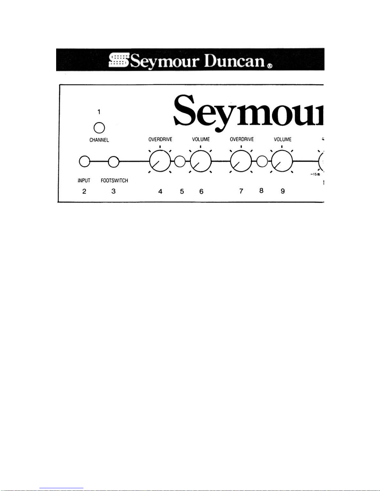
1) CHANNEL SELECTOR BUTTON: This push button lets you change channels
manually. The L.E.D.'s show you which channel is "on". If you prefer to use a
footswitch, use the channel selector button to put the amp in the green L.E.D.,
channel first; then the footswitch will operate.
2) INPUT JACK: This is where you plug in your instrument.
3) FOOTSWITCH: This jack accepts a stan dard 1/4" guitar cord and standard
footswitch (not supplied). When hooked up, the footswitch allows you to change
channels and to take advantage of the independent volume and overdrive
controls.
The optional Seymour Duncan footswitch with built -in L.E.D. will glow only when
you’re playing in the red channel.
Some amps produce a loud "pop" through their speakers when channel
switching. The Convertible Amp uses a channel switching circuit built into the
preamp that is isolated from other electronics. No annoying pops will occur when
changing channels.
4) OVERDRIVE, CHANNEL 1 (RED): This control dictates the amount of preamp
distortion and influences the amount the volume you want to add to your signal.
The lowest setting gives the cleanest signal and lowest volume. The highest
setting gives the most distortion and highest volume.
Page 6
5) VOLUME, CHANNEL 1 INDICATOR (RED):
When your amp is in channel 1 and the power is on, this L.E.D. will glow.
Your Convertible Amp uses L.E.D.'s because L.E.D.'s will last up to 10 times
longer than regular bulbs. Under normal usage. your L E.D.'s should last 10
years or more.
6) VOLUME, CHANNEL 1 (RED): This control sends the signal volume from the
channel ' preamp to the power amplifier. For the cleanest signal, turn the volume
up high and keep the Overdrive low (but not off). For the dirtiest signal, turn the
volume down (but not off) and the Overdrive up high.
7) OVERDRIVE, CHANNEL 2 (GREEN): This control operates exactly the same
way as the Channel 1 (Red) Overdrive. With two sets of Volume and Overdrive
controls you can set the one channel with a clean rhythm sound and a distorted
lead on the other.
8) CHANNEL 2 INDICATOR (GREEN): When your amp is in channel 2 and the
power is on, this L.E.D. will glow.
Page 7

9) VOLUME, CHANNEL 2 (GREEN): This control operates exactly the same
way as the channel 1 (Red) Volume.
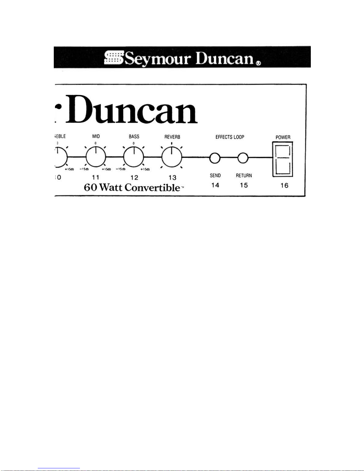
TONE CONTROLS: All three tone controls on your amp are "Activ e". This means
that you can either increase the tone level or decrease it. Most amps incorporate
"Passive" controls that allow you only decrease the tone levels.
The best way to use active tone controls is to start with all indicators at 12 o’clock
boost or cut in the areas you want to change.
10) TREBLE: This control lets you change the high-end response of your amp.
Turning the dial clockwise increases the high-end response up to 15db. Turning
the dial counterclockwise cuts the high-end response up to 15db.
11) MID: This control lets you change the volume of midrange response of your
amp. Turning the dial clockwise increases the level of midrange response up to
15db. Like the other tone controls, 12 o'clock is "flat" - no increase or decrease in
the tone response level.
12) BASS: The control lets you change the level of low-end response of your
amp. Turning the dial clockwise boosts low-end response up to 15db. Turning
the dial counter-clockwise Cuts the level of low-end response.
13) REVERB: This control lets you set the amount of reverberation you want in
your sound. Turn the reverb control clockwise to increase the amount of reverb
and counterclockwise to decrease. All the way counterclockwise is off.
Effects Loop: Use this circuit with your effects for the least amount of hiss. In
older design amps, players had to plug their guitars into effects and plug the
effects into the guitar input jack on their amps. With the Convertible 60 Watt
Amp, you can plug your guitar into the guitar input jack and run your effects
through the Effects Loop for the least noise and least unwanted distortion. Level
output is compatible with rack mount effects, not floor batterytype effects.
14) SEND: The Send on your amp should be connected to the input of your
effect using a normal guitar cable. You can also use this jack to slave into other
amps without affecting the signal in your 60 Watt Convertible Amp.
15) RETURN: The return on your amp should be connected to the output of your
effect using a normal guitar cable. You want the signal to come OUT of your amp
INTO the effect. And OUT of the effect INTO your amp.
16) POWER: This switch is what gets your amp going, and turns it off.
Page 8

1. FUSE HOLDER: The fuse is located in the cap of the fuse holder. If the fuse
fails, it must be replaced with one that provides proper current protection or you
will void the warranty. The proper fuse rating for the 110-120 v.a.c. Convertible
60 Watt Amp is 3.15 amp Slo-Blo @ 250 v.a.c.
Before removing the fuse cap, UNPLUG THE POWER CORD FROM THE WALL
A.C. OUTLET. After checking the fuse and replacing the cap, you can plug the
amp back into the wall.
To remove the fuse cap, simply use a small blade screwdriver and turn the cap
counterclockwise. To replace the fuse cap, make sure the fuse is snugly seated
in the cap, push fuse and cap into the fuse hole, and turn the fuse cap clockwise
using a small blade screwdriver.
Fuses do not wear out; they do not deteriorate with age. Fuses are protection
devices that protect the electronics from damage if there is a serious electrical
problem. If your amp repeatedly has fuse failures, check pages 1415 for the
troubleshooting tips.
Page 9

2) POWER CORD: Plug this cord into the electrical socket for a.c. power. DO
NOT CUT OFF OR DEFEAT THE GROUNDING PIN.
3) 4 OHM SPEAKER JACK: Use this jack to match the amp impedance to the
input of a 4-ohm speaker. Proper impedance selection will give you maximum
power and maximum damping.
4) 8 OHM SPEAKER JACK: Use this jack to match the amp impedance to the
input of an 8-ohm speaker. The Seymour Duncan Convertible Speaker that is
built into the 60 watt Combo is an 8-ohm speaker.
You can use both speaker jacks at the same time with different speakers. The
Convertible Amp's strong transformer can handle any load with no damage.
5) SLAVE: Use this jack for patching the output signal of the amp directly into a
mixer, tape recorder or another amp. Just use a regular guitar cord from the
Slave Out to the guitar input of the other unit. The circuit is w ired after the output
stage so all tone; volume, overdrive and reverb controls will affect the outgoing
signal. Output is one volt at full power. Impedance is 4.7k ohms.
Page 10

Page 11

Page 12

Page 13

Page 14

MODULE ARRANGEMENTS
Modules are a feature to let you create your own sounds. Each module is
actually part of the preamp, so you can radically modify the tone characteristics.
The module in the red L.E.D. channel is located on the right as you look at the
rear of the amp. This channel is optimized for lead playing by the internal electronics in the amp.
The module in the green L.E.D. channel is located on the left as you look at the
rear of the amp. This channel is optimized for rhythm playing by the internal
electronics in the amp. To remove and replace modules, follow the steps under
"Changing Modules".
Here is the way that modules are arranged when 60 watt Convertible amps are
shipped.
Below are just some of the module arrangements you can try for different
sounds. Your dealer has a wide selection of modules for you to choose from that
you can use to customize your sound. And each year, new modules will be
developed and offered for sale.
Page 15

Page 16

CHANGING MODULES
Both factory installed preamp modules are located on the right hand rear of the amp.
Changing modules is quick and easy. Dramatic tone changes are possible when you try
new modules. To remove and replace modules, just follow these easy steps.
TO REMOVE
1.UNPLUG YOUR AMP from the power outlet.
2. Let the amp cool down for one full minute.
3. Firmly grasp the module spring retainer with your finger and thumb.
4. Lift up and toward you. The spring will release its tension on both modules.
5. Firmly grasp the module you want to replace by its handle and slowly pull toward you.
TO REPLACE:
1. MAKE SURE THE AMPLIFIER IS STILL UNPLUGGED.
2. Choose the module you want to install and grasp its handle.
3. Align the module plug to be installed in front of the receptacle in the channel you have
selected.
4. Slowly insert the module into the receptacle. Apply moderate pressure until You feel
the module is seated snugly.
5. Repeat steps 2 through 4 for the other channel's module if you want to replace that
one, too. When you have finished changing modules, double-check both modules to
ensure they are still snug in their receptacles.
6. Firmly grasp the module spring retainer and move away from you and up until it clears
the module handles, When in its proper position, the retainer will rest on top of the
module handles and hold them tightly in place.
7. Make sure the Volume controls are at a low setting and plug the amp into the power
outlet-
8. Turn on the power switch and wait one minute for all the tubes to warm up.
9. Plug in your guitar and check out the new sound you've created.
Page 17

TUBES
Just like all other parts in the Convertible amps, the tubes were selected for
providing the most musical tones. Tubes can be temperamental, but there are
things that can be done to avoid problems.
Module Preamp Tubes
Convertible amps are designed with EL-34 power tubes. These tubes will give
you the sweetest tone and are generally more "musical".
The EL-34 tubes installed in your amp are from Groove Tubes. They are
specially matched for cathode current to reduce hum and noise - especially
noticeable when playing quiet passages and in the recording studio. Clipping
characteristics are also matched to give the most sustain and harmonic balance.
All notes will decay together. When you replace your output tubes, make sure to
ask for matched sets to keep your amp sounding like new. A bias balance control
under the amp lets you adjust for minimum hum when you replace power tubes.
Bias Balance Adjustment:
1. Turn both volume and overdrive controls off.
2. Remove guitar cord from input jack.
3. Listen for hum level.
4. Turn bias balance control clockwise for lowest hum. If hum increases while
turning clockwise, turn the control counter-clockwise until the hum reaches its
lowest audible level.
If you re transporting your amp often and subjecting it to rough handling, there
are other power tubes that will better withstand the abuse.
The 6CA7 is an industrial version of the EL-34. While the tone is not as sweet as
EL-34's, it is better suited to handle bumps and bangs. You can plug 6CA7 tubes
directly into the power tube sockets because the amp bias will not have to be
changed. If you try 6CA7 tubes, just make sure you adjust the bias balance
described above.
The 6L6 and 6550 tubes will also stand up to road knocks. Like the 6CA7 tubes,
they are not as musical as EL-34's. You'll notice a harder sound. Although the pin
matchups allow you to directly plug 6L6 and 0 tubes into the power tube sockets,
you'll need to have a service technician replace a bias resistor one that's value
matches the 6L6's or 6550's. See your authorized service center for cost.
Page 18

Module Preamp Tubes
The 1 2AX7 Tungsram tubes will give you the least amount of noise and the
sweetest tone. However, they can develop a micro phonic ringing when subjected
to a lot of bumps from travel ing. Here are some ways eliminate micro phonics.
1. Polish 1 2AX7 tubes are constructed differently than the Tungsrams. Although
Polish tubes are noisier and harder sounding, they are less subject to micro
phonics. Radio Shack and other companies offer Polish tubes. "Made in Poland"
is stamped directly on those tubes so you can be sure where they come from.
2. Try using a FET or IC module. Because neither of these are tube designs,
you'll get no micro phonics. For a warmer tube sound, use an FET module. I f you
are after a harder solid-state sound, use an IC module.
If you're involved in a touring schedule and you want to avoid tube related
problems, bring some extra tubes with you for all your equipment.
TROUBLESHOOTING
The following table should enable you, with little or no knowledge of electronics,
to isolate the cause of some problems you may experience with your amplifier
and the steps required for repair. Most causes of impaired amplifier performance
are due to minor problems or irregularities, wh ich can be easily corrected by you.
However, if you cannot identify the cause of the problem using the table below,
or if it indicates your amplifier to be defective and in need of repair, return the unit
to your authorized Seymour Duncan Service Center or call (805) 964-9610 for a
Return Authorization number.
Symptom Probable Cause Remedy
Amplifier does not come
on when power switch is
"ON".
1) Power not connected
1) Ensure power cord is
plugged into power outlet
2) Check amp fuse;
2) Blown amp fuse
replace if blown with
250VAC 3.15 amp
SLO-BLOW
Page 19

No sound coming from
speaker(s), (no audible
amplifier hum).
Loud amplifier hum
Amp blow s a fuse after
several minutes of
operation
Amp blows a fuse
immediately after it is
switched on
Distorted sound coming
from only one channel
3) No source voltage
4) Defective ON/OFF
power switch
1) Master Volume and/or
Over drive control levels
set too low
2)Speaker output plug
disconnected
3) Instrument
pickup/electronics may
be defective.
4) Defective speaker(s)
5)Volume controls on
your instrument are down
6) Defective center
driver tube
12AX7
7) Module(s) not installed
in rear of unit
8)Effects hooked up
backwards
9) Defective tube in
module
1) Instrument connecting
cable
not properly grounded
2)EL-34 power tube
shorted
1) EL-34 power tube
defective
2) Problem persists
1) EL-34 power tube
defective
1)Overdrive control level
set too high
3) Verify power source
with something you know
works
4) Return unit to dealer
or factory for repair
1) Increase control
level setting(s) to "4" and
listen
2)Connect output plug to
4 ohm or 8 ohm speaker
jack
3) Unplug cable from
instrument and touch tip
of plug; if hum is heard,
replace instrument with
one known to operate
properly
4)Verify speakers
operate properly using
another amp
5)Increase settings and
listen
6) Replace 1 2AX7
7) Install modules
8)Properly hook up
effects with effects loop
9)Replace module tube
1)See that connecting
cable is plugged into
instrument
2)Replace EL-34.
Readjust Bias balance
1) Replace EL-34.
Readjust Bias balance
2)Return amp for repair
to dealer or factory
1) Replace EL-34.
Readjust bias balance
1) Reduce control level
setting
Page 20

Distorted sound coming
from both channels
No reverb coming from
amplifier
No reverb sound
Channel selector
Footswitch does not
change channels
Feedback, ringing
2)Defective preamp
module
1) Overdrive control
levels set too high
2) Speaker output wires
to amplifier shorted
3) Pickup, instrument, or
connecting cable may be
defective
2) Replace module with
one known to operate
properly
1) Reduce control level
settings
2) Replace speaker cord
3) Substitute cable and
instrument with one you
know operates properly
4) Verify speakers
operate properly by
connecting speaker plug
4) Defective speaker(s)
to speaker outlet jack on
another amp. If speaker
is defective return unit to
dealer or factory for
repair.
1) Reverb control level
set too low
2) Reverb output wires
not connected to reverb
tank
3) Defective internal
spring reverb unit
4) Defective reverb Send
or Return circuits
5) Springs are stuck
1) Increase control level
2) Ensure output wires
properly connected to
reverb tank
3) Replace reverb spring
4) Return to dealer or
factory
5) Tap the reverb tank
with your hand.
1) Use channel mounted
1) Channel selector on
amplifier set to channel 1
position
channel selector to set
the amp in channel 2
(indicated by the green
LED)
2) Substitute footswitch
2) Defective footswitch
with one known to
operate properly
3) Defective internal
channel switching in amp
3) Return amp to dealer
or factory for repair
1) Master Volume and/or
Over drive controls set
1) Lower levels
too high
2) Micro phonic pickups 2) Wax pot pickups
3) Micro phonic tube
sound
3) Replace tube in
module
Page 21

 Loading...