

Page 1
Gus G. FIRE™ Blackouts System
Congratulations on your purchase of the Gus G. FIRE™
Blackouts System. By combining a pair of passive
humbuckers with a high-output, low-noise Blackouts™
active preamp, this system blends the rich tone and
expressive character of traditional pickups with the
power and punch of Blackouts™. It’s the most organicsounding active pickup set you’ve ever heard.
Wiring Diagram for:
AHB-11S Gus G. FIRE™
Blackouts System
5427 Hollister Ave., Santa Barbara, CA 93111
seymourduncan.com • (805) 964-9610
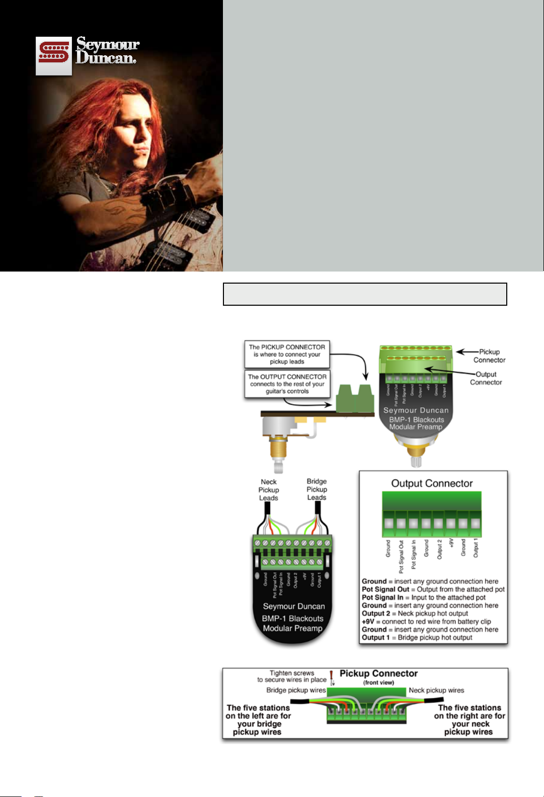
The Solderless Connector Stations
The System’s preamp has two easy-to-use
solderless wiring connectors: the ten-station Pickup Connector and the eight-station
Output Connector.
The Pickup Connector is where you’ll insert the bare-wire pickup leads from your
passive pickups. Just match the wire colors of the pickups’ wires as indicated in
these diagrams.
The Output Connector is where the preamp
connects to the rest of your guitar’s controls. Output 1 and Output 2 are the hot
outputs for your bridge and neck pickups,
respectively. The +9V station is where you’ll
connect the red wire from the battery clip.
Connecting wires to the stations is simple:
Just insert the bare wire into the station and
tighten the screw to lock it into place.
Installing the Preamp
1. Draw a diagram of your guitar’s wiring
for reference.
2a. If you’re migrating from a passivepickup setup, remove your output jack and
all of the volume and tone potentiometers
from your guitar. You’ll be replacing the jack
with the included stereo output jack and
replacing your potentiometers with the 25K
pots included in this package.
2b. If your guitar already has an active
system, remove the battery. Clip and strip
the end of the battery clip’s red wire,
leaving as much wire length extending from
the battery clip as possible. Do the same for
any output or ground wire that was previously connected to the potentiometer that
the new preamp will replace. This will prepare everything for solderless connections.
The Pickup Connector and Output Connector
Continued on other side.
P/N 501020-155
Page 2
3. The new preamp will take the place
of one of your volume pots. Install the
Blackouts Modular Preamp through the
hole where your original potentiometer
was located. Depending on the diameter of your existing pot, a reamer may
be required to open the hole. Use the
washer and nut to secure it snugly to
the guitar.
4. Install all remaining 25K potentiometers.
5. Install the battery clip, and connect the
red wire from the battery clip to the +9V
station on the Output Connector. (Don’t
install a battery yet.)
6. Insert the wires from all pickups into the
Pickup Connector. Tip: Tweezers can make
this step go much faster. Tighten the connec-
tor screws using the included screwdriver.
7. For the remainder of your guitar’s wir-
ing, either follow the diagram below, or visit
www.seymourduncan.com/wiring to find
the control setup that matches your guitar.
8. Once the wiring is complete, install a
fresh 9-Volt battery (not included) into the
battery clip, plug your guitar in, and fire
it up!
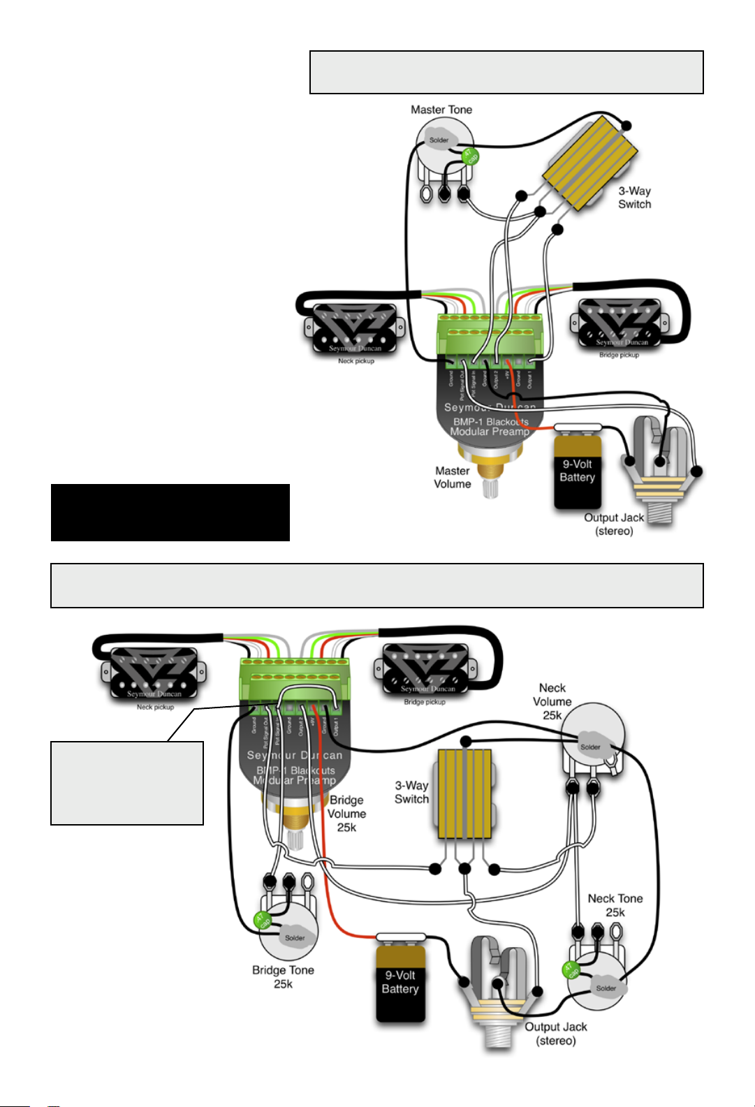
One Volume, One Tone, and a Pickup Selector Switch
Simple Setup
For more wiring diagrams, visit
www.seymourduncan.com/wiring
Two Volumes, Two Tones, with Blackouts Modular Preamp as the Bridge Volume
The Bridge pickup output
goes directly into Pot
Signal In, along with the
connection to the bridge
tone control.
Les Paul® Wiring
© 2011 Seymour Duncan. Seymour Duncan is a registered trademark.
Les Paul® is a trademark of Gibson USA with which Seymour Duncan is not affiliated.
 Loading...