

dunaco Stereo 160 Owner's Manual
Stereo 160
Vacuum Tube Amplifier
Owner's Manual
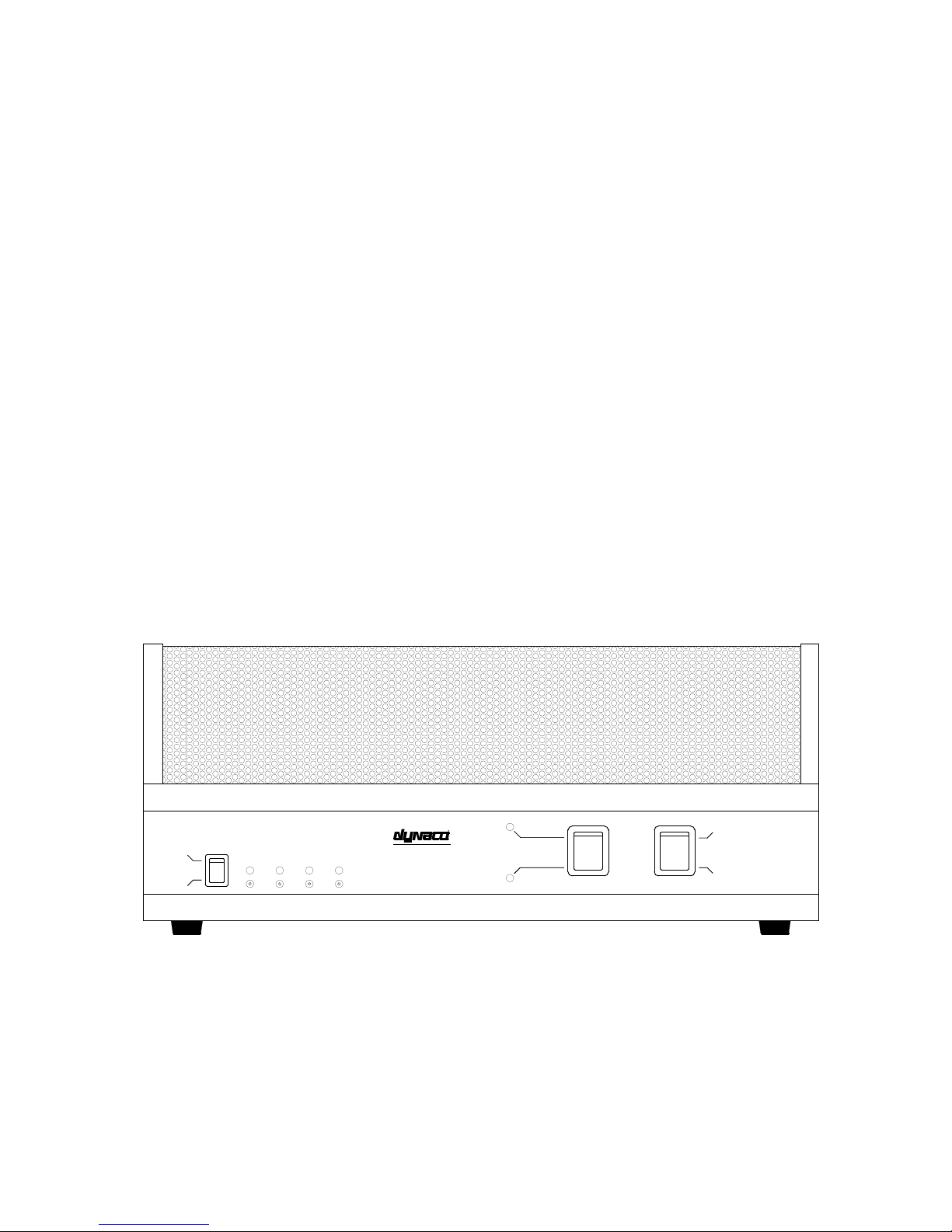
ON
BIAS DISPLAY
OFF
OUTPUT TUBE BIAS ADJUSTMENT
LEFT CHANNEL RIGHT CHANNEL
V3 V4 V7 V8
R
STEREO 160
Vacuum Tube Power Amplifier
TRIODE
ULTRALINEAR
Stereo 160 Vacuum Tube Power Amplifier
POWER ON
POWER OFF

Contents
Introduction ........................................................................ 3
Vacuum Tube Warm Up .................................................... 4
Rear Panel Inputs and Outputs ........................................... 4
Input Sensitivity Setting ..................................................... 5
Power On/Off Indicators and Fuses .................................... 6
Triode/Ultralinear Modes ................................................... 7
Bias Adjustments - general ................................................. 8
Output Tube Bias Adjustment Procedure ........................... 9
Burn-In Procedure for New Output Tubes ......................... 10
Tube Replacement .............................................................. 11
Alternate Tube Types ......................................................... 13
Minimizing Noise in the System ........................................ 14
Warranty ............................................................................. 15
Stereo 160 Specifications ................................................... 16
Schematics .......................................................................... 17
Stereo 160 PC Board Parts List .......................................... 20
Please read this manual thoroughly before operating your new Stereo 160.

Introduction
Congratulations on your purchase of the Dynaco Stereo 160 Amplifier. This product
was designed to provide the highest combination of quality and value available, which
is the Dynaco tradition.
The Dynaco Stereo 160 amplifier uses special power supply buffering circuitry - found
in no other brand of amplifiers in this class. We have included a separate buffer circuit
for each of the input and driver tubes in the Stereo 160, allowing each amplification
stage to function more independently, (as if each one had its own separate power
supply). This method contributes significantly to the sonic clarity of the Stereo 160.
The Stereo 160 can be operated in either Triode or Ultralinear mode. Switching
between the two is easily done via a front panel switch.
State-of-the-art biasing circuitry allows you to easily attain precision bias settings for
each of the output tubes through front panel adjustments and indicators.
Another special feature of the Stereo 160 is its adjustable Input Sensitivity. This allows
the Stereo 160 to be connected directly to components having vastly different output
signal levels. The user can, for example, connect a CD player directly to the Stereo 160
without using a preamplifier.
You will find the Stereo 160 sounds better than the large majority of other amplifiers both solid state and vacuum tube designs - regardless of price. Your Stereo 160 was
designed and built entirely in the USA. We are proud to offer this outstanding amplifier
to discerning audiophiles the world over.
Dynaco Engineering Group

Vacuum Tube Warm-Up
Although a vacuum tube power amplifier begins to work in as little as 15 seconds after being switched on,
it is important to allow a 3 minute warm-up period before using the amplifier.
Output tubes can be slightly damaged each time they are forced into use before being warmed-up,
resulting in non-optimum sound and shorter tube life. If one listens to music during the warm-up period,
one may notice that the output volume of the amplifier changes as the tubes warm up.
We recommend that you wait at least 3 minutes after switching the amplifier on before using it. On the
Stereo 160, waiting about one minute after the four bias lamps turn from “green” to “off” is a proper
(minimum) warm-up period.
(See section entitled Bias Adjustments - general)
Rear Panel Inputs and Outputs
Inputs
There are two input jacks located on the rear panel of the amplifier - labeled Left and Right. These
connect to your preamplifier Line Outputs.
Never plug in, or disconnect, interconnect cables from other components to the
amplifier when it is turned on. To do so could cause a fuse to blow or even damage the
speakers.
Outputs
Match the impedance of your speakers to the amplifier by connecting the positive (+) speaker wire of
each channel to its corresponding 2 ohm, 4 ohm, or 8 ohm red binding post. Connect the negative (-)
speaker wire from each channel to its corresponding black binding post.
You can safely connect or disconnect speaker cables to/from the amplifier while it is turned on. It is best
at those times to turn down volume control(s) on any equipment connected to the amplifier inputs.
(Nevertheless, care should be taken to not touch bare speaker wires together if one end of the speaker
cable is connected to the amplifier.)
4

Input Sensitivity Setting
The Input Sensitivity adjustment is located on the rear panel, to the right of the input RCA jacks. This
feature allows you to select how large of an input signal will result in full power output of the amplifier.
The Input Sensitivity adjustment can be used to “match” the Stereo 160 inputs to your preamplifier
outputs. You can set it so that the preamplifier volume control can be turned all the way up before
clipping occurs in the Stereo 160. This also allows you to connect audio components, such as CD
players, directly to the Stereo 160 without using a preamplifier, if desired.
Most power amplifiers have input sensitivities in the range of 1 to 1.5 volts. If an amplifier has an input
sensitivity of 1 volt, this means that an input signal level of 1 volt will produce the full rated output power
of the amplifier.
The Input Sensitivity on the Stereo 160 can be adjusted as follows:
Set at Normal (12 o’clock) the input sensitivity is approximately 1.5V.
Set at Low (9 o’clock) the input sensitivity is approximately 5.5V.
Set at High (3 o’clock) the input sensitivity is approximately .5V.
Set fully clockwise, the input sensitivity is under .3V.
5
Power On/Off Indicators and Fuse
The Stereo 160 Power On/Off indicator is either the Ultralinear (red) lamp or the Triode (amber) lamp.
The lamp which is lit when the Power On/Off switch is turned on will depend upon the Triode/Ultralinear
switch position.
During the first minute or so after the Stereo 160 is first switched on, all four output tube bias indicator
lamps glow green. As the unit warms up, these lamps should go off, indicating the unit is ready for use.
If the bias indicator lamps remain green (or turn red) after the initial warm-up period, a low or high AC
line voltage condition may be indicated. The AC line voltage varies from country to country, city to city,
house to house, and even the time of day in many locations. It can also be affected by common
appliances such as electric heaters, microwave ovens, clothes dryers, etc. Therefore, you may need to set
the output tube bias adjustments to suit your own location. (See section entitled Bias Adjustments -
general.)
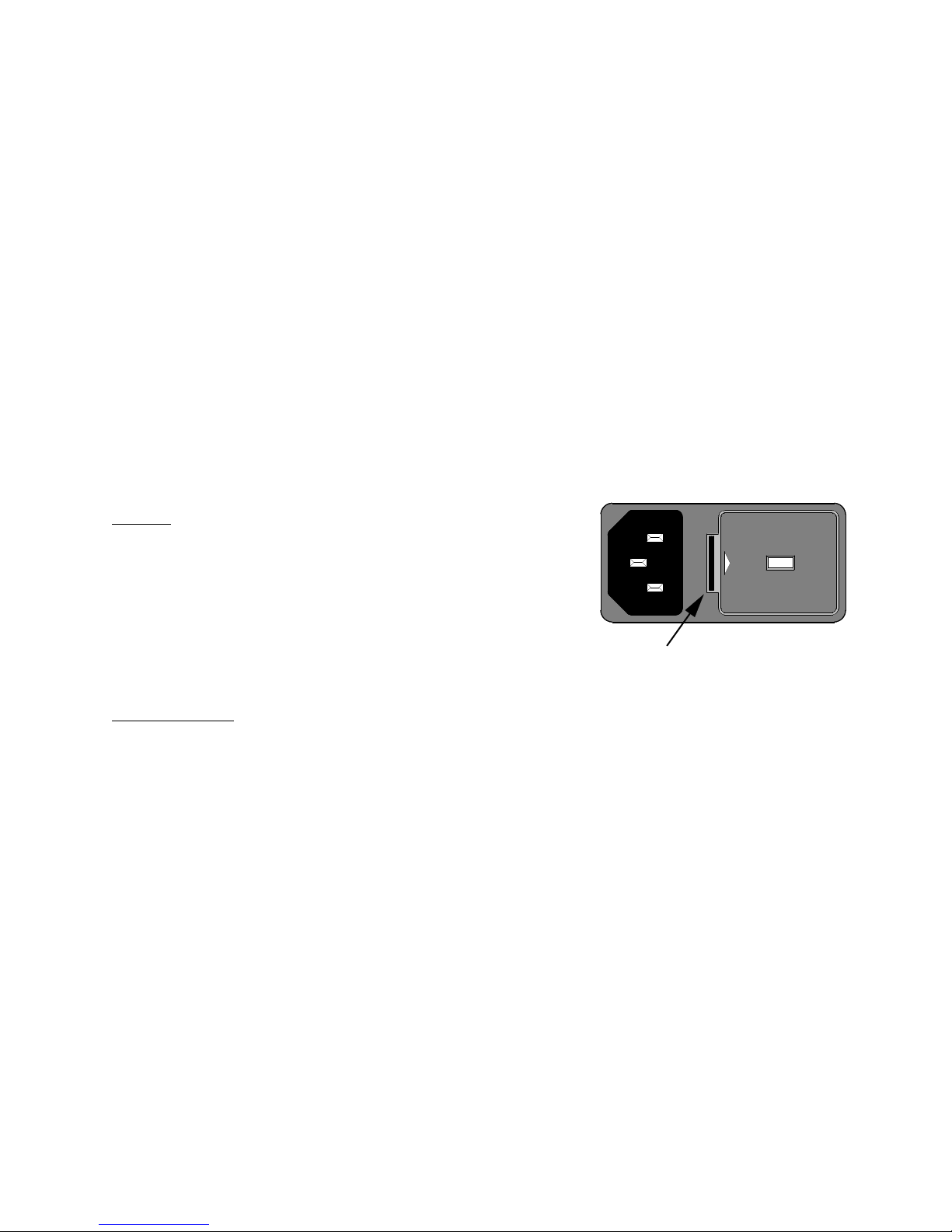
Fuses
AC Line Fuse (F1):
10 Amp Fast-Blow - 100 or 120VAC
120
120
120120
5 Amp Fast-Blow - 220 or 240VAC
To remove the AC line fuse, use a small screwdriver to
push forward the tab near the center of the Power
Entry Module.
PUSH TAB TO RELEASE FUSE HOLDER
Output Protection (F2, F3):
1/2 Amp Fast-Blow (regardless of line voltage)
F2 (left channel) and F3 (right channel) protect the Output Transformers from damage due to a possible
shorted output tube. If either output tube in one channel shorts, the fuse for that channel will blow.
Although shorted output tubes should be considered rare, the fuse elements themselves become brittle
with age and sometimes fail under normal use. Always keep spare fuses for your Stereo 160 at hand.
Always remove the power cord when accessing the AC line fuse.
6

Triode/Ultralinear Modes
The Ultralinear mode is usually considered to be the “normal” mode of operation. The overall power
rating of the amplifier is specified for Ultralinear mode.
In Ultralinear mode, the screen grid of each output tube is connected to a tap on its associated output
transformer. When Triode mode is selected, the screen grids are (instead) connected to the plates of their
respective output tubes.
Operating the amplifier in Triode mode reduces the amplifier output power to about 1/2 of that in
Ultralinear mode. Triode mode also softens the clipping characteristics of the amplifier so it seems to
need less output power. Triode mode produces more lower-even order harmonics, whereas Ultralinear
mode produces higher-odd order harmonics.
Some people prefer Triode mode; some people prefer Ultralinear mode. The choice of which mode to use
is also often influenced by the sonic characteristics of the speakers being used.
You can listen and compare to determine which mode sounds best to you for your chosen music material
and speakers.
7
 Loading...