


Du Mont 3
DU MONT TYPE 180
Twenty-two Tube, AC, Superheterodyne, Television Receiver
GENERAL FEATURES
No expense has been spared in the production of these
receivers and every up-to-date television and radio
development has been incorporated. These receivers are
classed as "Electrostatic and Direct Vision." Electro-static
indicates that the entire deflection system is electrostatic
and since the picture is viewed direct, without the use of a
mirror, lens or other device, it is referred to as Direct
Vision. The latter ensures clarity, brilliance and the widest
angle of vision. Steady, clear cut, black and white pictures
that are large enough for all the family to enjoy at one
time are secured by the use of a fourteen inch cathode-ray
A separate high fidelity section brings superb
reproduction of the sound channel which is associated
with the picture. A single control tunes both the sight and
the sound channels so the receiver is no more difficult to
operate than an ordinary broadcast receiver, To the above
features add its compact size, minimum number of
controls and simple straight forward layout and you will
have an idea of the first commercial television receiver
which we believe you will find easy to install and service
in spite of the apparent complexity of the subject
Television.
tube which furnishes a picture eight by ten inches
TECHNICAL INFORMATION
Frequency Ranges – Four Television Channels provided, present alignment as follows:
AUDIO VIDEO
STEP STATION SIDEBAND CARRIER CARRIER
A NBC Single 49.75 45.25
B CBS Single 55.75 51.25
C …… …… …… ……
D NBC Double 49.75 46.5
Power Ratings
Power supply 110 to 120 volts, 50 to 60 cycles, 250 watts.
Audio output, maximum 4.25 watts.
MECHANICAL SPECIFICATIONS
Cabinet Dimensions
Height …………………………………… 24 inches
Width ……………………………………. 15 ¾ inches
Depth ……………………………………. 25 inches
Chassis Dimensions
Height …………………………………… 20 ¾ inches
Width …...………………………………. 13 ¼ inches
Depth ……………………………………. 24 ¼ inches
CONTROLS
Operating Controls…………………………6
Adjustment Controls……………………….7
Types 181, 182, 183
These receivers have the same operating controls as the
type 180 and therefore will not be covered separately
Type Purpose
1853 …………… R.F. Amplifier
6J5M ....….…….. R.F. Oscillator
1852 …………… 1
1853 …………… 1st Video I.F Amplifier
1852 …………… 2nd Video I.F. Amplifier
6H6M ………….. 2
1851 …………… 1st Video Amplifier
6V6G ………….. Video Power Amplifier
6J7G …………… 1
6J7G …………… 2
6Q7G ………….. 2
6V6G ………….. Sound Power Amplifier
6J7G ………….… Horizontal Synch Separator
6AD5G …………. Horizontal Sweep Oscillator
6R6G ...……….… Horizontal Sweep Amplifier
6J7G ………….… Vertical Synch Separator
6AD5G …………. Vertical Sweep Oscillator
6R6G ....………… Vertical Sweep Amplifier
2Y2 ..........…….... 4100 Volt Rectifier
5X3 …………….. 1600 Volt Rectifier
5Z3 .....………….. 350 Volt Rectifier
114-9-T .....……... Cathode-ray Tube (14")
TUBE COMPLEMENT
st
Detector
nd
Video Detector
st
Sound I.F. Amplifier
nd
Sound I.F. Amplifier
nd
Sound Detector and Amplifier

Du Mont 4
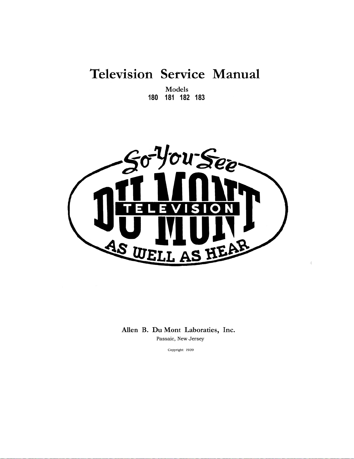
CIRCUIT ARRANGEMENT
A simple straight line layout is used in these
receivers that should prove extremely helpful to the
serviceman. Viewed from the front, the video receiver is
on the left side of the chassis and the sound receiver is on
the right. Fig. No. 1 shows the front controls and the
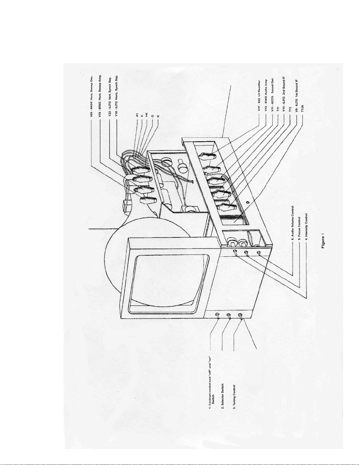
sound receiver while Fig. No. 2 shows the rear
adjustments and the video receiver. The top portion of the
chassis contains both sweep circuits along with the
modulating circuit of the cathode-ray tube. To prevent
confusion each side is considered separately, half
appearing in Fig. No. 1 and the remainder in Fig. No. 2.
The seven auxiliary controls shown in Fig. No. 2 are
provided for the use of the installer and serviceman.
These controls are necessary to make the final alignment
of picture size and positioning when
the receiver is installed under the operating conditions
imposed by the .earth’s magnetic field. and the power
supply line voltages. Once properly set these controls do
not need adjustment and since they. were not provided for
the owner’s use we suggest that the dealer or serviceman
seal the back of the cabinet as it is not possible to tamper
with the controls when the back is in place. The use of the
parts and tubes shown in Fig. No, 1 and Fig. No. 2 can be
checked by comparing the "V” numbers, etc., with the
schematic drawings which are furnished in the back of
this manual. Four separate schematic drawings have been
provided which, due to their size, will be found more
readable than a single drawing.
CAUTION AND WARNING
The set is equipped with a safety switch which
automatically opens upon the removal of the back of
the cabinet. This protects the operator from dangerous
high voltages which would otherwise be exposed.
The serviceman that is engaged installing or
servicing television receivers is urged to take all
precautions and run no unnecessary risks. The high
voltages that are necessary with this type of equipment
are very dangerous and should not be approached in a
careless manner.
It is better to shut the set completely off between
adjustments than to suffer a painful or even a
dangerous burn.
Large cathode-ray tubes operate at high-voltages and
hence are evacuated to a very high degree of vacuum.
Therefore the atmospheric pressure on the glass can run
into tons depending on the size of the tube. A collapse
therefore is as bad as an explosion and all cathode-ray
tubes should be handled with care. The Du Mont
Laboratories have gone to great expense to provide a
cathode-ray tube that is safe for the home and the
structural design results in its ability to stand tests nearly
twice as severe as usually employed. The serviceman,
however, should observe the following rules as he will
probably be the only one to handle the average tube.
1. Be careful in handling the tube.
2. Watch the use of tools near the tube.
3. Don't scratch the surface of the glass.
4. Don’t stand the tube on a metal surface or in any
other way cause certain parts to be quickly
heated or cooled.

Du Mont 7
INSTALLATION OF RECEIVER
Antenna Installation
In the installation of television receivers the proper
antenna is a necessity. Successful installations will result
from attention to details, while slipshod and careless work
will bring only poor customer satisfaction and repeat
calls. There is nothing difficult about the installation of
television aerials, a little patience and experience is all
that is required. Regular broadcast aerials in the majority
of cases will be found useless. Impress this upon the
owner and make a satisfactory installation regardless of
what other equipment he already has. Satisfactory picture
reception is what both of you require for the completion
of the installation.
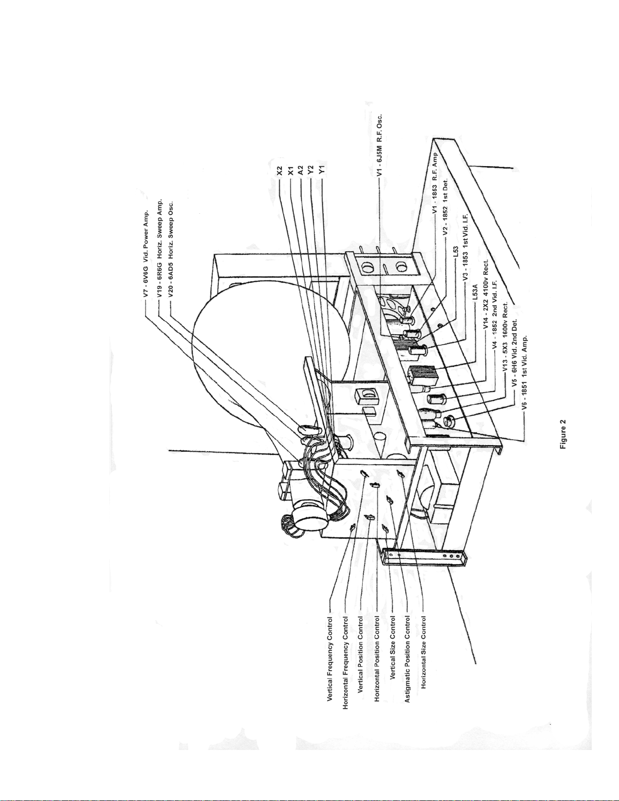
The Dipole Antenna
The Dipole form of aerial is generally satisfactory; it
consists of two metal rods, each approximately five feet
long and placed on a line with each other. Extreme
accuracy in the length of these rods is usually not
necessary and if the receiver is located very close to the
transmitting station it may be found advisable to cut down
the length of each rod. The simple dipole aerial is shown
in Fig. No, 3.
The Lead-In
The most popular lead-in from the dipole to the
Television receiver will be a twisted pair as it is
inexpensive and generally satisfactory in locations where
the. signal is strong. The length of this lead is usually not
of extreme importance, It is best to get the Dipole located
in the clear and as. far from electrical interference as
possible than to limit its location by using a theoretical
exact length feeder, The twisted pair should be soldered to
the lugs on the Dipole as a good connection is essential
and necessary since several changes in the position of the
antenna may be required for best results. The other form
of lead-in is the coaxial line such as the Amphenol No.
72. This form of feeder should be used in installations
where the length of the lead-in is too long for satisfactory
work with the twisted pair and again where the
installation is at an extreme distance and every bit of
energy picked up must be delivered to the receiver.
Polarization
If the dipole is mounted horizontally it is said to be
horizontally polarized, and if vertical it is vertically
polarized. Since the physical location materially effects
the aerial no specific form can he advised and we can
merely suggest that you start by using horizontal
polarization and change if necessary to produce the best
results.
Location of the Antenna
Whenever possible the Dipole should be erected so
that it is in line of sight with the transmitter. This do es no t
mean that no signals can be secured where a direct view
of the transmitter cannot be obtained. Surprising results
are often secured on these high frequencies and no
concise rules can be assigned to this work. If the location
is on a street, having heavy traffic there may be
considerable noise level due to automobile ignition
systems. In this case, locate the Dipole to the rear of the
building and away from the source of the noise as far as
possible. In the case of' electrical machinery over which
you have no control, the same method can be employed
along with the utilization of the directional effects of the
aerial which will be covered later.
Room Illumination
Whenever possible the receiver should be so placed
in the home that a direct glare from either natural or
artificial light does not fall upon the face of the cathoderay tube. The received picture may be viewed under a
variety of conditions where it is not always convenient to
darken the room completely. Adjustments made to meet
these conditions will not cause damage to the receiver.
Viewing the pictures in as dark a room as possible is
always at an advantage as it permits the setting of the
Intensity and Contrast controls in a manner that will give
picture tone values more correctly relating to those
actually used in the studio from which the picture is
transmitted.
Installation Process.
It is a good plan to proceed as follows with the
installation,
l. Erect the Dipole antenna in the clear. Start by using
horizontal polarization (mount the rods horizontal) and
turn them until their plane is at right angles with the
location of the transmitter
2. Adjust the receiver to produce a picture.
3. Return to the antenna and make final adjustments for
best signal strength and removal of ghosts, etc.
Ghost Effects
Where the picture appears to be duplicated and
slightly displaced, the additional picture is referred to as
a ghost. This effect is usually due to the refection of the
signals and can be cured by the slanting or rotating of the
Dipole or the use of a reflector or reflectors. If after all
possible positions have been tried, the ghost still exists it
will be necessary to change the location of the antenna
and try again.

Du Mont 9
Directional Effects
In the simple Dipole, directional effects are not very
pronounced, but it does have a rather sharp no-signal
radius and it is possible in some instances to materially
reduce interference by placing the offending source in this
area. If the installation of the receiver is being made at
quite a distance from the transmitter or if the signal level
is very low due to local conditions it is well to con sider
the use of a reflector. This is done by placing a rod, about
ten feet long, parallel with the Dipole and about 5 feet in
back of it. The directional effect of the Dipole remains the
same, namely at right angles to the plane. Signals coming
from the front will be greatly increased. In using
reflectors it is well to bear in mind, however, that any
signal approaching from the rear (where the reflector is
located) will be greatly attenuated. Fig. No. 4 shows
reflector added to the simple Dipole.
Operating Controls of the Receiver (Front)
First, become familiar with the controls on the front of the
receiver. Since the receiver has been tested before
shipment, probably only a few minor adjustments will be
necessary. Therefore before touching the adjustments in
the rear attempt to operate the set according to the
instruction sheet supplied the purchaser and make only
the adjustments required. These instructions are repeated
here to cover the possible lose of the sheet. Figure No.1
shows the front of the receiver with the controls
numbered and the use and the purpose of these controls is
as follows.
1. Marked CONTRAST, ON and OFF
This is a power switch for starting and stopping a set. It
also is the volume control of the picture signal. It should
be adjusted in conjunctio n with the intensity control (No.
4) to produce a picture of pleasing contrast to the user. If
the location is such that the signal received is very small it
may be necessary to use the full gain of the control, while
in a good location it may, have to be retarded
considerably. If the picture is not satisfactory the rear
controls must be adjusted as covered in a following
section.
2. Marked SELECTOR
This control is a four position switch provided for
covering four television channels. The present alignment
was given previously under the technical information
section.
3. Marked TUNING
Only one control is necessary to properly tune both the
sight and sound channels. Simply adjust this control until
the best reception of the sound is secured and at this point
4. Marked INTENSITY
The intensity or brightness of the picture is controlled by
this knob. It should be adjusted in conjunction with
Control No. 1 to get the best picture. Note: it is a good
plan to retard (turn to the left) this control when starting
the set. If about 15 seconds is allowed to elapse before
advancing this control it will prevent a small brigh t spot
from appearing on the screen which might eventually
darken the screen.
5. Marked FOCUS
This control is used to sharpen the individual lines of the
pattern and once set seldom requires further adjustment.
6. Marked VOLUME
This volume control adjust the audio volume and has no
effect whatever upon the picture
Rear Controls of the Receiver
As previously stated the adjustment of these controls is
necessary for the final alignment of picture size and
positioning, as the earth's magnetic field and power
supply line voltages vary with locations. The location of
these controls is shown in Figure No. 2 and th eir use will
be covered in numerical order. Proceed as follows:
remove the wood screws holding in the back of the
cabinet and pull out the back. The safety switch will open
turning the set off and since it is necessary to have the set
in operation while making these adjustments the switch
can be made temporarily inoperative. (A large battery clip
is convenient for this purpose.) Do not reach into the set
with the voltages on. (See Cautions and Warning.) There
is one adjustment that cannot be made by these controls,
that of rotating the Cathode-ray tube to cause the picture
to properly line up with the viewing opening. To remedy
this, turn the set off, remove the elastic band that grips th e
rear support and rotate the tube by hand in the correct
direction.
The function of the seven rear controls are as follows
1. Vertical Frequency Control
This controls the frequency of the vertical sweep. If the
picture is not steady and slips past at intervals, vertically,
this control should be adjusted until a steady picture is
secured.
2. Vertical Size Control
If the picture is too narrow and out of proportion
vertically this control will remedy the trouble.
3. Vertical Positioning Control
As its name indicates, this Control will move the pattern
vertically, allowing the picture to be placed directly in the
center of the opening.
the picture signal will be correctly tuned.


Du Mont 11
4. Astigmatic Positioning Control
This is adjusted in conjunction with Control No. 5 to
give the best possible focus on the corners of the picture.
5. Horizontal Positioning Control
This control positions the picture horizontally.
6. Horizontal Size Control
The width of the picture is adjusted by this control.
7. Horizontal Frequency Control
If no picture can be secured but modulation (dark and
light spaces) can be seen on the screen, the setting of the
horizontal frequency control is probably incorrect. Adjust
this control until the picture forms.
With the adjustment of these controls the installation
should be satisfactory. However, if the signal is weak or if
ghosts or noise is present, return to the dipole antenna and
make changes as previously suggested until the best
position for it is secured.
SERVICE
While the technique employed in servicing television
receivers is similar to ordinary radio practice, there is a
greater need for basic knowledge and the time will be
well spent that is used to study the fundamental principles
of television before attempting actual service work. For
obvious reasons it will be impossible to include
fundamental theory in this manual, however, since very
little data concerning the form of sweeps used in these
receivers is available, the following description may be
helpful.
Fig. 5 is a schematic diagram showing synchronizing,
signal separation and sweep circuits used in this receiver.
The two 6J7G tubes (V18 & V22) function as the
synchronizing signal separators. The outputs of the two
plates are fed their respective synchronizing windings of
the horizontal and vertical oscillation transformers. Linear
sawtooth deflection is effected using a 6AD5G triode as
an oscillator and a 6R6G triode as an amplifier.
Oscillations are generated as follows:
Let us consider first the low frequency vertical circuit.
Condenser C76 is charged from the power supply through
the resistor consisting of R64 and R65. R65 functions
mainly as an amplitude or size control, although it has
some effect upon the frequency of operation. Condenser
C76 charges to practically full power supply potential. As
a result of previous oscillations, a charge on condenser
C75 is held on the cathode, which gradually decreases to
zero through R59 as C76 is charging. This charge on C75
is high enough to hold the tube at cutoff. The grid of the
tube is at D.C. ground potential. As the cathode
approaches ground potential due to the discharge of C75
the 6AD5G triode becomes conducting. As plate current
flows C76 is discharged producing the return trace of the
sawtooth. The surge of plate current through the winding
of the oscillation transformer induces a voltage in the grid
winding of proper polarity to drive the gr id more positive,
C75 is charging to its initial value to cut off the flow of
plate current. As this action takes place, the plate current
surge decreases thereby applying less positive voltage to
the grid and increasing its cutoff action. Ultimately, the
tube is completely cutoff, the cathode is at its full positive
potential, and the charging cycle again begins. Resistance
R59 functions as both an amplitude and frequency control
since it determines the breakdown potential and the
frequency of recurrence of the oscillations in the plate
circuit of the triode. Synchronizing pulses are injected
into the grid of the oscillator tube through the winding of
the oscillator transformer. These synchronizing pulses are
polarized so that they drive the grid in a positive direction
with respect to the cathode and therefore hasten the
“breaking down” of the oscillator tube and effect
synchronization. Since condenser C76 is charged to
nearly full power supply voltage, the signal which is t aken
from the plate circuit of the triode is extremely non-linear.
It is applied, however, to one plate of the deflecting pair
in the cathode-ray tube. At the same time it is divided by
a capacity-resistance network and is applied to the grid of
the 6R6G triode. This triode section is so operated th at its
output is distorted in a manner opposite to that distortion
introduced by the non-linear operation of the oscillator
triode. The output of the 6R6G is applied to the other
deflection plate of the pair and the deflection from this
signal is such that the resultant deflection is linear.
Since the high frequency or horizontal sweep
operates in the same manner it will be unnecessary to
repeat the above description. The horizontal circuit is,
however, a little more critical than the vertical and it is
absolutely essential to keep the stray circuit capacities of
the horizontal oscillator and amplifier at a minimum in
order to keep the return trace time at a minimum.
Therefore, if repairs are ever necessary on this circuit care
must be taken not to increase the capacity of the circuit.
thereby reducing the plate circuit impedance and therefore
the return trace time. At the same time that C76 is
discharging,

Du Mont 12
In Fig. 6 the use of a copper oxide rectifier and neon
lamp can be explained as follows. The D.C. component
necessary for background level, is introduced by the
action of the copper oxide (Westector) V24. The neon
lamp V23 is provided to protect the rectifier from high
voltage surges when the equipment is first turned on.
Assuming that the controls are properly
set and handled, the first step will be to determine the
location of the trouble and isolate the defective portion. In
this you will be aided by the design of the receiver, for, as
previously pointed out, the various sections are separately
located.
The following brief outline, while by no means
complete, will serve to point out possible causes and
location.
FAULT
No picture.
LOCATION OF TROUBLE
POSSIBLE CAUSES
1. Power supply trouble in any or all three sources.
2. Too much bias on modulator electrode.
3.Defective cathode-ray tube.
No Scanning.
1. Trouble in 1500 volt power source.
2. Poor connections to deflection plates.
3. Defective scanning circuits.
4. Defective cathode-ray tube.
No modulation.
1. Defective or .shorted antenna.
2. Defect in video receiver.
3. Too much bias on modulator electrode.
4. Defective cathode-ray tube.
Poor focus.
1. Improper voltages supplied cathode-ray tube.
(check entire divider circuit)
2. Defective video receiver.
3. Poor adjustments.
4. Defective cathode-ray tube.
Uneven brilliance.
1. Hum from power source.
2. Defective scanning circuits.
3. Scanning picked up by modulator circuits.
4. Screen burnt or discolored.
Distorted picture.
1. Poor synchronizing (circuit or adjustment)
2. Overloading (contrast control advanced too far)
3. Defective video receiver.
4. A.C. hum.
5. External interference.
Unsteady picture or flickers.
1. Poor synchronizing action.
2. Leakage.
3. Varying voltages to cathode-ray tube or receiver.
4. Unsteady receiver.
5. Antenna loose or shorting.
Double image.
1. Scanning circuits incorrectly adjusted.
2. Ghost images due to reflection of signals.
Cathode-ray tube controls
effect the picture and scanning.
1. Cathode-ray tube defective, probably leaking and going soft.
Superimposed pattern on the
picture.
Streaks across picture.
1. Oscillation probably in the receiver.
1. Usually local interference such as ignition or diathermy.

Du Mont 13
While no fast rule can be laid down, once the section
failing has been decided on it will generally be found that
a systematic check correctly interpreted will locate the
fault. A voltage check of the suspected circuit along with
the checking of the tubes employed will probably be th e
next step. Then, if the voltages are correct and cathoderay oscillograph is available it can be used to trace the
source of the trouble.
At this point several factors affect our procedure and it
will be necessary for us to divide the service field into
two classes which we will call the Field and the
Laboratory. The factors in question are as follows: First,
considerable special equipment will be needed. Second,
not all of it is readily available. Third, due to the amount
of investment required the division between Field and
Laboratory must be decided by the service organization
contemplating television work.
Field Service
Most servicemen and: dealers will come under this
classification at present. Until improved methods and
inexpensive equipment can be developed we advise this
group to confine their work to the actions covered by this
manual and not attempt adjustments of the critical circuits
which require special equipment. It is quite probable that
the majority of service problems will fall within this range
in spite of this limitation, as the correct adjustment of th e
regular control knobs along with the replacement of tubes
and parts will provide the answer to nearly all troubles. It
is recommended that the adjustment of the trimmer
condensers in all circuits be left to the laboratory group
which should have the necessary equipment for a
complete job.
Equipment (Field)
Regular service tools.
Regular service oscillator.
Ohmeter.
Voltmeter.
Oscillograph
Ultra High Frequency Oscillator.
Diode equipment for oscillograph or a vacuum tube
voltmeter
Discussion
In addition to the regular service tools the regular service
oscillator will be found helpful in checking the audio I.F.
if it covers three megacycles. Incidentally the audio
receiver is so like the average high fidelity broadcast
size of various resistors and it should have a range that
includes the high resistance values (see the component
parts list).
A good voltmeter is also of value and it too should have a
high range. The Weston Model 722 can be used, thus
combining both of the above instruments. This meter is
now equipped with safety prods (good insulation is a
necessity where high voltages are checked). Sensitivity of
20,000 ohms per volt is provided along with a range of
5,000 volts which adds to the uses of the-instrument. A
unit called the Televerter is available to present owner's of
the Model 772 which will provide the high voltage range
and safe test prods.
Regarding the oscillograph, several models are available
and no particular one will be stressed for this section. The
matter of price is usually paramount with the field group
and it is well to bear in mind that the more extensive the
range the more uses to witch the oscillograph can be
applied.
Another useful piece of apparatus is the Ultra High
Frequency Oscillator. It should have the following
features in order to justify its purchase or construction.
Calibration and reliability are just as important as its
covering the entire band of television frequencies and
fundamental frequencies (not harmonics) should be used.
Provision for external modulation will be convenient,
especially if it is capable of handling television
frequencies. Internal 400 cycle modulation is essential.
Battery (self contained) operation will aid portability and
is an advantage. The Weston Model
787 will be found to possess these characteristics. The
value of this equipment can .be judged by the following
uses. Being portable it can be set near the antenna. and
used to check the antenna and feeders for actual
operation. Using internal 400 cycle modulation, the
receiver can be checked on both the video and audio
channels. The video modulation can be roughly checked
using the internal 400 cycle source, but due to the fact that
the modulation is sine in character the black bars
produced will taper off gradually each side of the center.
The use of- a square wave signal applied externally will
be necessary if even color, sharp cut bars are desired. This
checks not only the modulation circuit but the sweep
linearity.
Regarding diode equipment for use with an oscillograph
or its substitute, the vacuum tube voltmeter, it is advisable
to be sure that they will operate at the high television
frequencies before purchasing. If usable, either of these
units, will prove a valuable aid in locating the point where
a signal is lost or diminished.
receiver little trouble should be experienced in servicing
this section.
An Ohmeter is convenient for checking the

Du Mont 14
Equipment (Laboratory)
In addition to the equipment recommended for the field
group the following items are suggested.
Du Mont Type 202 Phasmajector Television Signal
Generator.
Du Mont Type 204A Low Frequency Square Wave
Generator.
Du Mont Type 204B High Frequency Square Wave
Generator.
Du Mont Type 207 Modulated High Frequency
Oscillator.
Du Mont Type 205 Oscillograph.
Laboratory Type Signal Generator.
Discussion
The Type 202 Television Signal Generator combined with
a small oscillator such as the Weston 787 will provide a
source of signals at all times, making work independent of
the local television transmissions. A test pattern is
therefore available at all times and for serious work it is
superior to pictures.
The Type 204A Low Frequency Square Wave Generator
has the following features. It provides an internal range
of from 3 cycles to 8 kilocycles continuous. It can be
driven externally over a range of from 3 cycles to 15
kilocycles. External synchronization is provided for and it
also has a 60 cycle square and a 1260 cycle sine output.
Impulses in connection with any square wave can be
secured. The output is approximately 15 peak to peak
volts at an impedance of 5000 ohms. Some of its many
uses are as follows:
1.Testing the causes of horizontal tear-out.
2.Adjustment of vertical sweep linearity.
3.Testing synchronizing circuits in general.
4.Testing low frequency response of video amplifier.
The Type 204B High Frequency Square Wave
Generator has the following features. Two ranges of
square waves generated internally or externally are
provided. Range No. 1. 7 to 50 kilocycles continuous.
Range No. 2. 50 to 500 kilocycles continuous.
Ranges can operate separately or simultaneously. A 1
to 10 megacycle continuous sine channel is provided.
Each channel can be synchronized externally or
internally or locked with the 204-A unit. Impulse waves
are available from any square wave. The output is
approximately 10 volts peak to peak at an impedance of
5,000 ohms. Some of its many uses are as follow:
1.Testing overall frequency and phase response of a
television receiver.
2.Testing ghost response.
3.Measuring resolution of cathode-ray tubes.
4.Adjustment of linearity of horizontal sweep.
5.Production of interlaced synchronization for testing
interlace and rasters. Useful for controlling the
Type 202 Television Signal Generator.
6.Testing synchronizing separator circuits.
The Du Mont Type 207 Frequency Modulated High
Frequency Oscillator will be announced at a later date.
Since the ordinary form of wobbulated signal is of no
value due to the wide band covered in television I.F. it is
necessary to provide a special unit for getting these
response curves.
The Du Mont Type 205 Oscillograph uses the intensifier
type of cathode-ray tube which gives the added brilliance
necessary for observation of fast television traces. The
vertical amplifier has a range of from 5 cycles to 1
megacycle with a sensitivity of .1 volt RMS per inch. It is
equipped with calibrated step and continuous attenuators
and the input impedance is 1 meg ohm.
Regarding the laboratory type standard signal generator
the selection is a matter of preference, and opinions vary
in extent to such a degree that we do not feel we should
specifically suggest types or makes.
5.Testing AVC circuits for time constant and general
behavior.
6.Testing low frequency response of sweep output circuits
CONCLUSION
The difference between completely equipped service
laboratories and television development laboratories must
of necessity be slight. Anything that will aid one will
likewise be of value to the other. It is believed that data
on the use or actual application of the instruments as
outlined under the laboratory group should be supplied
with the individual pieces of equipment. Therefore they
will not be covered in detail here.
We hope that this manual will help the average
serviceman to successfully service the majority of
receivers in spite of the limitations we have been forced to
place upon him. It is possible that within the year
equipment will be available that will remove these
limitations and enable us to write more complete service
instructions. In the meantime the service department will
be glad to receive any suggestions that servicemen feel
will add to the value of this manual.


Du Mont 20
RESISTOR VALUES
R – Regular
S – Special
W - Wire
R.
49
50
51
52
53
54
55
56
57
58
59
60
61
62
63
64
65
66
67
68
69
70
71
72
73
74
75
76
77
78
79
80
81
82
83
84
87
88
89
90
94
95
96
97
99
100
Ohms
10,000
10 meg
6,000
1 meg
200,000
80,000
100,000
100,000
500,000
15,000
6,000
50,000
25 meg
1.5 meg
1.5 meg
200,000
1 meg
5 meg
5 meg
5 meg
5 meg
2 meg
2 meg
2 meg
300,000
300,000
750,000
15,000
1 meg
1 meg
750,000
100,000
10,000
35,000
100,000
100,000
100,000
1 meg
1 meg
50,000
250,000
40,000
50,000
50,000
3,000
200,000
Watt
½
½
pot
½
2
20
2
2
pot
½
pot
½
1
1
1
2
pot
½
½
½
½
pot
pot
pot
½
½
2
½
2
pot
2
pot
½
10
1
1
2
2
½
½
pot
½
½
pot
½
½
Class
R
R
W
R
S
W
S
S
S
R
W
R
R
R
R
S
S
R
R
R
R
R
R
R
R
R
R
R
S
S
R
R
R
W
R
R
R
S
R
R
S
R
R
R
R
R
R.
200
201
202
203
204
205
206
207
208
209
210
212
213
214
215
216
217
218
219
220
221
222
223
224
225
226
227
228
229
230
231
232
233
234
235
236
237
238
239
240
241
245
246
257
258
Ohms
500,000
2,000
150
5,000
400
3,000
3,000
3,000
3,000
150
5,000
3,000
3,000
5,000
5,000
150
150
5,000
1 meg
100,000
1,500
5,000
1 meg
1,000
25,000
25,000
400
100,000
4,000
1,000
100,000
4,000
50,000
1.5 meg
2,000
50,000
10,000
50,000
250,000
180
10,000
10,000
10,000
20
500,000
Watt
pot
pot
½
1
½
½
½
½
½
½
1
½
½
1
1
½
½
½
½
pot
1
1
½
2
½
½
½
½
½
½
½
½
½
½
½
½
½
½
½
1
1
½
½
1
½
Class
S
R
R
R
R
R
R
R
R
R
R
R
R
R
R
R
R
R
R
S
R
R
R
R
R
R
R
R
R
R
R
R
R
R
R
R
R
R
R
R
R
R
R
R
R

Du Mont 21
CONDENSER VALUES
C.
69
70
71
72
73
74
75
76
77
78
79
80
81
82
83
84
85
86
87
89
90
91
93
95
96
97
98
99
100
104
105
106
110
200
201
202
203
204
205
206
207
208
209
210
211
212
213
Mfd.
.1
.05
.000075
.0025
.0025
.005
25.
.04
.0005
.25
.01
.04
.1
.25
.1
.1
.05
.0005
16.
8.
8.
16.
16.
4.
4.
.2
.2
.2
.2
.0003
.02
25.
.0002
3-30 mmf.
3-30 mmf.
3-30 mmf.
3-30 mmf.
3-5
.0006
.0006
.0006
.01
3-30 mmf.
.0006
.01
.01
.01
Volts
trimmer
trimmer
trimmer
trimmer
variable
trimmer
400
400
1500
400
400
500
50
1600
1500
400
1200
1600
400
600
1000
1000
4500
450
450
450
450
450
450
1500
1500
4000
4000
4000
4000
400
400
50
1500
400
400
400
400
400
400
400
400
C.
214
215
216
217
218
219
220
221
222
223
224
225
226
227
228
229
230
231
232
233
234
235
236
237
238
239
240
241
242
243
244
245
246
247
248
249
250
251
252
253
254
256
257
258
259
260
265
Mfd.
.01
.01
.001
3-30
3-30
3-30
3-30
3-30
3-30
3-30
3-30
L53
L53
L53A
L53A
T-20
T12A
T12A
T12
T12
T11
T11
.04
8.
.04
.01
.000050
.02
.10
.25
.02
.10
.25
.0002
.000050
.01
25.
4.
.0006
.1
50.
.0005
.01
.0006
.0006
.01
25.
Volts
400
400
400
trimmer
trimmer
trimmer
trimmer
trimmer
trimmer
trimmer
trimmer
400
450
400
400
400
400
400
400
400
400
400
400
400
400
450
400
400
400
400
400
400
400
25
25
25

Du Mont 22
'
TERMINAL VOLTAGES
Using Weston Model 772 20,000 Ohms per Voltmeter (with Televerter)
Tube
V9
Vl0
V11
V12
V8
V1
V2
V3
V4
V6
Plate
240
240
190
275
115
140
190
180
170
170
Screen
150
l55
----290
----190
190
180
170
185
Grid
(Control)
-4.3
-4.3
-2.3
-11.5
-----
-2.0
-3.5
-2.25
-2.25
-2.0
Cathode to ground
Contrast on full
Cannot be measured at the grid of V6. Should read
–4 volts at center tap of 5Z3 high voltage winding
to ground.
V7 140 225 -7.5
V17 5Z3 filament to ground = 510 volts
V13 5X3 filament to ground = 1600 volts
(output after L7 = 1550)
V14 2Y2 output = 3950 to 4200 (ground is positive)
(output after R88 = 3800 to 4100 volts)
The above measurements were taken with respect to ground, the following are point to point.
V21 From cathode to grid - 60 to - 160
From cathode to first anode +800 to +1600
From cathode to second anode +5000
TELEVISION TERMS
AUDIO Pertaining to the sound section of the receiver.
AMPLITUDE A term synonymous with gain or size.
AXIS In television the horizontal plane is called the X Axis and the vertical the Y Axis.
CATHODE RAY TUBE An evacuated glass tube comprised of a structure for producing and focusing a stream of electrons
upon an internal screen.
COAXIAL CABLE (OR LINE) A special cable for conveying television signals with as little loss as possible.
CONTRAST CONTROL A control on the receiver adjusting the contrast between high lights and shadows in the picture.
DEFLECTION (MAGNETIC) A system where the motion of the spot in producing the picture is controlled by magnetic
fields.
DEFLECTION (ELECTROSTATIC) A system where the motion of the spot in producing the picture is controlled by the
static action of the deflection plates.
DEFLECTION (PLATES) These plates are located inside a cathode-ray tube and provide for electrostatic deflection of the
beam.
DEFLECTION (COILS) Coils mounted externally about the cathode-ray tube to produce magnetic deflection of the beam.
DIPOLE An aerial comprised of two separate rods.

Du Mont 23
DOUBLE IMAGE Where two images appear separately on the screen, one of the sweep circuits is adjusted to
half its correct speed. If the horizonta1 is at fault the images will appear side by side, conversely if
the images are vertically displaced the vertical sweep is at fault
FIELD In the RMA Television System there are two fields to each frame. In other words each picture is
comprised of two fields scanning alternate lines.
FRAME One complete picture, thirty of these a second are thrown on the screen.
FRAMING CONTROL A control for centering the picture.
FOCUSING CONTROL A contro1 on the receiver to bring out definition; it actually controls the width and
sharpness of the individual 1ines on the cathode-ray tube.
FOCUSING (ACTION) This is the action of the gun of the cathode-ray tube which concentrates the stream of
electrons to a small spot. (This can be accomplished by either electrostatic or magnetic methods.)
GHOST An unwanted image in the picture which is usually caused by signal reflection.
GUN (CATHODE RAY) The structure or mount inside the cathode-ray tube that produces, accelerates and
focuses the electron beam.
HORIZONTAL TEAROUT This term describes the breaking up of the upper part of the picture, either to the
right or left. The cause is usually poor low frequency response in the sweep circuits or video
amplifier.
INTERLACING This refers to the technique of dividing the frame into two fields with displaced lines to
eliminate flicker.
INTERACTION A term usually used by designers indicating leakage or the mixing of a signal into another
circuit.
LINE A single line of the 441 comprising the television picture.
LINEARITY Means uniform rate of motion. This is required as the picture will be distorted in non-linear
portions.
MODULATION A process of applying the video signa1 to the modulating or control electrode (or grid) of a
cathode-ray tube so as to produce the lights or shadows of a picture.
PARAPHASE A term used in te1evision and English books which is equivalent to the American "push pull."
PHASMAJECTOR A tube developed by the Allen B. Du Mont Laboratories, Inc. for
generating television picture signals.
REFLECTORS Additional rod or rods placed near the antenna to reinforce signals.
SAWTOOTH A saw shaped wave of electric current or voltage employed to scan or sweep a cathode-ray tube.
SCANNING (See Sweep)
SEPARATOR The circuit used to separate the horizontal and vertical synchronizing pulses from each other
and the video signal.
SPOT A visible spot of light formed by the impact of the electron beam upon the screen.
SWEEP The action of an electron beam in tracing lines across the screen.
SYNCHRONIZATION A process of producing synchronism between circuits.
TELEVISION A general tern for the transmission or reproduction of visual images by radio.
TELETRON A receiving cathode-ray tube developed by the Allen B. Du Mont Laboratories, Inc.
VIDEO Pertaining to the picture section of the receiver or transmitter.


 Loading...