

Page 1
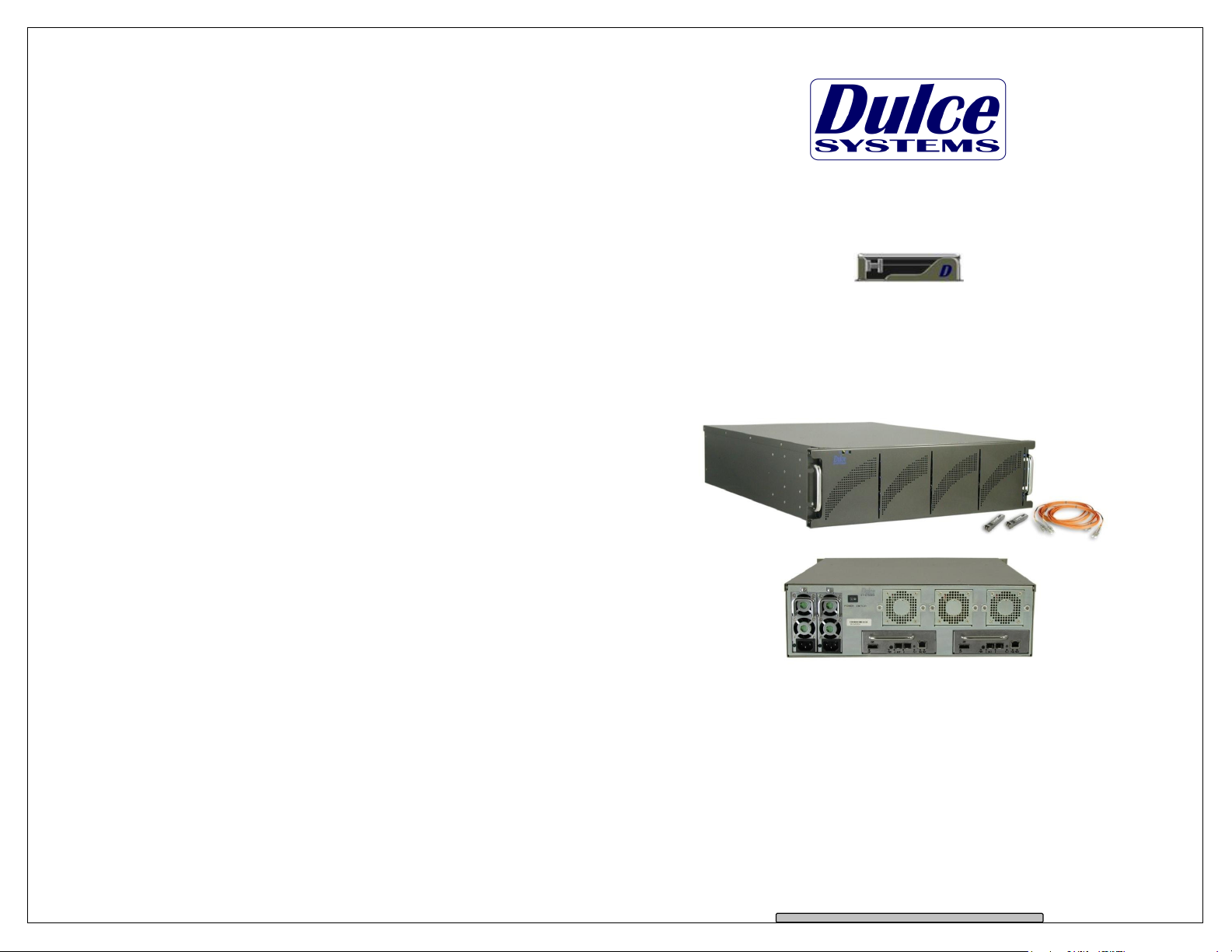
PRO IDC
with generation 2 drive trays
Installation and User’s Manual
Designed for Video Editing and Content Creation Professionals
Document 900-0018-0 v1.2
Page 2

PRO IDC Installation and User’s Manual
PRO IDC Installation and User’s Manual
Table of Content
1. Introduction ................................................................................................... 3
1.1. Safety Considerations ............................................................................. 4
1.1.1. SAFETY CONSIDERATIONS .......................................................... 4
1.1.2. CONSIDÉRATIONS DE SÉCURITÉ ................................................ 5
1.1.3. SAFTY BERÜCKSICHTIGUNGEN ................................................... 6
1.1.4. CONSIDERACIONES DE SEGURIDAD .......................................... 7
1.2. System Requirements ............................................................................. 8
1.3. Technical Support ................................................................................... 8
2. Getting Started .............................................................................................. 9
2.1. Packaging ............................................................................................... 9
2.2. Check List ............................................................................................... 9
3. Overview ..................................................................................................... 10
3.1. The Bezel .............................................................................................. 10
3.2. Disk Module .......................................................................................... 10
3.3. Front and rear views ............................................................................. 11
3.4. Independent Left and Right Controllers ................................................. 12
4. Installation ................................................................................................... 13
4.1. Rackmount Installation .......................................................................... 13
4.2. Disk Module Installation ........................................................................ 14
4.3. FC Cable Installation ............................................................................. 15
4.4. Drivers ................................................................................................... 15
4.5. Ethernet Configuration .......................................................................... 15
4.6. RAID Manager Installation .................................................................... 16
5. RAID Manager Operations .......................................................................... 17
5.1. Start RAID Manager .............................................................................. 17
5.2. Connect RAID Manger to PRO IDC ...................................................... 17
5.2.1. PRO IDC Discovery ........................................................................ 17
5.2.2. Login ............................................................................................... 18
5.3. RAID System Information ...................................................................... 19
5.4. RAID Creation ....................................................................................... 20
5.5. RAID Deletion ....................................................................................... 23
5.6. Create >2TB RAID Set for Windows XP (32bit) .................................... 25
6. Alarm Conditions / Degraded RAID Set ...................................................... 26
6.1. Replacing a Disk Module ...................................................................... 27
7. Formatting and Partitioning ......................................................................... 28
7.1. Apple OS X Formatting ......................................................................... 28
7.1.1. Erase an existing partition .............................................................. 28
7.1.2. Create a new partition..................................................................... 29
7.2. Windows XP / Vista Formatting ............................................................. 30
8. RAID Level Descriptions ............................................................................. 32
9. Limited Warranty ......................................................................................... 33
10. Product Registration ................................................................................. 34
1. Introduction
We appreciate your purchase of this product from Dulce Systems. You have
everything you need to quickly and easily connect the storage unit to your editing
computer or shared storage network. You are a short time way from your next
blockbuster creation.
This Installation and User’s Manual is intended to streamline the process of
getting your RAID storage system up and running so you can get to work quickly.
For most typical video editing storage requirements, we have preconfigured the
PRO IDC for a much more streamlined installation. Refer to the Preconfiguration Sheet for the exact pre-configuration of your PRO IDC, the default
configured is for RAID 5 (efficient protection mode) and pre-formatted for Mac
OS X. Just simply follow the installation steps outlined in this manual, and you
will up and running in no time. For Windows operation, a short format process
will be required.
Page 2
Page 3
Page 3
PRO IDC Installation and User’s Manual
RISK OF ELECTRIC SHOCK
DO NOT OPEN
PRO IDC Installation and User’s Manual
RISQUE DE DÉCHARGE ÉLECTRIQUE
N'OUVRIR PAS
1.1. Safety Considerations
1.1.1. SAFETY CONSIDERATIONS
W A R N I N G
WATER AND MOISTURE
To reduce the risk of fire or electrical shock, do not expose unit to rain or
moisture. Do not operate unit near water – such as: bathtub, washbowl, kitchen
sink or laundry tub, wet basement, or near a swimming pool.
STABILITY
Do not place this unit on an unstable cart, stand, bracket, or table. Unit may fall,
causing serious injury.
VENTILATION
Do not block front and rear ventilation. Proper airflow is required to ensure
reliable operation and prevents unit from over heating. Do not place unit in an
enclosed space where no or insufficient ventilation is available.
ELECTRICAL
Do not defeat the safety purpose of the grounding power plug. The power cord
should be routed so that it is not likely to be walked on or pinched by items
placed upon or against them.
SERVICING
Do not attempt to service this unit yourself. Opening or removing the top, side
and rear covers will expose you to dangerous voltages or other hazards.
1.1.2. CONSIDÉRATIONS DE SÉCURITÉ
AVERTISSEMENT
EAU ET HUMIDITÉ
Pour réduire le risque de feu ou de choc électrique, n'exposez pas d'unité pour
pleuvoir ou l'humidité. Ne faites pas marcher d'unité près de l'eau – comme; la
baignoire, la cuvette, l'évier ou la cuve de blanchisserie, la cave mouillée ou près
d'une piscine.
STABILITÉ
Ne placez pas cette unité sur un chariot instable, un éventaire, une parenthèse
ou une table. L'unité peut tomber, en provoquant la blessure sérieuse.
VENTILATION
Ne bloquez pas de devant et élevez la ventilation. L'écoulement d'air nécessaire
est tenu de garantir l'opération sûre et prévient l'unité de sur le chauffage. L'unité
ne peut pas placé dans un espace fermé où aucune ventilation ou dans suffisant
n'est disponible.
ÉLECTRIQUE
Ne vainquez pas le but de sécurité de la prise de courant de pouvoir de bases.
La corde de pouvoir devrait être mise en déroute pour qu'ils ne seront pas
probablement marchés sur ou pincés par les articles placés sur ou contre eux.
ENTRETIEN
N'essayez pas d'assurer l'entretien de cette unité vous-même. En s'ouvrant ou le
fait d'enlever le haut, le côté et les couvertures arrière vous exposeront aux
voltages dangereux ou à d'autres hasards.
Page 4
Page 5
Page 4
PRO IDC Installation and User’s Manual
NICHT ÖFFNEN
PRO IDC Installation and User’s Manual
GEFAHR DES STROMSC
HLAGS
NICHT ÖFFNEN
1.1.3. SAFTY BERÜCKSICHTIGUNGEN
W A R N U N G
ELEKTROSCHOCKGEFAHR
WASSER UND FEUCHTIGKEIT
Um eine Brand- oder Elektroschockgefahr weitgehend auszuschließen, Gerät
nicht Regen oder Feuchtigkeit aussetzen. Gerät nicht in der Nähe von Badeoder Waschwannen, Wasch- oder Spülbecken, feuchten Kellern oder
Schwimmbecken betreiben.
STABILITÄT
Das Gerät nicht auf wacklige Karren, Ständer, Halterungen oder Tische stellen,
da es herunterfallen und Verletzungen verursachen könnte.
BELÜFTUNG
Vordere und hintere Belüftungsöffnungen nicht versperren. Das Gerät muss
ausreichend be- und entlüftet werden können, damit es sich nicht während des
Betriebs überhitzt. Daher darf das Gerät nicht in geschlossenen Räumen
aufgestellt werden, in denen keine ausreichende Be- und Entlüftung
gewährleistet ist.
STROMVERSORGUNG
Nicht den Schukostecker modifizieren. Das Stromkabel sollte so verlegt werden,
dass es nicht durch Auftreten oder durch spitze oder scharfe Gegenstände
beschädigt werden kann.
WARTUNG
Das Gerät nicht eigenmächtig warten. Durch das Öffnen des Geräts (Abziehen
der oberen, seitlichen und hinteren Abdeckung) setzen Sie sich
lebensgefährlichen Spannungen aus.
1.1.4. CONSIDERACIONES DE SEGURIDAD
ADVERTENCIA
AGUA Y HUMEDAD
Para reducir el riesgo de fuego o electrochoque, no exponga la unidad para
llover o humedad. No haga funcionar la unidad cerca del agua – como; bañera,
lavatorio, fregadero o tina de lavandería, sótano mojado o cerca de una piscina.
ESTABILIDAD
No coloque esta unidad en un carro inestable, soporte, soporte o mesa. La
unidad puede caerse, causando la herida seria.
VENTILACIÓN
No bloquee delantero y críe la ventilación. El corriente de aire apropiado es
requerido asegurar la operación confiable y previene la unidad de sobre la
calefacción. La unidad no puede colocado en un espacio incluido donde ninguna
ventilación o en suficiente está disponible.
ELÉCTRICO
No derrote el objetivo de seguridad del enchufe de poder que da buenos
conocimientos. La cuerda de poder debería ser derrotada de modo que ellos
probablemente no sean andados en o pellizcados por artículos colocados sobre
o contra ellos.
REVISIÓN
No intente atender esta unidad usted mismo. Abriéndose o quitar la cumbre, el
lado y las tapas traseras le expondrán a voltajes peligrosos u otros riesgos.
Page 6
Page 7
Page 5
PRO IDC Installation and User’s Manual
System Requirements
Server
Mac OS X 10.4 or higher.
Mac Pro
2 or 4Gb Fibre Channel Port with optical LC connection.
Technical Support
If the product requires service, please contact Dulce Systems’ Technical Support
and obtain an RMA number. Ship the product properly packaged to:
620
Chatsworth, CA 91311
PRO IDC Installation and User’s Manual
1.2.
•
Windows XP / Vista /
•
•
Linux / Unix.
•
Apple Power Mac G5,
•
1.3.
Phone
FAX
E-mail
Web
/ 32 & 64-bit.
, Windows compatible PC.
818-435-6007
818-576-0324
www.dulcesystems.com
Dulce Systems
Attn: RMA
9
Topanga Canyon Place,
Suite E
2. Getting Started
The PRO IDC comes pre-assembled and almost ready for use, just install the
Disk Modules, attach the Fibre Channels to the computer or the switch, and
install the JAVA RAID Manager. If you are using a Mac, you are good to go, by
default the unit is pre-formatted for Mac OS X operation. For Windows, a small
format procedure is needed.
2.1. Packaging
Please do not discard the boxes and packing materials in case you
might need to reuse them later. Always ship the product in its original
packaging. Improperly packaged products will be subjected to shipping
damage, for which you will be liable for the repair.
2.2. Check List
• Installation and User’s Manual.
• Power Cords (North America user only).
• 3u 19” rackmount 16 disk bay system enclosure.
• 16 Disk Modules.
• One Ethernet Cable.
• 2 One 3-meter LC to LC optical Fibre Channel cable.
• 2 SFP Optical Transceiver.
• Rackmount rails (optional)
Page 8
Page 9
Page 6
PRO IDC Installation and User’s Manual
removal.
PRO IDC Installation and User’s Manual
Port
3. Overview
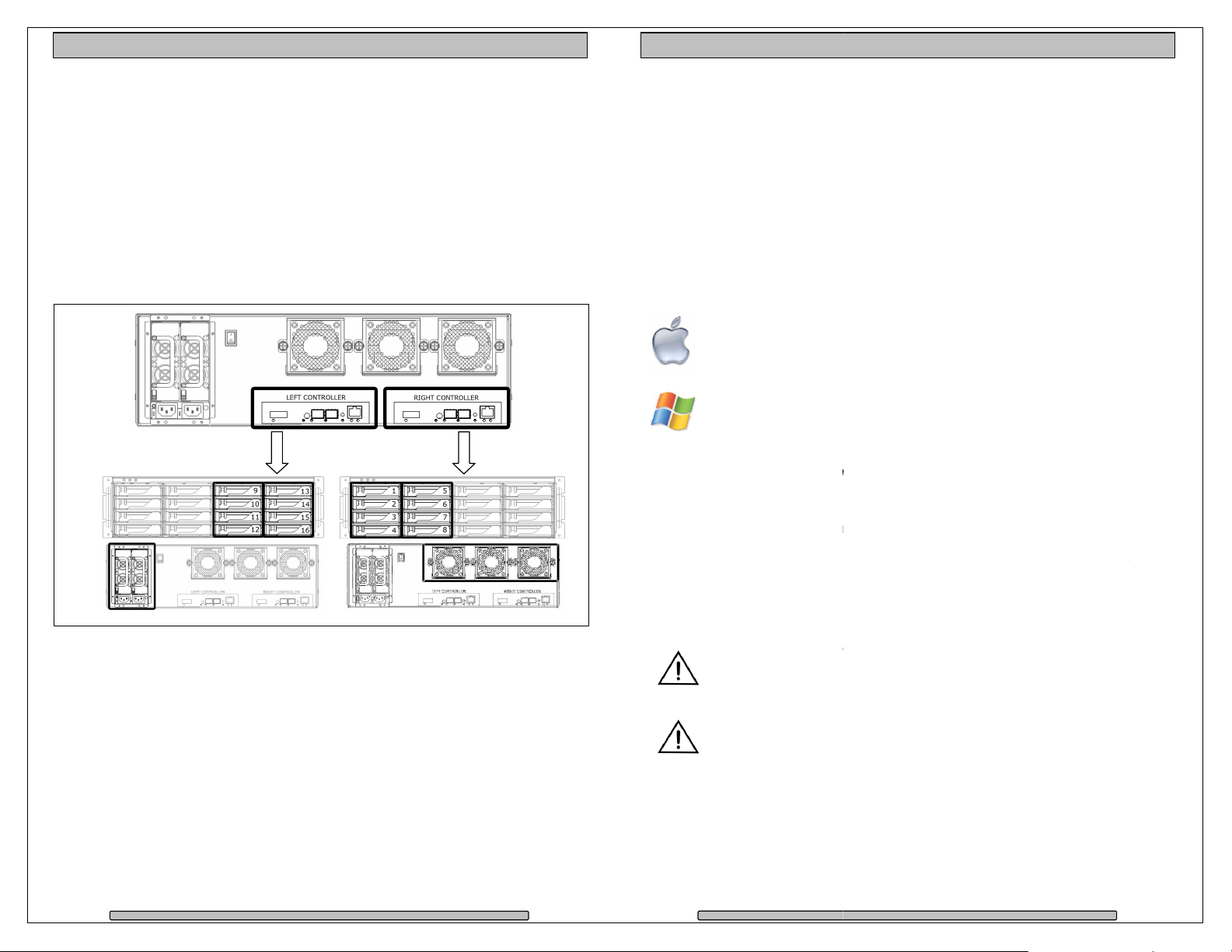
The PRO IDC consists of two independent RAID controllers, each controller
manages 8 disk drives. Each controller operates independent of each other and
each are seen as separate individual LUNs to the operating system.
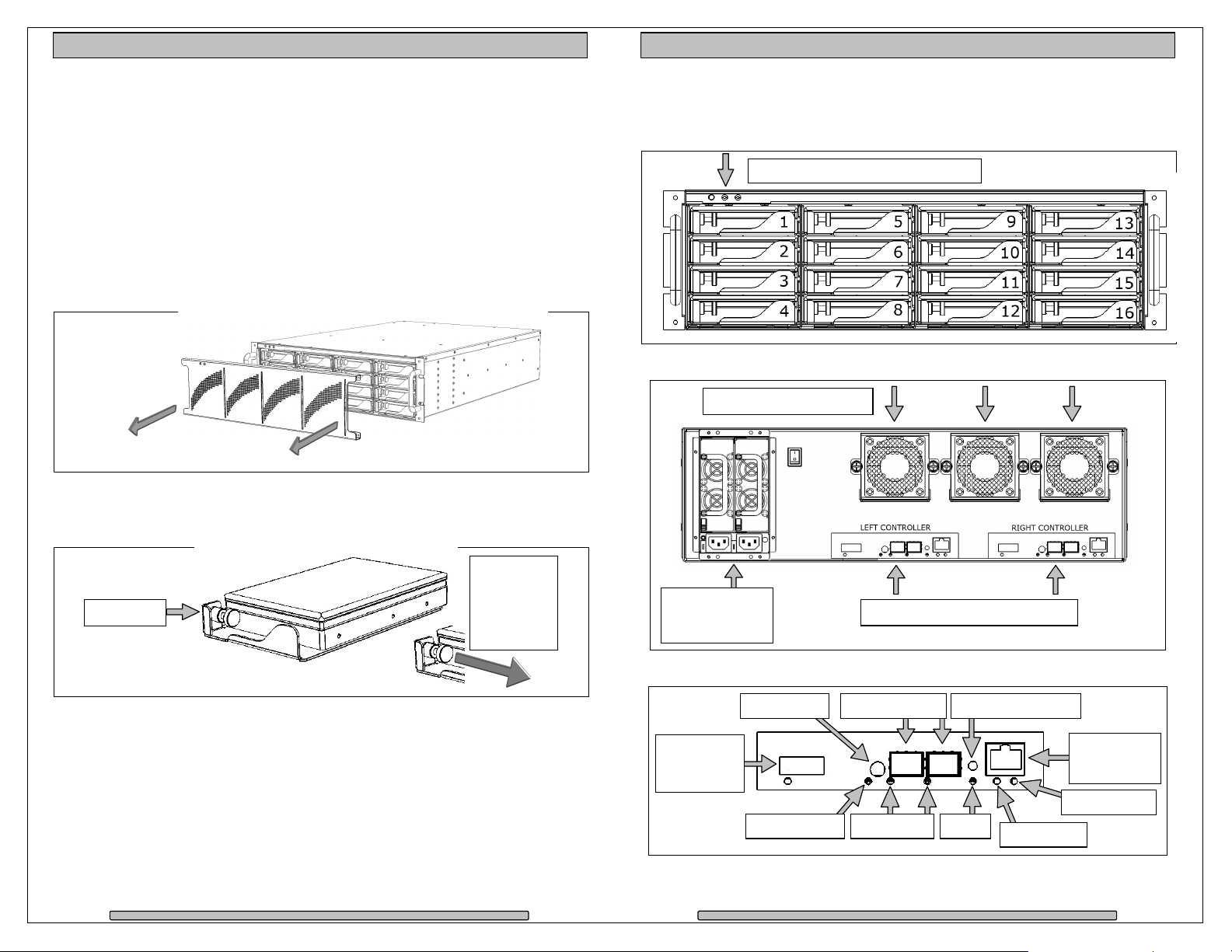
3.1. The Bezel
The front bezel can be easily removed to access the Disk Modules. The bezel is
held on by four snap pins located at each of the four corners.
Use both hands, push from behind the left and right side of the bezel. Access
through the rack mount handles.
3.2. Disk Module
Disk Module
3.3. Front and rear views
Front view
Mute Button, Fan Alarm, Temp Alarm
Rear view
Removable Cooling Fans
Lock Pin
Page 10
Pull right
to unlock
during
insert and
Redundant Hot
Swappable
Power Supplies.
Removable RAID Controllers
RAID Controller
Serial Port Alarm Reset / Mute
Enclosure
Expander
Port
Power Status FC Activity
FC Ports A & B
Fault
Ethernet
Management
Ready Status
Disk Activity
Page 11
Page 7
PRO IDC Installation and User’s Manual
Please follow these few steps to install the
minutes to complete.
Installation
PRO IDC
formatted for Apple Mac OS X.
Sheet for your exact configuration.
Windows operation will
already pre
Windows Disk Management utility to prepare the RAID for Windows
Rackmount Installation
can be rackmounted to a standard 19”
An optional rackmount kit is available for 24”
Mount the left and right rails to the rack, ensure sufficient 3u space is available.
t and right sliders on the
loaded with Disk Modules will be
to the rack before installing the drives will make it easier.
carefully on the rack by aligning the sliders in the rails.
Front heavy topple warning
extended position when mounted on the rack, your
entire rack might tip over and will cause se
Page
PRO IDC Installation and User’s Manual
his process typically
mode
configuration
PRO
imply run the
rack. 3u height space is
heavy, install the
Install
– Do not operate or configure the PRO
and harm
3.4. Independent Left and Right Controllers
Each controller is independent of each other. Each controller manages its own
set of eight drives. One controller does not have access to the other controller’s
disk drives.
The Right Controller manages drives 1 to 8 and also monitors the Cooling Fans
status.
The Left Controller manages drives 9 to 16 and also monitors the Power Supply
status.
4. Installation
takes about 30
Overview of installation:
•
Rackmount installation
•
Disk Module Installation
•
FC Cables Installation
•
Ethernet Configuration
•
RAID Manager
By default, the
and pre-
IDC is shipped
usage.
4.1.
The PRO IDC
required.
Adjust depth as required.
Mount the lef
The PRO IDC
IDC
the PRO IDC
PRO IDC. T
is shipped pre-configured in RAID 5
Check the Pre-
require a format/partition process. The
-configured in RAID 5. S
to 30” depths.
PRO IDC.
PRO
Page 12
IDC in the rack
vere damage
.
13
Page 8
PRO IDC Installation and User’s Manual
Rail mounted
Slider
PRO IDC Installation and User’s Manual
to rack.
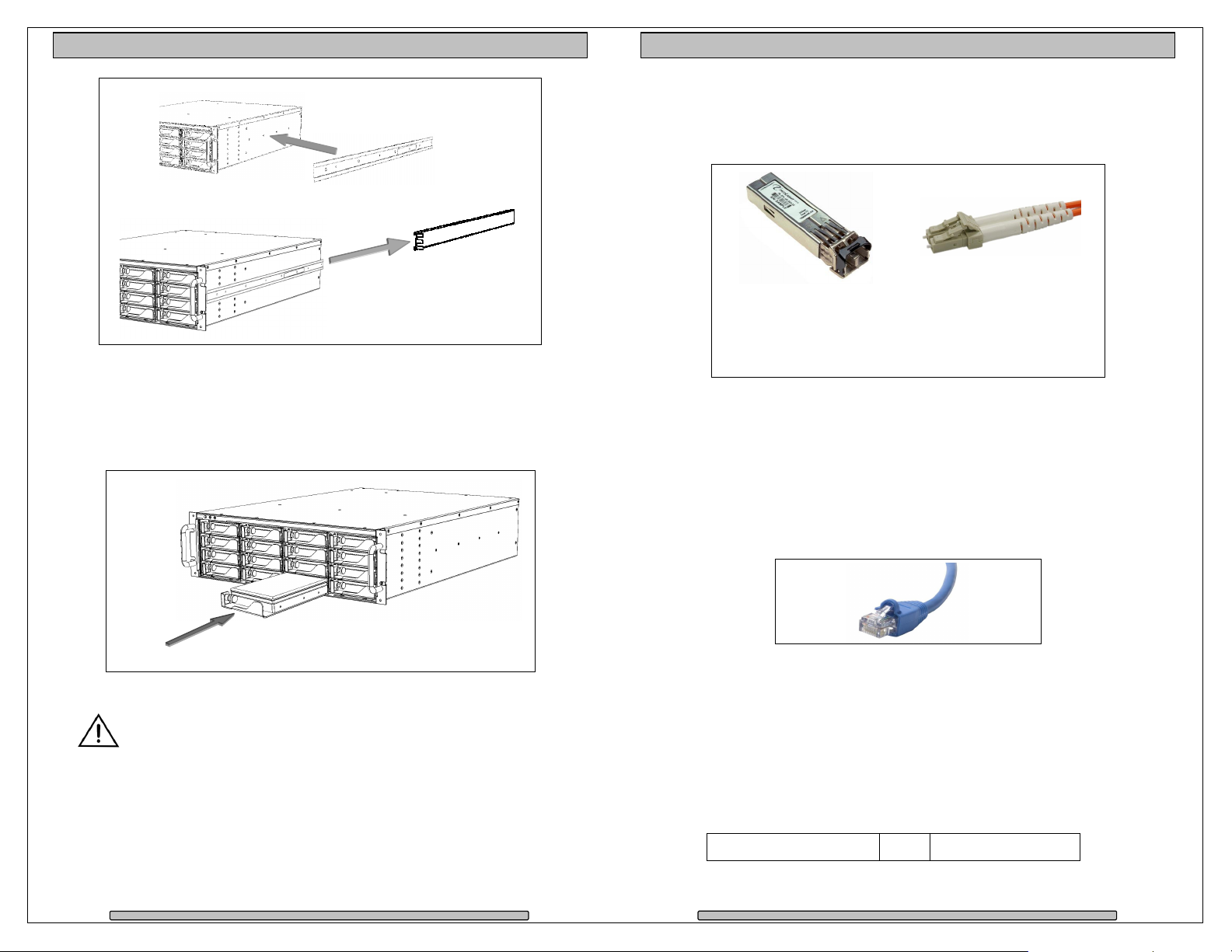
4.2. Disk Module Installation
Remove the front bezel. Install each marked Disk Module into the slot indicated.
Pull the Lock Pin to the right and insert drive tray fully, release Lock Pin to
secure.
4.3. FC Cable Installation
Install a SFP into one of the FC port of each controller from the rear of the PRO
IDC. Install the LC to LC optical Fibre Channel Cables.
SFP Remove the
protective covering.
Insert into FC port
label up.
LC to LC cable Remove the protective
tip covering. Insert into
SFP.
4.4. Drivers
Drivers are not needed to operate the PRO IDC. But the Fibre Channel adapter
the PRO IDC connects to will need drivers, please refer to the requirements of
the adapter.
4.5. Ethernet Configuration
The PRO IDC uses the built-in Ethernet ports for RAID management, both
controllers must be connected to your existing network for configuration.
DO NOT ship the PRO IDC with the Disk Modules installed, the Disk
Modules MUST be packaged separately in a single or multi-pack to
properly protect them during shipment.
Page 14
Network supporting HDCP for automatic IP Address assignments: Connect both
controllers to your network. The PRO IDC will automatically request from the
network the necessary IP addresses.
Network without DHCP: Defaults to the static IP address below. Working with
one controller first, leaving the other disconnected. Manually connect to the
controller and change to the desired static IP address with RAID Manager. RAID
Manager > Administration > IP Connection. Connect the 2nd controller and
repeat.
Auto Assign (DHCP) or 169.254.32.10
Page 15
Page 9
PRO IDC Installation and User’s Manual
RAID Manager
based RAID Manager to confi
Use the supplied installation CD or
Start the install program from the Downloads folder on the dock
load completes.
Save the install.exe on the desktop then run it after
download is complete.
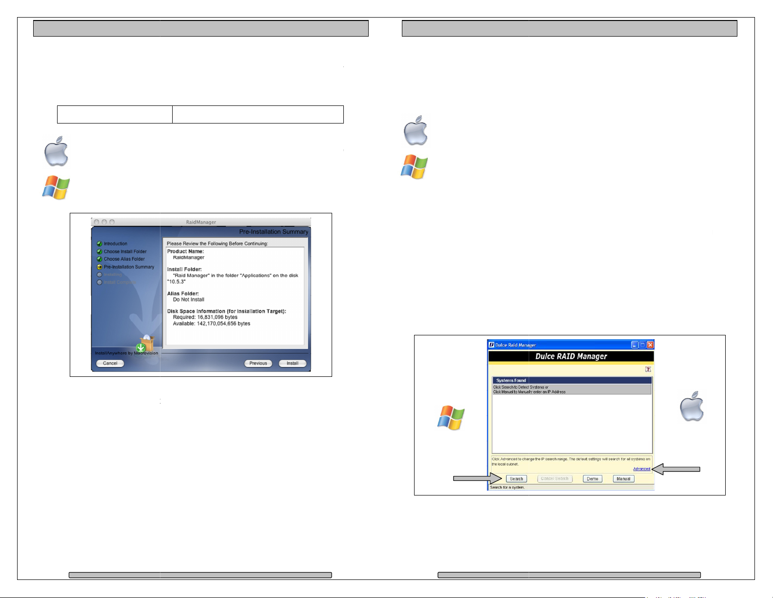
Mac screen shot shown. Windows will be similar.
Follow the on screen prompts to complete the installation. See next sect
RAID Manager operational instructions.
gure and manage the
visit our web site and download the
ion for
Operations
Manager
Start the RAID Manger from the RAID Manger folder.
older
All Programs menu > RAID Manger folder
RAID Manger to
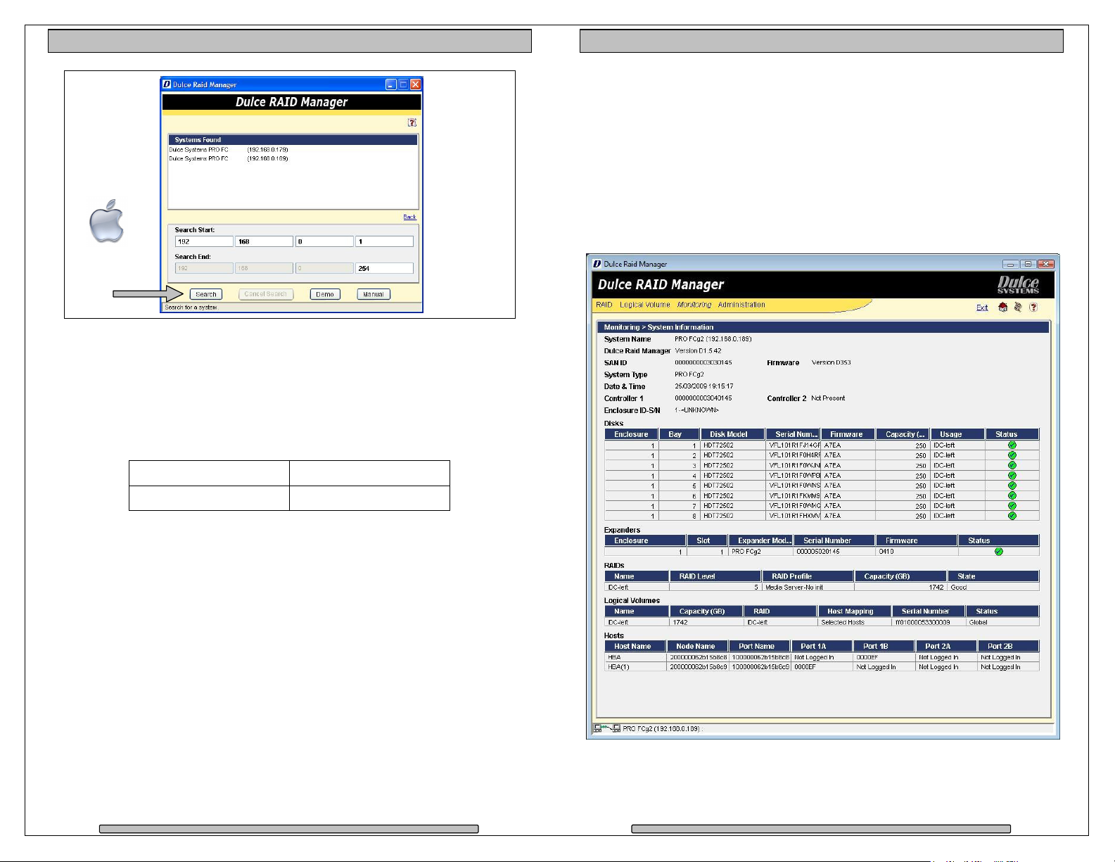
Discovery
RAID Manager needs to know the IP Address of the
Discovery will show two PRO FCs that makes up
Mac users should use the Advanced method due to the security nature of the
Mac operating system. Windows and Mac users with root user access can use
Page
PRO IDC Installation and User’s Manual
, use the Search
method to auto discover or use Manual if you
Advanced
4.6.
The PRO IDC uses a Java
RAID.
RAID Manager Installer.
Download From:
Apple:
after down
Windows:
Installation
www.dulcesystems.com/download
.
5. RAID Manager
5.1. Start RAID
Apple: Applications f
(Windows) or Advanced (Mac)
know the IP Address.
Search.
Windows:
5.2. Connect
5.2.1. PRO IDC
> RAID Manager folder
PRO IDC
PRO IDC
the PRO IDC.
Page 16
Mac use
Windows
use Search
option.
option.
17
Page 10
PRO IDC Installation and User’s Manual
Mac user
PRO IDC Installation and User’s Manual
(cont).
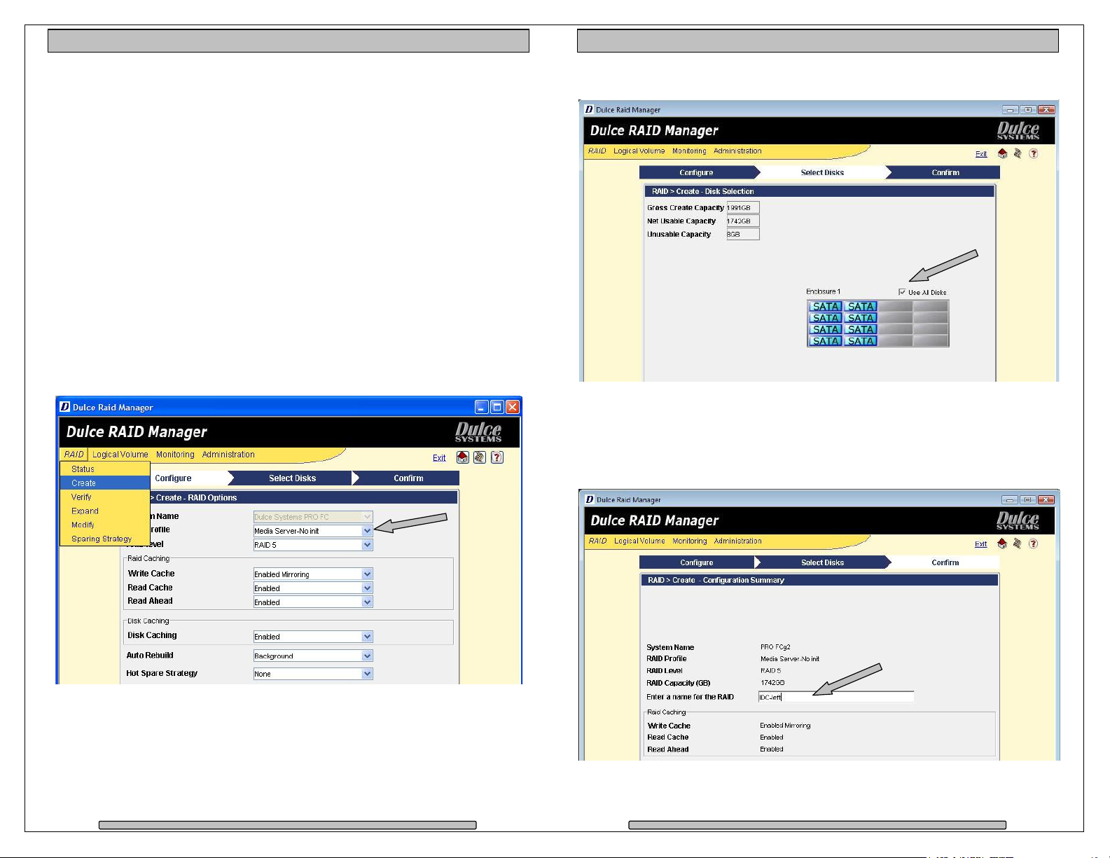
5.3. RAID System Information
The System Information screen (under the Monitoring menu) provides a quick
overview of the PRO IDC configuration. The PRO IDC has two independent
RAID controllers. Each half is configured and managed separately.
The System Information shows the status and configuration of the physical drives
connected, the RAID setup and the Volumes assigned under each RAID.
This screen shot is of the left controller, showing disks 1 to 8 of which it
manages.
Advanced / Search method could take up to 5 minutes to cover the entire search
range. This operation is only needed to be performed once, after discovery the
RAID Manager will remember the IP Address.
5.2.2. Login
The Systems Found list will show the discovered PRO IDCs. Double click on an
entry to start the login.
Username: admin
Password: admin
Page 18
Page 19
Page 11
PRO IDC Installation and User’s Manual
5.4. RAID Creation
PRO IDC Installation and User’s Manual
A new PRO IDC is normally pre-configured and formatted, you might not need to
go through this process, check the Pre-Configuration sheet that came with the
PRO IDC for details.
There are two independent RAID controllers in the PRO IDC, each half is
managed separately.
If you are changing the RAID configuration, you will need to 1st delete the RAID
then create a new RAID, see the Delete RAID section in this manual.
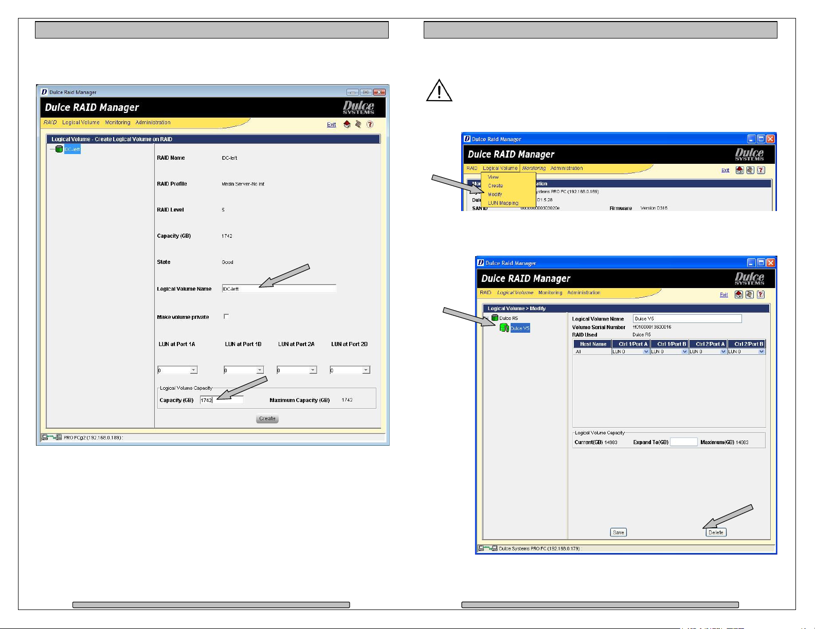
Creating a RAID set is easy; 1st create a RAID set of your choice with the disk
drives attached. 2nd create a Logical Volume under the new RAID set.
Click on the RAID menu and select Create. Select your desired options and click
Next. A number of preset RAID Profiles are provided.
The Media Server – No Init profile will give you instant RAID availability, no need
to wait for long RAID format.
Check the Use All Disks or individually select each disk for the RAID.
Enter a name for the RAID and Logical Volume, they are only used within RAID
Manager, this is not a name you will see in your operating system.
You can use ‘IDC-Left’ or ‘IDC-Right’ to better describe the two for the RAID and
Volume names.
Page 20
Page 21
Page 12
PRO IDC Installation and User’s Manual
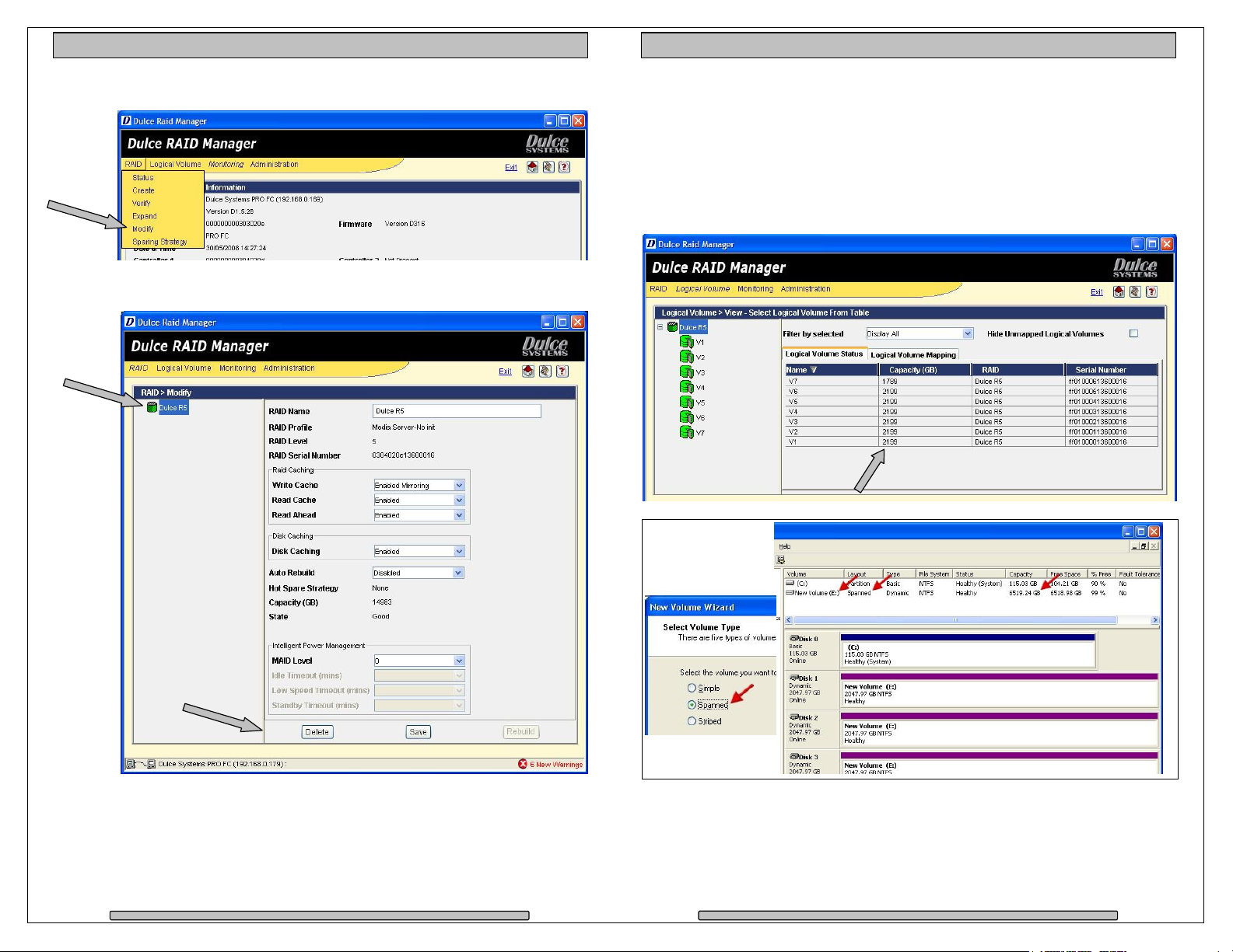
Enter the desired Capacity (always the maximum) for the Logical Volume, then
PRO IDC Installation and User’s Manual
lastly click on Create.
5.5. RAID Deletion
Deleting a Logical Volume and RAID will destroy all data.
1st: Delete the Logical Volume, from the Logical Volume menu select Modify.
Attach the two controllers to your computer or switch. You would see the PRO
IDC as two available disks in the format utility of your operating system.
On left side, expand the RAID to expose the Logical Volume under it. Click on
the Logical Volume to select it, click on Delete.
Page 22
Page 23
Page 13
PRO IDC Installation and User’s Manual
2nd: Delete the RAID, from the RAID menu select Modify.
PRO IDC Installation and User’s Manual
5.6. Create >2TB RAID Set for Windows XP (32bit)
This only applies to Windows XP (32 bit) where it has a 2TB disk size limitation.
Create a RAID of your choice with the number of desired disk drives, then create
multiple Logical Volumes of 2TB size. This will present to Windows XP as
several disks of 2TB sizes. Use Windows Disk Manager to Span them together
(not Stripe) to create one drive letter of the sum of all the <=2TB sized disks.
On the left side, click on the RAID to select it, then Delete.
Page 24
Page 25
Page 14
PRO IDC Installation and User’s Manual
PRO IDC Installation and User’s Manual
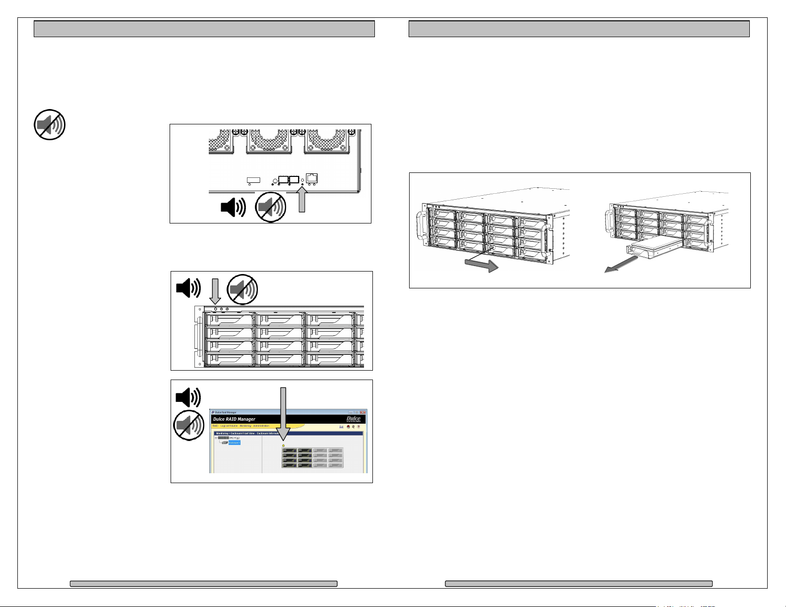
6. Alarm Conditions / Degraded RAID Set
There are several possible sources for alarms, the front and rear indicators and
the RAID Management will provide the details of the alarm.
Mute Alarm:
1) Alarm Reset button in
the rear of unit.
Controller Alarm
confirmed with a red
ALT indicator.
• Temperature
(enclosure detected over heating condition)
• Fan (enclosure cooling fan not operational, could lead to overheating)
• RAID related problem such as a failed disk drive.
2) Reset button at the top
front left of unit.
3) RAID Manager GUI.
RAID Alarm
• Degraded RAID Set
(one or more drives not
detected or down)
• Temperature (RAID
Controller detected
over heating)
RAID Manager > Monitoring > Enclosure Front/Back View. Double click on the
yellow bell.
The Event Viewer screen provides a log of events which triggered the alarm. To
view it, from the Monitoring menu, click on Event Viewer.
6.1. Replacing a Disk Module
A defective Disk Module can be easily replaced. Hot swapping is allowed without
interruption to your workflow if the RAID is operating in one of the drive
redundant RAID mode (1,5,6).
In a redundant RAID mode, rebuild will start automatically after replacement of a
defective module.
• Pull the Lock Pin to the right and pull the Disk Module out.
The RAID rebuild will consume some processing power from the overall
operation speed of the PRO IDC, the rebuild can be suspended during time
sensitive operations.
From RAID Manager, click on RAID > Modify. Select the RAID on the left side,
then click on Stop Rebuild at the lower right.
The audible alarm will sound, follow the Alarm Condition / Mute Alarm to handle
it.
Page 26
Page 27
Page 15
PRO IDC Installation and User’s Manual
ng and Partitioning
Formatting
are shipped pre
appear on the desktop after driver installation and reboot.
Should it be necessary to re
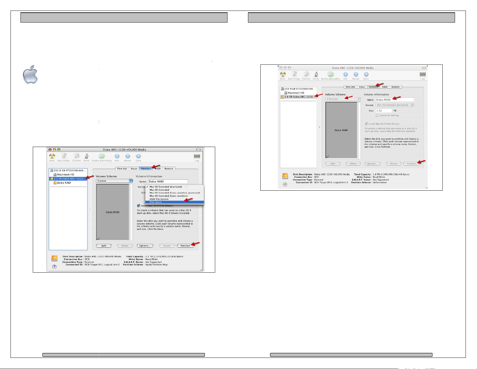
To start Disk Utility, move pointer to upper left corner of screen, click on Go then
ocate and launch Disk Utility.
existing partition
Select the RAID on left, click on Partition tab, select Free Space. Click on
configured for Mac OS X, the RAID will
PRO IDC Installation and User’s Manual
7. Formatti
7.1. Apple OS X
The PRO IDC
Apple Disk Utility.
click on Utilities. L
7.1.1. Erase an
Partition on lower right.
-
-format and partition the RAID, use the
7.1.2. Create a new partition
Select Dulce on the left side drive list, click on Partition tab, change Volume
Scheme to 1 Partition, change Name as desired, click on Partition on lower right.
The drive will appear on the desktop after successful completion of the Partition.
Page 28
Page 29
Page 16
PRO IDC Installation and User’s Manual
7.2. Windows XP / Vista Formatting
PRO IDC Installation and User’s Manual
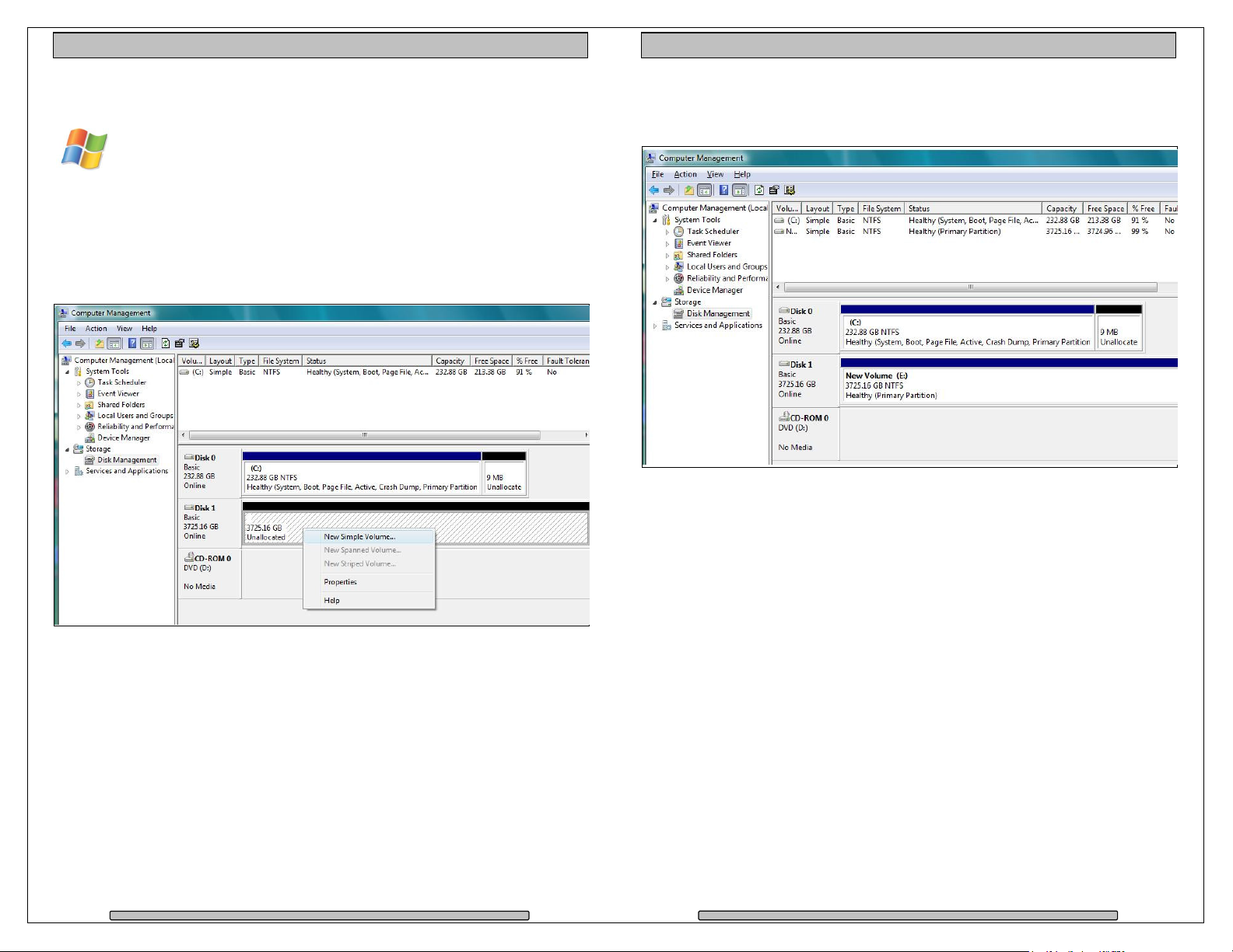
Start Disk Management (can be found at Control Panel > System and
Maintenance > Administrative Tools > Computer Management. Under
Storage.)
If the RAID shows up as Unknown / Not Initialized, right click on the disk and
Initialize it.
If the drive is larger than 2TB, if using Vista, right click over the disk and Convert
to GPT Disk. Windows XP 32 bit does not support larger than 2TB capacity.
Configure with multiple capacities of 2TB or less.
Right click the Unallocated segment and select New Simple Volume. Enter the
desired Volume Size, assign the desired Drive Letter or Path, check Perform a
Quick Format at the Format Partition screen.
Page 30
Page 31
Page 17
PRO IDC Installation and User’s Manual
PRO IDC Installation and User’s Manual
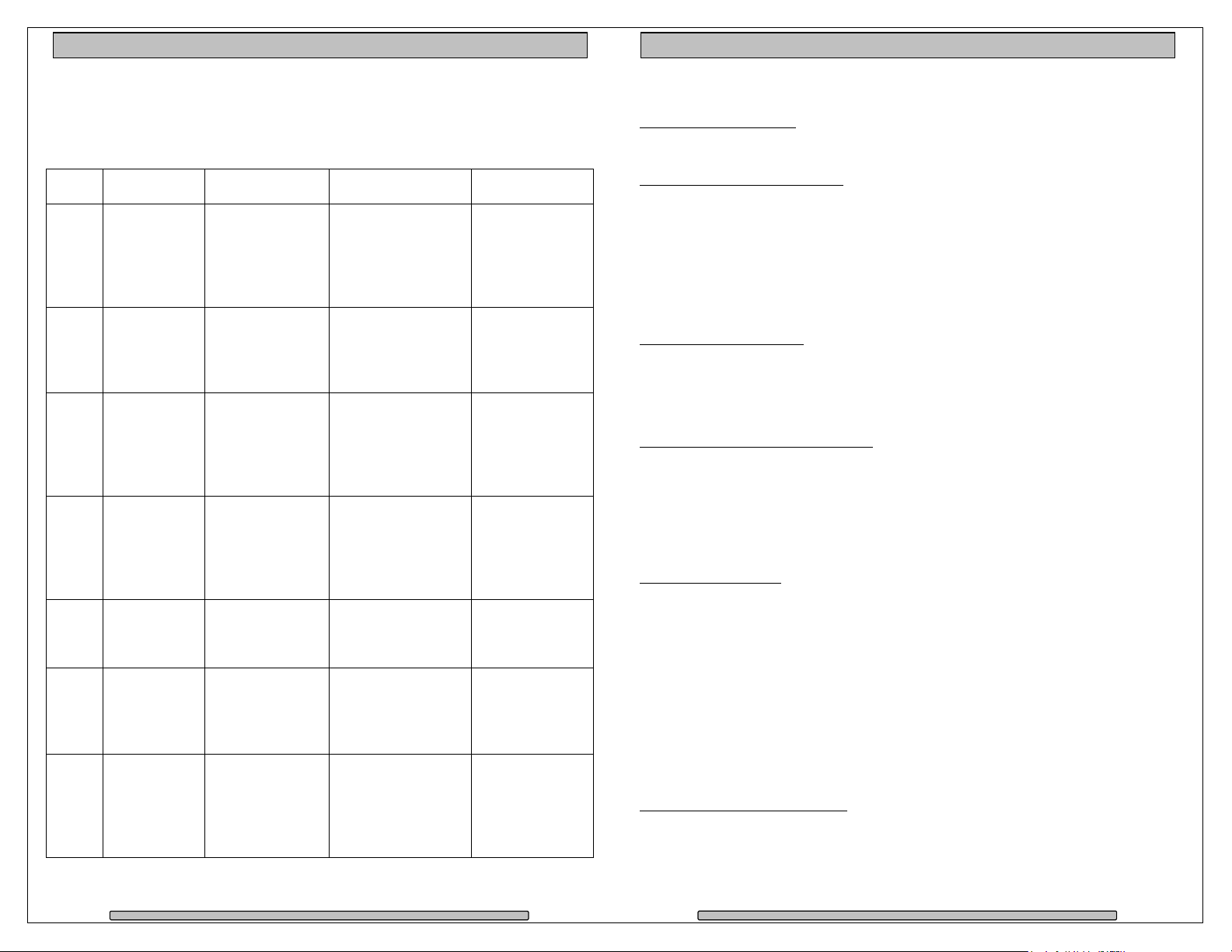
8. RAID Level Descriptions
Although the RAID Controller supports a large variety of RAID Levels, RAID 0 or
RAID 3 are most commonly used for video and content creation purpose.
RAID
Level
JBOD
RAID
Spare
Description Advantage Disadvantage Ideal for
No disk
0 Striping.
Highest
performance.
redundancy, one
drive failure will
lose all data.
Less cost efficient
1 Mirroring.
Highest
redundancy.
for redundancy,
loses ½ disk
capacity.
Efficient drive
redundancy, 1
drive used for
parity.
Efficient drive
redundancy,
parity distributed
to all drives.
Double drive
redundancy, 2
drives used for
parity.
Loses 1 disk drive
capacity.
Loses 1 disk drive
capacity.
Loses 2 disk drive
capacity.
3
5
6
Striping with
a dedicated
parity drive.
Striping the
parity across
all drives.
Striping with
two
dedicated
parity drives.
Each drive can
Just a Bunch
of disks.
be accessed
individually from
operating
No redundancy.
system.
Loses another
+
A drive is set
aside as an
online hot
spare.
Automatic
rebuild of a
failed drive.
drive capacity. (In
addition to the
drive(s) needed for
the RAID level
selected.)
Highest
resolution HD,
2K, and
maximum
multiple
streams.
Data protection
is paramount,
maximum disk
failure
protection.
Well balanced
for video
requiring
performance
and
redundancy.
Well balanced
for file server
requiring
performance
and
redundancy.
Mission critical.
Audio
applications.
Minimizes
degraded RAID
level exposure
time.
9. Limited Warranty
WHAT THE WARRANTY COVERS
Dulce Systems warrants your product against any defect in material and workmanship and conforms to Dulce published
specifications under normal use.
WHAT THE WARRANTY DOES NOT COVER
The warranty does not cover equipment which has been damaged due to accident, misuse, abuse, fire, flood, "Acts of
God," or other contingencies beyond our control; use of incorrect line voltages; improper or insufficient ventilation; failure
to follow operating instructions; or improper or unauthorized repair; improperly packaged for shipping; packaged in nonapproved shipping container; shipping damage.
The warranty is voided by removal or alteration of the product or parts identification labels.
Dulce has no liability for general, consequential, incidental or special damages. These include loss of recorded data, the
cost of recovery of lost data, lost profits and the cost of the installation or removal of any Products, the installation of
replacement Products, and any inspection, testing, or redesign caused by any defect or by the repair or replacement of
Products arising from a defect in any Product.
WHAT THE WARRANTY PERIOD IS
Dulce Systems warrants your PRO IDC product for 36 months and if the product is registered with Dulce within 30 days of
purchase, we will extend the warranty for another 6 months totaling 42 months. We warrant the Duo for 36 months. The
warranty period begins at the date of shipment to the original end user, company or organization.
Our warranty applies to repaired or replaced Products for the balance of the applicable period of the original warranty or
ninety days from the date of shipment of a repaired or replaced Product, whichever is longer.
WHAT WE WILL DO TO CORRECT THE PROBLEM
We may elect which remedy or combination of remedies to provide at our sole discretion. We shall have a reasonable
time after determining that a defective Product exists to repair or replace a defective Product. Our replacement Product
under its limited warranty will be manufactured from new or reconditioned parts.
Your exclusive remedy for any defective Product is limited to the repair or replacement of the defective Product.
We will return the repaired or replacement Product to you prepaid using the same method of shipping (ex: overnight,
ground, 2nd day, …) as was shipped to us. If a more expedited return shipping method is required, extra charges might
apply at our discretion.
HOW YOU CAN GET SERVICE
Contact our Technical Support to obtain a RMA (Return Materials Authorization) number. The model number, serial
number, and description of the problem will be required. A valid proof of purchase might be required to further validate the
Products warranty eligibility, the valid proof of purchase document must show the product model, serial number, purchase
date, and supplier name. If the valid proof of purchase is not available, the original manufacturing date of the product will
be used to determine the warranty period.
No returns will be accepted without a RMA number. We reserve the right to refuse the delivery of the return.
You shall bear all shipping, packing and insurance costs and all other costs, excluding parts and labor, necessary to
effectuate repair or replacement under this warranty.
All products returned to us must be shipped in the original packaging or Dulce approved packaging. If you do not have the
original packaging, call us to request packaging. A nominal fee will be charged for the requested packaging and for
shipment. Ship the RMA to us pre-paid.
Products that are improperly packaged for shipping; packaged in a non-approved shipping container; or incur shipping
damages are not covered under warranty.
HOW STATE LAW RELATES TO WARRANTY
In the United States, some states do not allow exclusion or limitation of incidental or consequential damages, so the
limitations above may not apply to you. This warranty gives you specific legal rights and you may also have other rights
which vary from state to state.
Page 32
Page 33
Page 18
PRO IDC Installation and User’s Manual
10. Product Registration
PRO IDC Installation and User’s Manual
R E G I S T E R N O W
ADDS 6 MONTHS
Register your product within 30 days of purchase
and extend your warranty by another 6 months.
1 minute = 6 months
It will take only one minute to register and you’ll get 6 months in return!
By registering your PRO IDC, the standard 36 months warranty will be extended
for another 6 months. That’s a total of 42 months (3 years and 6 months
warranty.) The longest warranty in the industry!
Please visit our web site and register online.
www.dulcesystems.com/register
A valid proof of purchase might be required to further validate the Products warranty eligibility, the
valid proof of purchase document must show the product model, serial number, purchase date,
and supplier name. If the valid proof of purchase is not available, the original manufacturing date
of the product will be used to determine the warranty period.
(Page left blank intentionally)
Page 34
Page 35
Page 19
PRO IDC Installation and User’s Manual
www.dulcesystems.com
Page 36
 Loading...