

Page 1
Page 2
CONTENTS:
SECTION I
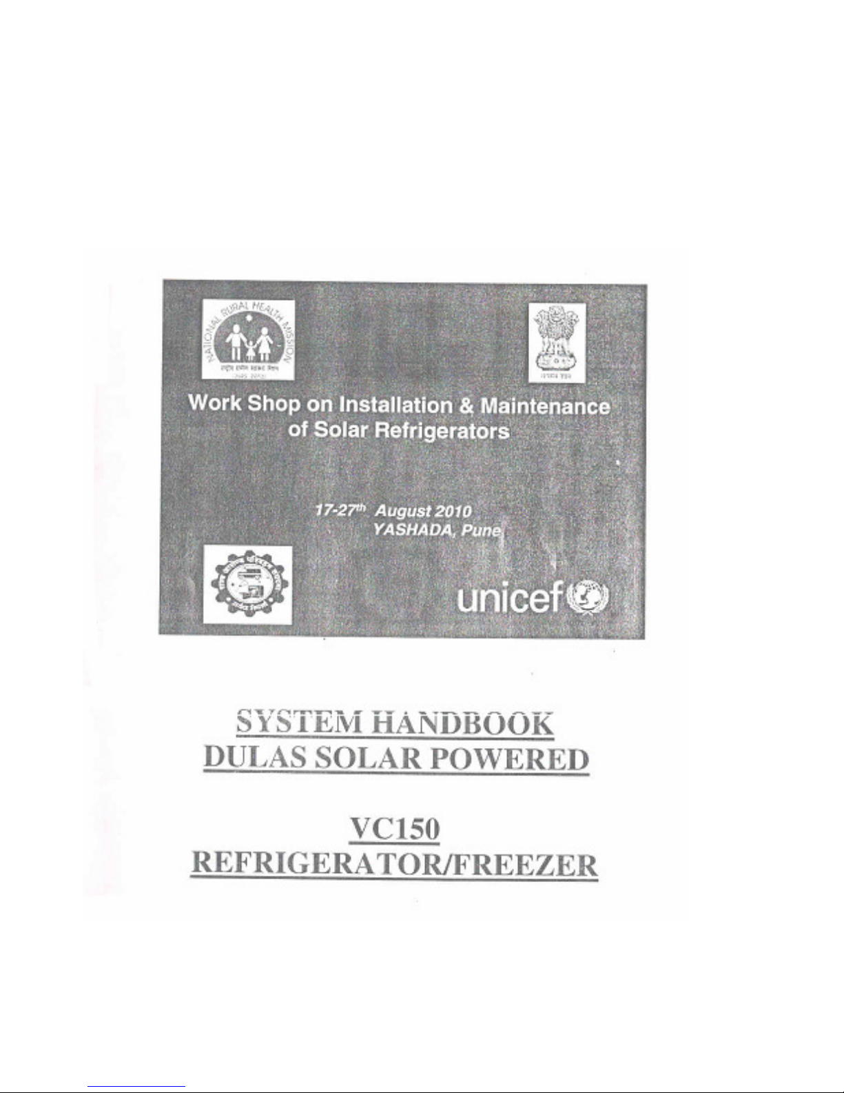
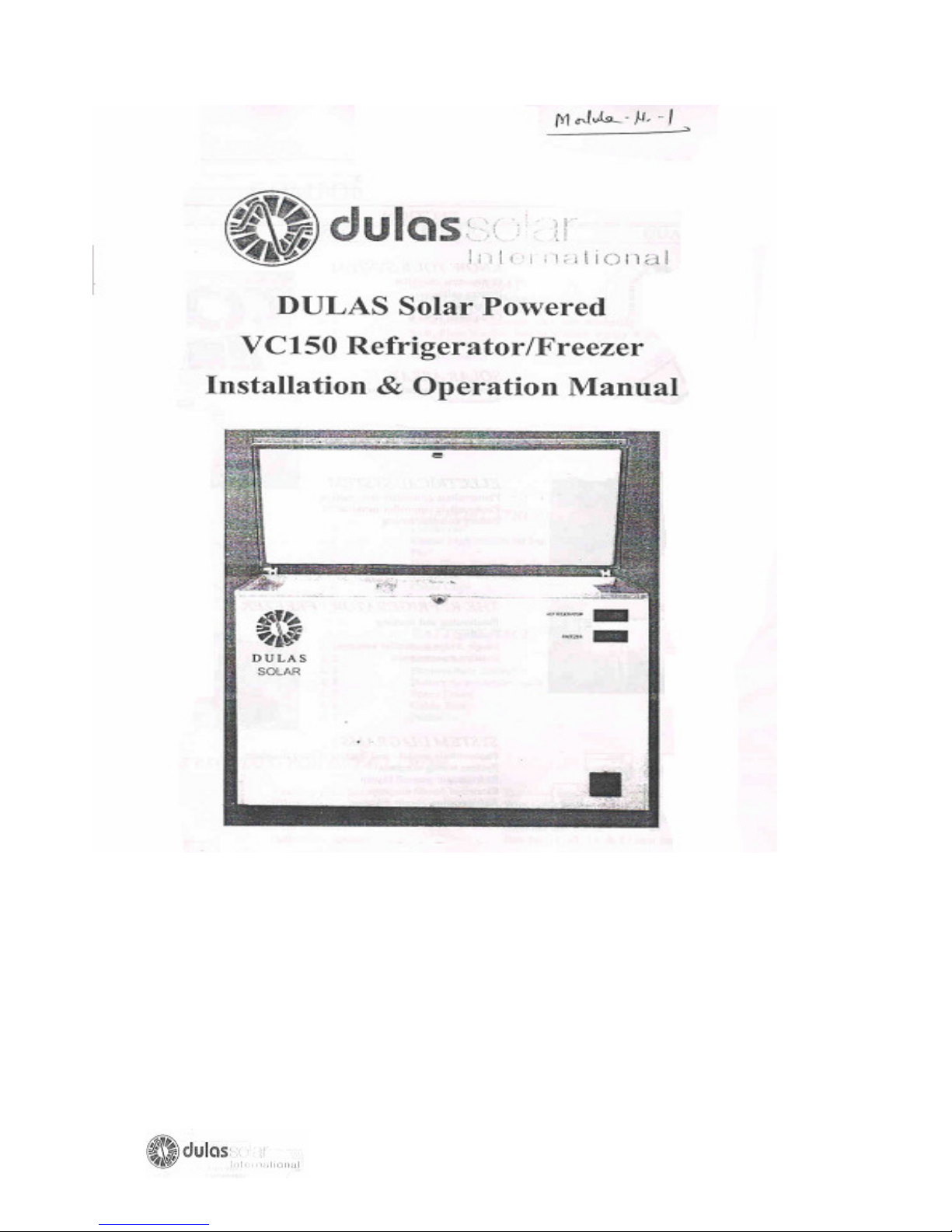
Dulas Solar Powered VC150 Refrigerator/Freezer
Installation & Operation Manual
………….
SECTION II
Fault Finding & Repair of
Photovoltaic Refrigerators
… ……
SECTION III
A User Handbook For
Photovoltaic Refrigerators…………… 1 to 23
Page
1 to 26
1 to 100
2
Page 3
SECTION I
3
Page 4
4
Page 5
CONTENTS
SECTION Page No.
KNOW YOUR SYSTEM
SOLAR ARRAY
ELECTRICAL SYSTEM
THE REFRIGERATOR/FREEZER
SYSTEM DIAGRAMS
Component checklist 3
Battery safety 4
Preparation 5
Completed system 6
Photovoltaic module assembly 7
Support structure orientation 8
Support structure assembly 10
Lightning protection 12
Photovoltaic controller information 13
Photovoltaic controller installation 14
Battery commissioning 15
Positioning and starting 1
Loading 21
Single fridge controller settings 22
Routine maintenance 23 & 24
Photovoltaic module and battery wiring 25
Diagrams
System wiring diagram 26
Refrigerator general layout 27
Electrical circuit diagram 28
Refrigeration circuit diagram 29
5
Page 6
COMPONENTS-CHECK LIST
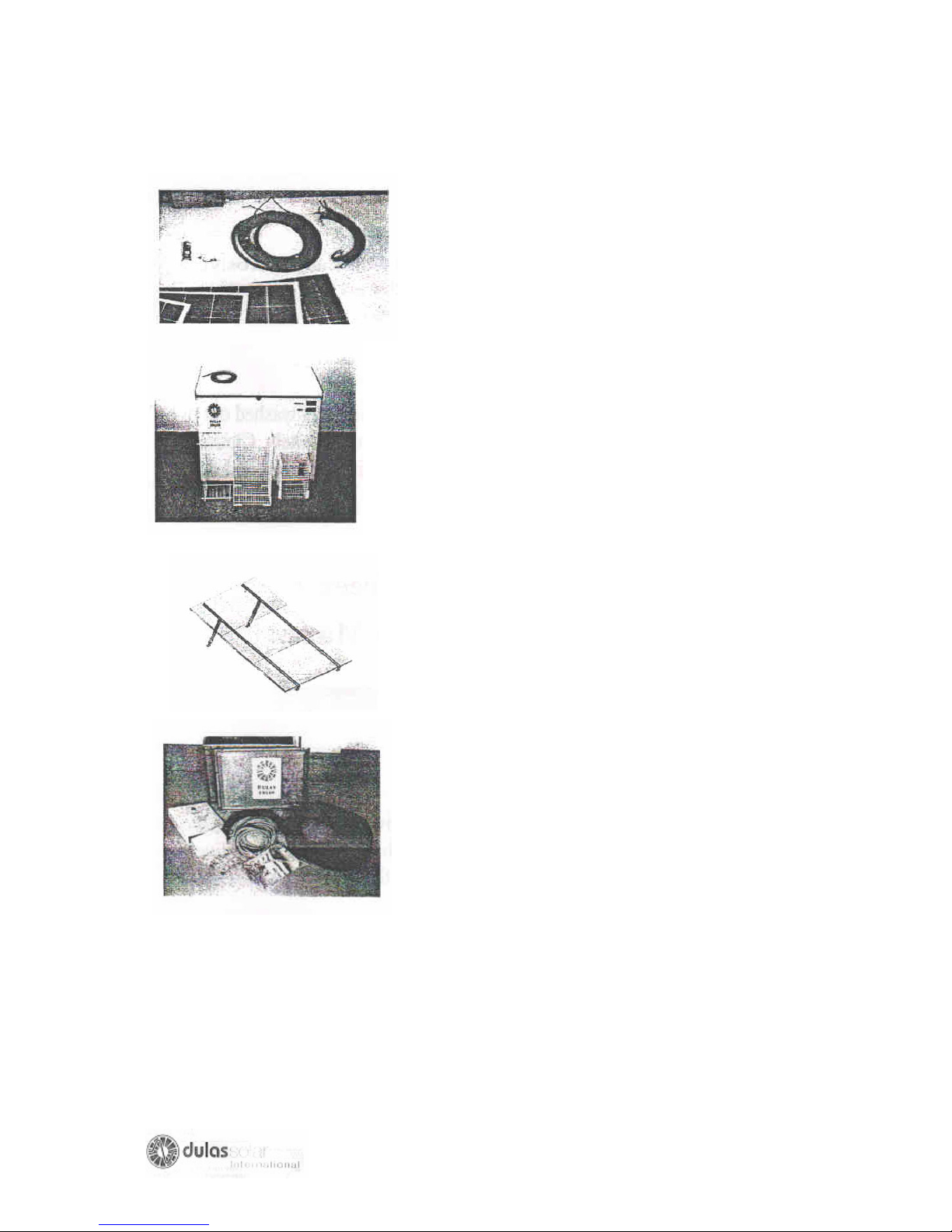
REF PRODUCT QUANTITY
SOLAR ARRAY
a.1 KD135 solar modules 2
a.2 10m array output cable 1
a.3 0.5m module
Interconnect cable assembly
1
a.4 Bolt, plain washer, Nylon washer,
Penny washer & Nut
a.5 Silicon Sealant 1
REFRIGERATOR
b.1 DULAS VC150 refrigerator/
Freezer
b.2 Refrigerator cable 1
SUPPORT STRUCTURE
Unirac rail
nut
c.1
c.2 Unirac high profile tilt leg kit 2
c.3 Feet 4
c.4 Bolt, plain washer, spring washer &
c.5 Screws & wall plugs Pack
c.6 Cable clips
BATTERY PACK
d.1 Battery 1
d.2 Battery box 1
d.3 Photovoltaic controller 1
d.4 Battery to controller cable 1
d.5 Spare fuses 3
d.6 Cable ties Pack
d.7 Padlocks 2
TOOLS REQUIRED FOR INSTALLATION
Pozidriv No.2 Screwdriver Slot-head Screwdriver
Pliers Wire Cutters
Wire Strippers Craft Knife
Drill and Bits Hammer & Punch
Adjustable Spanner Size10, 11, 13, 14 & 17mm Spanners
Pack
1
Pack
6
Page 7
BATTERY SAFETY
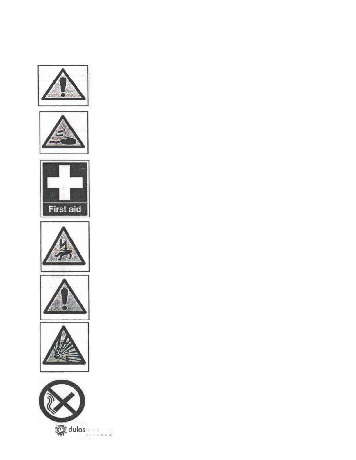
Observe operating instructions and position them within
sight of battery! Work only on batteries under instruction of skilled personnel!
The electrolyte (diluted sulphuric acid) is extremely corrosive. When
working on batteries wear safety glasses and protective clothing.
Acid splashes in the eyes or on the skin must be washed out or off with
plenty of water. Then see a doctor immediately. Clothing exposed to
acid should be washed out with water without delay.
Electrical danger! In the case of short circuit, extremely high currents
can occur which can cause severe burn.
Block batteries or cells are heavy! Ensure secure installation! Only use
suitable transport equipment!
Explosion and fire hazard due to explosive gases escaping from the
battery. Caution! Metal parts of battery are always live; therefore do not
place items or tools on the battery! Avoid short circuits!
No Smoking! Do not expose the battery to an open flame; a glowing
fire or sparks as explosion and fire hazards exists.
7
Page 8
KNOW YOUR SYSTEM
PREPARATION
Before connecting, some time should be dedicated to working out all the aspects
concerned in the system installation.
By following these simple instructions and spending a little time on each, the whole
installation process should be easier.
1) Check that all components are present, familiarize yourself with them and make
sure that everything has been identified.
2) Discuss and decide a position for refrigerator, ensuring that it is well ventilated,
dry and not in direct sunlight. The colder the room, the better the performance.
3) Work out a position for the solar array ensuring that it faces the correct direction,
is at the correct tilt angle (see page on support structure orientation), no shading
will occur, it will not be damaged and it is accessible for cleaning and
maintenance.
4) Work out the route for the solar array output cable, ensuring that there is
sufficient length to reach the charge regulator.
5) Choose a position for the batteries that is well ventilated, dry, safe, not in direct
sunlight and accessible for topping up with distilled water. The colder the room
the better the performance.
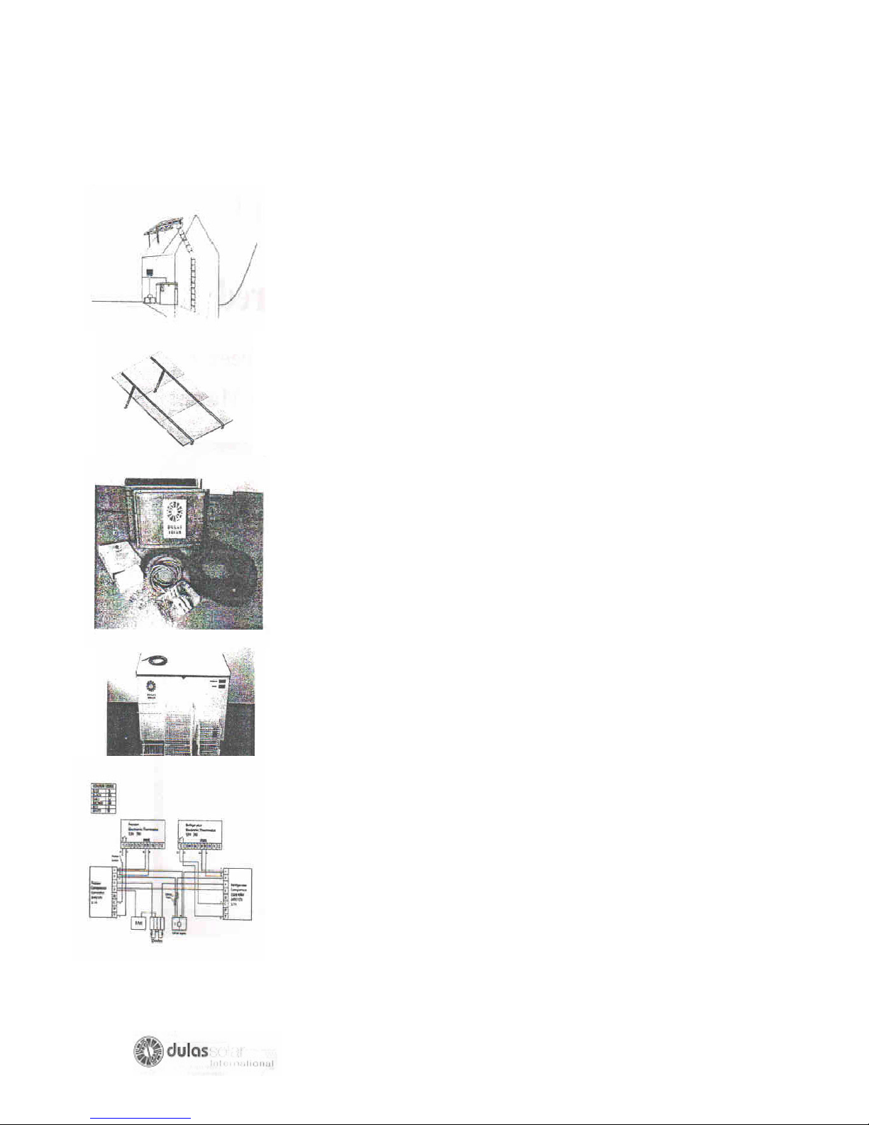
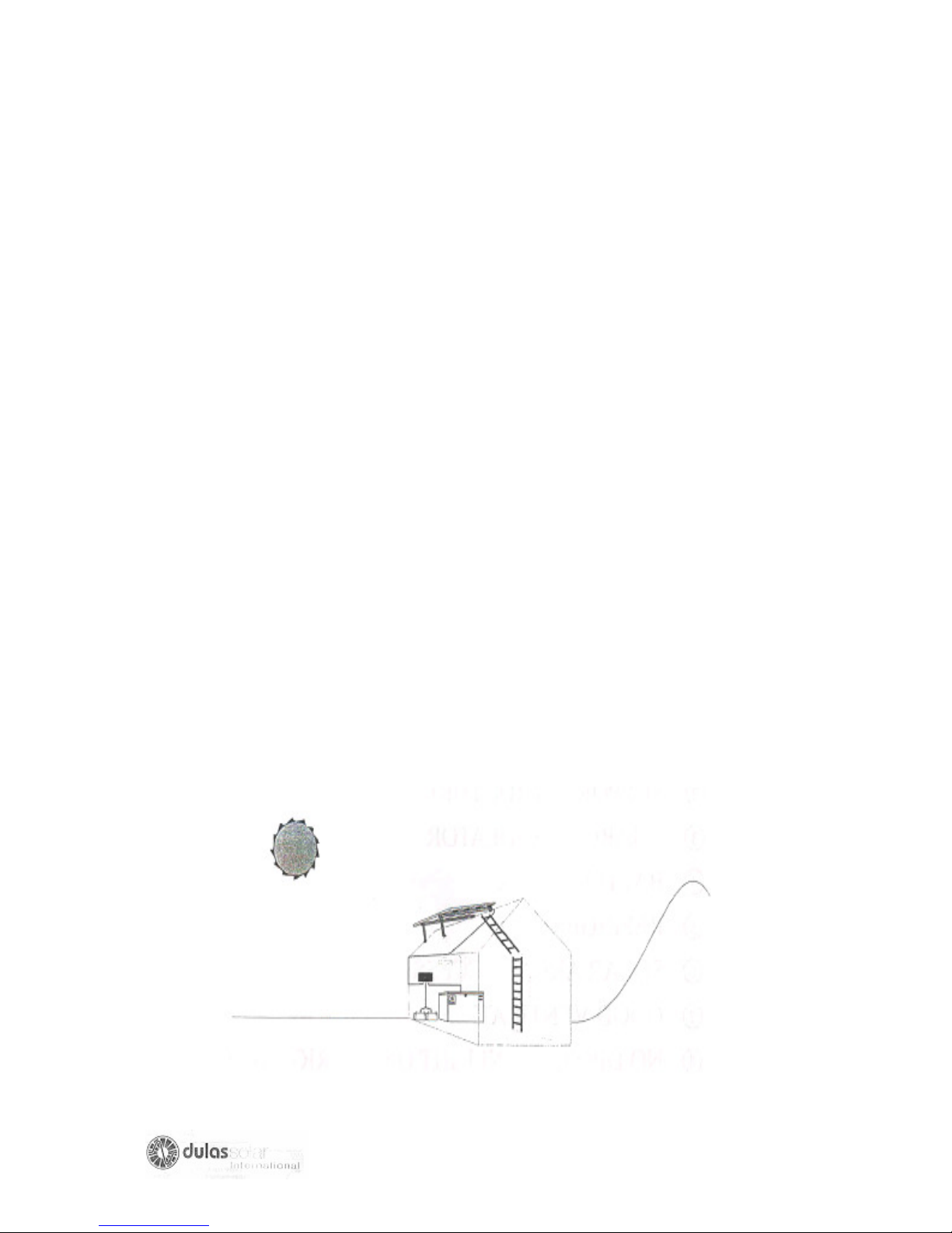
The system when completely installed should look similar to the drawing below.
Each component should have a sensible, well thought out, safe location, allowing
access for routine maintenance.
KNOW YOUR SYSTEM
KNOW YOUR SYSTEM
COMPLETED
8
Page 9
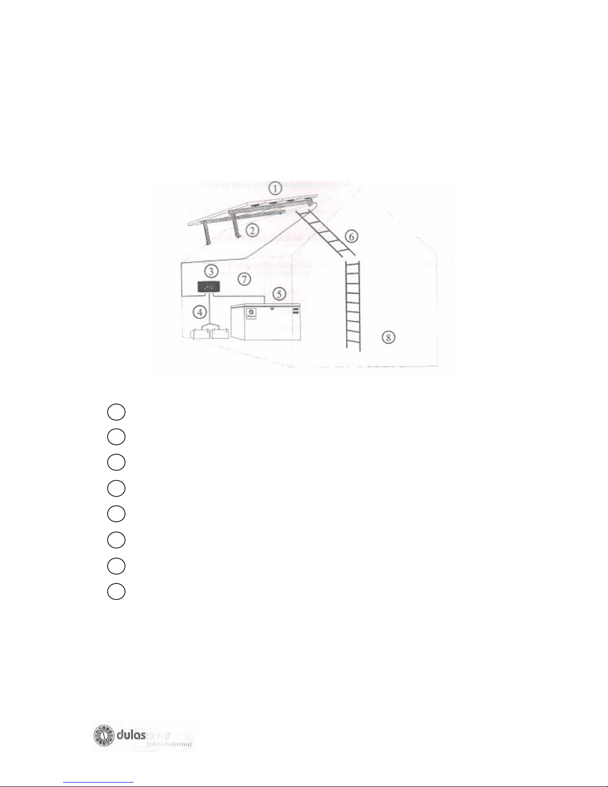
KNOW YOUR SYSTEM
COMPLETED
SOLAR MODULE ARRAY
SUPPORT STRUCTURE
CHARGE REGULATOR
BATTERY PACK
REFRIGERATOR
SOLAR ARRAY ACCESS
GOOD VENTILATION
NO DIRECT SUNLIGHT ON REFRIGERATOR
9
Page 10
SOLAR ARRAY
KYOCERA MODULE ASSEMBLY
PLEASE READ ALL INSTRUCTIONS THOROUGHLY BEFORE COMMENCING
(FOR 12V WIRING LAYOUTS SEE ‘JUNCTION BOX WIRING DIAGRAMS’)
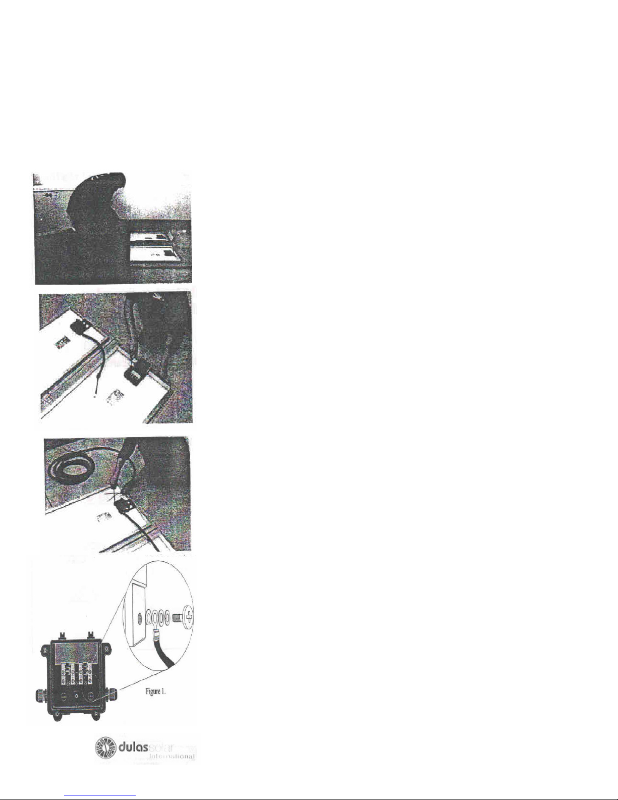
After insuring that all the components are present, remove the
solar (module a.1) from their cardboard boxes and lay them next
to each other on top of the cardboard, with glass facing down.
Do not step on the glass module. BROKEN MODULE CANNOT
BE USED. Arrange the solar modules so that the junction boxes
are all on the same side.
Interconnected the modules with the cables provided (a.3). The
interconnected cable has a crimped ring terminal at each end
which are easily connected to the Kyocera junction boxes as
illustrated below in figure1, (remove plastic unit, screw gland in
place, replace plastic nut and connect cable.)
The array output cable (a.2) must then be connected to the
nearest module (see system wiring diagram), brown or red wire
to +, blue or black wire to -. Ensure that there is sufficient cable
to meet the necessary distance then insert into the junction
boxes as performed previously.
Note: Due to New cable color regulations brown or red can be
used for + ve and blue or black for – ve until 1/4/06 after which
time only brown and blue will be permissible.
Lift the cover of the junction box by removing the four screws.
Place the ring terminal into position and tighten up the terminal
screw until it is gripped securely. Replace the cover of the
junction box with the screw provided ensuring a moisture proof
seal.
10
Page 11
SUPPORT STRUCTURE
ORIENTATION
The solar array must be permanently positioned where the module will receive the
maximum amount of sunshine, however they are very fragile and should not be
located where they may be damaged. A suitable position must be found away from
trees and tall objects, to avoid shading the array, as this will impair the performance
of the module.
Please ensure that the support structure is:
SECURE AND NOT TWISTED
ACCESSIBLE FOR CLEANING
WELL VENTILATED
SAFE FROM SEVERE WEATHER CONDITIONS
NOT SHADED (BETWEEN 7am & 5 pm)
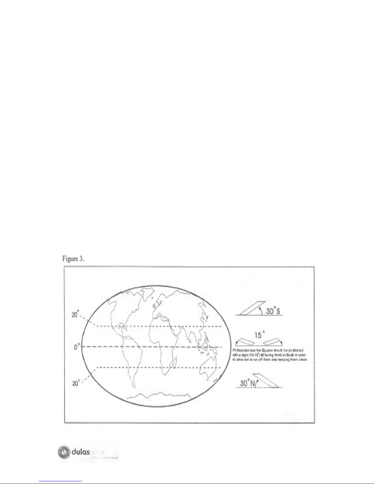
The solar array should face towards the equator- i.e.
South in the Northern Hemisphere,
North in the southern Hemisphere.
The tilt angle of a solar array is dependent on the country in which it is located.
Figure 3 demonstrates common tilt angles. The front of the solar modules must be
cleaned every week or when necessary in dusty Ares.
SUPPORT STRUCTURE
ORIENTATION CONTINUED
11
Page 12
SUPPORT STRUCTURE
ORIENTATION CONTINUED
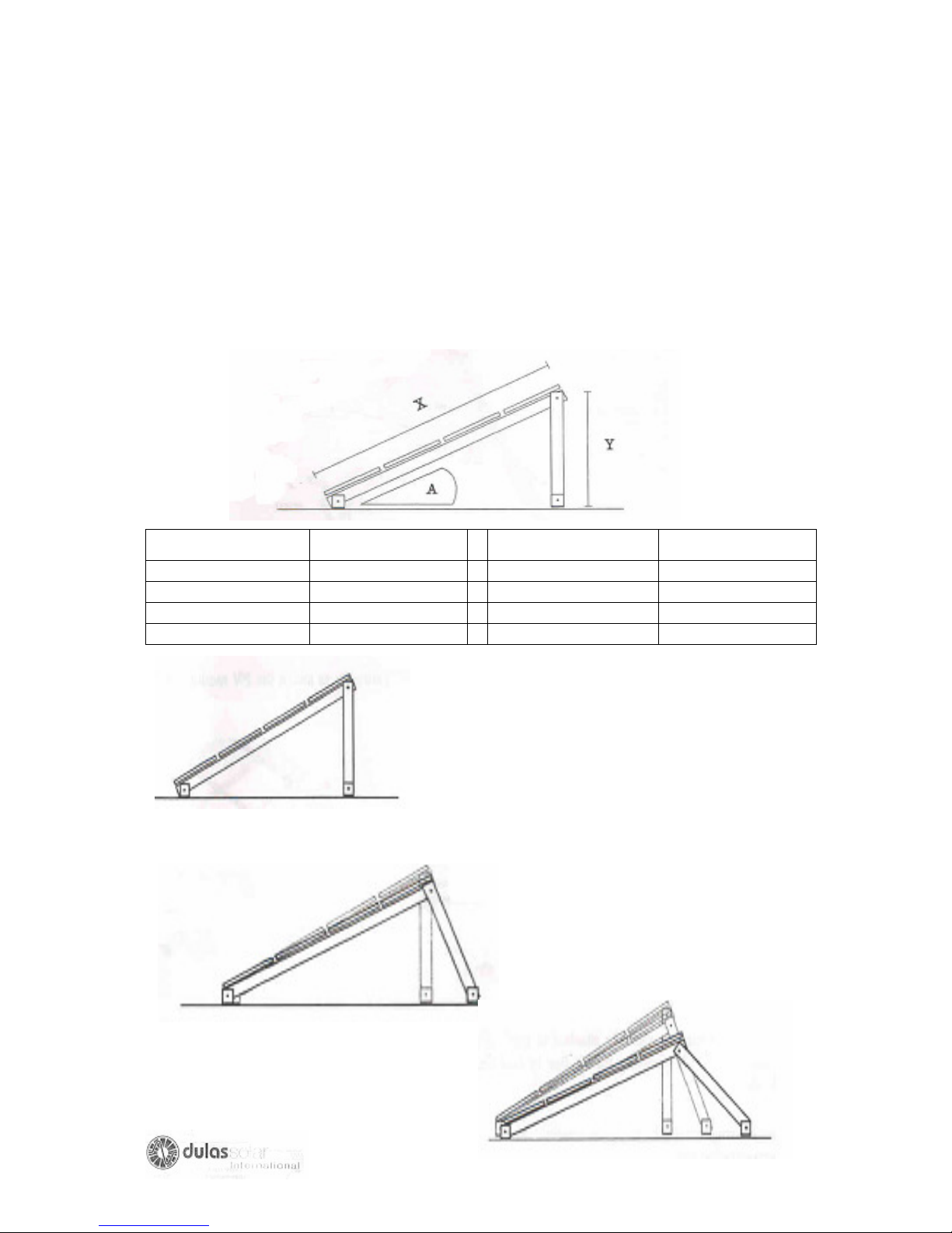
The support structure is made from pre-drilled galvanized steel angle. If you
mounting area cannot be level e.g. you have a sloping roof, then adjusting the foot
mounting holes must make the correct angle.
Use the ratios below to calculate your appropriate angle and follow the diagram to
position the structure accurately.
Required angle (A) Approx. ratio (x:y) Required Angle (A) Approx. ratio(x: y)
100 6:1
150 4:1
200 3:1
250 2.4:1
Changing the position or length of the Tilt legs
can alter module angles.
A protractor can be used to determine
if the correct angle has been acquired.
300 2:1
350 1.75:1
400 1.5:1
450 1.4:1
Always ensure that all bolts are secured
tightly after alterations have been made.
12
Page 13
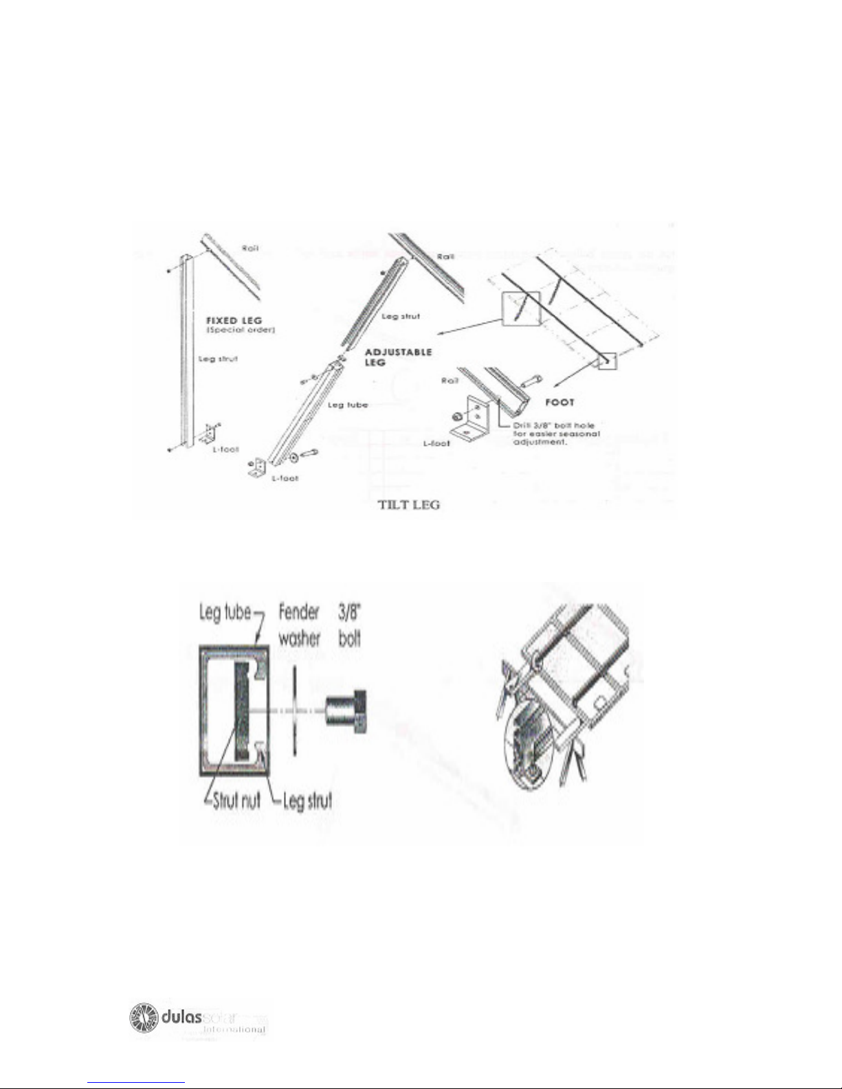
SUPPORT STRUCTURE
ASSEMBLY
1. Assemble the Unirac TLH High Profile tilt Legs as shown in the drawing below.
The UniRac can easily be assembled in any order appropriate to the job site
requirement.
2. Use 3/8” hardware to assemble the UniRac and ¼” hardware to attach the PV
modules to the UniRac
3. UniRac must be securely attached to roof rafter, ground footing or other secure
structural feature. Simply screwing the UniRac to roof decking is not adequate to
withstand high wind loads.
4.leaving as much space as possible at the bottom of the UniRac will minimize
debris accumulation and snow load.
13
Page 14
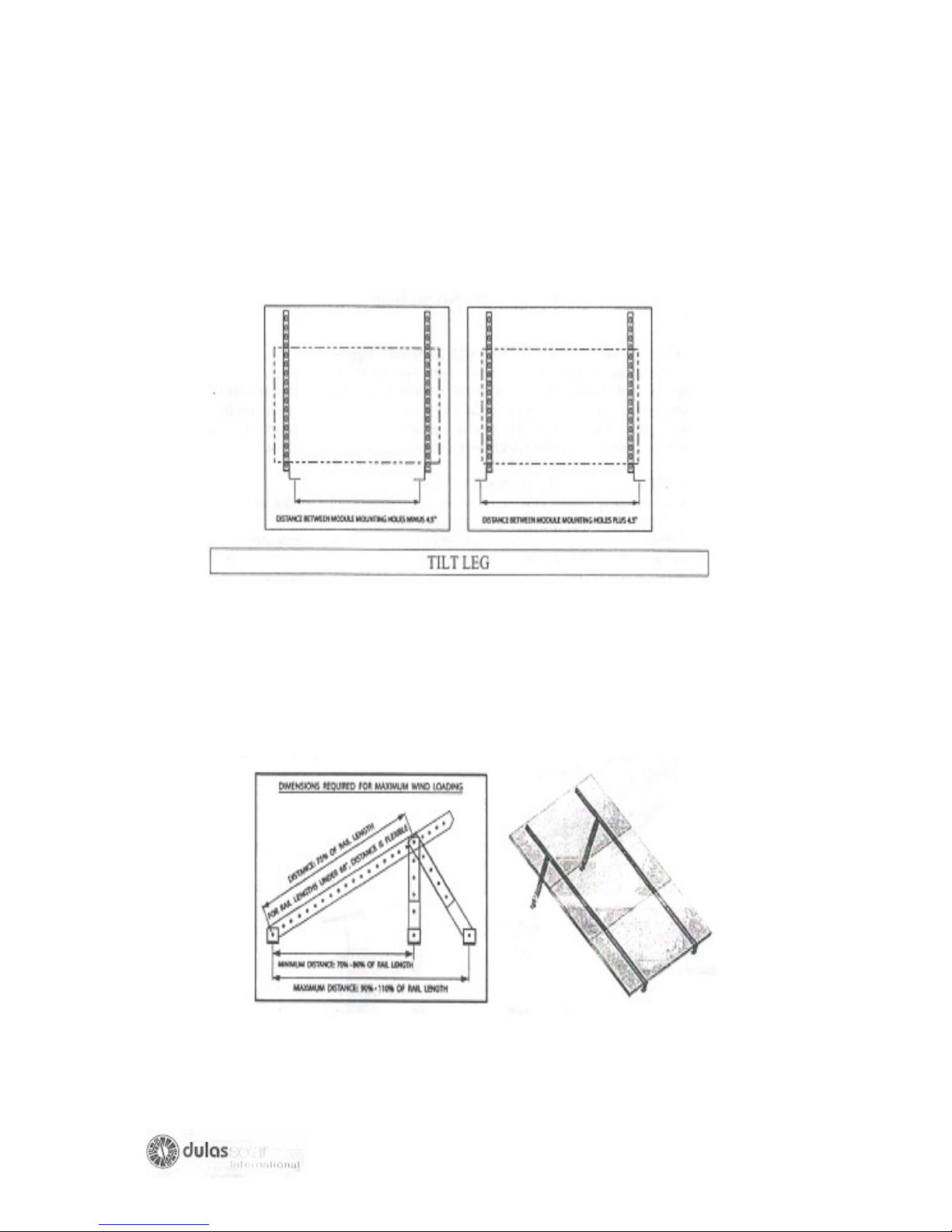
SUPPORT STRUCTURE
LOCATING MOUNTING FEET
5. The drawing below shows two options for setting the width of the Mounting feet. If
possible, mount a PV module to the UniRails to determine the best attachment
method for ontaining the proper distance between the mounting feet.
TILT LEG
6. On UniRacs Tilt Leg Kits, rack tilt can be determined by
A- raising or lowering the Tilt Leg
B- Moving the Tilt leg up or down alog the UniRails,
C-Adjusting the distance between the lower and upper Mounting feet before
final installation.
COMPLETED UNIRAC TLH HIGH-
PROFILE TILT LEGS INSTALLATION
(ADJUSTABLE LEG
)
14
Page 15
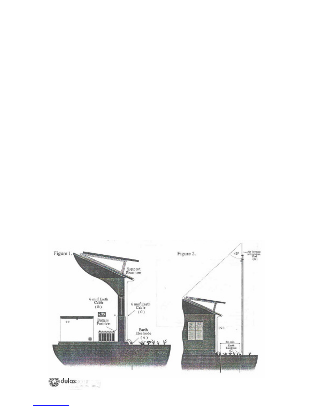
LIGHTNING PROTECTION
MEASURES
LEVEL 1-NO PROTECTIVE MEASURES-NOT RECOMMENDED BY DULAS LTD
Failure to provide protection measures against lightning strike risks damage to the
equipment. In the event of lightning strike the roof mounted solar array, high voltage
may be conducted towards the refrigerator system. This high voltage may damage
the electronic components of the system.
LEVEL 2-LIMITED PROTECTIVE MEASURES (Normally Supplied)
We strongly recommend that at least this level of protection be installed-see figure 1.
Install an earth electrode (earth rod)(A) outside the building-the earth rod should be
at least 2m long. Connect the earth rod with good quality wire (at least 6mm2) to
battery positive (wire B) and with separate similar wire to the Solar array and support
structure (wire C). The earth wire should follow the shortest and straightest path
between the support structure and the earth rod.
LEVEL 3- FULL LIGHTNING CONDUCTOR SYSTEM (Not Supplied)
Assess the risk of lightening strike. Look at other local building- are they fitted with
lightening conductors? Ask local people if TV aerials etc often get struck?
If the installation is at high risk of lightening strike then an additional lightening
conductor and separate earth rod should be installed-see figure 2.
In addition to level 2 protections, install a second earth electrode (D). The distance
between the two earth electrodes must be more than their length. Erect an Air
terminal of Lightning Conductor (E) next to the second earth electrode. The Air
terminal must exceed the height of the Solar Array such that the Solar Array falls
within 450 cone centered on the Air terminal-this is the area that is protected by the
Air Terminal.
15
Page 16

PHOTOVOLTAIC CONTROLLER
INFORMATION
When using Lead-Acid batteries in photovoltaic systems it is important to protect
them against overcharging which would otherwise cause excessive gassing and
overheating, resulting in permanent plate damage and loss of electrolyte. The
Photovoltaic Controller is installed into the system to perform this task. Over –charge
prevention is achieved by limiting the battery voltage to a maximum of around 2.3
Volts per cel at 250c.This cause the charging current to fall naturally before gassing
becomes a problem. The battery can be left charging at this ‘float’ voltage for long
periods with minimal electrolyte loss. A periodic equalization charge is given to avoid
plate sulphation and electrolyte stratification. The battery float voltage is temperature
compensated. In order to measure temperature, a temperature sensor is built in to
the controller. The controller should therefore be mounted as close as possible to the
batteries.
The controller also has an automatic low voltage disconnect facility. In the event of
the batteries not receiving charge, the refrigerator will be disconnected before
permanent battery damage occurs, thus protecting system. Re-connection is
automatic. A Liquid Crystal Display (LCD) indicates the state of charge of the
batteries, and terminals are provided for the connection of batteries, photovoltaic
panels and the refrigerator.
OPERATION
The Photovoltaic Controller is fully automatic in operation. See Steca manual for
installation.
REGULAR FUNCTIONS
The display widow on front panel shows system and error message, the left button
on front panel can be used to switch display windows or calling up settings and the
right button is used as a manual load switch, or confirmation button in the
programme mode. The three displays, which are the most relevant to the operation
of the refrigerator, are as follows:
1. CORRECT OPERATION: Indicated by a smiling face in the display window. A sad
face indicates a fault. The reference number in the display can then be looked up in
the manual to give the meaning of the error and the cause/remedy.
2. STATE OF CHARGE: Indicated by the bar graph (SOC) and a percentage on the
display. When the state of charge is 50% or less, icepacks should not be frozen.
3. LOAD DISCONNECTION: The refrigerator is disconnected when the state of
charge drop to 30%. The SOC bar value, or the voltage value, flashes. The face
looks sad until the reconnection set point is reached.
THE LCD ALSO PERFORMS VARIOUS OTHER FUNCTIONS. CONSULT THE
MANUFACTURER’S HANDBOOK FOR FURTHER INFORMATION.
16
Page 17
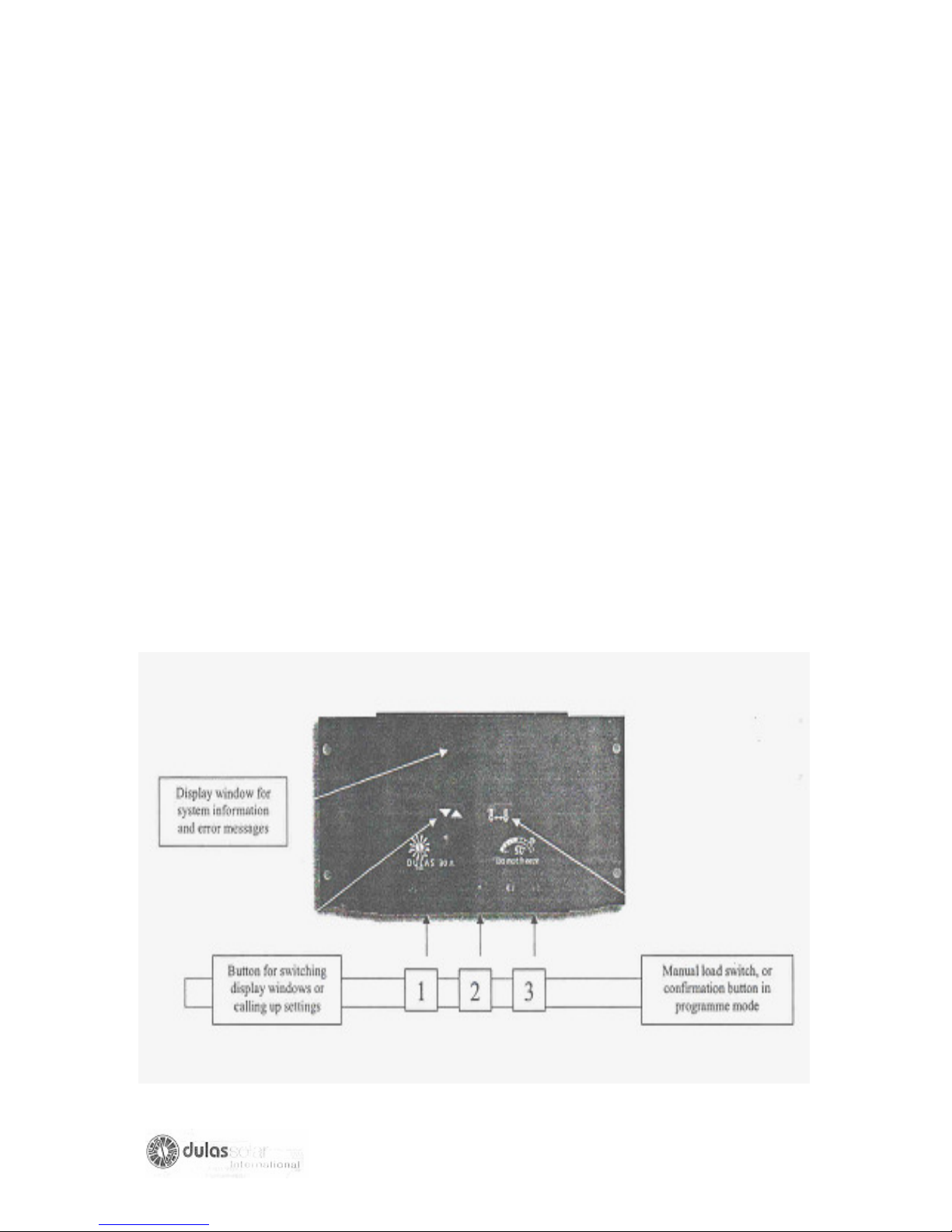
PHOTOVOLTAIC CONTROLLER
INSTALLATION
The unit should be installed in a dry location with clear space around it, to allow heat
generated at the rear of the unit to be dissipated. The unit is fixed to the wall so that
the terminals are at the bottom and the fins running vertically.
Installation instructions
1. Fix the Photovoltaic Controller to the wall with plugs and screws.
2. Connect the battery cable to the central pair of terminal on the unit (2). Taking
care to ensure correct polarity (brown or red to +, blue or black to -).
3. The array output cable (a.2) must be connected AFTER the batteries, to the left
hand pair of terminal on the unit (1) (brown or red to +, blue or black to -). BE
AWARE OF LARGE VOLTAGES. Cover the array or connect at night.
4. The refrigerator is connected to the right hand pair of terminal (3) on the regulator,
taking care to ensure correct polarity (brown or red to +, blue or black to -).
5. Support the cables using the clips provided.
17
Page 18
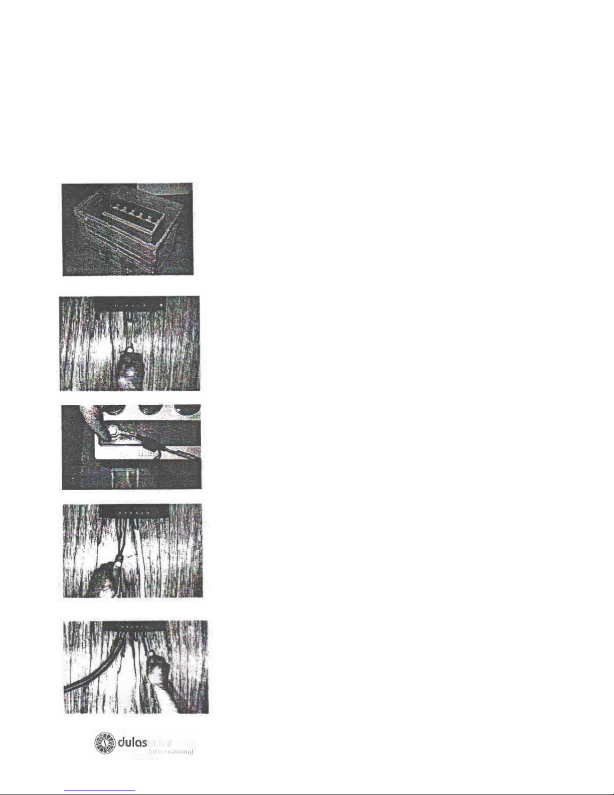
COMMISSION THE BATTERIES
CONNECT THE BATTERIES
THE BATTERY BOX MUST ALWAYS BE LOCATED IN A VERY WELL
VENTILATED AREA AS THE BATTERIES GENERATE HYDROGEN, WHICH IS
AN EXPLOSIVE GAS.
batteries into the empty box, ensuring not to
lift by the terminal points. THE BATTERIES
ARE NOW EXTREMELY HEAVY.
1. After choosing a final location, carefully place
2. Connect the battery –to-regulator cable to the regulator
FIRST, brown or red to + and blue to – THEN to the
battery. Secure in place using the nuts, bolts and
washers provided. Insert a spare fuse (d.7) into the
fuse holder on the battery-to-regulator cable. Any
problem refers to the manufacturers handbook
provided.
3. Apply petroleum jelly or similar to each battery
terminal-this help avoid corrosion.
4. Commence charging of the batteries immediately by
connecting the solar array cable to the PV controller.
DO NOT CONNECT THE REFRIGERATOR, as the
batteries need an initial charging of two sunny days for
optimum performance.
5. Once the batteries are ready for operation (after two
good sunny days of charging), the refrigerator can be
connected.
18
Page 19
.
THE REFRIGERATOR /FREEZER
POSITIONING
DO NOT POSITION THE VC150 REFRIGERATOR/FREEZER IN DIRECT
SUNLIGHT.
ENSURE THAT THE REFRIGERATOR IS WELL VENTILATED, ESPECIALLY
THE VENTILATION GRILLS AND CONDENSER.
WE RECOMMEND LEAVING a 500mm GAP AT EACH END OF THE
REFRIGERATOR
NEVER OBSTRUCT THE TEMPERATURE OR REGULATOR DISPLAYS
ENSURE THAT THE BATTERY BOX AND BATTERIES CAN BE INSPECTED
WHEN NECESSARY
NEVER BLOCK THE CIRCULAR COMPRESSOR VENTILATION FAN AT THE
FRONT
STARTING THE FRIDGE
The VC150 refrigerator is designed for continuous operation, therefore an ON/OFF
switch is not provided, as it is not necessary. The VC150 Freezer however, does not
an ON/OFF switch to allow for defrosting? This is situated at the rear right of the
cabinet, as viewed from the front, above the cable gland (see General Layout
diagram)
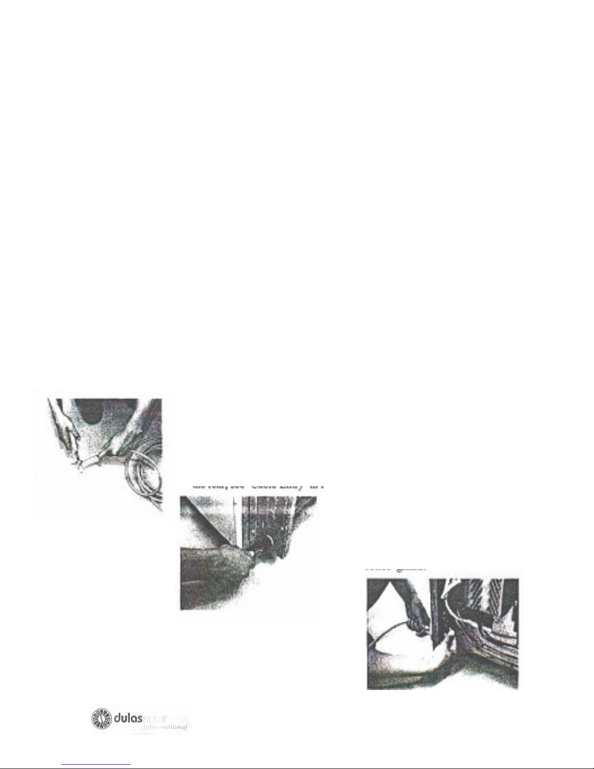
The VC150 refrigerator/freezer is operational when the power cable is connected to
the controller.
a) Strip the power cable to reveal 10 mm of brown or red (+) and blue or black (-)
wire.
b) Insert the cable into the black strain relief gland, located at
the rear, see ‘Cable Entry’ in the General Layout Diagram.
.
c) Connect to + & - terminals
on opposite side of the
strain relief gland
.
d) TIGHTEN THE TERMINALS SECURELY, TIGHTEN
THE STRAIN RELIEF GLAND SECURELY.
19
Page 20
THE REFRIGERATOR/FREEZER
LOADING
IN ORDER TO KEEP INTERNAL TEMPERATURE OPTIMUM AND MINIMISE
ENERGY CONSUMPTION ONLY OPEN THE LID WHEN STRICTLY NECESSARY
AND ALWAYS REPLACE INNER FOAM LIDS
The VC150 refrigerator /freezer has two components, see General layout Diagram:
1) The smaller freezer (ice pack) compartment to left.
2) The larger refrigerator (vaccine) compartment to the right.
ICE PACKS: When frozen ice packs are needed; switch the freezer ON, insert ice
packs with basket into the LEFT compartment. Ice packs must be in contact with the
freezer compartment walls for effective freezing. A wire basket is provided to hold
the ice packs against the walls of the compartment. Only three sided of the
compartment can be used for freezing ice packs as the fourth has the thermostat
sensor mounted on it. A small wire cage protects the sensor. Simply simply reaching
inside the basket, and sliding the ice packs up and out of the ice freezing area
remove ice packs. Frozen ice packs can be stored in the space inside the wire
basket. The freezer can freeze nine ice packs simultaneously. Remember to switch
freezer OFF when not in use – to save energy.
WARNING: STANDARD SYSTEMS ARE DESIGNED TO ONLY FREEZE 2.4 KG’S
OF ICE PER 24 HOURS, FREEZING MORE WILL FLATTEN THE BATTERIES.
VACCINES: The refrigerator compartment situated to the RIGHT is in constant
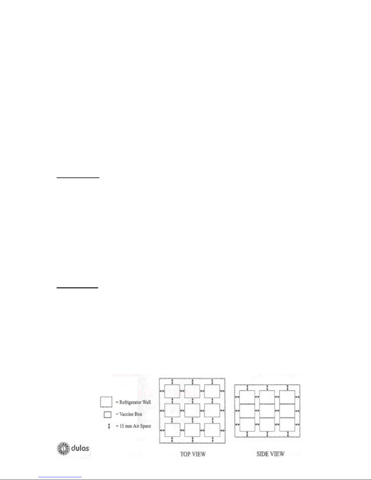
operation. The wire baskets in the refrigerator compartment are designed to prevent
the contents of the compartment from touching the cold sides, and to encourage the
circulation of air. Good air circulation will help the refrigerator to maintain an even
temperature throughout the compartment. The contents of the compartment should
be arranged to allow good air circulation. In order to save energy, try to keep the lid
open for as short a time as possible. Try to allocate a certain space for each different
type of vaccine, so that they may be located rapidly. Check the vaccine labels and
adhere to any special requirements, always use before expiry date (store older
vaccines on top).
WARNING: ALWAYS FOLLOW THESE VACCINE STORAGE GUIDELINES
20
Page 21
SINGLE FRIDGE CONTROLLER
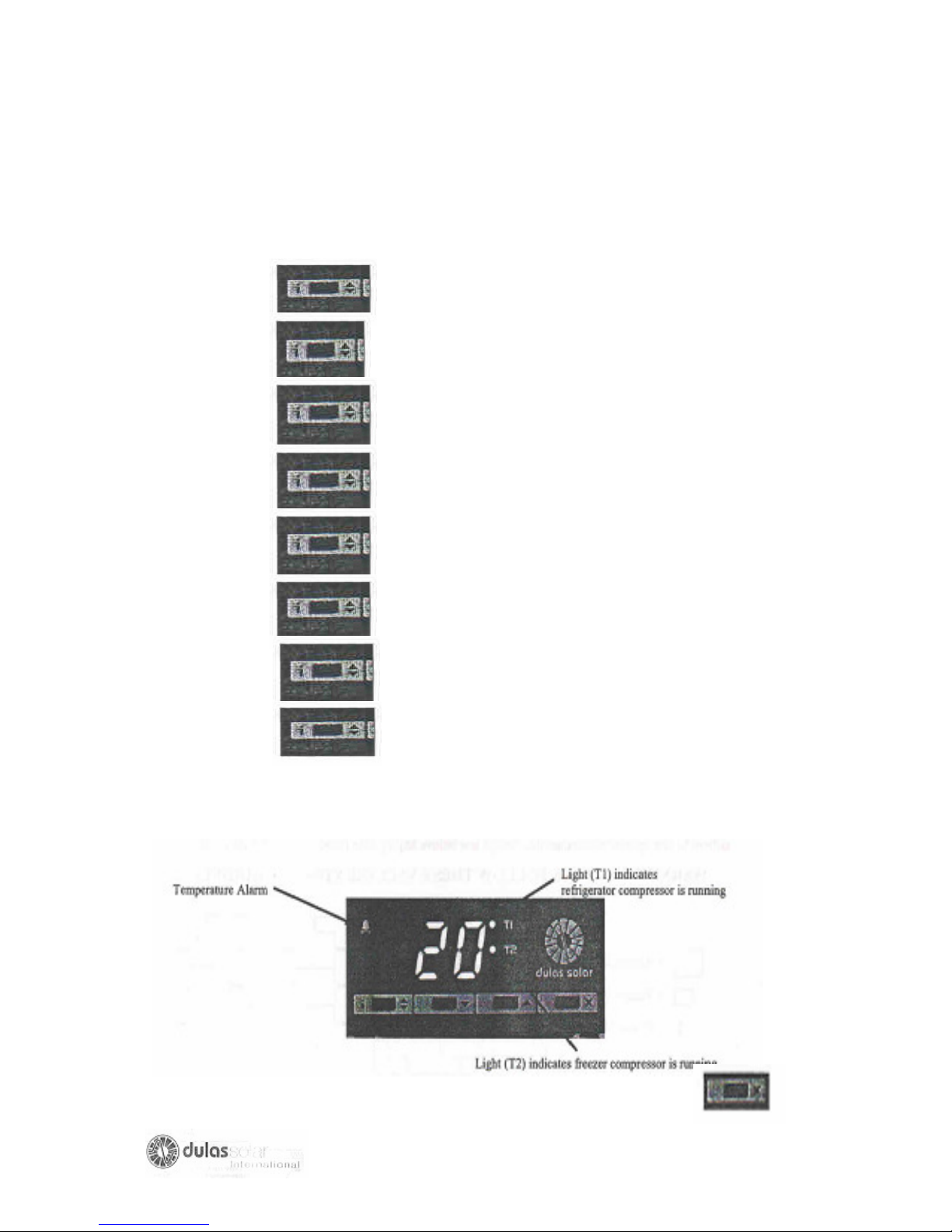
The controller normally displays vaccine temperature. To see freezer temperature
follow these steps:
Press -the controller says hi
Hold -the controller gives the high temperature (eg08)
Release -the controller says Lo
Hold -the controller gives the low temperature (eg03)
Release -the controller says t1
Hold -the controller give vaccines temperature (eg06)
Release -the controller says t2
Hold -the controller gives freezer temperature (eg -6)
Do nothing for 10 seconds and the display reverts to vaccine temperature.
The temperature alarm has a sound warming (beep). To cancel press
21
Page 22

ROUTINE MAINTENANCE
CHECK TEMPERATURE
The temperature the refrigerator should be checked each morning and afternoon.
The temperature must be between 20 C and +80C.If the temperature is not within this
range then something is wrong and the vaccines will be unusable. Cnsult the W.H.O.
fault finding and repair of Photovoltaic (provided with each refrigerator).
Check the temperature by placing a thermometer next to the temperature sensor
(situated at the rear of the right hand compartment) and closing the lid. After five
minutes, remove the thermometer, read and record the temperature on a relevant
data sheet.
CHECK LIGHTS
Check that the warning lights on the Photovoltaic charge regulator are not lit, and
that operation is normal. If there is a problem then record this and refer to the
W.H.O. fault finding and repair of the Photovoltaic refrigerators (attached).
DEFROSTING
If there is a build up of ice (5 mm or more) on the walls of the freezer, then it must be
removed by defrosting. The refrigerator can be kept running or cleaned at the same
time.
WARNING: NEVER REMOVE ICE WITH KNIVES OR SHARP OBJECT OR USE
SCOURING POWDER, ABRASIVE CLEANERS OR STEEL WOOL AS THIS WILL
DAMAGE THE METAL PLATING AND CAUSE CORROSION.
1) If the refrigerator is to be cleaned, move the vaccines into another fridge or a
cold box, which can ensure the correct temperature, is sustained throughout the
defrosting process.
2) Switch the freezer OFF (see general Layout diagram)
3) Open the outer Lid, remove the appropriate inner lid, leaving the freezer for at
least 30 minutes to warm up.
4) When possible, remove ice with fingers or wooden /plastic tools.
5) Hand-warm water can be used to assist the defrosting process.
6) Dry the ice compartment after the ice has melted and cleans the vaccine
compartment with soapy water, and then dries it carefully.
7) Clean the outer lid seal (talcum powder can be sprinkled on it prevent it from
sticking).
8) Switch the Freezer backs ON and closes the lid.
9) After 2 hours check the temperature. Wait until the inside temperature has fallen
to between 20C and +80C and the compressor has stopped running continuously.
10) Return the vaccines to the refrigerator and close the lids.
DEFROSTING MUST BE COMPLETED AS QUICKLY AS POSSIBLE TO
PREVENT DAMAGE TO THE VACCINES
22
Page 23
ROUTINE MAINTENANCE
CHECKING THE LID SEAL
The lid seal is the most likely area of heat penetration. If the lid hinges are wrongly
aligned or the lid seal damaged, the system will have to work harder to maintain the
vaccine temperature. When the batteries run out of energy the system will fail,
therefore the lid seal must be checked regularly.
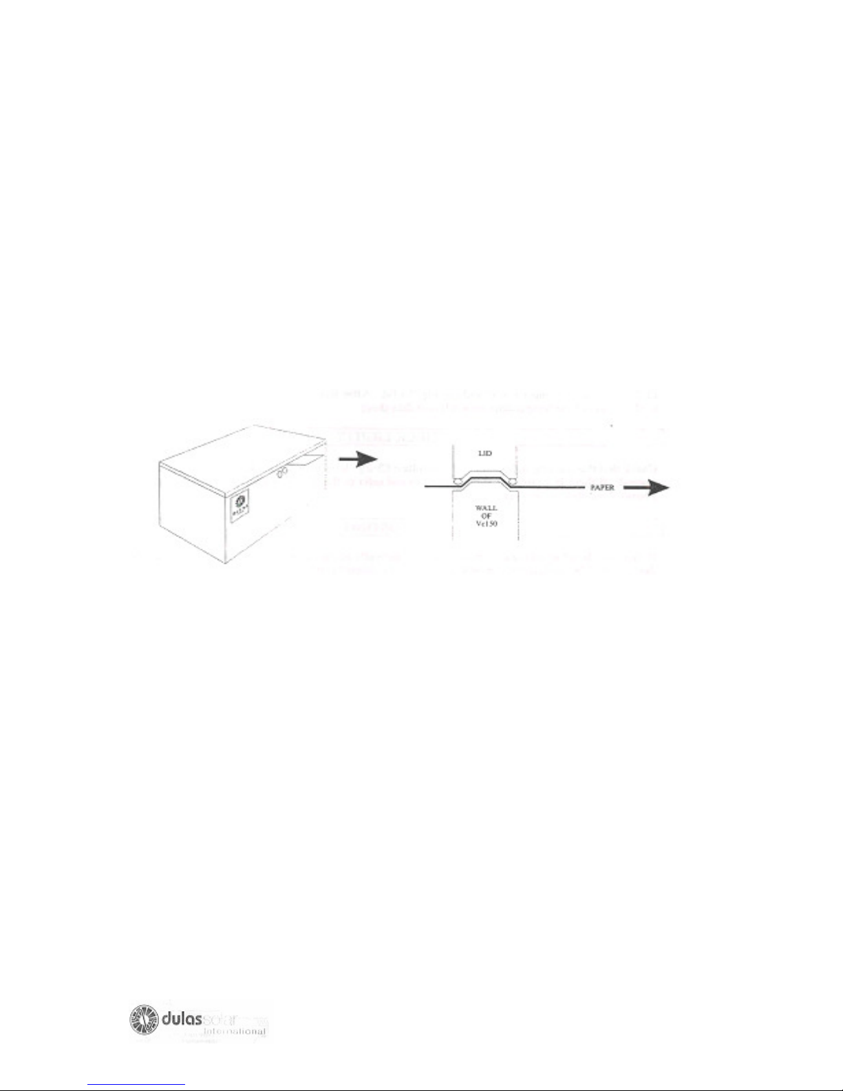
The easiest way to check your seal is to position a piece of paper between the lid
and the wall, then after the lid, try to remove the paper.
Check the seal in this way around the entire lid, especially the corners. If the paper
moves easily, then the lid seal needs attention, it may need to be re-guled or
completely replaced, alternatively the refrigerator hinges may need adjusting so that
the lid is sitting correctly.
CHECK FOR SHADOWS
Any shading of the array (solar panels) will reduce it’s output, therefore the array
must be checked three times in one day, at 7 am, 12 midday and 5 pm, to ensure all
possible shade sources are eliminated.
Cut back any bushes or trees, which cause shading, seeking permission and
explaining why firstly.
Move anything that has been placed in front of the array, and may block the
sunshine falling on it.
If there have been any new buildings or structures erected which cause shadowing,
then the array must be moved to an unshaded area.
CHECK ALL CONNECTIONS
Check each electrical connection thoroughly, make sure every nut and bolt, are
secured tightly.
23
Page 24
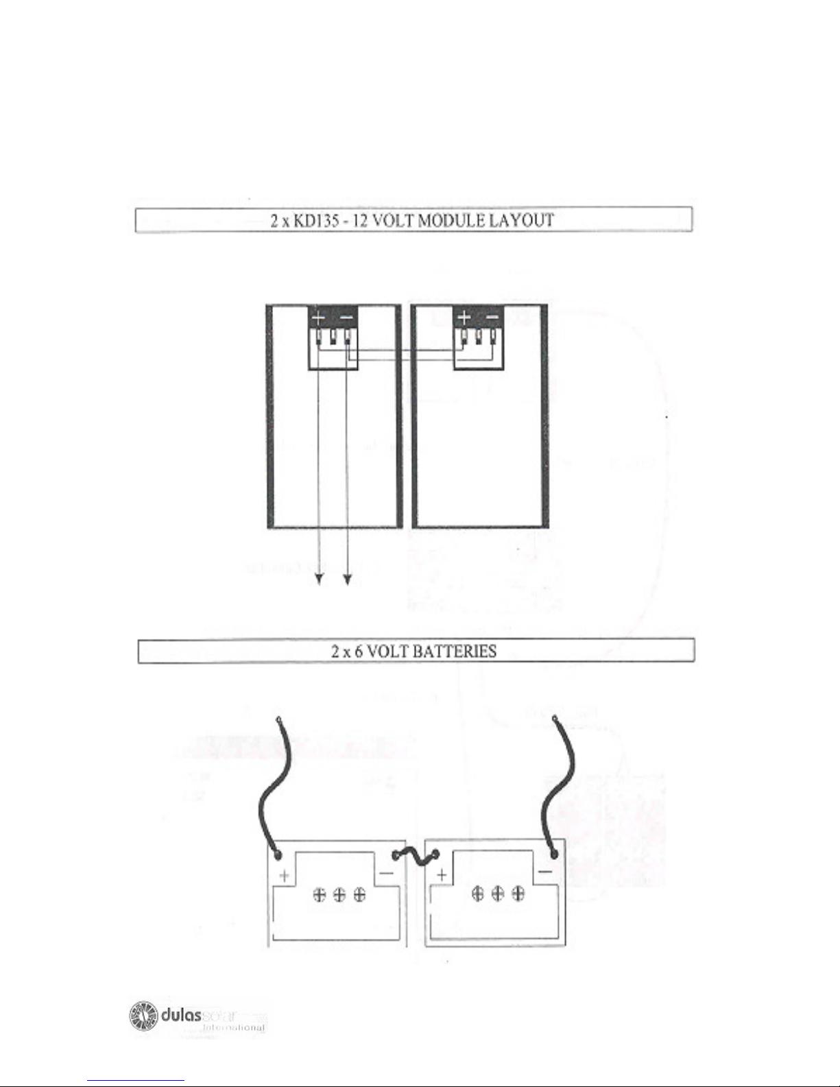
MODULE AND BATTERY WIRING DIAGRAMS
SYSTEM WIRING DIAGRAM
24
Page 25
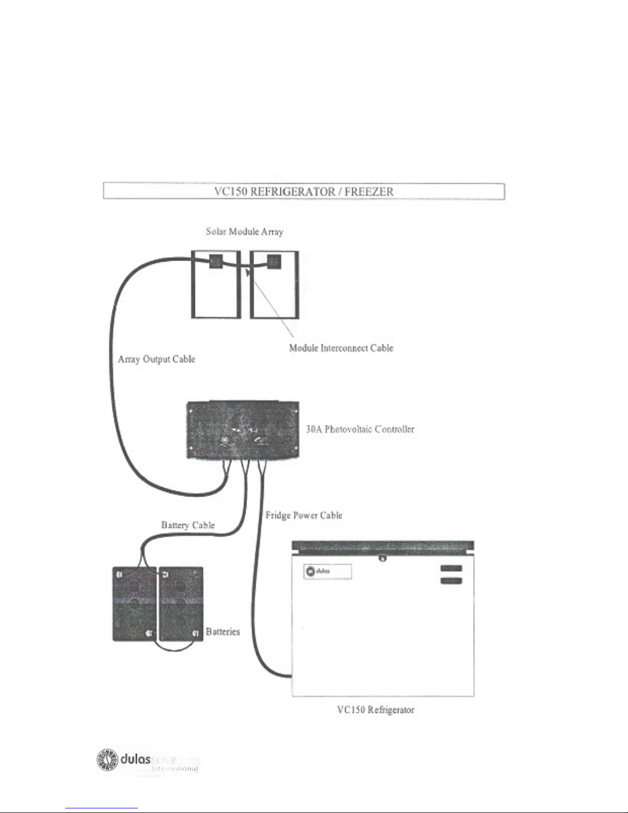
SYSTEM WIRING DIAGRAM
GENERAL LAYOUT DIAGRAM
25
Page 26
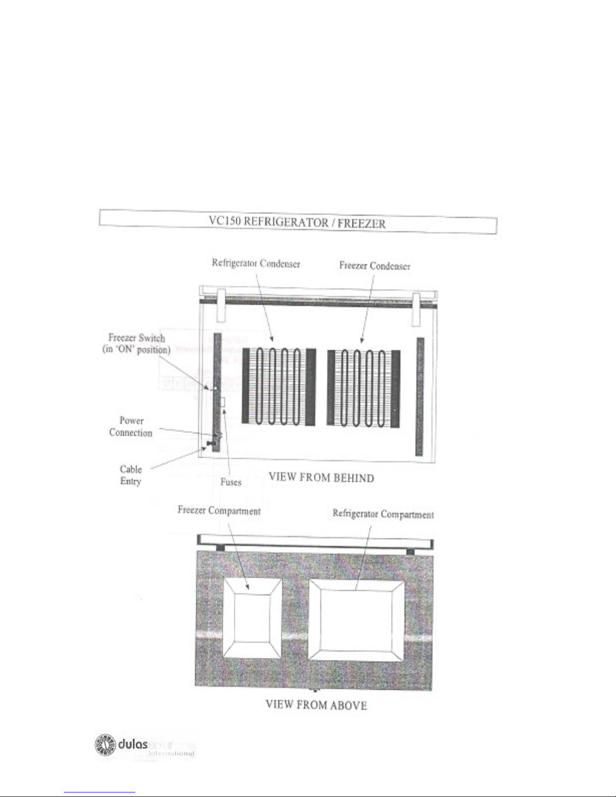
GENERAL LAYOUT DIAGRAM
ELECTRICAL CIRCUIT DIAGRAM
26
Page 27
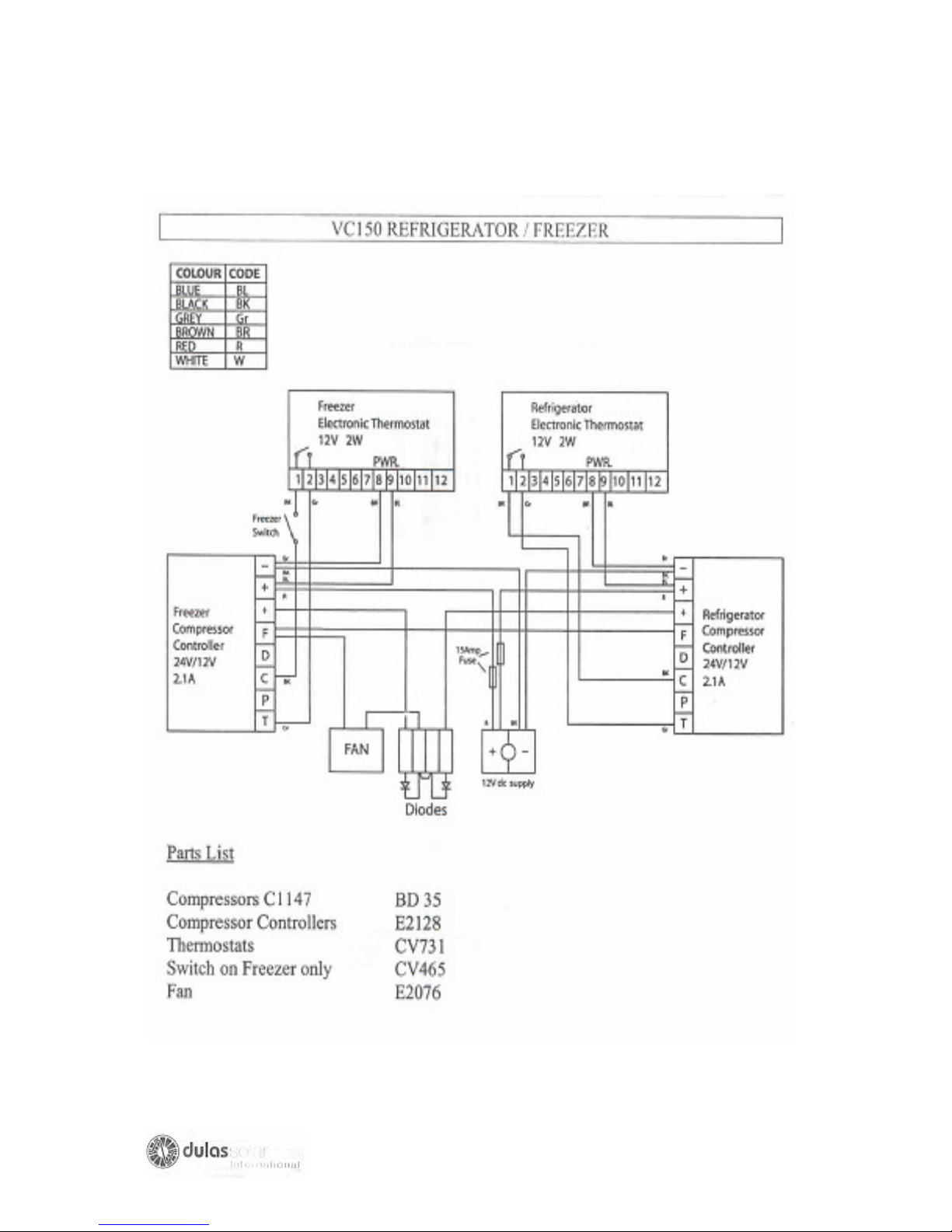
ELECTRICAL CIRCUIT DIAGRAM
REFRIGERATION CIRCUIT DIAGRAM
27
Page 28
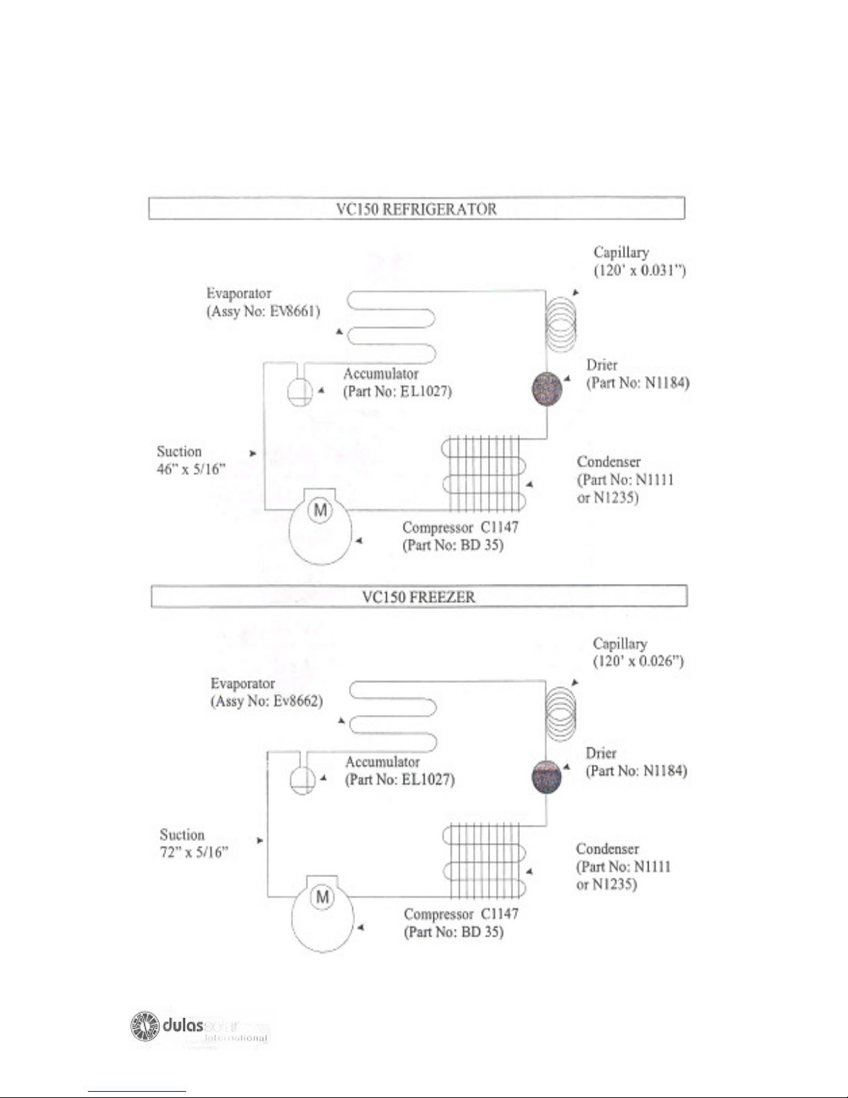
REFRIGERATION CIRCUIT DIAGRAM
28
Page 29
SECTION II
29
Page 30

WORLD HEALTH ORGANISATION EXPANDED
PROGRAMME ON IMMUNIZATION
FAULT FINDING & REPAIR
OF
PHOTOVOLTAIC REFRIGERATOR
A TECHNICIAN’S HANDBOOK
30
Page 31

FAULT FINDING & REPAIR OF
PHOTOVOLTAIC REFRIGERATOR
CONTENTS Page No.
PART 1
:
INTRODUCTION
A: SCOPE
B: HOW A SOLAR PHOTOVOALTAIC REFRIFERATOR WORKS
C:
SAFETY CONSIDERATIONS
PART 2: MAINTENANCE AND SERVICING WORK
A: PREPARATION
B: HOW TO MEASURE
2. Electricity - 2.1 General
- 2.2 Voltage
- 2.3 Current
3. Resistance
4. State of Charge of Batteries
5. Tilt and Direction of Solar Array
6. Open and short circuit measurements
on the Photovoltaic Array
1. Temperature
C: MAINTENANCE AND SERVICING
1. Introduction
2. Cleaning the solar array
3. Preventing solar array shadowing
4. Inspection of electrical cables
5. Checking the performance of the solar array
6. Battery maintenance
7. Defrosting the refrigerator
8. Cleaning
31
Page 32

PART 3: FAULT FINDING AND REPAIR TASKS
A: INTRODUCTION
B: HOW TO FIND A FAULT
1. Determine the symptoms
2. Carry out Preliminary check
C: FAULT FINDING CHART
Chart No. 1
Chart No. 2
Chart No. 3
D: FAULT FINDING AND REPAIR TASK DESCRIPTION
1. User maintenance tasks
2. Thermostat
3. Fuse Blown in compressor controller
4. Fuse Blown in charge regulator
5. Low state of charge of batteries
6. Wiring
7. Solar photovoltaic array
8. Compressor controller
9. Charge regulator
10. Condenser Fans
11. Cooling current
12. Compressor
13. System sizing
E: REPAIR TECHNIQUES
1. Introduction
2. Replacing a module
3. Adjusting a thermostat
4. Replacing a power cable
5. Replacing the charge regulator
6. Replacing the compressor controller
7. Replacing a condenser Fan
8. Replacing a battery
PART 4: RECORD-KEEPING
PART 5: USER TRAINING
GLOSSARY OF TERMS
ANNEX 1. Component layouts of commonly used photovoltaic refrigerator
32
Page 33

ANNEX 2. Tools and measuring Instruments
PART 1: INTRODUCTION
A: Scope
This handbook is published by the World Health Organization Expanded programme
on Immunization.
It is general handbook for use by service and repair technicians responsible for the
maintenance and repair of solar photovoltaic powered refrigerator.These
refrigerators are used for storing vaccines and freezing ice packs in health clinics.
This handbook applies specifically to 12 to 14 volt stand-alone photovoltaic powered
refrigerators and should not be used for any other type of refrigerator. Stand-alone
means here that the solar array does not power any other device (e.g. lights) and
refrigerator it powered only from the solar array.
The handbook should be considered a supplement to maintenance and repair
manual supplied by the solar refrigerator manufacturer, which define maintenance
and repair activities specific to their model of refrigerator.
Each technician should have his or her own copy of this handbook. This handbook is
one in a series of technician’s handbooks for medical refrigerators and makes
reference to other WHO handbooks on compression refrigerators. A complete list is
shown on the inside front cover of this document. You should ensure you have
copies of this also.
In addition to this handbook two others are available for solar Photovoltaic
refrigerators:
• A USERS HANDBOOK for photovoltaic refrigerators.
• AN INSTALLATION HANDBOOK for photovoltaic refrigerators
You should ensure you have copies of the USERS HANDBOOK in case a user
responsible for a solar refrigerator you visit does not have one.
It is not necessary for you to have a copy of the INSTALLATION HANDBOOK unless
you are responsible for installing and repairing them.
33
Page 34

B: HOW A SOLAR PHOTOVOLTAIC REFRIGERATOR WORKS
- A photovoltaic refrigerator is similar to an ordinary compressor refrigerator
except that the compressor is powered from direct current (d.c) electricity
supplied from a solar array. A photovoltaic refrigerator system compries the
following principal parts:
- The solar photovoltaic array containing solar cells, which convert sunlight into
direct current (DC) electricity. It has no moving parts and is a highly reliable
component.
- Batteries, which are used to store electricity for periods when there is no
sunlight.
- A charge regulator (an electronic unit), which is used to prevent the batteries
from being damaged by too much electricity from the array or from too much
electricity being drawn by refrigerator.
- A compressor, which sealed unit.
- A compressor controller which:
• converts D.C. current electricity provided from the array and/or
batteries into a form which will drive compressor.
• prevents damage to the compressor if overloaded, and also protects
the batteries against deep discharge.
These parts are connected together to make:
- A Solar Powered Battery Charger, and
- A battery powered refrigerator,
which when combined, becomes a refrigerator powered by sunlight, which we call a
solar photovoltaic refrigerator (and can be a Solar Refrigerator, Photovoltaic
Refrigerator or PV Refrigerator).
34
Page 35
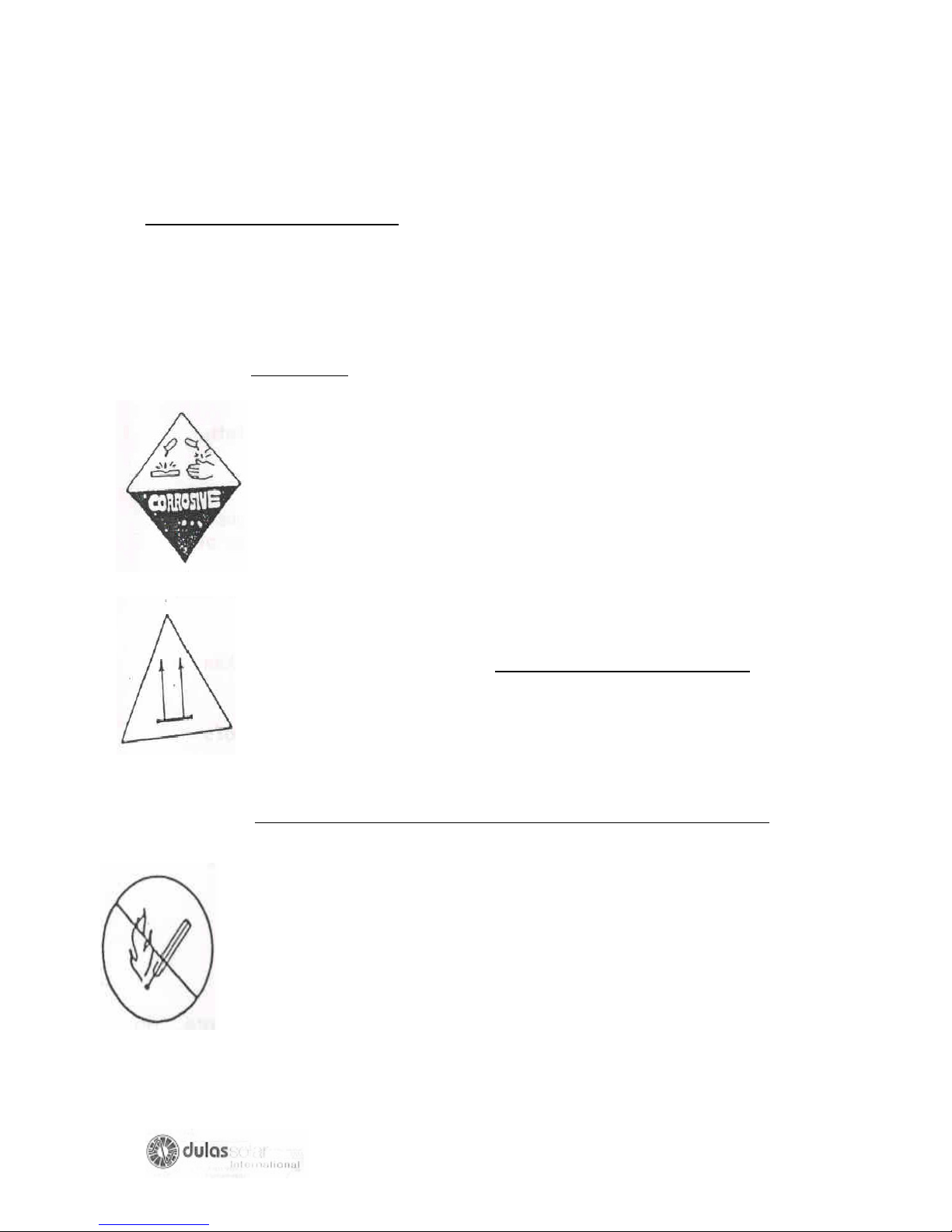
C: SAFETY CONSIDERATIONS
TECHNICIANS and USERS MUST ALWAYS take following precautions when
transporting, handling, installing, maintaining and using photovoltaic refrigerator
systems:
BATTERIES
BATTERIES CONTAIN ACID WHICH CAN CAUSE ACID
BURNS ON SKIN OR BLINDNESS IF IN CONTACT WITH
THE EYE. The acid will also damage clothes.
- avoid spilling or splashing battery acid especially in transport
- always keep the batteries upright
- carry batteries carefully (do not carry them on your head).
- attach batteries when transporting them.
- always use a funnel or plastic bottle with a spout to add distilled
water.
BATTERIES ALSO GIVE OFF GASES WHICH ARE EXPLOSIVE:
- make sure that containers provided are well ventilated and that
they are placed in a well ventilated room.
- keep naked flames and lighted cigarettes well away from
batteries.
- always switch off power from the array and to the refrigerator
before disconnecting the batteries (to prevent sparks). Provide
well ventilated containers were not provided when installed.
- Keep un-insulated tools and metal jewellery away from batteries
they may cause a spark if they come into contact with the
terminals.
35
Page 36
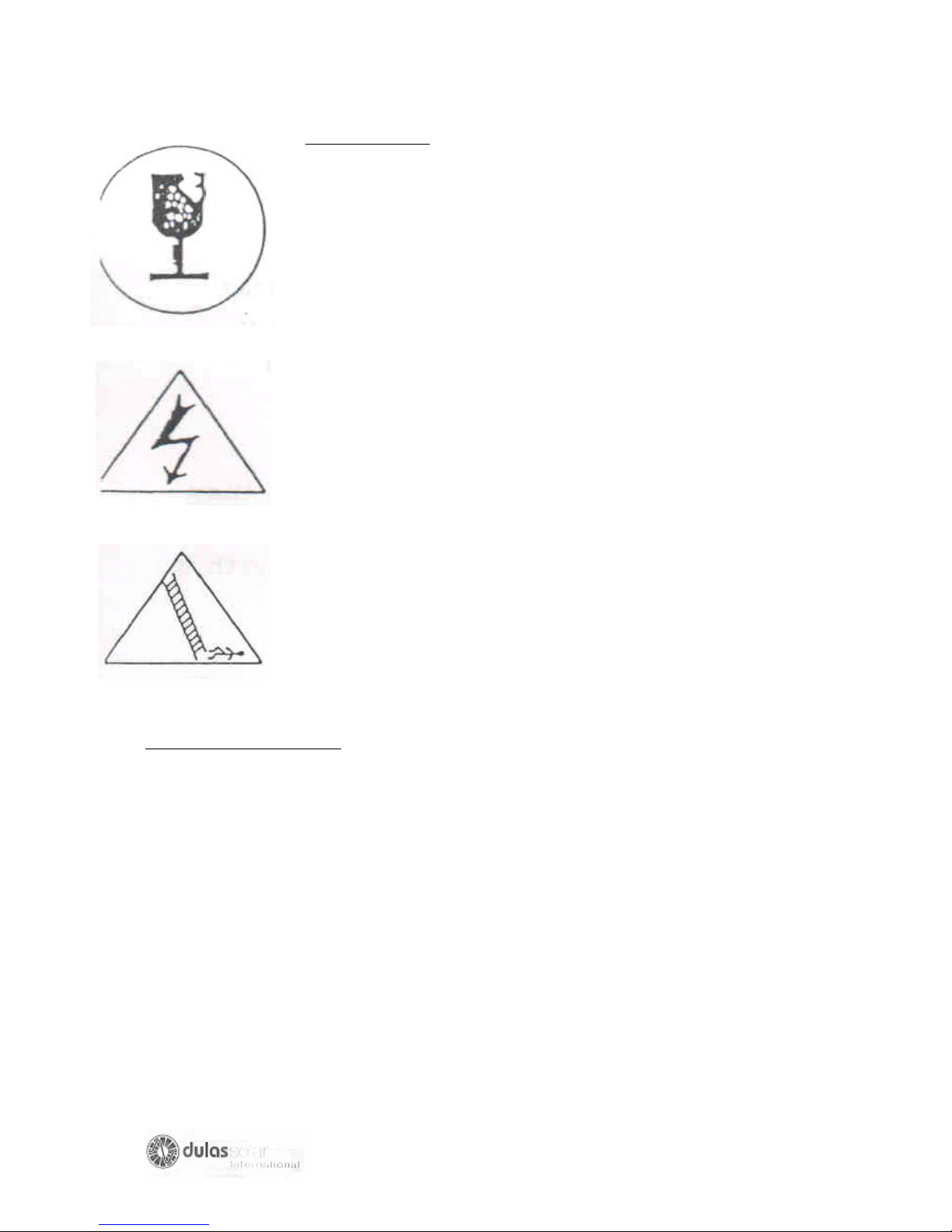
SOLAR ARRAY
Photovoltaic modules have a glass cover; always carry and
Transport them carefully.
There is a risk of receiving an electric shock from a solar array.
Always take the following precautions when undertaking
servicing or repair work:
- cover the solar array with a sheet or cloth.
- use insulated tools.
Solar array are often mounted on a roof but must, however be
cleaned regularly. There is risk of falling from a roof.
-make sure that the user has an easy and safe way of access to
clean the array
-always use good ladders and position them firmly
-use crawling boards when walking on roofs.
FIRST AND MEASURES
- if battery acid splashes in your eye, wash your eye IMMEDIATELY with lots of
clean water,
- if battery acid gets on your skin, wash IMMEDIATELY with soap and water.
- if you fall from the roof of high place, do not move until professional help
arrives.
- make sure that someone at health center knows how to treat persons
suffering from electrical shock.
- carry a first aid kit.
36
Page 37

PART 2: MAINTENANCE AND SERVICING WORK
A PREPARATION
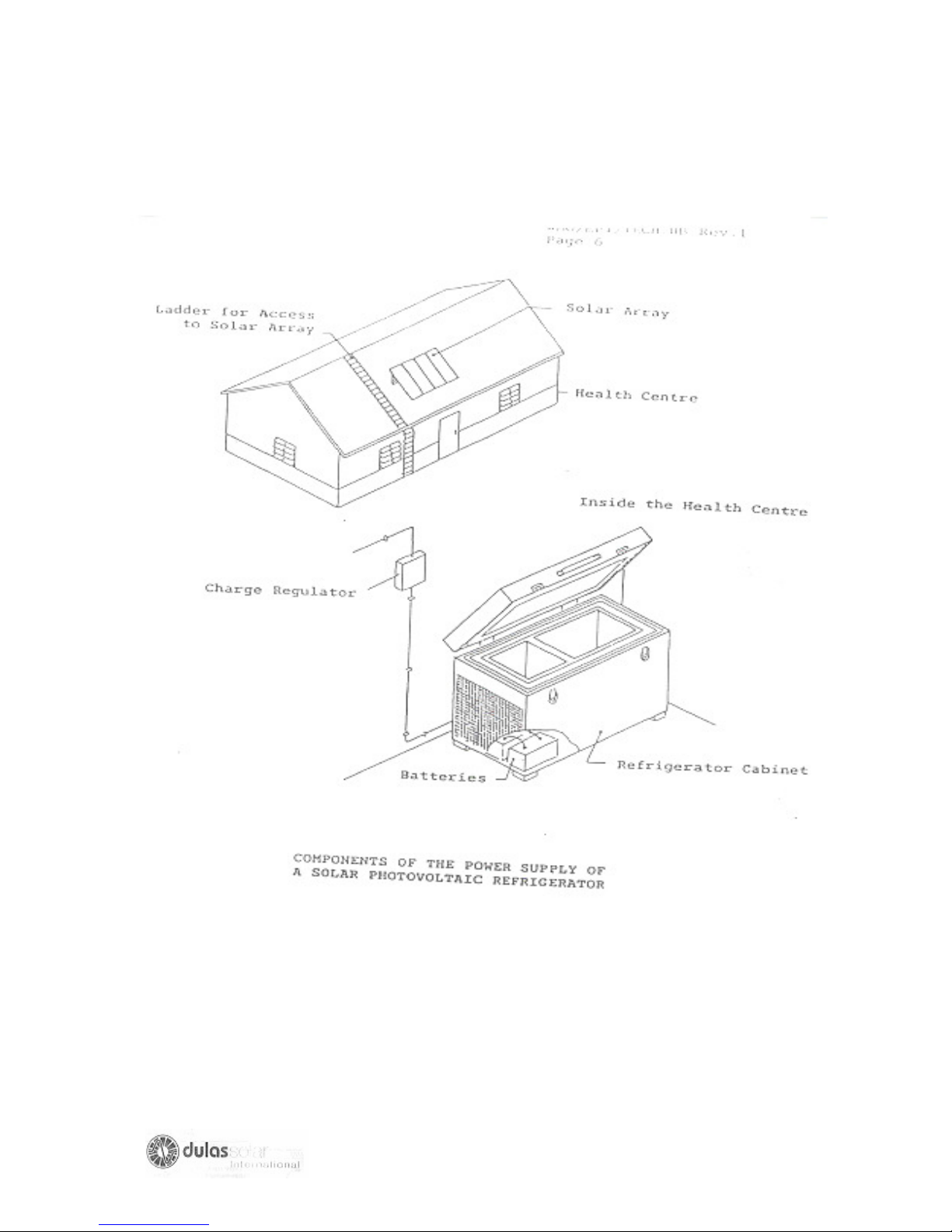
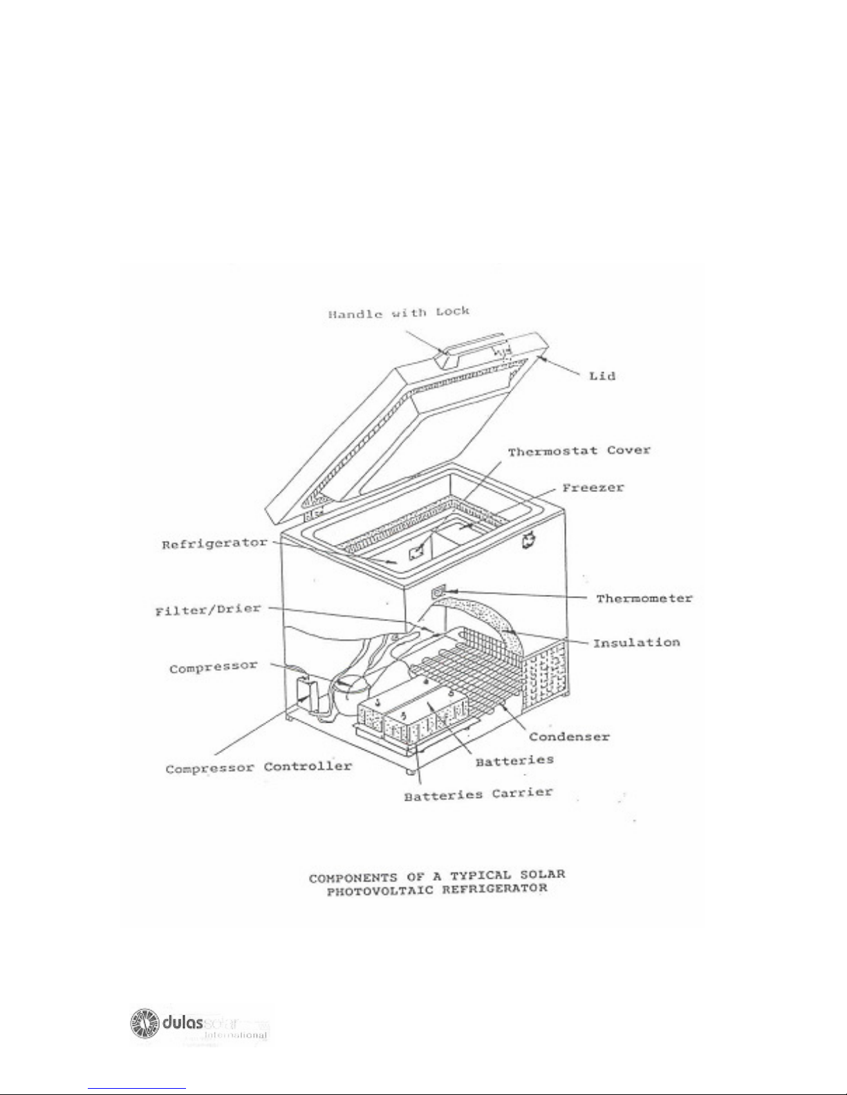
(a) Before starting service or repair work make sure you are familiar with the
location of the components of the solar refrigerator (see pages 37& 38)
(b) Layouts of components in some commonly used solar refrigerators are shown
in Annex1.Make sure you also have the manufacturers maintenance and repair
manual for the refrigerator.
(c) REMEMBER
There is a risk of electric shock from the solar array. There is the risk of acid burn or
explosion from batteries.
ENSURE THAT YOU TAKE THE SAFETY PRECAUTIONS DESCRIBED ON PAGE
34 & 36
37
Page 38
38
Page 39
39
Page 40
B: HOW TO MEASURE
1. TEMPEARTURE
Temperature is measured with thermometers. There are many different types of
thermometers. The choice of thermometer should depend upon the degree of
accuracy, the reliability, the response rate, the temperature range required and
budget available.
1.1 Refrigerator and freezer temperature
Temperatures are usually measured in the refrigerator and freezer compartments of
photovoltaic refrigerators with low –cost, simple low precision bi-metal thermometers.
This type of thermometer is robust, stable and simple to read.
It is easy to check the accuracy of a bi-metal thermometer by removing it from the
freezer or refrigerator compartment and placing it alongside another thermometer for
several minutes at room temperature. If the thermometer gives the same reading;
then most likely they are reading correctly.
Thermometers used in the compartments of refrigerators frequently have red/and/or
green ranges marked on the scale, which indicates the correct temperature range at
which the compartments should be operating.
The procedure is to read the temperature directly from the scale, which should be
marked in degree Centigrade (0 C).
REMEMBER: THE VACCINE COMPARTMENT OF A REFRIGERATOR SHOULD
ALWAYS BE BETWEEN 00C AND 80C.
40
Page 41
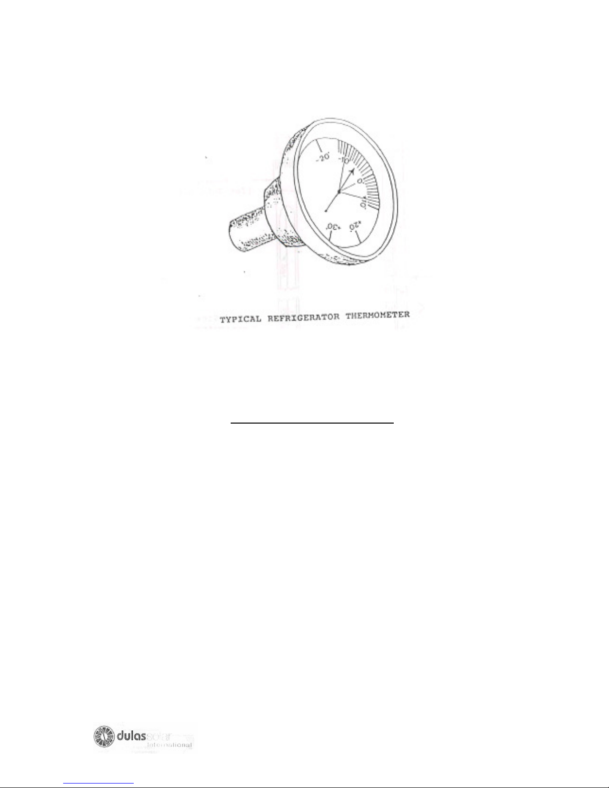
TYPICAL REFRIGERATOR THERMOMETER
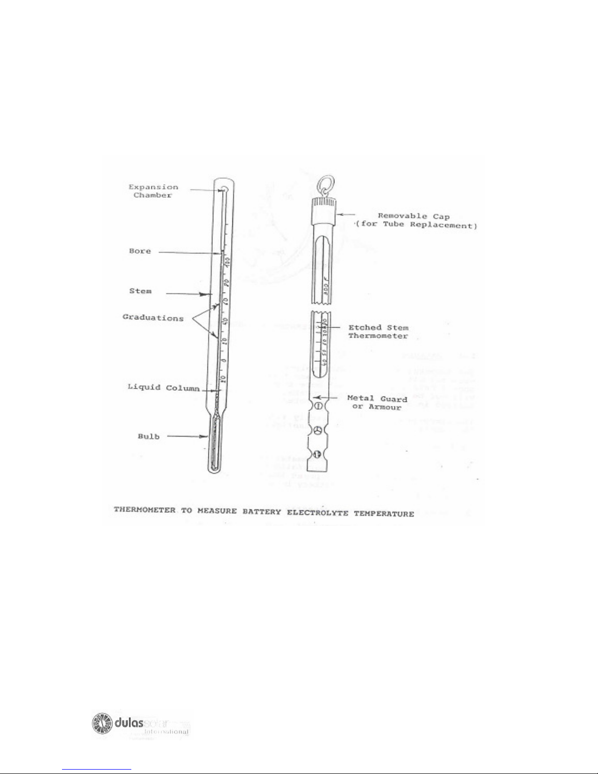
BATTERY TEMPERATURE
The temperature of the electrolyte in the battery cells must be measured with
mercury in glass thermometer. The thermometer should have a range of not more
than 00C to 80C;otherwise it will not be sufficiently accurate. The thermometer should
be encased in a metal shell to protect it from breakage.
The temperature is read directly from the scale on the thermometer and should be in
Centigrade (0 C).
To take a measurement:
1. Put the bulb of the thermometer in the electrolyte and hold it in the electrolyte
carefully for about 30 seconds. (You must be careful not to press the
thermometer bulb against the metal plates in the battery because they are
delicate and easily damaged.)
2. Read the temperature directly from the thermometer.
3. After using the thermometer, wash it thoroughly in cool water. Do not use hot
water, you may break the thermometer.
41
Page 42
42
Page 43

2. ELECTRICITY
2.1 General
When doing faultfinding and repairs on photovoltaic refrigeral systems, it is
necessary to measure the voltage, current and resistance at various points in the
circuit.
The type of voltage measured is DC (direct current) volts and no AC (Alternating
current) volts as is normally observed in the electrical supply of houses.
The type of current measured is DC (Direct current) amps and no AC (Alternating
current) amps as is normally observed in the electrical supply of houses.
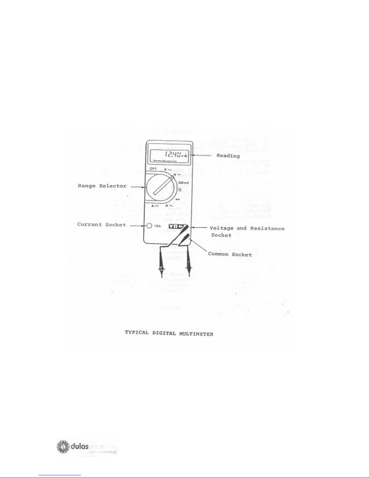
The instrument that is found in the UNIPAC maintenance kit supplied to repair
technicians is a millimeter. This millimeter has the capacity to measure DC volts, AC
volts, resistance, AC current and DC current. It has a digital display and when set
correctly is very easy to read. The accuracy of the instrument provided in the
maintenance kit is sufficient for all faults finding and repair tasks you may need to do.
There are three basic rules, which MUST BE OBSERVED when measure in
electricity.
1. Voltage is always measured by putting the probes of the millimeter between
(across) two points in the circuit. The meter is connected in PARALLEL with
the circuit, which you are measuring.
2. Current is always measured by disconnecting the two points where you wish
to measure current and putting the probe between the two disconnected
points of the circuit. The meter is connected in SERIES with the circuit you are
measuring.
3. Resistance can only be measured when the power has been removed from
the circuit.
43
Page 44
44
Page 45
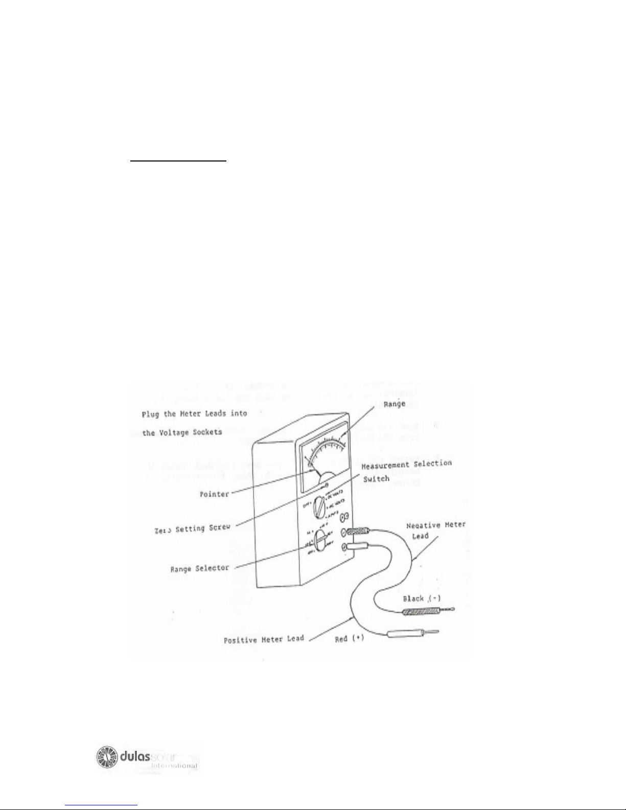
2.2 Measuring Voltage
Use a millimeter or DC Voltmeter to measure DC voltage in the following manner:
1. Set the millimeter to measure DC voltage
2. Set the range on the meter so that it included the voltage that you expect to
measure. For example, if you expect that the voltage you are going to
measure will be about 12 V, set the range to 0-20V.
3. Plug the meter leads into the meter sockets. Make sure that the negative
(black or -) lead goes into the negative (or ‘common’) socket, and that the
positive (red or +) lead goes into the positive socket.
45
Page 46

4. Make sure that the meter is switched ON and that it has charged batteries
inside. Some types of millimeter are switched on automatically when you turn
the measurement selection knob.
5. (a) If the meter is an analogue type as shown on this page, make sure that the
needle points to 0 volts when the metal tips of the metal leads are not
touching anything. If the needle does not point to 0 volt, adjust zero setting
screw until it does. Look at the scale with straight in front of you so that
you can read it accurately. Do not look from an angle.
(b) If a meter is a digital type, make sure it read 0.0 volts when you touch the
meter leads together.
6. Touch the metal tips of the meter leads to the electric terminals across which
you want to measure the voltage. Be careful not to short-circuit the terminals
by touching both the terminals with the same probe. If you short-circuit the
terminal large currents may flow and cause damage to components.
7. Read the voltage from the meter. Make sure that you read from the correct
range on the scale.
8. SWITCH THE METER OFF after you have finished taking the measurement.
If you do not do this, the batteries may become drained.
46
Page 47

2.3 MEASURING CURRENTS
2.3.1 Use a millimeter or DC ammeter to measure current in the following manner:
1. Set the millimeter to measure current. The setting on the selection knob may
be labeled “current”, ”amperes”, ”amps” or just “A”.
2. Set the range so that it included the current that you expect to measure. If you
expect current to be about 5A,set the range to 0-10 A.
3. Plug the meter leads into the correct sockets in the meter. Make sure that the
negative (black or -) lead goes into the negative (or “common”) socket and
that the positive (red or +) leads goes into the current (A) socket.
4. Make sure that the meter is switched ON and that it has batteries inside.
Some types of meter are switched ON automatically when you turn the
measurement selection knob.
5. If the meter is an analogue meter as shown above make sure that the needle
points to 0 amps when the metal tips of thermometer leads are not touching
anything. If the needle does not point at 0 amps, adjust zero setting screw
until it does. Look at the scale with it straight in front of you so that you can
read it accurately. Do not look from the angle.
6. Switch OFF the circuit. Disconnect at one terminal the wire through which you
want to measure the current.
7. If you have disconnected the positive wire, connect it to the black (common)
meter lead. If you disconnected the negative wire, connect it to the red lead.
To make the connection use a crocodile clip to hold the lead and the wire
together.
8. Touch the metal tip of the other metal lead to the terminal from which you
disconnected the wire.
9. Switch ON the circuit. Be careful not to make a short-circuit between the
terminals by accidentally touching both terminals.
10. Note down the reading. Make sure you read from the correct range on the
Scale if the meter is an analogue ammeter.
47
Page 48
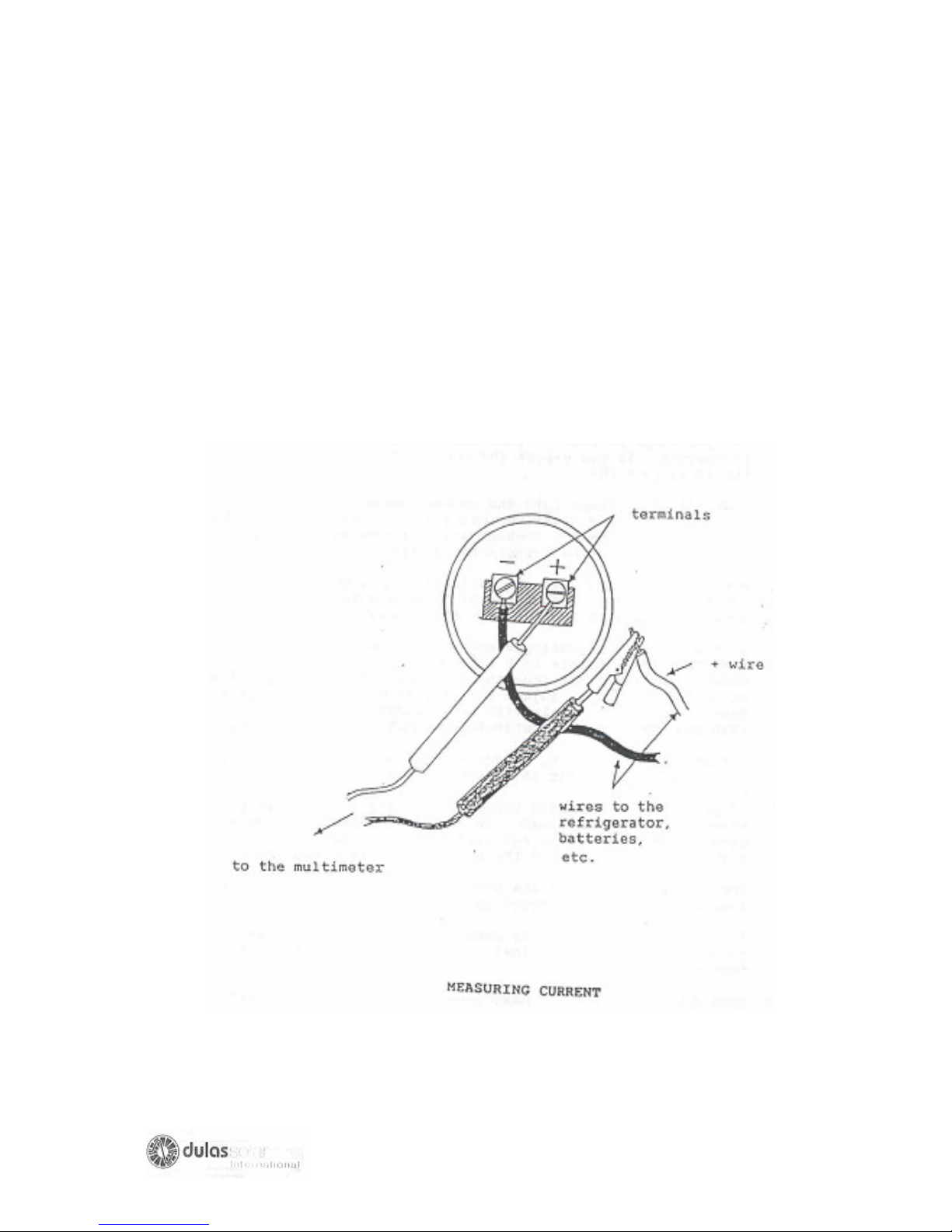
11. SWITCH THE METER OFF after you have finished taking the
measurement so that you do not drain the batteries.
12. SWITCH OFF the circuit and reconnect the wire to its terminal.
13. Switch back ON the circuit.
48
Page 49

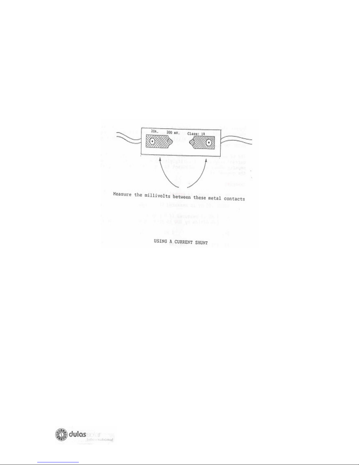
2.3.2 Using a current shunt with a millimeter or milivolt meter to measure
current.
1. Switch OFF the system. Disconnect the wire at the terminal where you want
to measure the current.
2. Select a current range that included the current yu expect to measure.
Connect the shunt between the disconnected wire and the terminal and
connect the probes of the millimeter to each terminal of the current shunt.
3. Select the mili-volt range on the millimeter which includes the mili-volt range
identified on the current shunt, and proceed to measure the mili-volt across
the current shunt as shown below.
4. The value read on the meter in mili-volts is converted to current (amperes) by
multiplying this number by the number of amperes, which are equivalent to 1
mili-volt as indicated on current shunt.
Example:
Current shunt is marked 20 A. 200 mV
Hence 200 Mv is measured if 20 Amps is flowing the wire so, 1 mV is
measured if 20 Amps is flowing in the wire (We divide by 200 to find
the equivalent of 1 mV).
So, 1MV= 0.1 Amp
If, for example the reading on millimeter is 55 mV
Across the shunt connections we have 55 mV (mili-volts)
Therefore in the circuit we have 55 * 0.1 Amps= 5.5 Amp
Current in circuit= 5.5 Amps
49
Page 50
50
Page 51

3. RESISTANCE
In fault finding and repairs of photovoltaic refrigerator systems it is necessary to
measure the electrical resistance of the compressor windings and to determine if
these windings are adequately insulated. The millimeter provided in the UNIPAC
maintenance kit (or any other millimeter) is adequate for these tasks if the following
procedure is observed.
1. Switch OFF the refrigerator.
2. Disconnect the wires from the positive terminal of the battery.
3. Set the millimeter to measure resistance.
4. (a) If you want to measure small values of resistance, set the range on the
millimeter to ‘one ohm’ (which may be indicated 1)
(b) If you want to measure high values of resistance set the range to 100,000
ohms or the largest range of resistance on your millimeter.
5. Switch ON the meter, plug in the meter leads to the correct sockets in the meter,
and hold the tips of the probes together.
6. If you have an analogue meter adjust the meter so that the resistance between
the probes reads zero. If you are unable to adjust the meter so that it reads zero,
this means that the batteries in the meter are discharged and should be changed.
7. Holds the probes between the two points in the circuit where you want to measure
resistance.
8. Read the resistance value directly on the meter if you have a digital meter, or on
the appropriate scale if you have an analogue meter.
9. SWITCH THE TIMER METER OFF when you have finished.
51
Page 52
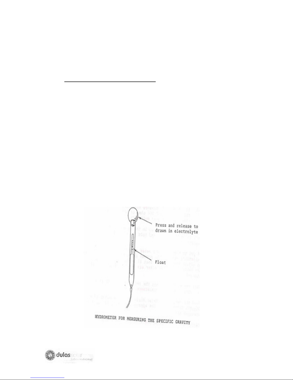
4: STATE OF CHARGE OF BATTERIES
The amount of energy stored in a battery at any time is called the “State of Charge”.
The “State of Charge” can be approximately estimated by measuring the voltage
across the battery terminals when battery is being discharged under know conditions
of current and temperature and is the only way to measure the State of Charge of
sealed batteries.
The State of Charge of lead-acid batteries that are not sealed can also be
determined by measuring the specific gravity of the electrolyte (the acid and water
mixture in the battery) and the temperature of the battery. This is the most practical
way to measure the state of charge of batteries, which are not sealed.
The following procedure explains how to do this:
1. Top up the battery with clean distilled water to the maximum level indicated on
the battery.
2. Leave the battery for one hour to allow the acid and water to mix.
52
Page 53

3. Insert the hydrometer into the electrolyte in a cell of the battery, squeeze the
rubber bulb, and draw enough electrolyte into the hydrometer to make the
indicator float freely.
4. Record the specific gravity reading as indicated by the float and adjacent
scale.
5. Return the electrolyte to the small cell in the battery being careful not to spill it.
6. Insert a thermometer (mercury in glass type) into the battery so that the bulb
of the thermometer is covered in electrolyte but not touching the battery
plates. Wait until the temperature shown has stabilized and record the
electrolyte temperature.
7. Using the table below, which shows the temperature correction to specific
gravity, record the correction value.
Temperature Correction to Specific
Gravity Readings (to 150 C)
Electrolyte Temperature 0C Correction to specific Gravity
55 +0.028
50 +0.024
45 +0.021
40 +0.017
35 +0.014
30 +0.010
25 +0.007
20 +0.003
15 0.000
10 -0.003
5 -0.007
0 -0.010
TEMPERATURE CORRECTION TABLE
Example
For 30 degrees centigrade the correction is +. 010
53
Page 54
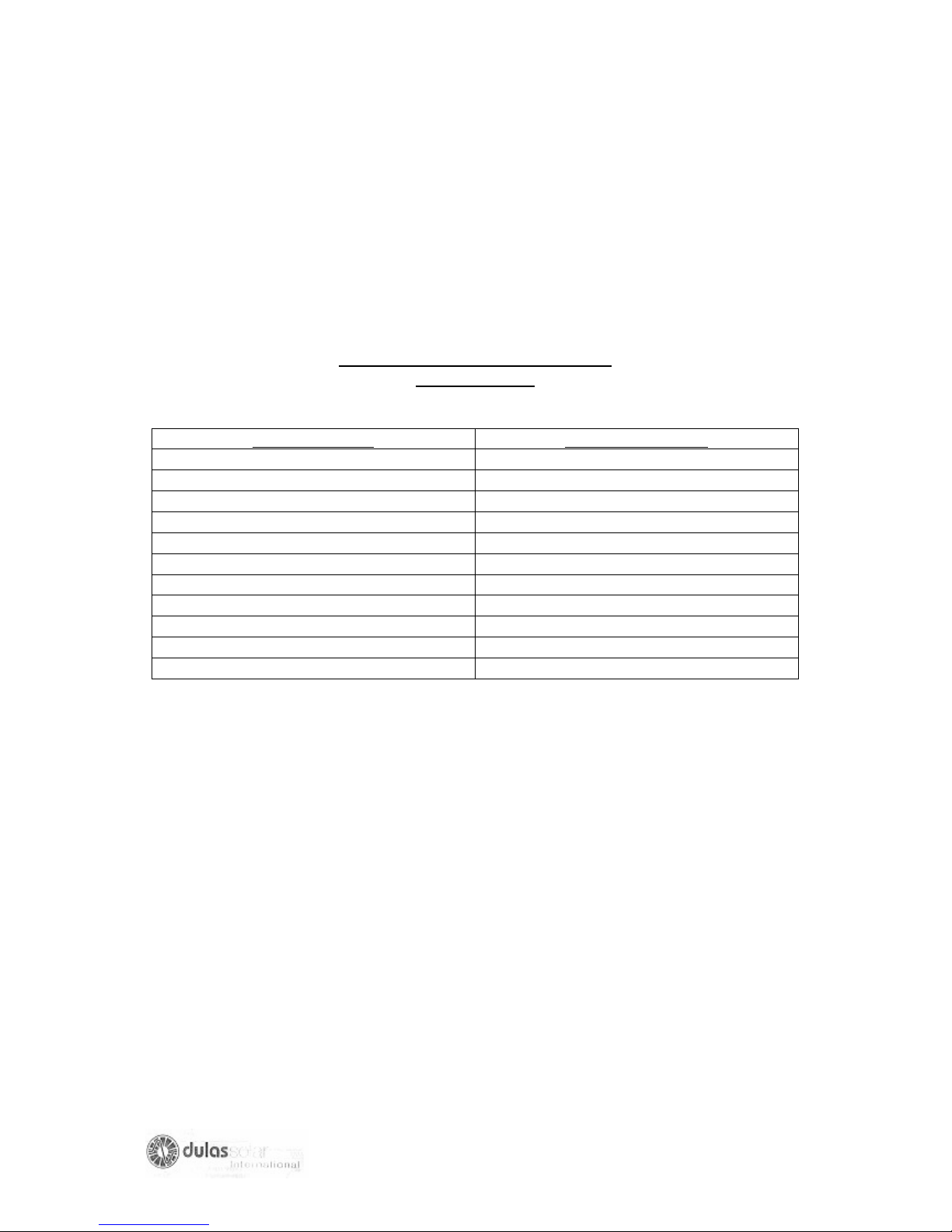
Add this value to the reading obtained from the hydrometer.
This answer gives the specific gravity of the electrolyte if at 15 degrees Centigrade.
8. Convert the specific gravity into a measurement of the States of charge by
looking at the table below.
Specific gravity at 15 degrees C Vs
State of charge
Specific Gravity State of Charge %
1.225 100
1.216 90
1.207 80
1.198 70
1.189 60
1.180 50
1.171 40
1.162 30
1.153 20
1.144 10
1.135 0
STATE OF CHARGE TABLE
Example:
A specific gravity of 1.202 corresponds to a state of charge of between 70 and
80 %.
54
Page 55

5: TILT AND DIRECTION OF PHOTOVOLTAIC ARRAY
5.1 General
The tilt of a photovoltaic array is the angle created between the surface of the array
and the horizontal.
The tilt should be approximately equal to the latitude of the site, except in case
where the latitude is less than 50 either North or South, in which case the tilt should
be maintained at 50.
A line normal to the surface of the array points out the direction of a photovoltaic
array.
A photovoltaic array should always slope towards the South when mounted in the
Northern hemisphere and always slope towards the North when mounted in the
Southern hemisphere.
For photovoltaic refrigerator installations, neither the tilt or direction needs to be
measured with any great accuracy, but both should be correct within 10 degrees.
Array tilt may be measured with an inclinometer, which is an instrument designed
especially to measure slope or a spirit level and ruler or tape measure and some
simple calculations. These methods are described in the INSTALLATION
HANDBOOK for Photovoltaic Refrigerators.
The best method however is to use a TEMPLATE (triangle) and SPIRIT LEVEL as
described on the next page.
Array direction may be measured with a compass.
55
Page 56
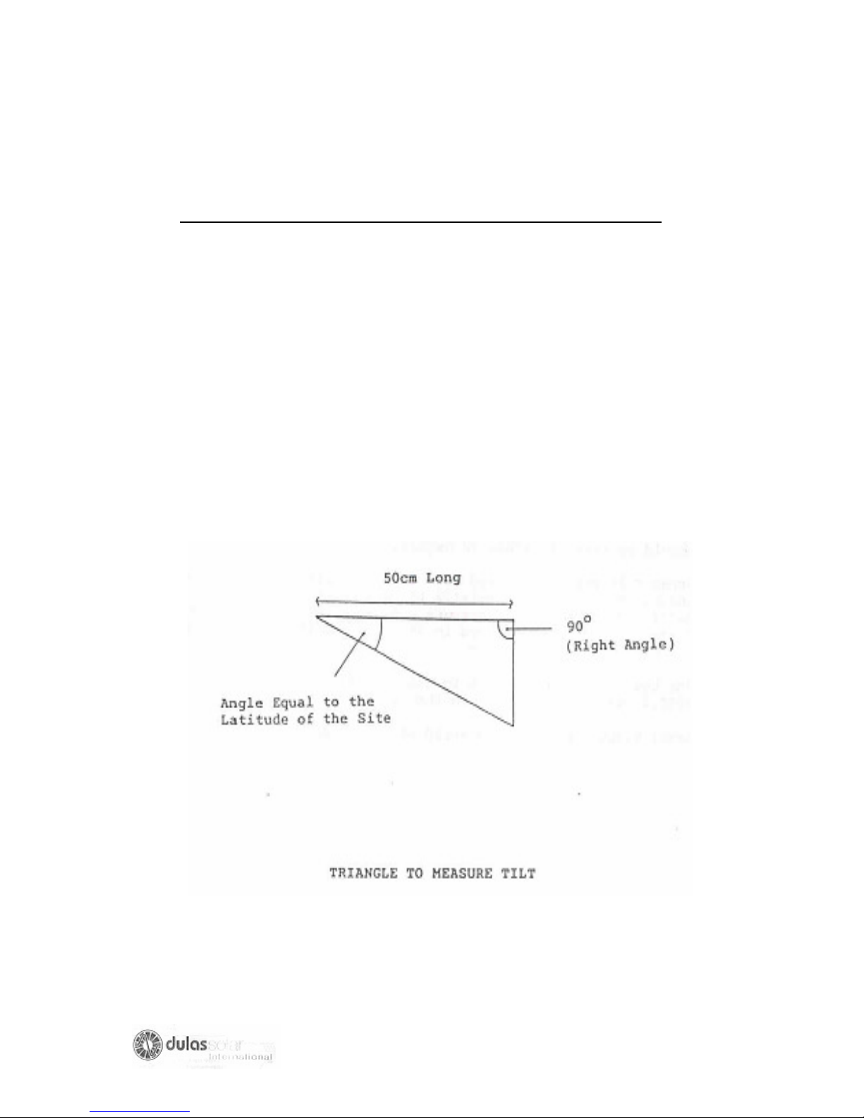
5.2 HOW TO MEASURE TILT WITH A TEMPLATE AND SPIRIT LEVEL
1. If you do not already know, find out the approximate latitude of the place
where the refrigerator is installed.
2. Cut out a triangle from cardboard if you do not plan to use it often, or from
wood if you have several solar arrays to check. (DO NOT MAKE IT FROM
METAL). The triangle should be have:
- one side 50 cms long
- one angle of 90 degrees, and
- one angle equal to the latitude where the refrigerator is installed.
56
Page 57
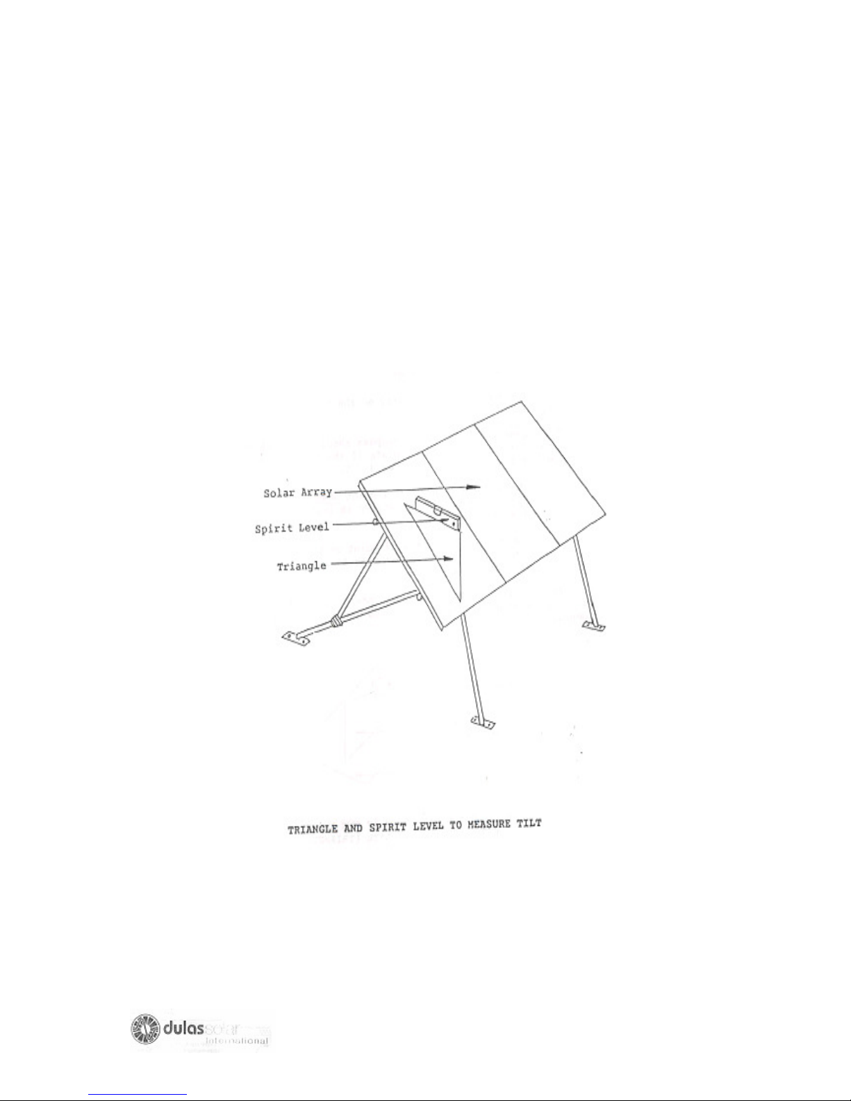
3. Place the triangle on the surface of the array so that it is parallel to the sloping
sided of the array and so that the angle, which is equal to the latitude, points
away from the equator.
4. Place a spirit level on the upper edge of the triangle. If the bubble in the level
indicator shows that it is level, then the photovoltaic array is set an angle,
which is equal to the latitude.
57
Page 58
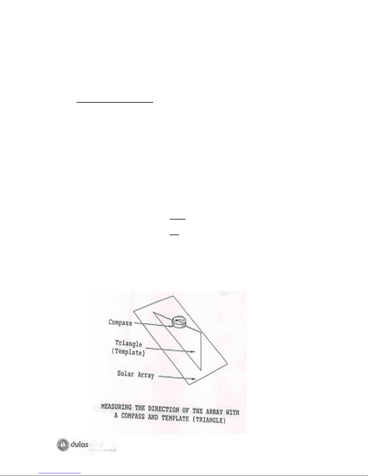
5.3 How to measure direction
The only practical method to measure direction of the array with sufficient accuracy
is with a compass. The procedure is as follows:
1. Place the cardboard or wooden template, which you used to check the tilt of the
array on the surface of a module so that it is parallel to the sloping sides of the
module and so that the angle on the template, which is equal to the latitude, points
away from the equator.
2. Place the compass horizontally on the top edge of the template.
3. The magnetic needle on the compass should point along the line of the edge of
the template if the array slopes (faces) towards the equator, as it should. Also note
that:
- The magnetic needle will point down the slope of the panel. If your refrigerator
is installed in the southern hemisphere.
- The magnetic needle will point up the slope of the panel If your refrigerator is
installation is in the Northern hemisphere.
4. The direction of the array on lt needs to be positioned to within an accuracy of
about 100 based on measurements with a compass.
58
Page 59
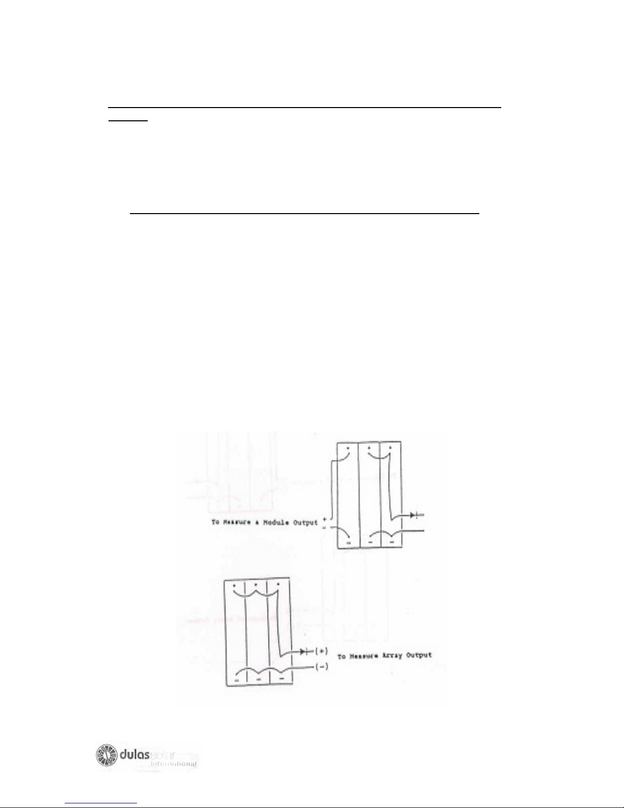
6: OPEN AND SHORT CIRCUIT MEASUREMENTS ON THE PHOTOVOLTAIC
ARRAY
Two simple measurements are possible to show whether a photovoltaic array is
prating correctly. These are the measurement of SHORT CIRCUIT CURRENT AND
OPEN CIRCUIT VOLTAGE.
Measurements are made as follows:
6.1 Using a millimeter or voltmeter to measure open-circuit voltage (Voc)
1. To test the solar array or one of the solar module in the array, you need to be
able to measure the open-circuit voltage (Voc).
2. Measure Voc at around 12 noon on a very sunny day.
3. Voc is the voltage across the two output terminals when no electrical current
is flowing. So you must disconnect one wire from the terminals. If you are
measuring Voc for the solar array, disconnect one solar array output wire from
the terminal box .If you are measuring Voc for one of the solar modules,
disconnect the module from the solar array at the module box.
4. After you have disconnected the output wires, measure the voltage across
solar array or module output terminals.
5. Reconnect the wires to the correct terminals after you have finished.
59
Page 60
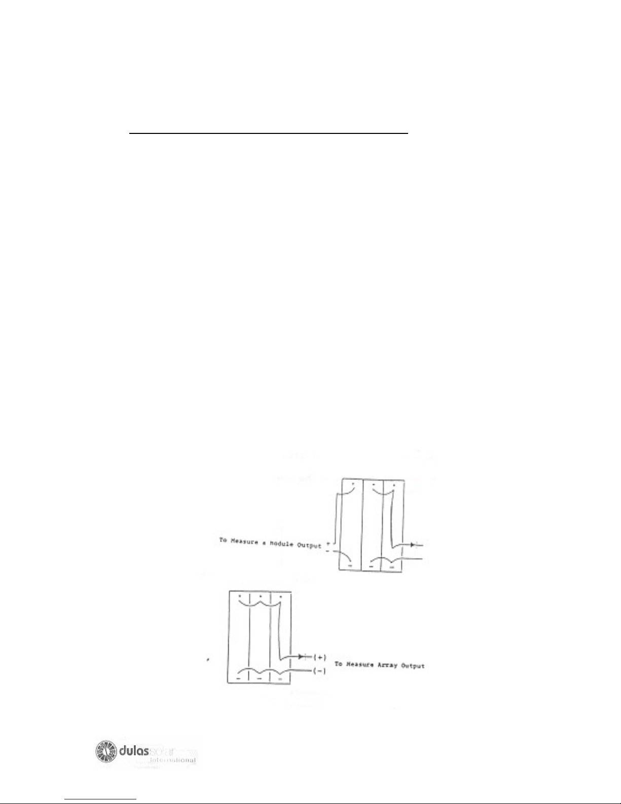
6.2 Using a millimeter or ammeter short-circuit current (Isc)
1. To test solar array or one of the modules you need to be able to measure the
short-circuit current (Isc).
2. Measure Isc around 12 noon on a very clear sunny days and during a long
period of uninterrupted sunshine (no clouds).
3. Isc is the electrical current flowing between the two output terminals when
they are short-circuited by the millimeter or a shunt. You must disconnect one
output wire from the terminals when you make this measurement.
- If you are measuring Isc of the solar array disconnect a solar array
output wire from the array junction box.
- If you are measuring Isc of one of the solar modules disconnect the
module from the solar array at the module junction box.
4. After you have disconnected the output wires, measure the current between
the solar array (or module) output terminals.
5. Reconnect the output wires to the correct terminals after you have finished.
60
Page 61

C: MAINTENANCE AND SERVICE TASKS
C.1 Introduction
The service tasks described here should all be done every time you visit a solar
refrigerator.
BEFORE YOU START THE SERVICE TASKS DO THE FOLLOWING:
a) Check that the temperature of the refrigerator is normal (between+00 C and +80C)
before you start the service.
b) Ask person in charge of the refrigerator if there have been problems with it.
Inspect the logbook and temperature record sheets to see if a problem is
indicated.
c) Enter into the refrigerator log books the date of your visit, and at the end of your
visit write down the tasks done and measurements taken.
WHEN YOU FINISH THE SERVICE TASKS:
a) Check that the temperature of the refrigerator is normal
b) Check all components to ensure the installation is safe and secure. There should
be no loss components or bare wires and the batteries should be in a secure
place out of reach of children.
61
Page 62

C.2. Cleaning the Solar Array
You should clean the surface of the solar array whenever you visit the health post.
(a) Clean the array in the early morning or in the evening when it is not in strong
sunlight.
(b) If the solar array is on the roof you will need a ladder to reach it. Be very
careful when working on the roof. Check that access to the array is secure
and safe for the user. If not make it safe.
(c) Use a clean, soft cloth wetted with water.
(d) Wipe the surface of the solar array gently, starting at the highest point and
working down to the lowest point.
(e) Do not stand on the solar array, or lean heavily on it, as this may cause
damage.
(f) Make sure that the person in charge of the refrigerator knows that he/she
should clean the solar array every week.
62
Page 63
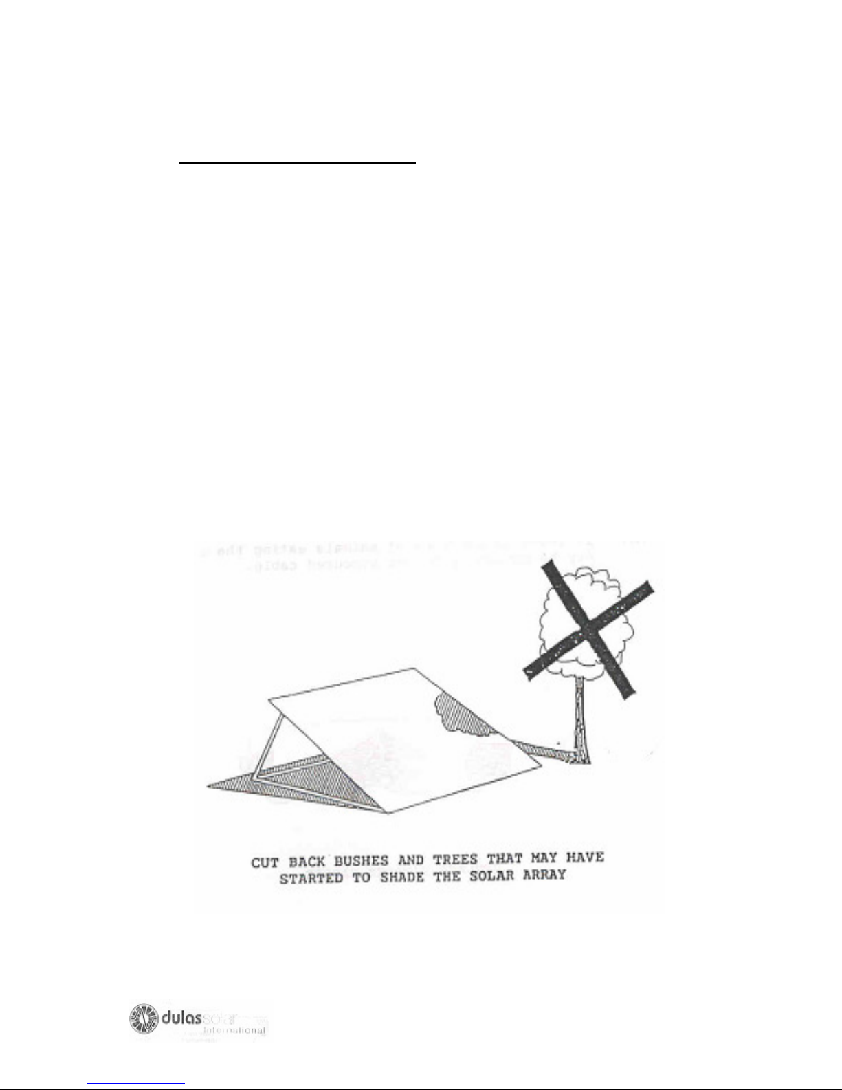
C.3 Preventing Solar Array Shadowing
The solar array will not work properly if it is shaded during the day.
(a) Check that the solar array is not shaded on any part. This should be checked
at approximately 8.00 a.m., 12.00 noon, and 4.00 p.m. on the day that you
visit the health centre.
(b) Cut back bushes and trees that may start to shade the solar array between
8.00 a.m. and 4.00 p.m. Trees and bushes which cause shading only before
8.00 a.m. or after 4.00 p.m. need not to be cut down.
(c) Make sure that nobody has put anything in front of the solar array that may
block the sunshine falling on it.
(d) If new building cause shadows to fall on the array it may be necessary to
move the array. Consult the person in charge of the refrigerator as to where it
may be moved and make arrangements to do this.
63
Page 64
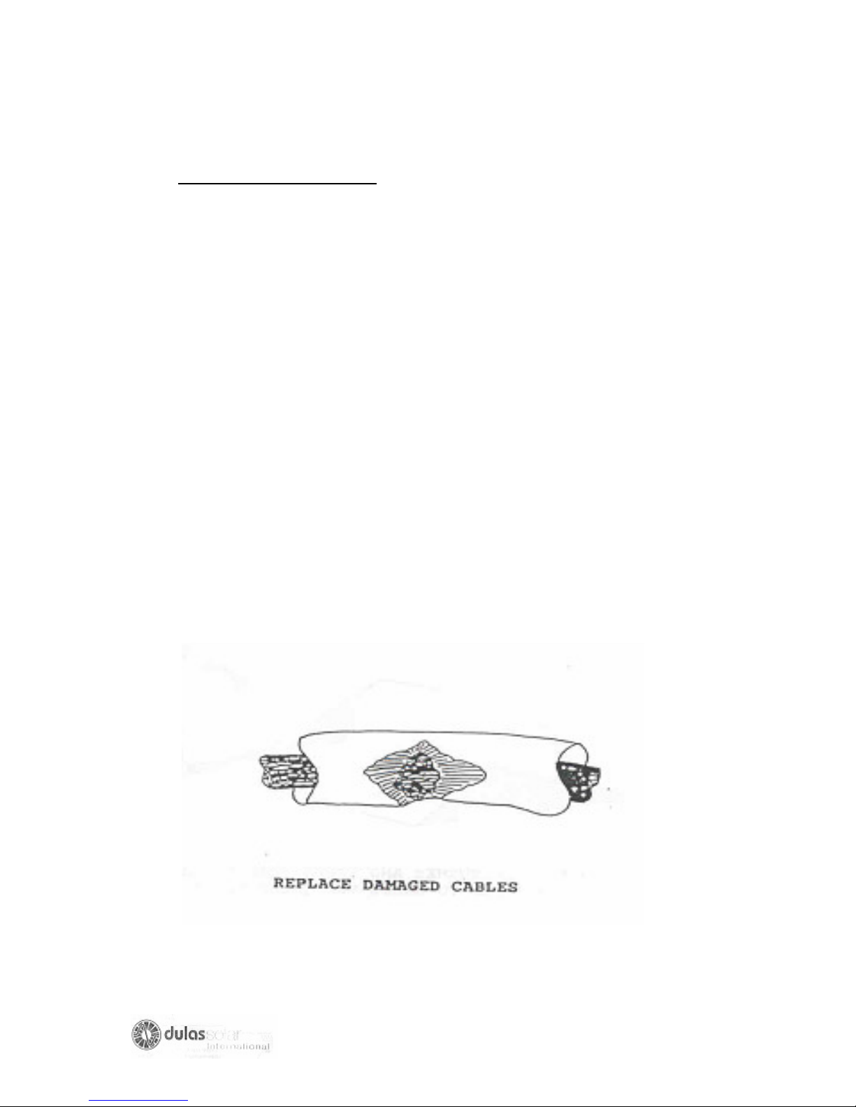
C.4 Inspection of Electric Cables
Electric cables run between the charge regulator and the solar array, the batteries,
and the refrigerator. These cables should be inspected every time you visit an
installation to make sure that they are in good condition.
(a) Check the connections on the cables, which go to the battery terminals, the
solar array terminals, the refrigerator terminals (on the compressor controller
and on the refrigerator socket), and the charges regulator terminals strip. The
connections should be clean and tight. If they are loose, tighten them. If they
are dirty, take them off and clean them with a wire brush before connecting
them tightly.
(b) Follow each cable to its end, wherever possible. Look for the following types
of damage: the cable has been cut, the insulation is worn or the insulation has
been eaten away leaving the metal inside showing.
(c) If the cable is damaged, it must be replaced. Follow the instructions on page
83 to replace the cable.
(d) If there is evidence of animals eating the cables it may be necessary to use
armored cable.
64
Page 65

C.5 Checking the Performance of the Solar Array
NOTE 1: It is only necessary to check the performance of the solar array if you
believe there may be problem with it. For example if the user reports or the
daily record sheets indicate that the “Do not freeze Ice Packs” or
“Refrigerator Disconnected” indicator lights are often lit.
NOTE 2: You should only check the solar array on a day when the sky is clear (no
clouds) and at about midday.
NOTE 3: Before disconnecting any cables label them so you know where to
reconnect them.
1. Clean the solar array (see page 54)
2. Check that the solar array is not shaded (see page 54)
3. Disconnect from the solar array, the array cable that leads to the charge
regulator.
4. Measure the short circuit current of the solar array (see page 52)
5. Measure the open circuit voltage of the solar array (see page 51). It should be
17-20 volts for a 12-volt system.
6. Disconnect one module from the array and measure the short circuit current
of the module (see page 52)
For 12 volt systems the short circuit current in the solar array should
approximately be equal to the to the current in a module multiplied by the
number of modules (to within 15 %). (For example if the short circuit of one
module is 2.5 Amps and there are four modules in the array then the solar
array short circuit should be approximately 2.5 * 4 =10 Amps.
7. If the array current and voltage do appear correct reconnect the module and
array cable.
8. If the solar array short-circuit current or open current voltage does not appear
correct then there may be a fault with a module or the way the modules are
connected together. Refer to faultfinding task D7 on page 58 to find out what
action is required to repair the fault.
65
Page 66
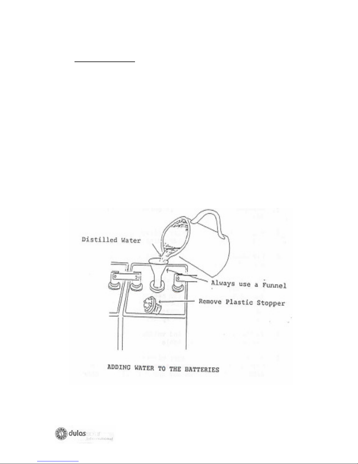
C.6 Battery Maintenance
Warning: ● KEEP NAKED FLAMES AWAY FROM BATTERIES AS
EXPLOSIVE GASES MAY BE PRESENT.
● THE LIQUID IN BATTERIES IS CORROSIVE. KEEP OUT OF SKIN
AND AWAY FROM EYES.AVOID CONTACT WITH CLOTHES.
(a) Switch the refrigerator OFF.
(b) Disconnect the battery cables at the battery labeling the cables clearly so you
know where to reconnect them.
(c) Measure, and note in the logbook, the voltage of each battery and the of the
batteries combined.
(d) If the batteries are not sealed, they will have plastic stoppers in a row on the
top. Remove each stopper one by one and see if the metal plates inside are
covered by liquid. If the tops of the metal plates are above the liquid level, add
distilled water until they are completely covered or to the level indicated in the
battery. Replace the stopper. Do this for every compartment in each battery.
66
Page 67
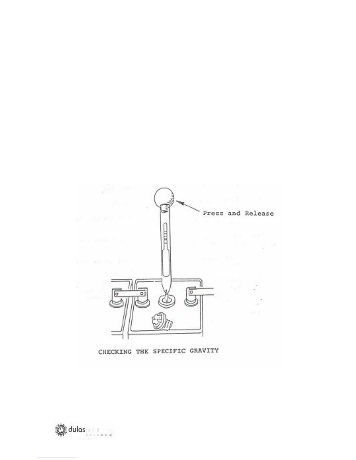
(e) If there are non-sealed batteries, measure and note in the log book the
electrolyte specific gravities and temperatures and determine the state of
charge of the batteries (see page no 46)
(f) Check the ages of the batteries from the logbook or from marks on them. If
they are more than 5 years old, order and fit a replacement as soon as
possible.
(g) Check the wiring connections to the batteries. If the wiring connections are
loose, tighten them. If the connections are very dirty or corroded, loosen them
and clean them with a wire brush before tightening them again.
(h) Apply petroleum greases to the terminals.
(i) Reconnect the battery cables ensuring they are in the correct position.
(j) Switch ON the refrigerator.
67
Page 68

C.7 Defrosting the Refrigerator
If the ice in the freezer compartment of the refrigerator is more than 5 mm (1/4 inch)
thick, defrost the refrigerator.
(a) Move the vaccine into another refrigerator or store it in a cold box with
ice-packs.
(b) Switch the refrigerator OFF.
(c) Open the Lid of door of the refrigerator and freezer compartment.
(d) As soon as it is possible to remove ice with your fingers, do so. Do not
remove ice with knives or other sharp objects.
(e) Wipe the freezer compartment dry after all the ice has been removed.
(f) Clean the refrigerator inside with soap and water, and then dry it
carefully. Never use scouring powder, steel wool or abrasive cleaners.
Remember to clean the lis or door-sealing gasket and put some talcum
powder on it to prevent it sticking to the lid.
(g) Switch the refrigerator back ON.
(h) Wait until the inside temperature has fallen to between 00Cand +80C.
(i) Put the vaccine back inside and remember to close the lid/door again.
(j) Defrosting must be carried out as quickly as possible to prevent
damage to the vaccine.
(k) Tell the person in charge of the refrigerator to defrost it regularly. It
should be defrosted when the ice in the freezer compartment becomes
more than 5 mm (1/4 inch) thick.
68
Page 69
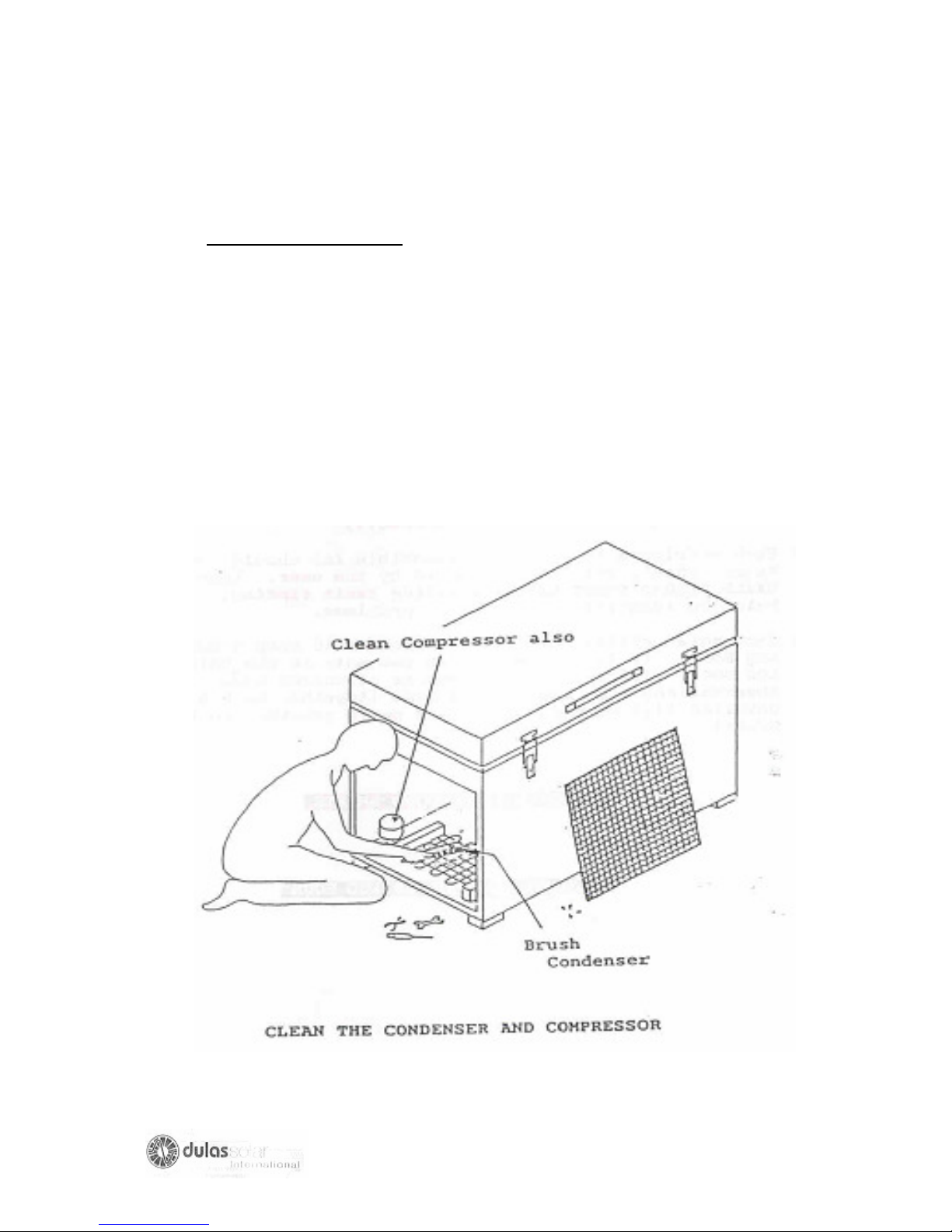
C.8 Cleaning the Refrigerator
(a) Switch off the refrigerator.
(b) Clean the surfaces of the condenser and compressor using a soft brush. The
condenser and compressor must be clean or the refrigerator will not work
properly.
(c) If the condenser is fan-assisted make sure the fan rotates freely and brush dirt
away from the fan and fan motor.
(d) Switch the refrigerator ON again.
(e) Wipe cleans the outside of the refrigerator using soap and water.
69
Page 70
PART 3: FAULT FINDING AND REPAIR
A.1. INTRODUCTION
(a) Before starting the fault finding, make sure you are familiar with the location of
the components of a solar refrigerator.
A typical solar refrigerator is layout is shown on pages 37 & 38
Annex 1 shows the location of components on the most commonly used solar
refrigerator.
(b) Each installed solar refrigerator will have a USER who was trained by the
installation technician on how to operate and care for the refrigerator. It is your
responsibility when at a health centre to make sure that the user is operating and
maintaining the refrigerator correctly.
(c) Each refrigerator you are responsible for should have a Daily Record Sheet
before starting faultfinding. It may help you identify the source of problem.
(d) Each solar refrigerator technicians should keep a maintenance Log Book. It is
important that you note in the maintenance log book, visits to sites, results of
checks made, observations made and repairs (together with fully detailed list of
parts used and parts provided to the users)
CHECK DAILY RECORD SHEETS
FILL IN MAINTENANCE LOG BOOK
70
Page 71

B: HOW TO FIND FAULT
The instructions in this part of the handbook advise you on what to do if the
refrigerator compartments are not maintaining the correct internal temperatures. The
temperatures should be more than 00C and less than 80C in the refrigerator
compartments, and less than 00C in the freezer compartment.
If the temperatures are not within these ranges you should follow this faultfinding
procedure. FOLLOW THIS PROCEDURE CAREFULLY.DO NOT TRY TO TAKE
SHORT CUTS. DO NOT MISS OUT ANY TASKS IN THE PROCEDURE.
B.1 Determine the Symptoms
Identify the symptoms of the fault by finding out if:
(a) The refrigerator is too warm (above 80C) and the compressor is NOT running.
You may determine if the compressor is running by:
- Listening for the motor noise from the compressor, (but make sure that
it is not the noise of the fan, if fitted),
- Touching the compressor to see if it is vibrating, and
- Touching the compressor to see if it is hot.
(b) The refrigerator is too warm (above 80C) and the compressor is running at
times.
(c) The refrigerator is too cold.
B.2. Carry out Preliminary Checks
These preliminary checks are to be done in order to verify that the user had
performed all of the user checks and tasks.
IT IS IMPORTANT that:
(a) You be sure that you have correctly identified the symptoms of the fault.
(b) You always start with the first step listed under each symptom and proceed in
order through all the steps.
(c) If after doing ALL the CHECKS and ACTIONS, the refrigerator is still not
working properly you move the vaccine into another refrigerator or cold box,
and
(d) PERFORM THE CHECKS AND ACTIONS (LISTED ON THE NEXT PAGE)
UNDER THE SYMPTOM OF THE FAULT YOU HAVE IDENTIFIED.
71
Page 72
SYMPTOM- The refrigerator is too warm (above 80C) and the compressor is NOT
running.
(a) Check that it is switched ON. If not, then switch it ON.
(b) Do ALL the USER maintenance checks listed on pages 65 to 67
(c) Check that someone has NOT changed the thermostat setting to a warmer
setting. (Applies only if the thermostat can be adjusted). If it has, then reset it
at the initial position.
(d) Check that the fuse has not blown. If it has, replace it. If the fuse blows for a
second time proceed step by step through the Fault Finding Chart on page no
41.
SYMPTOM- The refrigerator is too warm (above 80C) and the compressor is
running at times.
(a) Do ALL the USER maintenance checks listed on pages 65 to 67
(b) Check that someone has NOT changed the thermostat setting to a warmer
setting. (Applies only if the thermostat can be adjusted). If it has, then reset it
at the initial position.
(c) If the refrigerator compartment temperature is still more than 80C,proceed
step by step through the Fault Finding chart on page 63
SYMPTOM- The refrigerator is too cold:
REMEMBER VACCINE IS DESTROYED IF FROZEN.
(a) Some refrigerators have a movable separator between the freezer
compartment and the refrigerator compartment. If it has been removed
incorrectly positioned, or is partly broken, replace it or repair it.
(b) Check that someone has not changed the thermostat setting to a colder
setting. (Applies only if the thermostat can be adjusted). Reset it at the initial
position and wait for the temperature in the refrigerator compartment to warm
up. (This may take some time).
(c) If the refrigerator compartment temperature is still less than 00C.proceed to
the Fault finding Chart on page64.
72
Page 73
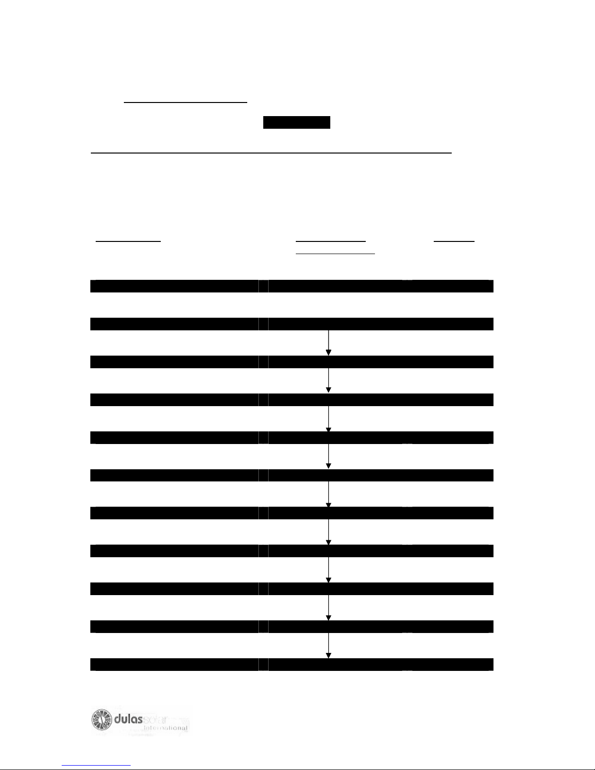
C: FAULT FINDING CHART
CHART NO.1
SYMPTOM - Refrigerator is too WARM and compressor is NOT running.
Check out the following possible faults by first looking at the fault at the top of the
chart. If this is found not to be the fault then move to the next fault in the direction of
the arrows.
Possible fault Fault finding &
Repair Task No.
Page no
Switched OFF Switched ON
User maintenance task D.1. 65
Thermostat D.2. 67
Fuse in compressor controller D.3. 69
Fuse in charge Regulator D.4. 71
Low state of charge of battery D.5. 72
Wiring D.6. 75
Solar Photovoltaic Array D.7. 75
Compressor controller D.8. 76
Charge Regulator D.9. 77
Compressor D.12. 79
73
Page 74
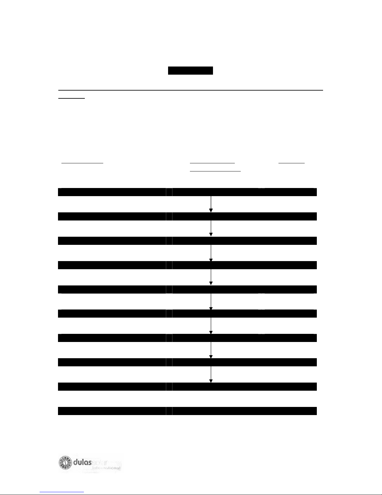
CHART NO. 2
SYMPTOM-Refrigerator is TOO WARM (above 80C) and the compressor is running
at times.
Check out the following possible faults by first looking at the fault at the top of the
chart. If this is found not to be the fault then move to the next fault in the direction of
the arrows.
Possible fault Fault finding &
Repair Task No.
Page no
User Maintenance Task D.1.
Thermostat D.2.
Low State of Charge of Battery D.5.
Wiring D.6.
Solar Photovoltaic Array D.7.
Condenser Fan (when fitted) D.10
Charge Regulator D. 9.
Cooling Circuit D.11
Compressor D.12.
System Sizing D.13.
74
Page 75
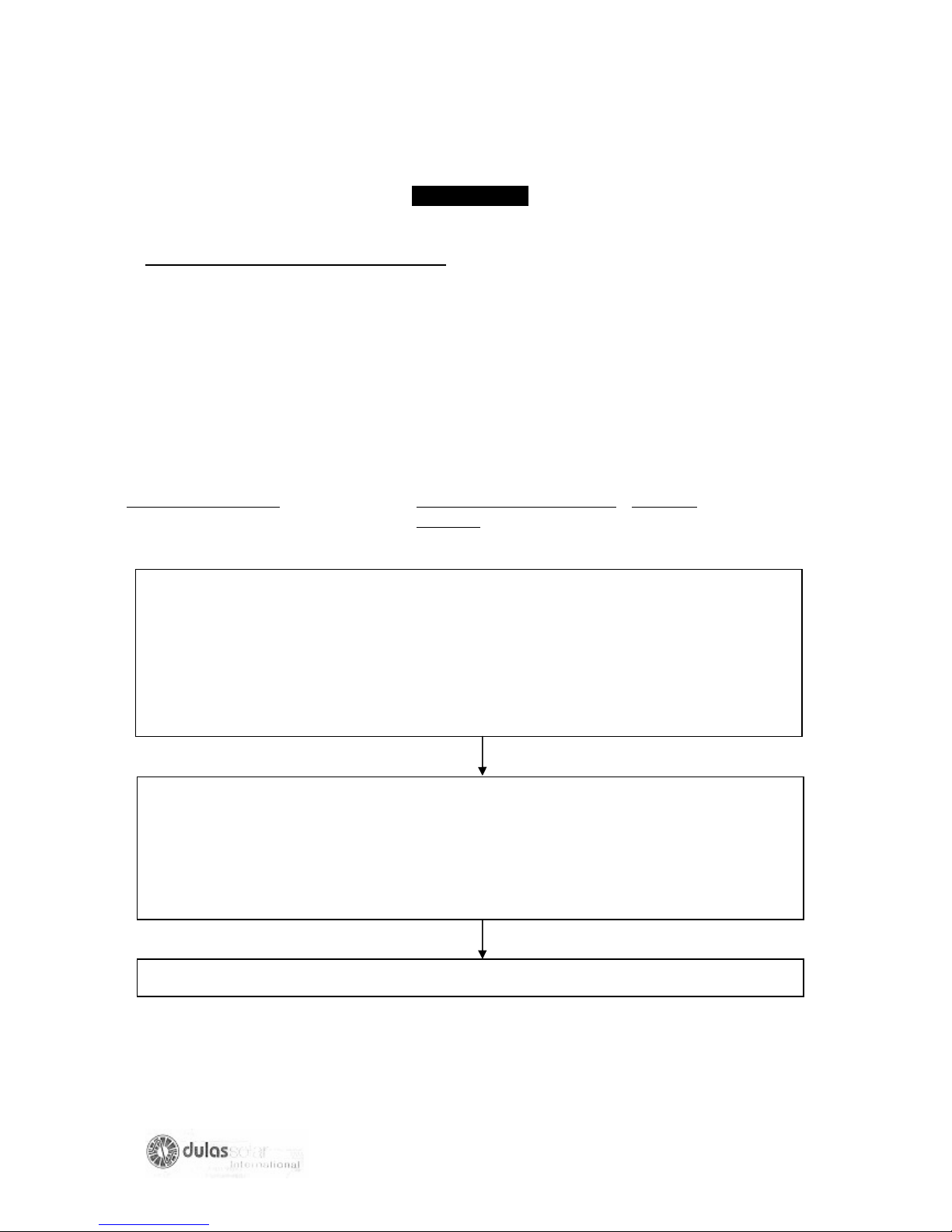
CHART NO. 3 3
SYMPTOM-Refrigerator is TOO COLD
Remember –VACCINE IS DESTROYED IF FROZEN
Check for the following possible faults by first looking at the top of the chart. If this is
found not to be the fault then move to the next fault in the direction of the arrows.
Possible fault Fault finding & Repair
Page no
task No.
Movable Separator replace or repair seperator
Between refrigerator and
Freezer damaged, incorrectly
Positioned or removed.
(Applies only to some types
Of refrigerator cabinets,
E.g. Electrolux RCW 42)
‘Continuous running’,” draw down” Switch the
Or “freezer” switches on. Refrigerator back
(Applies only to some types on to normal mode.
Of refrigerator with these
additional switches)
Thermostat faulty D.2.1 67
75
Page 76

D FAULT FINDING AND REPAIR TASKS DESCRIPTIONS
D.1. USER MAINTENANCE TASKS
The user is responsible for undertaking routine maintenance tasks. If the refrigerator
stops operating correctly, the user is also trained to do simple checks before calling
for the solar refrigerator technician.
IT IS YOUR RESPONSIBILITY TO:
● MAKE SURE THAT THE USER HAS DONE ALL OF HIS MAINTENANCE TASKS
CORRECTLY, AND THE SIMPLE FAULT FINDING CHECKS BY RE-DOING THE
SAME TASKS, AND
● TRAIN THE USER IF ALL TASKS ARE NOT DONE CORRECTLY.
Technician Action required
(a) Check that the DAILY RECORD SHEETS of the user are filed in correctly.
Check:
● the refrigerator temperature record. The refrigerator should ALWAYS been
operating above 00C.
● if there is a record of warning indicator light being lit. The warning indicator lights
are normally labeled as “Do not Freeze Ice Packs” and “Low Battery State of
Charge” or “Refrigerator Disconnected”.
(b) Check that the refrigerator is switched ON, if not, turn it ON.
(c) Check that no obstacles are preventing free air circulation around the refrigerator.
(d) Check that the ice formation on the evaporator is less than 5 mm thick. If it is
more, defrost the refrigerator.
(e) Find out from the User if defrosting is often necessary, if he says ‘Yes’ then check
the lid of door sealing gasket. If the seal is not making good contact, either:
● glue it back on,
● replace the seal, and/or
● adjust the door.
76
Page 77

If it is necessary to replace the seal or adjust the door, check afterwards that the
contact between the lid/door and the refrigerator cabinet is good.
(f) Check that:
● The condenser and compressor are free from dust.
● that the fan (if fitted) turns freely, and
● that the outside of the refrigerator cabinet is clean.
If not clean them thoroughly.
(g) Check that the solar array is clean and that a clean cloth is available to clean the
array.
(h) Check that the solar array is not shaded or even partly shaded from trees or other
obstructions from at least 8.00 a.m. in the morning until 4.00 p.m. in the afternoon. If
it is shaded, cut back the trees or remove the obstacle. If neither is possible it will be
necessary for an installation technician to move the solar array to another place
where it is not shaded.
(I) Check the condition of the batteries:
1) Check the level of electrolyte (acid and water mixture) in each battery cell if the
battery is not sealed type. The metal plate MUST be well covered.
2) Add clean distilled water to the batteries if the metal plates are not covered.
Follow the procedure explained on page 57.
3) Ask the user:
● If he has added distilled water
● in which cells he added water
● When was the last time he added water
● how often he adds water, and to which cells.
77
Page 78

● if the level of water in any cell has ever dropped below the op of the metal plates.
● where he obtains his distilled water, and how often.
● what the distilled water is stored in, and how is the container closed.
This information will help you determine if the batteries are in good condition. Since:
● if a cell in a battery needs water added more often than the other cells, then this
cell is no longer operating correctly and the battery should be replaced.
● if a battery needs water often (more than once in six months) then it is either
poorly ventilated exposed to direct sunlight, or is being deeply discharged in which
case its life will be considerably shortened.
● if a water added to a battery is not clean and distilled; the battery life will be
shortened.
● if the plates of the battery are exposed to the air, then they are damaged and the
battery should be replaced.
(j) If you have DONE ALL of the above user Maintenance Tasks and have not found
anything which would cause the refrigerator not to operate correctly, then PROCEED
TO TEE NEXT STEP ON THE FAULT FINDING CHART.
78
Page 79
D.2. FAULTY THERMOSTAT
2.1 REFRIGERATOR IS TOO COLD (COLDER THAN 00C)
SYMPTOMS OF THE FAULT
1. The refrigerator compartment is too cold.
2. The compressor MAY run all the times
HOW TO CONFIRM THIS FAULT
1.Check the evaporator is adequately defrosted.
2. Check the thermostat-sensing element is firmly attached. (In some refrigerator it is
attached to the evaporator)
3. Adjust the thermostat to its warmest position.
4. If the refrigerator compressor continues to run, the thermostat is faulty. See below
for action required.
5.If the compressor stops running, adjust the thermostat until the temperature in the
refrigerator compartment is above 00Cand below 80C.see page 83 for how to adjust
the thermostat.
Action required
1. Remove ALL vaccine to another refrigerator or cold box with ice packs.
2. If the compressor continues to run when the thermostat is adjusted to any
position, CHANGE THE THERMOSTAT IN ACCORDANCE with the manufacturers
instructions.
3. Reload the refrigerator.
79
Page 80
2.2 REFRIGERATOR TOO WARM (Warmer than 80C)
SYMPTOMS OF THE FAULT
1.The refrigerator compartment is too warm.
2.the compressor MAY not be running or running
Only very occasionally
Hoe to confirm this fault
1. Check the evaporator is adequately defrosted. If it is not this may be the problem.
Defrost the refrigerator.
2. Check that the “Do Not Freeze Ice Packs” or “Refrigerator Disconnected” indicator
lights are not lit. If they are lit the problem is not the thermostat, so proceed to the
next step in the faultfinding chart.
3. Check the thermostat wires are tightly connected to terminals T and C of the
compressor controller. If tightening the connection causes the compressor to run the
fault has been repaired.
4. Check the thermostat wires are tightly connected to the thermostat unit
(Mechanical type only). If tightening the connection causes the compressor to run
the fault has been repaired.
5. Check the wires from the thermostat unit to the compressor controller for signs of
damage. If damage is apparent replace the wire.
6.Adjust the thermostat to its coldest position.
7.If the compressor now runs the thermostat setting was incorrect. Adjust the
thermostat to obtain 20C to 40C in the bottom of the refrigerator compartment as
explained on page 83.
8. If the compressor still does not run connect a wire across the 2 terminals of the
thermostat.
80
Page 81

9. If the compressor runs when you connect the temporary wire, but do not run with
this temporary wire then:
- The thermostat is faulty or
- The wires are incorrectly connected or
- The wires are defective
Repair Action required
1.Tighten, correct or change the wires.
2. If the compressor still does not run CHANGE THE THERMOSTAT in accordance
with the manufacturers instructions.
81
Page 82
D.3. FUSE BLOWN IN COMPRESSOR CONTROLLER
SYMPTOMS OF THE FAULT
1.The refrigerator is TOO warm AND THE COMPRESSOR IS NOT RUNNING
2.REFRIGERATION DISCONNECTED indicator light may be lit.
How to confirm this fault
1.Switch off the regulator.
2.Remove fuse from the compressor controller. Check that the fuse holder is not
corroded and that the fuse fits tightly in the fuse holder.
3. Check the electrical resistance of the fuse.
4. Thoroughly clean the fuse holder.
5.Replace the fuse with a spare fuse that has been checked to be good.
6.Switch the refrigerator on. (Some models also have a circuit breaker protecting the
refrigerator, make sure that it is also switched ON.) If the compressor now runs, the
fault is confirmed and has been replaced.
7.If the compressor does not run check the fuse again. If it has blown against do the
actions listed below.
Repair action require
1.Check that you spare fuse is of the correct type and correct rating.
2.Check that the batteries are of the correct voltage and are connected together
correctly.
3.heck that the connections between the batteries and the compressor controller are
correct and tight. (Positive wires connected to the positive terminal of the
compressor controller and negative to the negative terminal).
4. Switch OFF the refrigerator.
82
Page 83
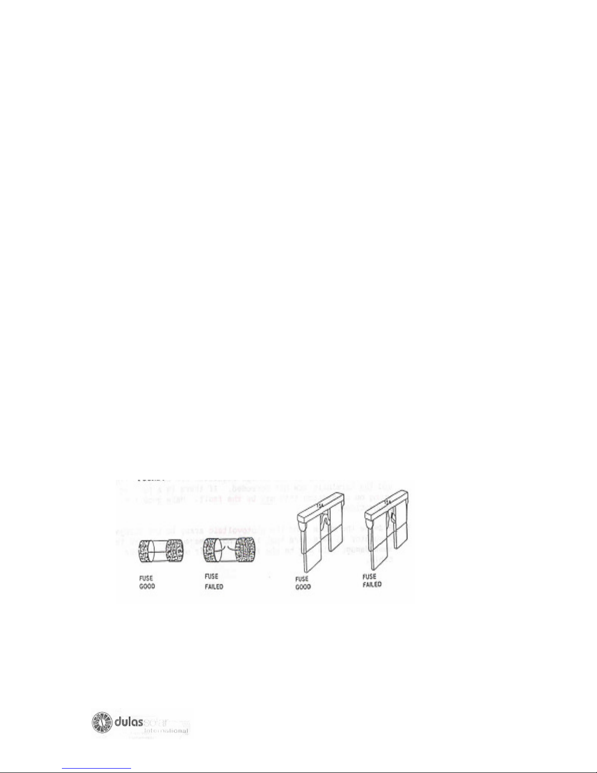
5 Disconnect at the compressor controller the wires from the thermostat and fan (if
fitted). Fit a temporary wire between terminals T and C of the compressor controller.
6.Replace the fuse with a good fuse of the correct type and switch on the
refrigerator.
7. If the refrigerator runs there is fault in the thermostat or fan, which is causing the
fuse to blow, when they are connected. Connect each one separately to determine
which is faulty-the thermostat or the fan.
8. If the fuse blows again, switch OFF the refrigerator, remove the electrical socket
from the compressor. (This disconnects the compressor controller from the
compressor), fit a new fuse, and switch on the refrigerator.
9.If the fuse does not blows with the compressor socket disconnected, the fault is
probably in the compressor. Proceed with the next steps in the faultfinding Chart to
make sure of your diagnosis before replacing the compressor.
10. If the fuse blows each time you replace it and switch on the fridge with and
without the compressor socket disconnected, then change the compressor controller
(see page 85)
11. Fit a new fuse and switch ON the refrigerator again. If with the new compressor
controller the fuse does not blow the fault was the compressor controller. If the fuse
continues to blow, PROCEED TO THE NEXT STEP ON FAULT FINDING CHART
no.1
DO NOT FORGET TO REPLACE THE FUSE LATER WHEN THE FAULT IS
FOUND.
83
Page 84
D4.FUSE BLOWN IN CHARGE REGULATION
SYMPTOMS OF THE FAULT
The refrigerator is TOO WARM and the compressor is not running.
HOW TO CONFIRM THIS FAULT
SOME TYPES OF CHARGE REGULATOR DO NOT HAVE FUSES in the charge
regulator, if this is the case then proceed to the next step on FAULT FINDING
CHART no.1
If the charge regulator is fitted with a fuse then
1.Switch off the refrigerator
2. Remove the fuse from the charge regulator. Check that the fuse holder is not
corroded and that the fuse fits tightly in the fuse holder.
3. Check the electrical resistance of the fuse.
If the fuse has blown take the action detailed below. If the fuse has not blown replace
the fuse and proceed with the next step on the FAULT FINDING CHART NO.1
Repair action require
1Check that you have the correct fuse.
2.Check that the positive and negative connections from the photovoltaic array to the
charge regulator are correct, tight and terminals are not corroded. If there is a poor
or wrong on connection this may be the fault. Make good the connections.
3. Examine the cable from the photovoltaic array to the charge regulator to make
sure that it is not damaged. If there is some damage this may be the fault. Repair or
replace the cable.
84
Page 85

4. Check that the batteries are connected with the correct polarity to the charge
regulator and that any other connections are correct, tight and not corroded.
5.Fit a fuse tested to be good and of the correct size.
6. Switch on the refrigerator. (Some models also have circuit breaker protecting the
refrigerator, make sure that it is also switched on.)
7.Turn off the refrigerator, take out the fuse and check it.
If the fuse is:
- Blown then PROCEED TO THE NEXT STEP ON THE FAULT FINDING CHART
to find out why the fuse is blowing.
DO NOT FORGET TO REPLACE THE FUSE LATER
- Not blown, also PROCEED TO THE NEXT STEP ON THE FAULT FINDING
CHART. This is because the original fuse must have blown for a reason, and you
have to find the reason.
85
Page 86
D5: LOW STATE OF CHARGE OF BATTERIES
THE BATTERIES MAY BE FAULTY OR MAY ONLY HAVE A LOW STATE OF
CHARGE as a result of a long period of cloddy weather.
SYMPTOMS OF THE FAULT
1 The refrigerator is too warm.
2 The voltmeter (not fitted to all models) shows battery voltage to be less than 11.5
V.
3.THE REFRIGERATOR DISCONNECTED indicator light is lit of has lit recently.
How to confirm fault
1.Cover the solar array so that NO sunlight falls on it.
2.Check that the refrigerator is switched ON.
3.measure the voltage of the batteries at the + and – terminals of the compressor
controller.
- The voltage should be greater than 11.5 volts for 12-volt systems (22.6
volts
for 24 volt systems) if the compressor is NOT running.
- The voltage should be greater than 10.5 volts for 12 volts systems (21.3
volts for 24 volt systems) if the compressor IS running.
4. If the voltage at the compressor controller terminals is not greater than the values
shown above, the batteries have a low state of charge.
Repair action required
1. Switch off the regulator.
2. If you have a fully charged replacement battery available (2 batteries for 24 volt
system) remove the battery from the refrigerator and connect the fully charged
battery.
86
Page 87

3. With the solar array still covered, switch ON the refrigerator. THE
REFRIGERATOR COMPRESSOR SHOULD NOW RUN.
4. If the COMPRESSOR DOES NOT RUN PROCEED TO THE NEXT STEP ON
THE FAULT FINDING CHART.
5. If the COMPRESSOR DOES NOT RUN:
(a) Check the level of distilled water in each cell of each battery, and top up
the
water if necessary (see page 57)
(b) Recharge each battery (unless battery manufacturer or supplier states this
is not to be done for your batteries)
6. Recharge the batteries by switching OFF the refrigerator and:
(a) Allowing five days for the batteries to be recharged by the solar array, OR
(b) By removing the batteries from the refrigerator and charging with a battery
charger.
(c) When fully charged by either method, disconnect each battery and leave
each battery for 2 hours.
(d) Connect the battery (2 batteries for 24 volts system) to the refrigerator,
switch in the refrigerator and measure the voltage between the + and –
terminals of the compressor controller.
(e) If the voltage of the battery with the compressor running is LESS THAN
12.5 volts (or 25 volts for 24 volt system), the battery is not holding the
charge and should be replaced (see page 87)
(f) Repeat step (d) for each of the batteries you have charged.
(g) Reconnect the correct number of batteries required for the solar
refrigerator.
(h) If NO batteries need replacing, PROCEED TO THE NEXT step on the
FAULT FINDING CHART, which corresponds with the symptom you, have
diagnosed. This will enable you to find out if the low state of charge of your
batteries is the result of other fault in your system.
87
Page 88
D6. WIRING
SYMPTOMS OF THE FAULT
1. The refrigerator is too warm and the compressor is not running.
2.The refrigerator operates normally sometimes but at other times the refrigerator
Is too warm and the compressor is not running.
How to confirm this fault
1. Check the voltage at:
(a) The terminals of the charge regulator WHICH ARE CONNECTED TO THE
SOLAR ARRAY CABLE. In sunlight this voltage should be 13.5 to 19 volts. (27
to 38 volts for 24-volt system)
(b) The + and – terminals of the compressor controller, the voltage should be 11.5
to 13 volts if the batteries are adequately charged. (23 to 26 volts for 24-volt
system)
2. If the voltage at the charge regulator and the compressor controller do not
corresponds with the above values, then there may be wiring fault. See below for
what action you should take.
Repair action required
1. Switch OFF the refrigerator.
2.Label wires before disconnecting them so that you know where to reconnect them.
3. Inspect all the electrical cables and connections. Repair or replace any, which are
visibly defective.
4. Disconnect the solar array wires from the charge regulator.
5.Clean all terminals of the charge regulator and solar array junction box.
88
Page 89
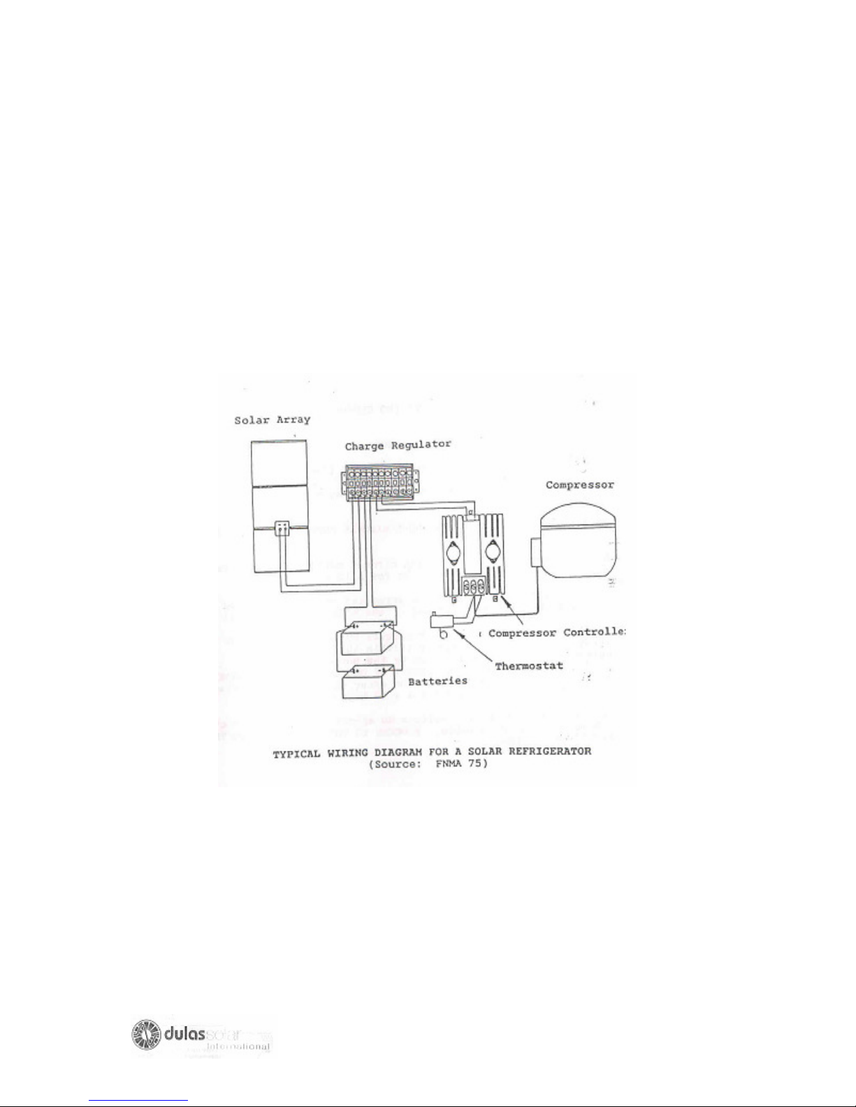
6. Check the voltage at the charge regulator and compressor controller again as
detailed above under” How to confirm this fault.”
If the voltages are now correct the faults has been repaired.
If the voltage is still not correct PROCEED WITH THE NEXT CHECK ON THE
FAULT FINDING CHART.
89
Page 90
D.7 PHOTOVOLTAIC ARRAY
SYMPTOMS OF THE FAULT
1. The refrigerator is too warm and the compressor is not running or is running only
very occasionally.
2. The Batteries become discharge periodically.
3. The indicator lights for normal operations my not be lit or the “Refrigerator
Disconnected” and “Do not Freeze Ice Packs” lights are often lit.
How to confirm this fault
ON A DAY WHEN THE SKY IS CLEAR (NO CLOUDS) AND AT ABOUT MIDDAY;
1.Clean the solar array (see page 54)
2. Check that the solar array is not shaded (see page 54)
3.Disconnect from the solar array, the array cable that leads to the charge regulator.
4. Measure and write down the short circuit current of the solar array (see page 52)
5.Measure and write down the open circuit voltage of the solar array .It should be 1720 volts for a 12-volt system.
6. Disconnect one module from the array and measure and write down the short
circuit current of the module (see page 52)
For 12-volt systems the short circuit current in the solar array should be
approximately (within 15%)equal to the current in a module multiplied by the number
of modules. (For example if the short circuit of one module is 2.5 Amps and there are
four modules in the array then the solar array short circuit should be 2.5 * 4 = 10
Amps).
7. If the array current and voltage do appear correct reconnect the module and array
cable. PROCEED TO THE NEXT CHECK IN THE FAULT FINDING CHART.
90
Page 91
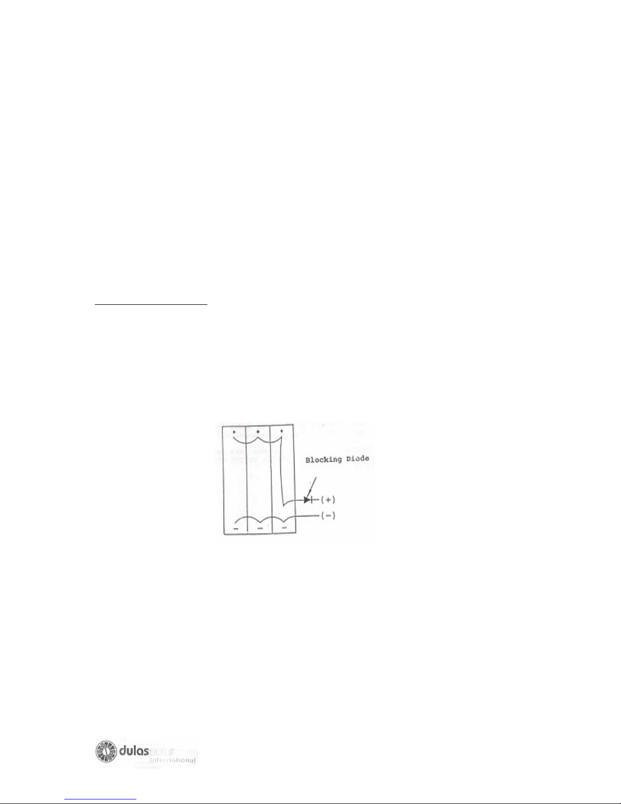
8.If the solar array short circuit current or open current voltage does not appear
correct then there may be a fault with a module or the way the modules are
connected together.
9.Measure the open circuit voltage and short circuit current in each module with each
module disconnected from the other modules.
10.If the voltage and current measured on one module is not similar, to other
modules (more than 15% different) the module is probably faulty and should be
replaced.
11. If the voltage and current of all the modules are similar then there was probably a
poor connection on one module or faulty wire.
Repair action required
1.If a module is faulty (replace it as described on page 82)
2.If a wiring fault or connection fault between modules is suspected check the
electrical continuity of each wire and clean all the wire terminals.
3.Reconnect all the modules to the array and check all connections are correct.
Typical wiring for 1 12-volt system is shown below.
4. Check the output of the solar array again to confirm that the correct array
current is approximately equal to the current of one module times the number of
modules and hence is correctly connected.
91
Page 92
D.8 COMPRESSOR CONTROLLER
SYMPTOMS OF THE FAULT
The refrigerator is too warm and the compressor does not run
How to Confirm this fault
Measure the voltage at the input terminals of the compressor controller. If the voltage
is more than 11.5 volts (12 volt system) or more than 22.5 volts (24 volts system) the
compressor should run. If the compressor does not run, proceed as follows.
Repair action required
1. Remove the thermostat and compressor fan wires (if fitted). From terminals T, C,
and F of the compressor controller. Fit a temporary wire between terminals T and C.
The compressor should then run.
2. If the compressor does not run, CHECK THE FUSE, in the compressor controller
again as explained on page no 69.
3. If the compressor still does not run, change the compressor controller with another
of the same model (or compressor controller specified by the system supplier) see
page 85.
4. If the compressor still does not run, the compressor controller is NOT
FAULTY.PROCEED TO THE NEXT STEP ON THE FAULT FINDING CHART No.1
92
Page 93
D.9 CHARGE REFULATOR FAULTY
SYMPTOMS OF THE FAULT
1. The refrigerator is too warm and the compressor is not running only occasionally.
2.The batteries become discharged periodically.
How to confirm this fault
1. If all previous steps in the faultfinding procedures have not indicated a fault then
change the charge regulator (see page 84) and see if the refrigerator operates
normally for at least one month.
Repair Action required
1. If after replacing the charge regulator the solar refrigerator works correctly for one
month the fault was probably the Charge Regulator.
93
Page 94
D.10 CONDENSER FAN (If fitted)
SYMPTOMS OF THE FAULT
The refrigerator is too warm and the compressor is a not run very frequently.
How to confirm this fault
When the compressor is running look to see if the condenser fan is rotating.
If it is rotating this is not the problem. Proceed to the next check in the faultfinding
chart.
If it is not rotating a fault if indicated, see below for the action you should take.
Repair action required
1. Switch off the regulator.
2. Disconnect the fan wires from the compressor controller. Check the continuity of
each wire. If a break in a wire is detected replace the wire.
3. Clean the connections and reconnect the fan wires to the compressor controller.
4.Check to see if the fan can freely rotate. If it is jammed remove the item that is
stopping it from rotating.
5.Switch ON the refrigerator.
6. If the fan now rotates when the compressor is running the fault has been repaired.
7.If the fan still does not rotate replace the fan as described on page 86.
94
Page 95
D.11. COOLING CIRCUIT FAULT
SYMPTOMS OF THE FAULT
The refrigerator is too warm and the compressor is a not run continuously or very
frequently.
How to confirm this fault
1. If the compressor runs and the evaporator plate do not get cold all over then:
(a) The cooling circuit may be undercharged with refrigerant, or
(b) The capillary tube blocked, or
(c) There may be moisture in the system
2. If the refrigerator is correctly charged with refrigerant, there must be liquid in the
pipe coming out of the condenser. To check this, do the following:
(a) Adjust the thermostat to its coldest setting and run the compressor for at least
five minutes.
(b) With the compressor running, hold a lighted match under the condenser outlet
pipe until the match is finished.
(c) As soon as the match has gone out put your finger on the pipe here the match
heater it.
(d) The pipe should be warm only. The liquid in the pipe will absorb if there is
liquid inside the pipe the heat form the match. If the pipe is too hot for you to keep
your fingers on it, then there is no liquid in the pipe. These mean that the refrigerator
is not adequately charged with refrigerant.
Repair action required
IF YOU ARE SURE THAT the symptoms indicate that there is insufficient refrigerant
in the refrigerator or there may be problem with moisture or a blockage, then REFER
TO THE TECHNICIANS HANDBOOK FOR COMPRESSION REFRIGERATORS,
PART B, FAULTS AND FAULTS FINDING. Page 7 gives a faultfinding chart and
procedure to find and replace the fault.
95
Page 96
D.12 COMPRESSOR
SYMPTOMS OF THE FAULT
The refrigerator is too warm.
How to confirm this fault
1. Measure the Voltage at the input terminals of the compressor controller. If the
voltage is more than 11.5 volts (12 volt system) or more than 22.5 volts (24 volts
system), the compressor should run.
2. If the compressor runs continuously and the refrigerator temperature does not
decrease to less than 80C after 4 hours, a cooling circuit problem is evident go to
page 77.
3. If the compressor does not run, proceed as follows.
4. Switch OFF the refrigerator and disconnect the electrical socket from the
compressor.
5.Measure the electrical RESISTANCE between the following connections on the
compressor plug with your OHMMETER :(see diagram on Pins on next page)
- Pins No. 1 and 3.
- Pins No. 4 and 3.
- Pins No. 2 and 3.
The electrical RESISTANCE should be VARY LOW between these connections.
6.Measur the electrical RESISTANCE between Pin No. 3 and the metal body of the
compressor. Make sure that you have good electrical contact between your
OHMMETER lead and the compressor metal body. The electrical RESISTANCE
should be VERY HIGH.
7. If the electrical RESISTANCE between the compressor pins (see Para .5.above)
is not VERY LOW and the electrical RESISTANCE between pin No.3 and the
compressor body is NOT VERY HIGH, then the compressor is faulty.
96
Page 97
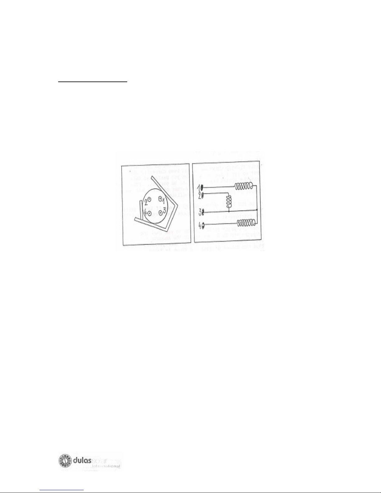
Repair action required
1. ONLY CHANGE COMPRESSOR WHEN YOU ARE SURE THAT ALL PREVIOUS
STEPS IN THE FINDING CHART HAVE BEEN CAREFULLY CHECKED.
2. Replace the compressor in accordance with the manufacturers instructions,
Refer also to the procedure described in the WHO handbook for COMPRESSION
refrigerator repairs. (Refer to the inside of the front cover of this handbook for
details.)
97
Page 98
D.13 SYSTEM SIZING
SYMPTOMS OF THE FAULT
1. Refrigerator operates correctly during certain seasons, but the battery becomes
discharged at times in the year when it is not very sunny or the ambient temperature
is high.
2. The indicator light “Do NOT Freeze Icepacks” and possibly “Refrigerator
Disconnected” are lit early in the morning especially at the times in the year when it
is not very sunny or the ambient temperature is high.
How to confirm this fault
1. If you are sure that each of the checks you have made in FAULT FINDING
CHART NO.2 has been correctly performed and that no fault was found, when you
performed these checks, then the system sizing may not be correct. (The system
sizing is incorrect if numbers of solar modules and/or the number of batteries are
insufficient.
2.Check the DAILY RECORD SHEETS to see if large quantities of vaccine and /or
medical supplies are frequently loaded into the refrigerator.
3. Check the DAILY RECORD SHEETS to see that the quantities of icepacks frozen
do not exceed the amounts recommended in the USER HANDBOOK for photovoltaic
refrigerator, Table 1, and that the amount of icepacks shown in Table 1 is not more
than the quantity specified for this type of refrigerator system.
4.Check with the person who is responsible for the refrigerator to make sure that the
food and drinks and other non-medical supplies are not being kept in the refrigerator
and that items other than icepacks are not being frozen in the freezer compartment.
98
Page 99

5. If the above checks indicate that the refrigerator is being correctly operated and
that no parts of the system are defective, then closely observe the operation of the
refrigerator during several days and note when the indicator lights shows “Do Not
Freeze Icepacks” and possibly “Refrigerator Disconnected”.
6. If the problem continues a part of the system may be undersized.
Repair action required
1.Write down your findings on the DAILY RECORD SHEETS kept by the user:
2. Prepare a note with a full explanation of checks performed and your conclusions
that there may be a problem with sizing.
3. Send or preferably hand-deliver your note to:
(a) The chief of the solar refrigerator installation team.
(b) The person responsible for solar refrigerator in the organization responsible for
the EPI program in your country.
(c) Ask your head of department to send a copy of your note to the Cold Chain
Unit. Expanded programme on Immunization at the World Health Organisation, 1211
Geneva-27, Switzerland.
4. Advise the user that he or she should refrigerate only vaccine and other essential
items and should try to minimize the number of unfrozen ice packs placed in the
freezer at one time.
REMEMBER: VACCINE AND ESSENTIAL MEDICAL ITEMS ONLY SHOULD BE
IN THE REFRIGERATOR
99
Page 100

E. REPAIR TECHNIQUES
E.1 INTRODUCTION
Some of the repair tasks that you may have to carry out on the cooling system of a
solar powered refrigerator are similar to those for a normal compression refrigerator.
These have been fully described in the Technicians Handbook for compression
refrigerators Parts A, B and C, produced by WHO Expanded Programme on
Immunization. You should have a copy of each of these three booklets in order to
carry out the repair tasks listed below.
(a) Replacing a thermostat (see part C)
(b) Replacing a compressor ((see part C)
(c) Mending a refrigerant leak (see part A & part C)
(d) Recharging the refrigerant loop when the system is undercharged (see part A
& part B)
(e) Recharging the refrigerant loop when the system is overcharged (see part B)
(f) Replacing the evaporator (see part C)
(g) Replacing a capillary tube (see part C)
(h) Replacing a fitter/drier (see part C)
(i) Replacing the lid /door sealing gasket
(j) Adjusting the lid/door sealing
(k) Adjusting dropped or twisted doors.
Other repair tasks that you may have to carry out on a solar powered refrigerator are
described in the following pages.
You should also always refer to the maintenance and repair handbook of the solar
refrigerator manufacturer, if these are available as their instructions should be more
specific.
100
 Loading...