

Page 1
DUKERS GAS FRYERS
INSTALLATION & OPERATION
MANUAL
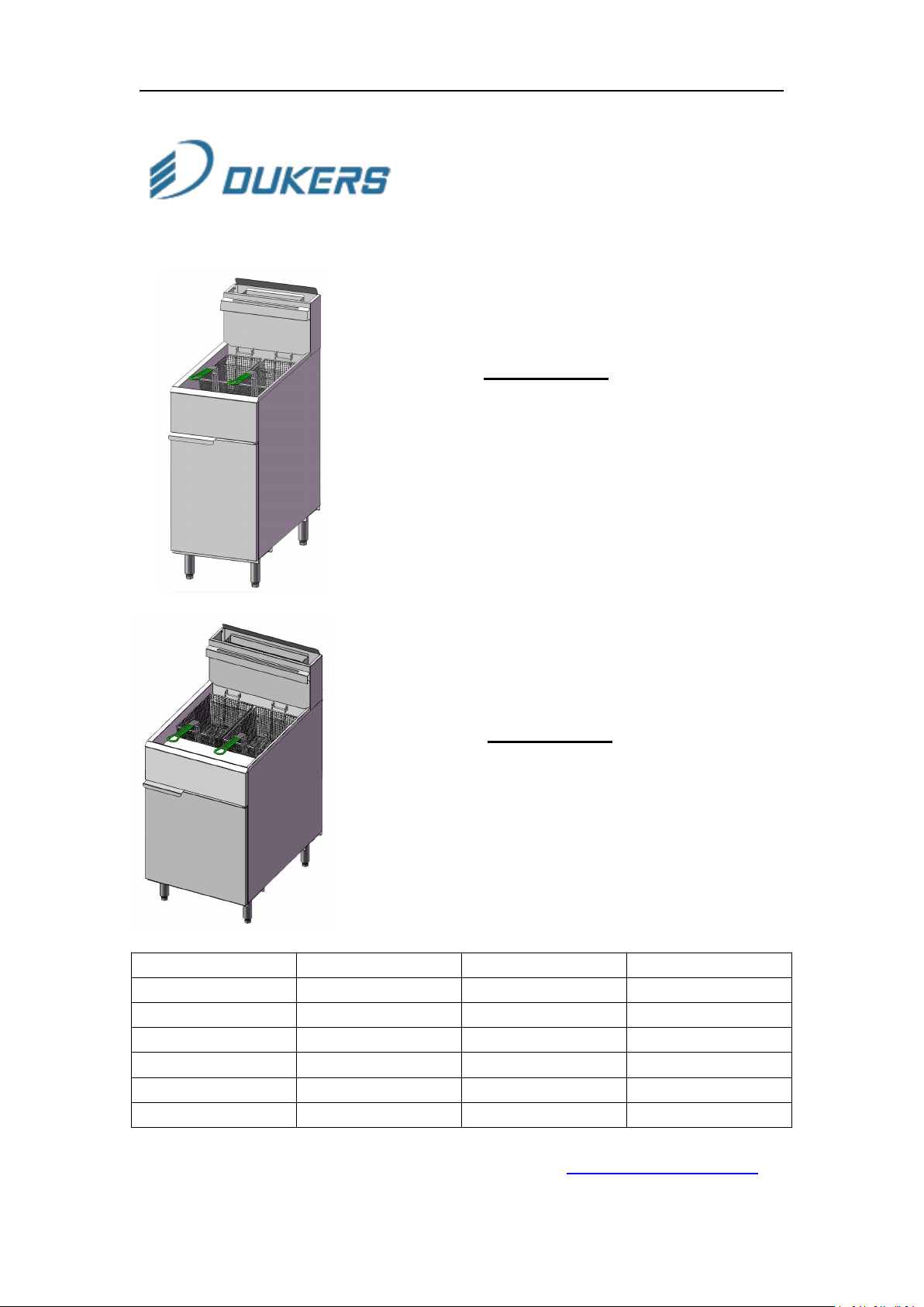
Gas Fryers
Models
DCF3-LPG
DCF3-NG
DCF4-LPG
DCF4-NG
Models
DCF5-LPG
DCF5-NG
Model
Gas type
Tubes
Gas pressure
DCF3-LPG
Propane
3
10”WC
DCF3-NG
Nature gas
3
4”WC
DCF4-LPG
Propane
4
10”WC
DCF4-NG
Nature gas
4
4”WC
DCF5-LPG
Propane
5
10”WC
DCF5-NG
Nature gas
5
4”WC
1-800-931-8628 | [email protected] | WWW.DUKERSUSA.COM
1
Page 2
DUKERS GAS FRYERS
△
!
WARNING
In the event a gas odor is detected, shut down equipment at the
combination gas valve and contact the local gas company or gas
supplier for service
△
!
WARNING
FOR YOUR SAFETY
Keep area around appliances free and clear of combustibles.
Purchaser of equipment must post in a prominent location, detailed
instructions to be followed in the event the operator smells gas.
Obtain the instructions from the local gas supplier.
△
!
WARNING: Improper installation, adjustment, alteration,
service or maintenance can cause property damage, injury or death.
Read the installation, operating and maintenance instructions
thoroughly before installing or servicing this equipment.
FOR YOUR SAFETY
Do not store or use gasoline or other flammable vapors and liquids
in the vicinity of this or any other appliance.
2
Page 3
DUKERS GAS FRYERS
△
!
WARNING
FOR YOUR SAFETY
LP-gas cylinders are not to be stored in any compartments on the
appliance that are not intended for cylinder storage and that such
unauthorized storage could lead to an explosion, fire, or personal
injury.
-SAFETY PRECAUTIONS-
Before installing and operating this equipment, be sure everyone involved in it
operation is fully trained and aware of precautions. Accidents and problem can be
caused by failure to follow fundamental rules and precautions.
The following symbol, found throughout this manual, alert you to potentially
dangerous conditions to the operator, service personnel, or to the equipment.
!
△
DANGER
This symbol warns of immediate hazards that will result in severe injury or death
!
△
WARNING
This symbol refers to a potential hazard or unsafe practice that could result in
injury or death
!
△
WARNING
Hot oil and parts can cause burns. Use care when operating, cleaning and
servicing the fryer
!
△
CAUTION
This symbol refers to a potential hazard or unsafe practice that could result in
injury, product damage, or property damage
!
△
NOTICE
This symbol refers to information that needs special attention or must be fully
understood, even though not dangerous
3
Page 4

DUKERS GAS FRYERS
!
△
WARNING
BURN HAZARD
Contact with hot oil will cause severe burns. Always use caution. Oil at 200℉ is
more dangerous than boiling water.
!
△
NOTICE
Gas floor model fryers are intended for commercial use only. Not for household
use Warranty will be void if service work is performed by other than a qualified
technician, or if other than genuine replacement parts are installed.
Be sure this Operator ‘S Manual and important papers are given to the proper
authority to retain for future reference
Congratulations! You have purchased one of the finest pieces of commercial cooking
equipment on the market
You will find that your new equipment has been designed and manufactured to meet
the toughest standards in the industry. Each equipment is carefully engineered and
designs are verified through laboratory tests and field installations. With proper care
and field maintenance, you will experience years of reliable, trouble-free operation.
For best results, read this manual carefully
RETAIN THIS MANUAL FOR FUTURE REFERENCE
MODELS
This manual is for Gas floor model Fryers with 40 lbs., 50 lbs. and 70 lbs. capacity fry
pots. The capacity is described on the serial plate that is located inside the front door
on the left side.
Table of Contents
Installation------------------------------------------------------------------------------5
Operation-------------------------------------------------------------------------------14
Cooking hints--------------------------------------------------------------------------16
Cleaning---------------------------------------------------------------------------------16
Service (for authorized service technician only) -----------------------------18
Parts--------------------------------------------------------------------------------------23
Read these instructions carefully before attempting installation. Installation and
initial startup should be performed by a qualified installer. Unless the installation
instructions for this product are followed by a qualified service technician (a person
experienced in and knowledgeable with the installation of commercial gas and/or
electric cooking equipment) then the terms and conditions on the Manufacturers
Limited Warranty will be rendered void and no warranty of any kind shall apply.
4
Page 5

DUKERS GAS FRYERS
Gas Supply and Burner Information
Supply pressure should be minimum of 4" W.C. for natural gas or 10" W.C for propane.
The fryer comes with 3/4" NPT male connector on a 1/2 pipe allowing you to connect
with either 3/4" or 1/2" NPT female connector.
The minimum environmental temperature for safe use of the appliance : -20℉
5
Page 6
DUKERS GAS FRYERS
Unpacking & Installation
INSTALLATION
NOTICE
Installation must conform with local codes, or in the absence of local codes
with the National Fuel Gas Code, ANSI Z223.1, Natural Gas Installation Code,
CAN/CGA-B149.1, or the Propane Installation Code, CAN/CGA-B149.2, as
applicable.
NOTICE
These installation procedures must be followed by qualified personnel or
warranty will be void.
Local codes regarding installation vary greatly from one area to another. The
National Fire Protection Association, Inc. states in its NFPA 96 latest edition
that local codes are the authority having jurisdiction when it comes to
installation requirements for equipment
UNPACK
IMMEDIATELY INSPECT FOR SHIPPING DAMAGE
All containers should be examined for damage before and during unloading. The
freight carrier has assumed responsibility for safe transit and delivery. If damaged
equipment is received, either apparent or concealed, a claim must be made with the
delivering carrier.
Apparent damage or loss must be noted on the freight bill at the time of delivery.
The freight bill must then be signed by the carrier representative (Driver). If the bill is
not signed, the carrier may refuse the claim. The carrier can supply the necessary
forms.
A request for inspection must be made to the carrier within 15 days if there is
concealed damage or loss that is not apparent until after the equipment is uncrated.
The carrier should arrange an inspection be certain to hold all contents plus all
packing material.
1. Uncrate carefully. Report any hidden damage to the freight carrier IMMEDIATELY
2. Do not remove any tags or labels until unit is installed and working properly.
6
Page 7
DUKERS GAS FRYERS
△
!
WARNING
FOR YOUR SAFETY
If the appliance is designed for use with a hose that will lie
on the ground,the hose must be protected from damage.
Do not use hoses that have expired its lifespan.
The hose needs to be far away from the fire source to avoid
thermal deformation.
Make sure to use a pipe clamp to fasten the connection of the
hose interface.
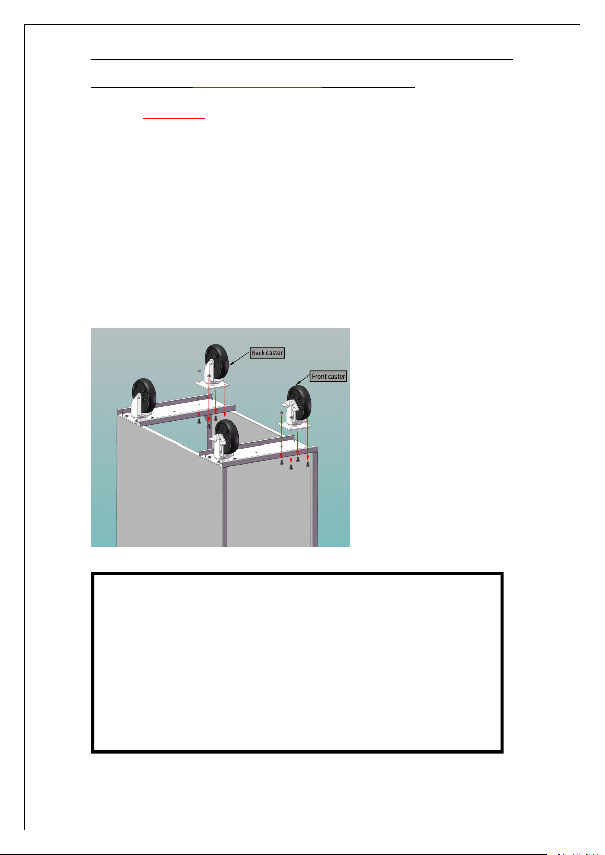
INSTALL THE LEGS(OR OPTIONAL CASTERS)AND RESTRAINTS
A set of legs is packed with the fryer. Casters are optional, purchased separately(part
number:18.001.0003). Mounting fasteners are pre-mounted on the base plates.
1. Raise fryer sufficiently to allow legs to be screwed into the base plate. For safety,
"shore up" and support the fryer with an adequate blocking arrangement strong
enough to support the load.
2. Screw the four legs or casters to the plate on the bottom of the fryer. When casters
have been ordered, the casters having a locking-brake should be attached under
the front of the fryer
3. Lower the fryer gently. Never drop or allow the fryer to fall.
4. Use a level to make sure that the fryer is level. Each caster, or the tubular-end leg,
can be screwed in or out to lower or raise each corner of the fryer.
5. Attach restraints as required by local codes.
6. The front and back wheels are marked as "FRONT CASTER" and "BACK CASTER"
respectively, so install them in their respective locations as shown below:
7
Page 8
DUKERS GAS FRYERS
NOTICE
Unit must be level to assure maximum performance. Improper leveling may void
warranty.
WARNING
If disconnection of the restraint is necessary to move the appliance for cleaning,
etc., reconnect it when the appliance is moved to its original installed position.
WARNING
All fryers must be restrained to prevent tipping in order to avoid the splashing of
hot liquid.
When using, keep the oil level of the oil pan not exceeding the "MAX" limit
line.
Prevent the hot oil from splashing caused by water dripping into the tank
NOTICE
When this appliance is installed with casters, it must be installed with the
casters supplied, a connector complying with either ANSI Z21.69 CSA 6.16 or a
quick-disconnect device complying with ANSI Z21.41 CSA 6.9. It must be also
installed with restraining means to guard against transmission of strain to the
connector; this restraint device is installed on the caster in the front of the
product (as part of the caster). When the product is installed in place, please
pull the restraint device of the caster to the "ON" position. If you want to move
the equipment, make sure that the gas source is completely disconnected then
pull the restraint device of the caster to the "OFF" position.
WARNING
When the fryer is filled with hot oil, do not move the fryer. Forcibly moving the
fryer may cause serious injury to the human body. When you need to move the
item, please cut off the gas source first, wait for the oil in the cylinder to cool
down, then empty the cylinder, and finally move it.
8
Page 9
DUKERS GAS FRYERS
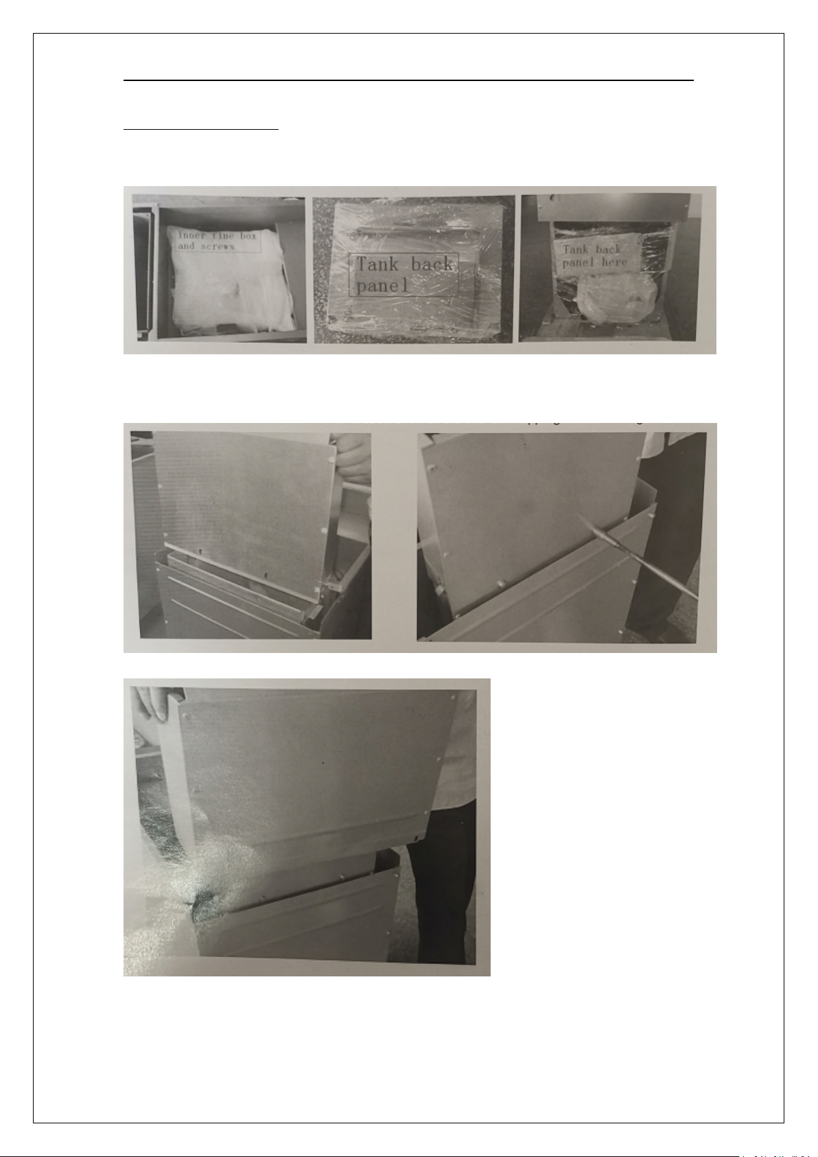
FLUE INSTALLATION
1. Unpack the flue box and flue wrap
2. Slide the flue box over the flue and secure it with the two self-tapping screws
using a 5/16” socket
3. Slide the flue wrap over the flue
9
Page 10
DUKERS GAS FRYERS
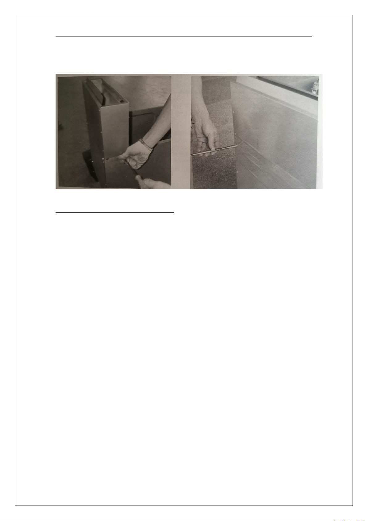
4. Secure it with four self-tapping screws two on the back and one on each side
using a 5/16 socket
Check Clearances and Ventilation
Select a firm, level location for your fryer. Leave clearance, whenever possible, so
that access from the rear is possible to permit cleaning. If the unit is to be set on
non-combustible flooring, such as a concrete slab inches minimum toe room must be
provided to prevent restriction of the air opening in the bottom of the unit.
10
Page 11

DUKERS GAS FRYERS
!
△
WARNING
There must be adequate clearance between fryer(s) and construction. Clearance
must also be provided in front for servicing and for operation
Minimum Clearances:
From Non-Combustible Material
Sides 0 inches
Rear 0 inches
From Combustible Construction
Sides 8 inches
Rear 12 inches
ALL GAS FLOOR MODEL FRYERS SHALL BE INSTALLED WITH AT LEAST A 16 INCH SPACE
BETWEEN THE FRYER AND SURFACE FLAMES FROM ADJACENT EQUIPMENT. A FLAME
GUARD /S ACCEPTABLE /F ALLOWED UNDER LOCAL CODE.
A clearance of not less than 16 in (400mm) shall be provided between this deep fat
fryer and an open flame of an adjacent appliance unless a noncombustible divider
extending not less than 7 in (175mm) above the fryer and the open flame of the
adjacent appliance is provided.
No additional side and rear clearance is required for service as the fryer is
serviceable from the front.
!
△
WARNING
Improper ventilation can result in personal injury or death. Ventilation that fails
to properly remove flue products can cause headaches, drowsiness, nausea, or could
result in death Unit must be installed under a ventilation hood
All units must not be installed in such a manner that the flow of combustion and
ventilation air is obstructed. Provisions for adequate air supply must also be provided.
Do NOT obstruct the bottom front of the unit, as combustion air enters through this
area. Be sure to inspect and clean the ventilation system according to the ventilation
equipment manufacturer's instructions.
Due to the variety of problems that can be caused by outside weather conditions,
venting by canopies or wall fans is preferred over any type of direct venting. It is
recommended that a canopy extend 6" past the appliance and the bottom edge be
located 6' 6"from the floor. Filters should be installed at an angle of 45 or more from
the horizontal. This position prevents dripping of grease and facilitates collecting the
run-off grease in a drip pan, unusually installed with a filter. A strong exhaust fan
tends to create a vacuum in the room and may interfere with burner performance or
may extinguish pilot flames. Fresh air openings any appliance, check the appliance
with the exhaust fan in the "OFF" position. Do these only long enough to check
11
Page 12
DUKERS GAS FRYERS
equipment performance, then turn hood back on and let it run to remove any
exhaust that may have accumulated during the test.
The exhaust fan should be installed at least 2 feet above the vent opening at the top
of the fryer.
Make sure all ventilation meet local code requirement.
This unit is not intended to be connected directly to an outside flue.
GAS CONNECTION
A 3/4"male NPT line for the gas connection is located near the lower right rear
corner of the fryer. The serial plate(located inside the front door of the
fryer)indicates the type of gas the unit is equipped to burn(natural gas or propane).
The fryer should be connected only to the type of gas for which it is equipped.
A circuit diagram is located inside the front door of the fryer.
This equipment is adjusted at the factory; however, pilot height should be checked at
installation and adjusted, if necessary.
For orifice sizes and pressure regulator settings, see the chart on page 4. If the fryer
is being installed at over 2,000 feet altitude and that information was not specified
when ordered, contact the appropriate authorized Service Representative or the
Service Department. Failure to install with all with proper orifice sizing will result in
poor performance and may void the warranty.
If applicable, the vent line from the gas appliance pressure regulator shall be installed
to the outdoors in accordance with local codes or, in the absence of local codes, with
the National Fuel Gas Code, ANST Z223.1, Natural Gas Installation Code,
CAN/CGA-B149.1, or the propane Installation Code, CAN/CGA B149.2, as applicable.
The appliance and its individual shutoff valve must be disconnected from the gas
supply piping system during any pressure testing of that system at test pressures in
excess of 1/2psi (3.5kPa).
The appliance must be isolated from the gas supply piping system by closing tis
individual manual shutoff valve during any pressure testing of the gas supply piping
system at test pressures equal to or less than 1/2psi (3.5kPa).
An adequate gas supply is imperative. Undersized or low pressure lines will restrict
the volume of gas necessary for satisfactory performances. A combination gas valve
and pressure regulator, which is provided with each unit, is set to maintain a 4" W.C.
12
Page 13

DUKERS GAS FRYERS
manifold pressure for natural gas or 10.0"W C. manifold pressure for propane gas.
However, to maintain these conditions the pressure on the supply line, when all units
are operating simultaneously, should not drop below 7" W.C. for natural gas or
11"W.C. for propane gas.
Fluctuations of more than 25% on natural gas or 10% on propane gas will create
problems and affect burner I operating characteristics. A 1/8"tap to measure the
manifold pressure is located on the combination gas valve, which is on the burner
manifold located directly below the burners inside the cabinet.
Purge the supply line to clean out dust, dirt, or other foreign matter before
connecting the line to the unit.
It is recommended that an individual manual shutoff valve be installed in the gas
supply line to the unit.
Use pipe joint compound that is suitable for use with both natural and Lp gas on all
threaded connections.
13
Page 14
DUKERS GAS FRYERS
ALL PIPE JOINTS AND CONNECTIONS MUST BE TESTED THOROUGHLY
FOR GAS LEAKS.
USE ONLY SOAPY WATER FOR TESTING ON ALL GASES. NEVER USE AN OPEN FLAME
TO CHECK FOR GAS LEAKS. ALL CONNECTIONS MUST BE CHECKED FOR LEAKS AFTER
THE UNIT HAS BEEN PUT INTO OPERATION. TEST PRESSURE SHOULD NOT EXCEED
14"W C
THIS APPLIANCE AND ITS IND/VIDUAL COMBINAT/ON GAS VALVE
MUST BE DISCONNECTED FROM THE GAS SUPPLY PIPING SYSTEM DURING ANY
PRESSURE TESTING OF THAT SYSTEM AT TEST PRESSURES IN EXCESS OF 14WC(1/2
PSIG or 3. 45 kPa)
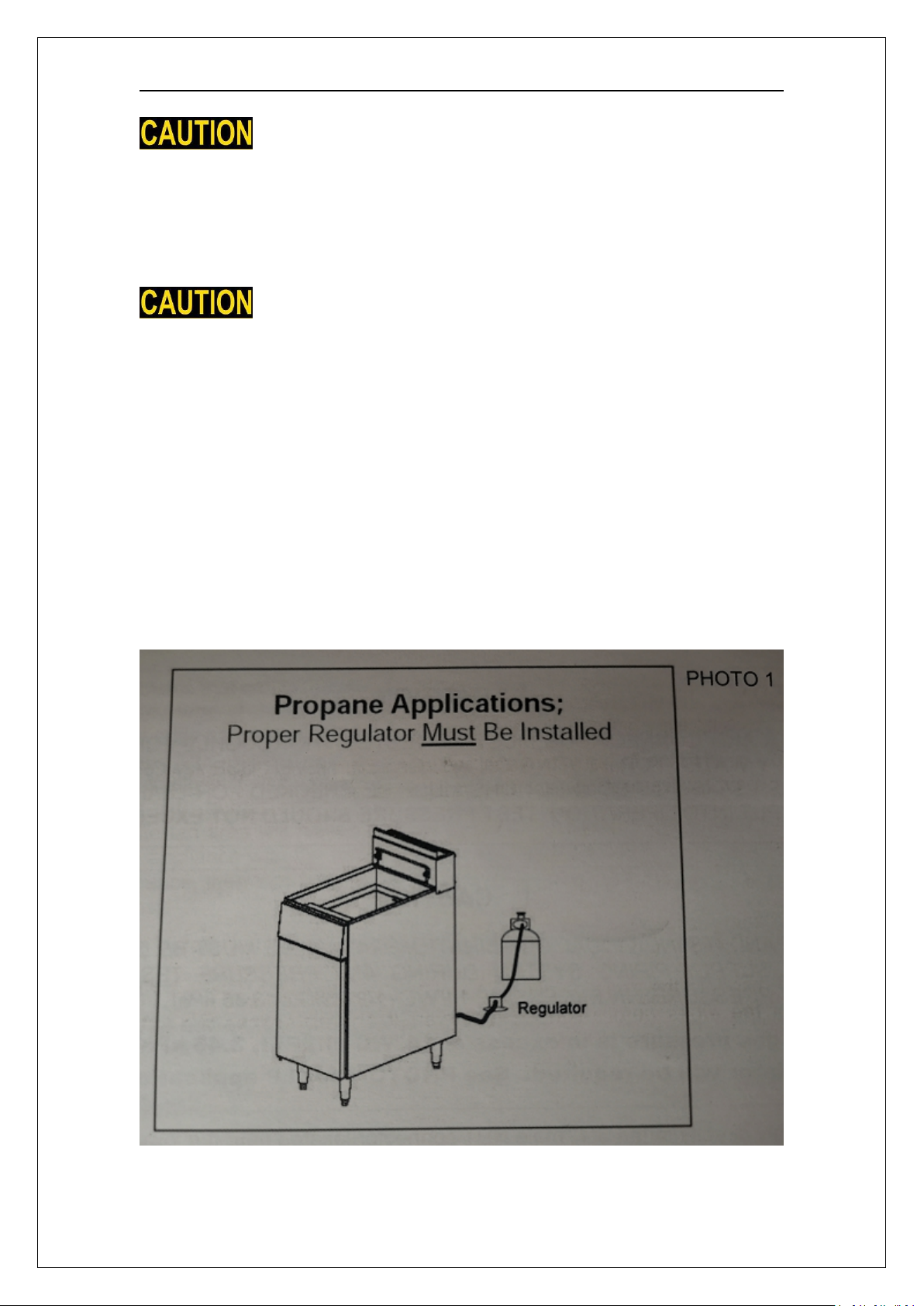
If the incoming gas pressure is in excess of 14 wc (1/2PSl, 3. 45 kPa), a proper
step-down regulator will be required. See photo 1 for LP application
Connect the gas supply directly to the 3/4"male NPT connector located near the
lower left rear corner of the fryer. When tightening the supply pipe, be sure to hold
the mating connector extending from the unit securel with a wrench. This will
prevent any damage or distortion to the internal piping and controls of the unit.
After connecting the gas supply, check again that the fryer is level. Use a long spirit
level four ways, across the front and rear of the frypot, and along each edge.
14
Page 15
DUKERS GAS FRYERS
△
!
CAUTION
IF YOU SMELL GAS DURING THE LIGHTING PROCEDURE IMMEDIATELY SHUT OFF THE
GAS SUPPLY UNTIL THE LEAK HAS BEEN CORRECTED
OPERATION
LIGHTING
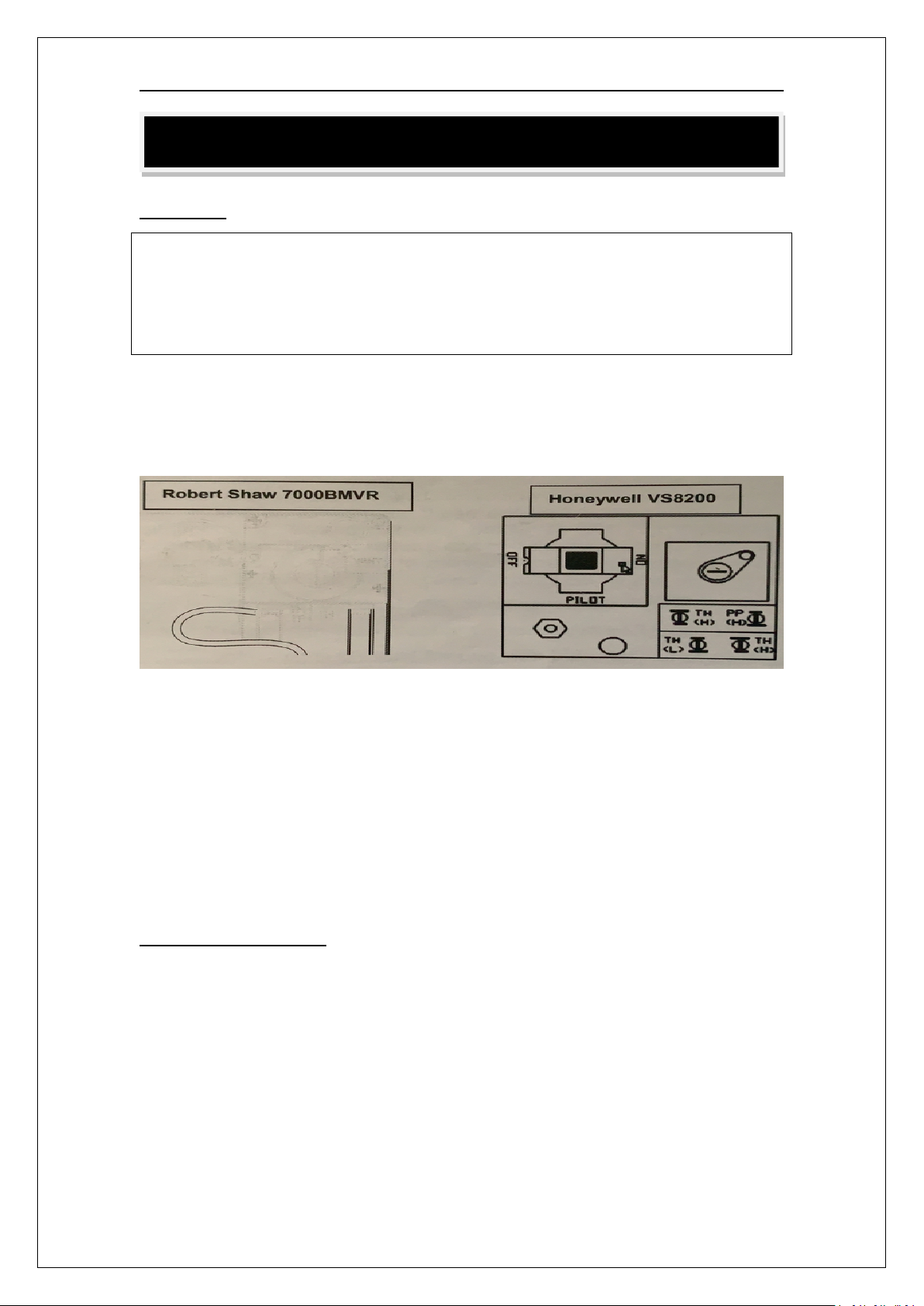
Open the burner compartment door and do the following
1. Turn thermostat to“OFF”
2. Press down the knob of the combination gas valve, turn it counterclockwise to
the"PILOT"
3. While pressing the knob down, use a lit match to ignite the pilot. Continue to press
the knob down for about 30 seconds. If the pilot does not stay lit when the knob is
released, repeat the lighting procedure and keep the knob down longer.
Adjustment of pilot flame may be necessary
4. When the pilot stays lit, turn the knob counterclockwise to the"ON position. Do
not press down on theknob in this step
5. Do NOT turn the thermostat"ON"until the frypot is filled with oil or solid
shortening
6. Once the frypot is filled with shortening, set the thermostat to the desired
temperature.
FILLING THE FRY POT
1.Close drain valve completely before filling the fry pot
2.When the fryer is new, fill the fry pot with water and clean thoroughly (see "Weekly
Cleaning" on page 15)in order to remove protective coatings and any foreign matter
3. The recommended solid shortening capacity for the fry pot (35, 55 or 60lbs) is
described on the serial plate(which is located inside the front door
4.Remove the basket support frame when filling the fry pot with solid shortening
5.When solid shortening is used. be careful not to bend, break, or twist the thin
capillary wires of the sensing elements located in the fry pot
6. Pack solid shortening into the zone below the tubes, all spaces between the tubes,
15
Page 16
DUKERS GAS FRYERS
CAUTION
NEVER ATTEMPT TO MELT A SOLID BLOCK OF SHORTENING ON TOP OF THE HEAT
TUBES
NEVER START THE BURNERS WHEN THE FRYPOT /S EMPTY.
1. DO NOT overfill fry basket
2. Carefully turn lower baskets into oil
3. Only turn items frying once while cooking
4. When cooking French fries of onion rings, etc., shake the basket(carefully, to
avoid splattering oil)to keep items in basket separated while cooking
5. Battered foods should be dropped carefully, one at time, into fry basket or oil
6. If using basket, dip it first into the hot oil to prevent batter from building up on
the baskets surfaces
7. When cooking is complete, remove basket or food items from oil. Hang basket
on rear hanger
Hot oil and parts can burns. Use care when operating, cleaning and servicing the
fryer
1. Filter oil at least once a day. Refer to the instructions provided with your
filtering equipment
2. A cold fryer will not drain properly; Always filter oil between 254℉ and 350℉
(123℃ and 177℃)
3. The shortening in the cold zone area will remain hard if the heat is only on for
a few minutes. if necessary, use a clean-out rod to carefully stir the hard
shortening to an area above the cold zone where it will melt
4. Use the tank brush to help clear sides and tubes of debris
and at least an inch above the top of the tubes before lighting the fryer. If any air
spaces are left around the heat tube surfaces when the heat is turned on the tube
surfaces will become red hot, burn the solid shortening, weaken the fry pot, and
could result in a fire.
7. To prevent burning or scorching the solid shortening, keep the thermostat set at
the lowest temperature until all the solid shortening between and above the tubes
has been melted. Additional solid shortening can then be added until the desired
frying depth has been reached replace the basket support frame over the fry pot
heat tubes
!
△
WARNING:
!
△
WARNING:
SHUTDOWN PROCEDURE
Standby: Turn knob on the combination gas valve to the "PILOT" position. At this
setting, only the pilot burner will remain ignited Complete Shutdown: Turn knob on
the combination gas valve clockwise, press down on the knob and continue to turn to
the "OFF" position
16
Page 17
DUKERS GAS FRYERS
△
!
WARNING
In the event of a main burner ignition failure, a five minute purge period must be
observed prior to reestablishing the ignition source
RELIGHTING
1. Shut off all gas
2. Wait five minutes
3. Follow the "Lighting" procedure described on page 13
AUTOMATIC PILOT VALVE
The Automatic Pilot Valve provides an automatic safety shutoff for the fryer when
the pilot flame is extinguished. When the pilot flame is burning, the valve is held
open electromagnetically by the electrical current from a thermopile in the pilot
flame. When the pilot flame goes out, generation of current ceases and the valve
closes automatically
HIGH LIMIT CONTROL
Gas floor model fryers are equipped with a secondary heat control that prevents the
oil temperature from rising above 450 ℉.(Because of the accuracy tolerance of the
sensor, the oil temperature may reach as high as 475℉)
In the event the fryer shuts down due to this condition, the oil must be cooled to
below 400 F before the pilot burner can be re-ignited. When the oil has cooled, use
the "Lighting "procedure on page 13 to place the fryer back in operation. If the
problem persists, contact your local Service Representative or the Service
Department
COOKING HINTS
USER TIPS
Smoking oil means that the temperature is too high, or that the oil has broken
down Gum in fry pot denotes a need for thorough cleaning (see Weekly Cleaning
on page 16)
Use different oil for oily foods (mackerel, nutmeg, etc. than for foods with
water-soluble flavors (potatoes onions, etc.).
Taste cool oil for quality. Replace it regularly, poor oil cannot produce good food
CLEANING
The equipment is constructed with the best quality materials and is designed to
provide durable service when properly maintained. To expect the best performance,
your equipment must be maintained in good condition and cleaned daily. Naturally,
the frequency and extent of cleaning depends on the amount and degree of usage
Following daily and more extensive periodic maintenance procedures will increase
17
Page 18
DUKERS GAS FRYERS
△
!
WARNING: BURN HAZARD
If necessary to move the fryer for cleaning, etc, drain oil first to avoid death or
serious injury
△
!
WARNING
If disconnection of the restraint is necessary to move the appliance for cleaning, etc,
reconnect it when the appliance is moved to it originally installed position
△
!
CAUTION
SOME AREAS OF THE FRYPOT MAY BE HOT!
the life of your equipment Climatic conditions (e.g. salt air) may result in the need for
more thorough and more frequent cleaning in order to keep equipment performing
at optimal level
DAILY CLEANING
Turn thermostat knob to "OFF" position
Place hot-oil in a safe container under the drain and drain the fry pot completely
Remove the basket support frame (if applicable) and flush out any sediment
remaining in the fry pot with a little hot oil.
Wipe off the basket support frame and the inside of the fry pot with a clean
cloth
Close drain valve and strain the oil back into the fry pot through several
thicknesses of cheesecloth, or pour it back using a filter machine
Replace the basket support frame (if applicable
Add oil or shortening to MIN oil level mark on rear of fry pot
To resume cooking, turn the combination gas valve knob to "ON position
WEEKLY CLEANING
1. Follow steps 1 through 4 of the Daily Cleaning procedure (see previous section)
2. Close drain valve and fill fry pot with a solution of warm water and boil-out
compound
3. Relight the fryer and bring the solution to a gentle boil for at least five minutes
4. Turn off main burners and let the solution stand until the gum deposits are
softened and the carbon spots and burned grease spots can be rubbed off
5. Scrub the fry pot walls and heat tubes, then drain out fry pot and rinse it with
clean water
6. Refill the fry pot with clean water and boil again
7. Turn off gas and drain and rinse well until clean
18
Page 19
DUKERS GAS FRYERS
NOTICE
Warranty will be void and the manufacturer is relieved of all liability if:
(A)Service work is performed by other than a qualified technician( see page 30 for
detail)
OR
(B)Other than approved replacement parts are installed
8. Wipe dry with a clean cloth
9. Refill as specified in the "Filling the Fry pot section (see page 13) "
MONTHLY CLEANING
1. Perform the Weekly Cleaning procedure (see previous section)
2. Clean around burner and orifices if lint has accumulated
3. Visually check that burner carry-over ports are unobstructed
CLEANING STAINLESS STEEL SURFACES
To remove normal dirt, grease and product residue from stainless steel use ordinary
soap and water (with or without detergent) applied with a sponge or cloth.
Dry thoroughly with a clean cloth. Never use vinegar or any corrosive cleaner
To remove grease and food splatter or condensed vapors that have baked on the
equipment apply cleanser to a damp cloth or sponge and rub cleanser on the metal
in the direction of the polishing lines on the metal. Rubbing cleanser, as gently as
possible, in the direction of the polished lines will not mar the finish of the stainless
steel. NEVER RUB WITH A CIRCULAR MOTION. Soil and burnt deposits that do not
respond to respond to the above procedure can usually be removed by rubbing the
surface with SCOTCH-BRITETM scouring pads or STAINLESS scouring pads.
DO NOT USE ORDINARY STEEL WOOL, as any particles left on the surface
Will rust and further spoil the appearance of the finish. NEVER USE A WIRE BRUSH,
STEEL SCOURING PADS(EXCEPT STAINLESS), SCRAPER, FILE OR OTHER STEEL TOOLS.
Surfaces that are marred collect dirt more rapidly and become more difficult to clean
Marring also increases the possibility of corrosive attack. Refinishing may then be
required
Darkened areas, called "heat tint, sometimes appear on stainless steel surfaces
where the area has been subjected to excessive heat. These darkened areas are
caused by y thickening of the protective surface of the stainless steel and are not
harmful. Heat tint can normally be removed by the above cleaning techniques, but
tint which does not respond to that procedure calls for a vigorous scouring in the
direction of the polish lines, using SCOTCH-BRITETM scouring pads or a STAINLESS
scouring pad in combination with a powered cleanser. Heat tint action may be
lessened by not applying or by reducing, heat to equipment during slack periods
SERVICE (FOR AUTHORIZED SERVICE TECHNICIAN ONLY)
19
Page 20
DUKERS GAS FRYERS
△
!
WARNING
Adjustments and service work may be performed only by a qualified technician who
is experienced in and knowledgeable with, the operation of commercial gas cooking
equipment.
However, to assure your confidence, contact your Service Representative for reliable
service, dependable advice or other assistance, and for genuine factory parts
All units are adjusted at the factory. In case of problems in operation at initial
installation, check type of gas and manifold pressure and compare with information
listed on the serial plate A mill voltage circuit diagram is located inside the front door
of the fryer, and also on page 19
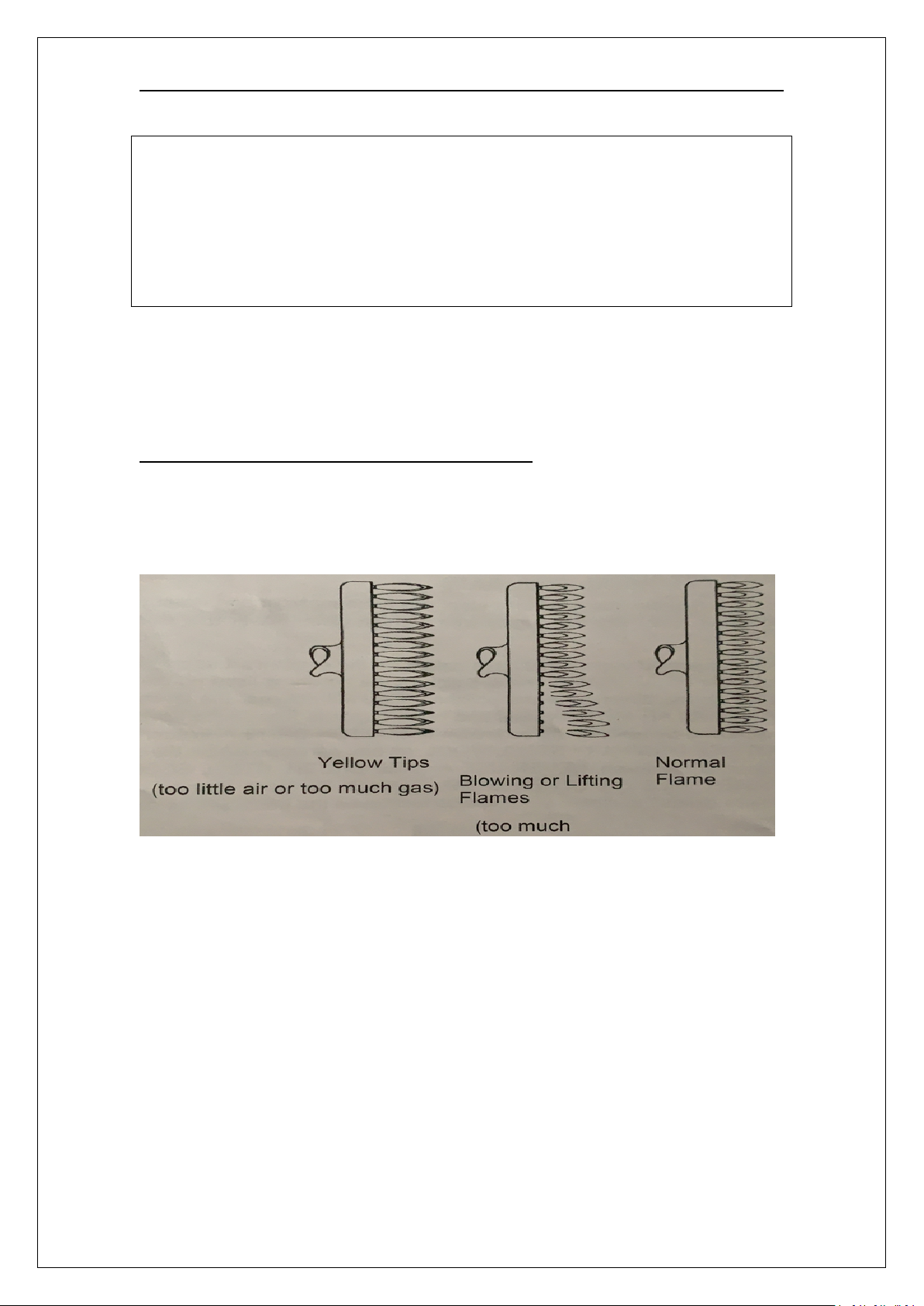
CHECKING AND ADJUSTING MAIN BURNERS
The main burners should burn with a steady flame, and the inner cone of the flame
from each port should be about 3/4"long. The flame from each main burner should
enter each heat tube without touching the front of the fry pot or the sides, top, or
bottom of each tube
20
Page 21
DUKERS GAS FRYERS
CHECKING AND ADJUSTING PRESSURE REGULATOR
The combination gas valve (includes pressure regulator) is factory set at 4"W.C. for
natural gas and 10"WC for propane gas. To check the manifold pressure, do the
following
1. Turn thermostat "OFF and combination gas valve knob to the "PILOT" setting
2.Remove pressure tap plug from burner manifold located directly below the burners
in the cabinet
3. Install a fitting appropriate to connect a manometer
4. Turn combination gas valve to "ON position and thermostat to “ON: "The burners
will ignite. Be certain that sufficient oil is covering the tubes
5. With burners on, read manometer
6.if the manometer does not read 4"W C for natural gas, or 10"W. C for propane gas,
adjust regulator
7. Remove regulator adjustment screw cap (see diagram on page 15)
8.With small screwdriver rotate adjustment screw "CLOCKWISE" to increase or
"COUNTERCLOCKWISE to decrease pressure. Be sure to adjust with burners "ON
9. Turn thermostat "OFF" and set combination gas valve knob to "PILOT" position
10. Remove manometer and replace pressure tap plug
11. Replace adjustment screw cap
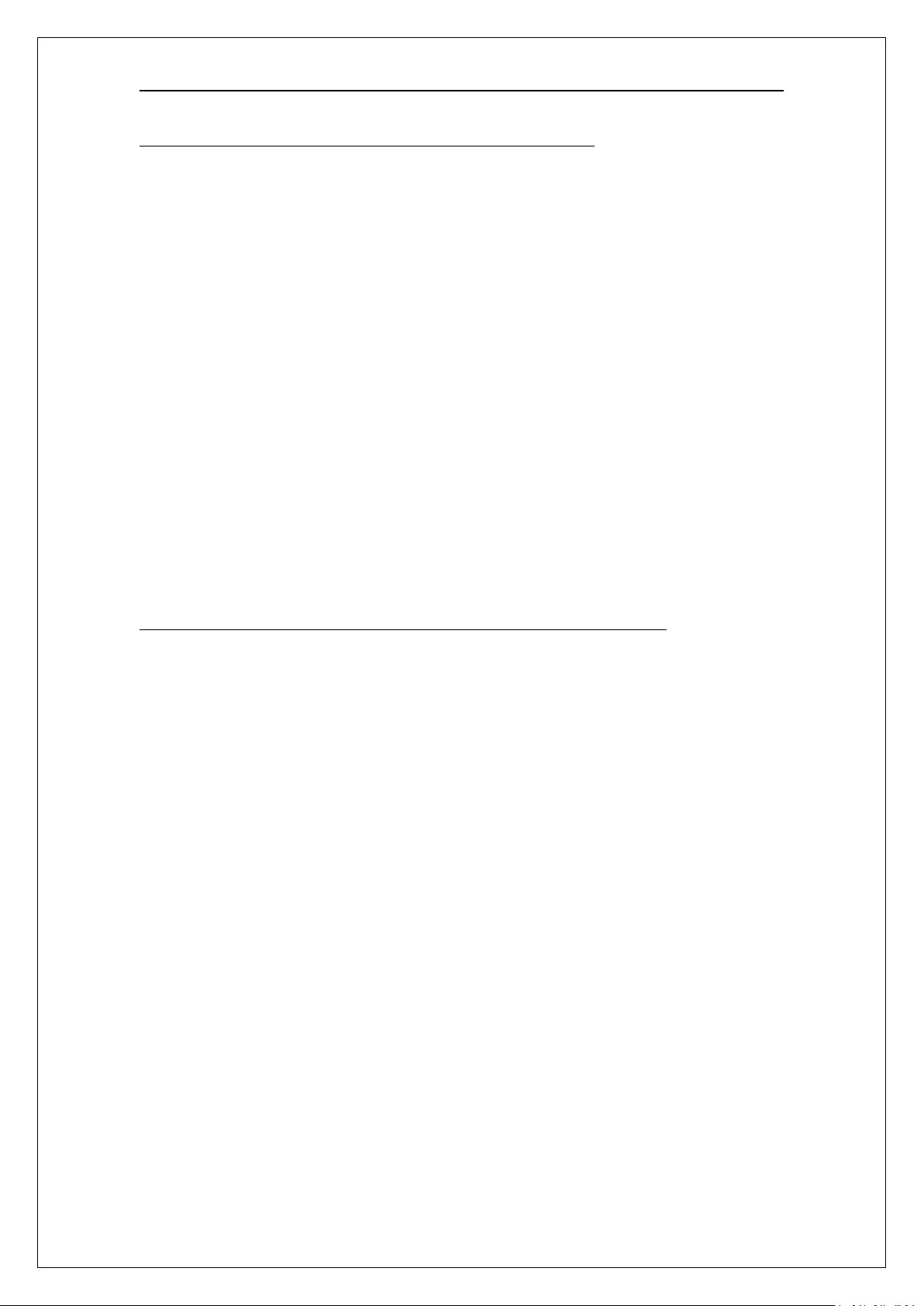
CHECKING AND ADJUSTING CALIBRATION OF THERMOSTAT
All thermostat controls are carefully calibrated at the factory (i.e, the dial is properly
set to control appliance temperatures accurately). Only a qualified appliance service
technician should perform this adjustment
1. To check appliance temperatures, use a thermocouple-type temperature test
instrument or reliable thermometer. Place the thermocouple of test instrument or
thermometer in the center of the fry pot
2. Turn the control dial to the temperature setting requiring the greatest accuracy.
Allow enough time for temperature to stabilize, or until several temperature readings
are identical
3. Recalibrate if setting and actual temperature differ by more than 10F
4. Remove dial from dial shaft "B. Be careful that dial shaft does not rotate in either
direction (which would change the dial setting)
5. Hold dial shaft "B" steady and with a screwdriver SHAFT urn calibration screw "A"
clockwise to decrease the B temperature, or counterclockwise to increase the
temperature
6. Replace dial. Let the appliance operate until the temperature has stabilized before
a final check is made to determine whether or not the calibration has been corrected
7. Once correct. seal the calibration screw with glycol.
21
Page 22
DUKERS GAS FRYERS
CHECKING AND ADJUSTING AUTO SAFETY PILOT
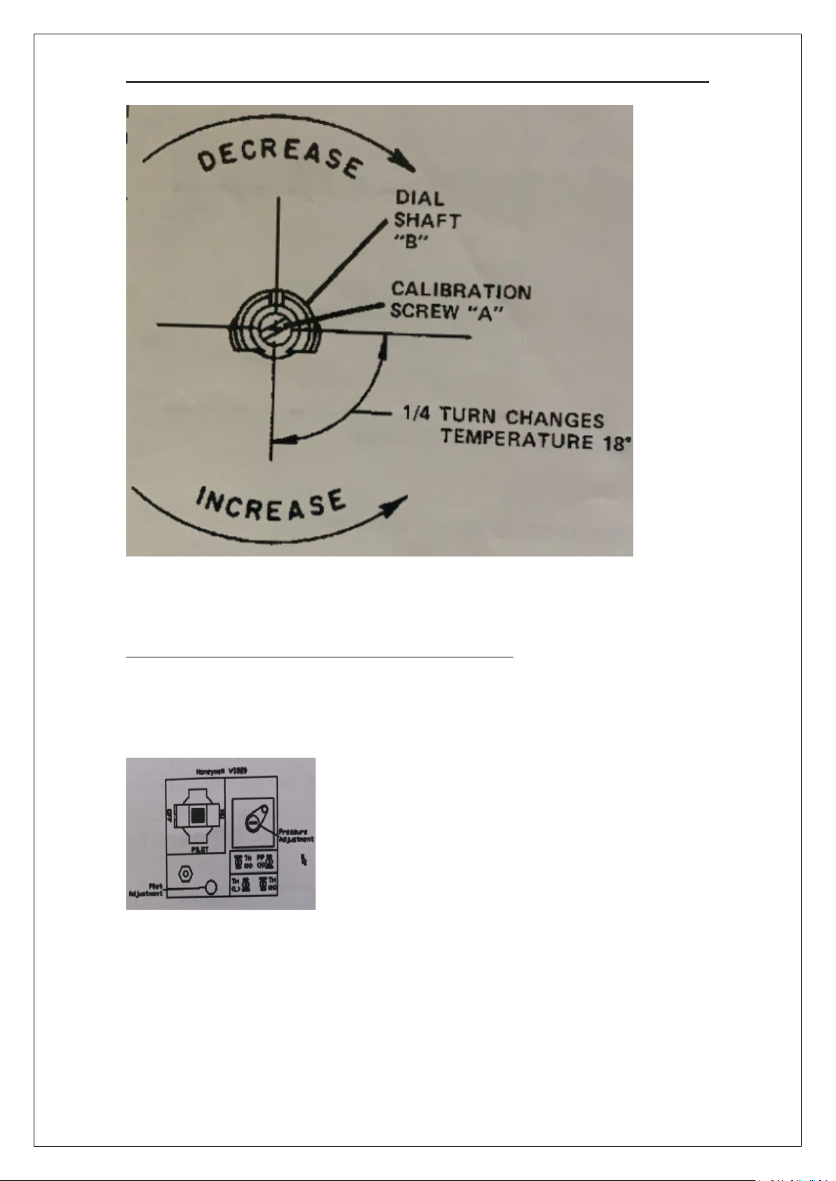
The plot flame should surround the thermopile for 1/2". It must be large and sharp
enough to cause the thermopile to glow a dull red, or sufficient to hold the safety
valve open
1. Remove pilot adjustment cap
2. Adjust pilot key to provide properly sized flame shown in diagram B Diagram A
shows an improperly adjusted pilot
22
Page 23
DUKERS GAS FRYERS
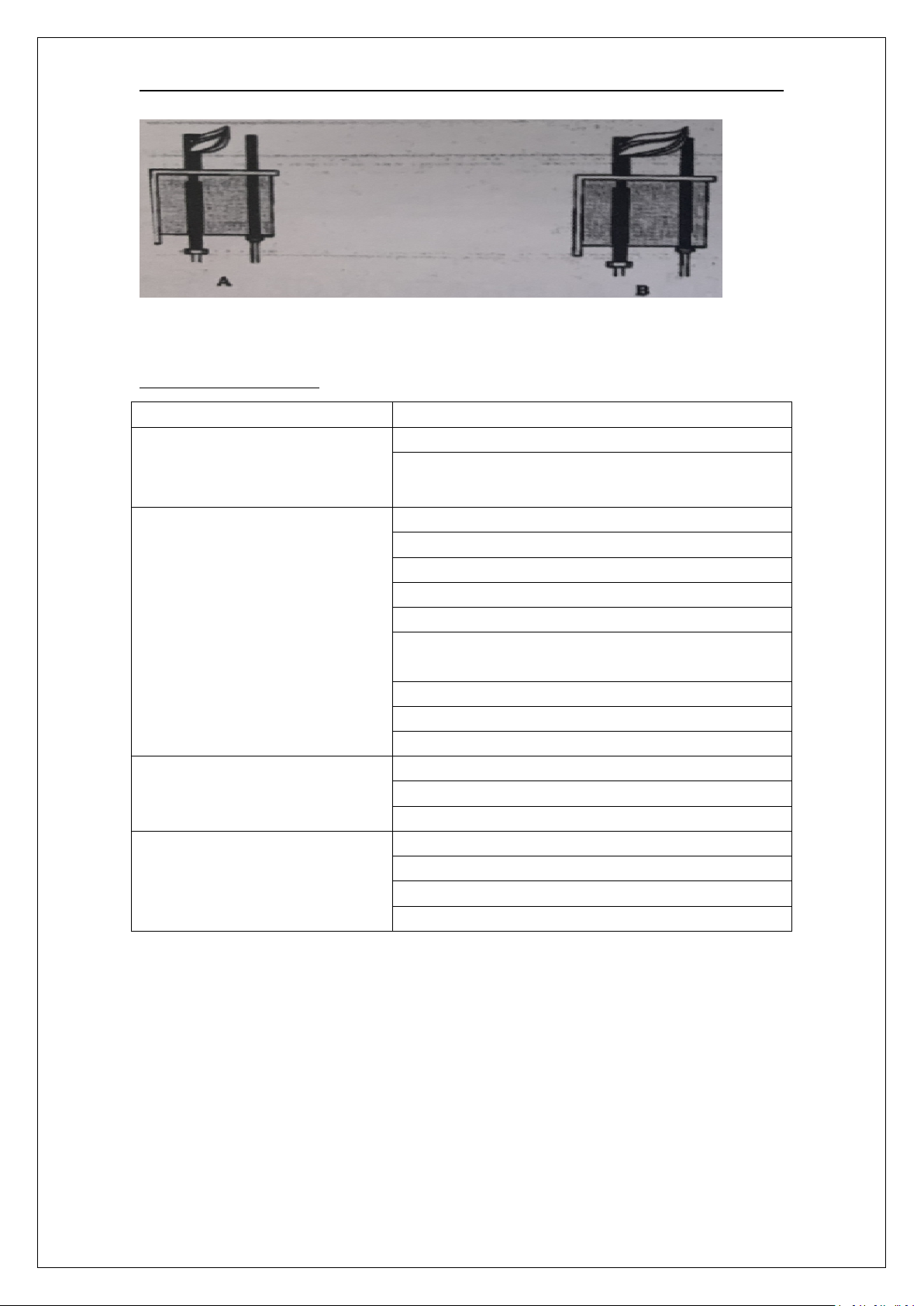
Problem
Likely Cause
Burners do not come on
Gas supply to unit off
Combination gas valve is in "OFF" or "PILOT"
position
Pilot not ignited
Thermostat not "ON"
Combination gas valve is in "OFF" position
Pilot gas not adjusted proper
Gas supply to unit off
Bad thermopile
Dirty thermopile connections at combination gas
valve or high limit
Clogged orifice
Air in gas line
Improper ventilation system.
Pilot produces carbon deposits
Unit connected to wrong gas supply
Pressure not adjusted correctly
Pilot gas not adjusted correctly
Burners produce carbon
deposits
Wrong size orifices
Connected to wrong gas supply
Pressure not adjusted correctly
Flue obstructed
3. Replace pilot adjustment cap
TROUBLESHOOTING
NOTE: Vibrations or shock caused by shaking or pounding baskets on top surface or
by slamming door may cause Hi-Limit Control Switch to open. If this condition
persists, additional cushioning may be added to the rubber grommets supporting
this control to absorb these shocks
23
Page 24
DUKERS GAS FRYERS
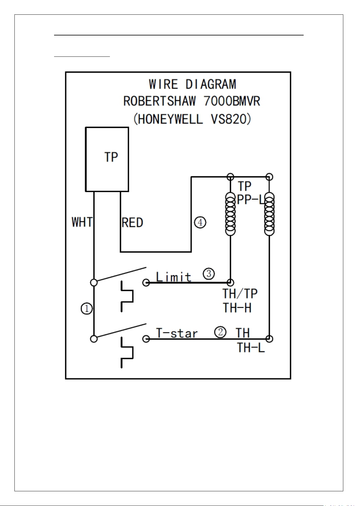
Wiring Diagram
24
Page 25
DUKERS GAS FRYERS
NOTICE
INSTALLATION OF OTHER THAN GENUINE PARTS WILL VOID THE WARRANTY
ON THIS EQUIPMENT
Index of Part Diagrams
Page
Number
Description
24
Gas Parts for 3 tube fryer
25
Gas Parts for 4 tube fryer
26
Gas Parts for 5 tube fryer
PARTS
The serial plate is located inside the front door on the left side
Replacement parts may be ordered either through a Authorized Parts Distributor or a
Authorized Service Agency
25
Page 26
DUKERS GAS FRYERS
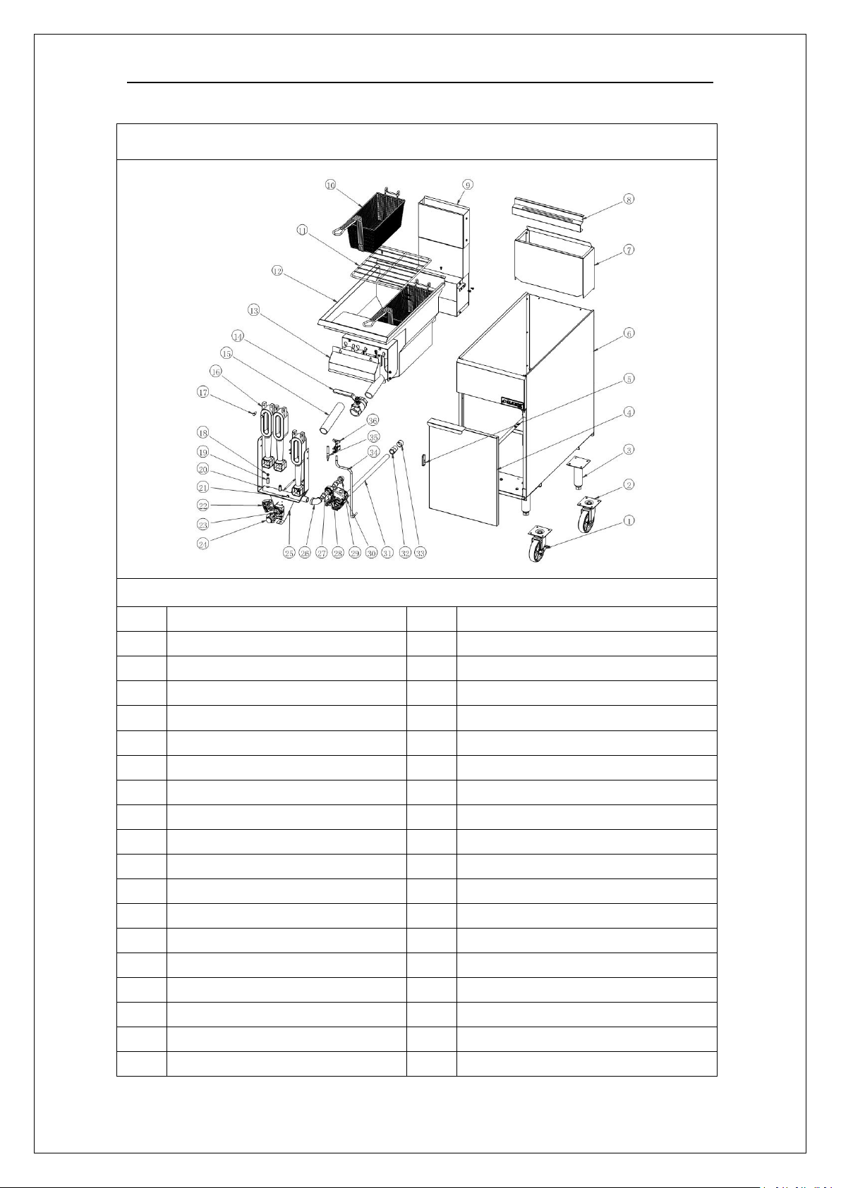
Gas Parts for Fryer(3 tube shown)
DCF3 fryer blast chart
NO.
Description
19
Nozzle Screw
1
5" Casters for unit with break
20
Manifold Assembly
2
5" Casters for unit with no break
21
Plugs
3
Stainless cone leg,H=6"~7"
22
Safety Hi Limit
4
Door components
23
Thermostat
5
Magnets for the doors
24
Thermostat Knobs
6
Outer cabinet
25
Braket for thermostat
7
Flue Deflector
26
Reducing elbow from
8
Fried basket hanging board
27
Inner joint
9
Flue components
28
Union
10
Fry Basket
29
Inside and outside elbow
11
Basket Screen
30
Milivolt Gas Valve
12
Tank
31
Gas Supply Pipe
13
Burner Deflector
32
Adapters
14
Drain Valve
33
Pipe cap
15
Drain Line Pipe
34
Pilot Gas Line
16
Cast Iron Burners
35
Thermalpile
17
Hex Bolts
36
Pilot Assembly
18
Orifice
26
Page 27
DUKERS GAS FRYERS
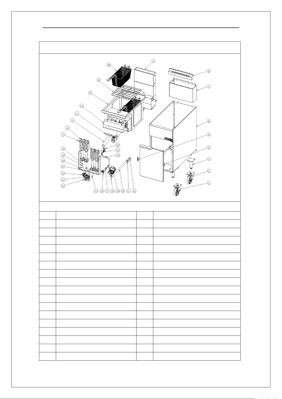
Gas Parts for Fryer(4 tube shown)
DCF4 fryer blast chart
NO.
Description
18
Orifice
1
5" Casters for unit with break
19
Nozzle Screw
2
5" Casters for unit with no break
20
Manifold Assembly
3
Stainless cone leg,H=6"~7"
21
Plugs
4
Door components
22
Safety Hi Limit
5
Magnets for the doors
23
Thermostat
6
Outer cabinet
24
Thermostat Knobs
7
Flue Deflector
25
Braket for thermostat
8
Fried basket hanging board
26
Inner joint
9
Flue components
27
Union
10
Fry Basket 165×340×157
28
Inside and outside elbow
11
Basket Screen 344×342
29
Milivolt Gas Valve
12
Tank
30
Gas Supply Pipe
13
Burner Deflector
31
Adapters
14
Drain Valve
32
Pipe cap
15
Drain Line Pipe
33
Pilot Gas Line
16
Cast Iron Burners
34
Thermalpile
17
Hex Bolts
35
Pilot Assembly
27
Page 28
DUKERS GAS FRYERS
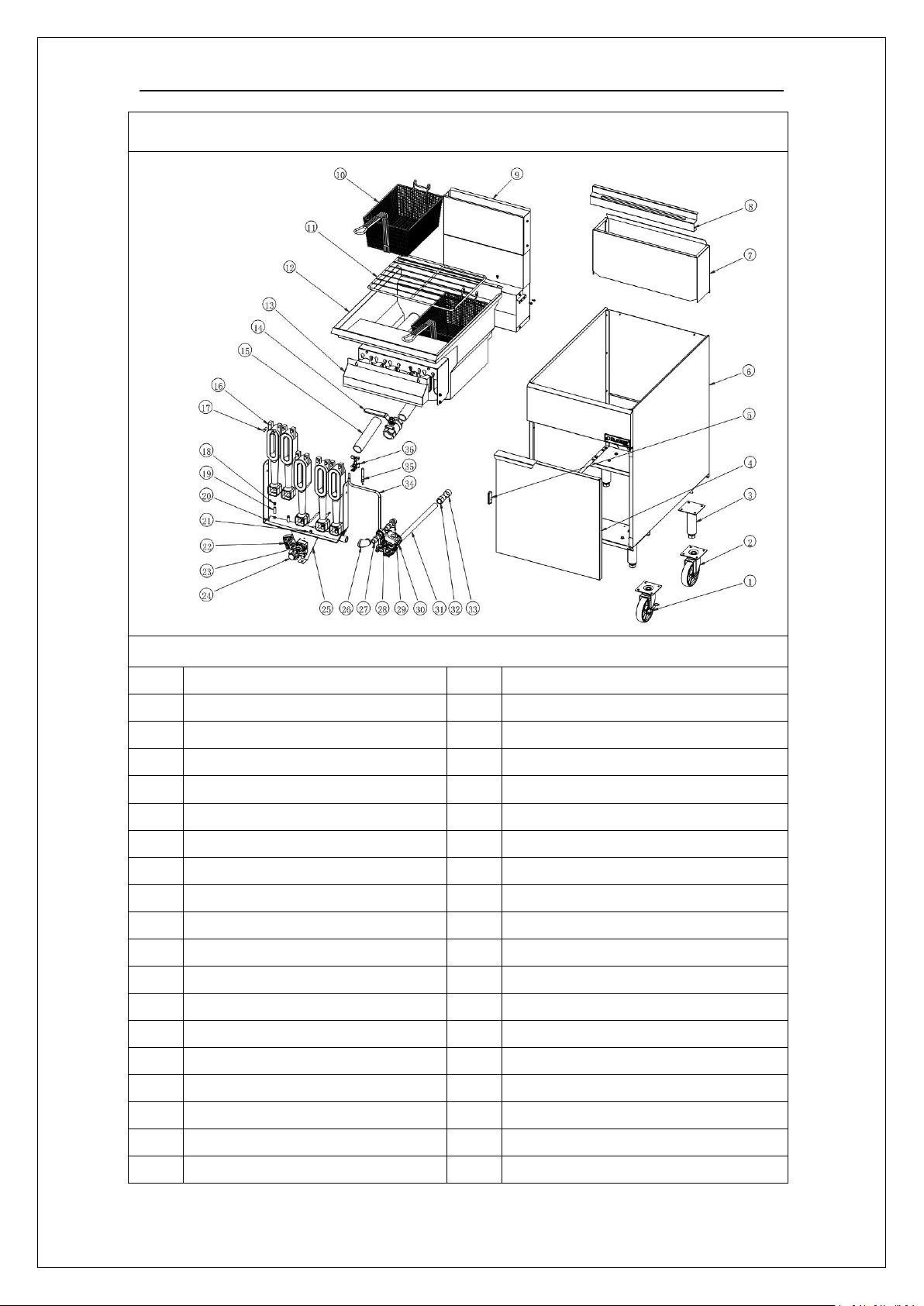
Gas Parts for Fryer(5 tube shown)
DCF5 fryer blast chart
NO.
Description
19
Nozzle Screw
1
5" Casters for unit with break
20
Manifold Assembly
2
5" Casters for unit with no break
21
Plugs
3
Stainless cone leg,H=6"~7"
22
Safety Hi Limit
4
Door components
23
Thermostat
5
Magnets for the doors
24
Thermostat Knobs
6
Outer cabinet
25
Braket for thermostat
7
Flue Deflector
26
Reducing elbow from
8
Fried basket hanging board
27
Inner joint
9
Flue components
28
Union
10
Fry Basket
29
Inside and outside elbow
11
Basket Screen
30
Milivolt Gas Valve
12
Tank
31
Gas Supply Pipe
13
Burner Deflector
32
Adapters
14
Drain Valve
33
Pipe cap
15
Drain Line Pipe
34
Pilot Gas Line
16
Cast Iron Burners
35
Thermalpile
17
Hex Bolts
36
Pilot Assembly
18
Orifice
28
Page 29
DUKERS GAS FRYERS
A product with the DUKERS name incorporates the best in durability and low
maintenance. We all recognize, however, that replacement parts and occasional
professional service may be necessary to extend the useful life of this unit. When
service is needed, contact a DUKERS Authorized Service Agency, or your dealer. To
avoid confusion, always refer to the model number, serial number, and type of your
unit
DUKERS FRYER
29
Page 30

DUKERS GAS FRYERS
LIMITED ORIGINAL COMMERCIAL EQUIPMENT WARRANTY FOR THE GAS FRYERS
DUKERS warrants the Gas Fryer to be free of defects in materials and workmanship
for a period of 1 year from the date of original installation
This Warranty is subject to the the following conditions and limitations:
1. This warranty is limited to product(s) sold by DUKERS to the original user in the
continental United States and Canada.
2. Original installation must occur within 18 months of date of manufacture, and
proof of the installation must Canada be provided to DUKERS.
3. The liability of DUKERS is limited to the repair or replacement of any part found
to be defective.
4. DUKERS will bear normal labor charges incurred in the repair or replacement of a
warranted piece of equipment within 50 miles (80 kilometers) of an authorized
service agency. Time and travel charges in excess of 50 miles (80 kilometers)will
be the responsibility of the person or firm requesting the service
5. This warranty does not apply to any product(s) which have not been installed in
accordance with the directions published in the appropriate installation and
operation manuals. DUKERS will bear no responsibility or liability for any
product(s)which have been mishandled, abused, misapplied, misused, subject
to harsh chemical action, (chlorinated or sulfate products), or poor water quality,
field modified by unauthorized personnel, damaged by flood, fire, or other acts
of nature, or which have altered or missing serial numbers.
6. DUKERS does not recommend or authorize the use of any product(s) in a
non-commercial application, including but not limited to residential use. The use
or installation of product(s) in non-commercial applications renders all
warranties, expressed or implied, including the warranties of MERCHANTABILITY
and FITNESS FOR A PARTICULAR PURPOSE, null and void, including any
responsibility for damage, cost and legal actions re suiting from the use or
installation of product(s) in any non-commercial setting
7. Adjustments such as calibrations, leveling, tightening of fasteners or utility
connections normally associated with original installation are the responsibility
of the installer and not that of DUKERS
8. Exception to the 1 year warranty period is as listed:
Fry Tanks:
If tank is found to be leaking within the first year of operation from
date of installation and verified by an authorized service agency, the
entire fryer will be replaced. Replacement fryer will be warranted for
the balance of the original warranty. Original purchased replacement
parts manufactured by DUKERS Will be warranted for 90 days from the
parts invoice date. This warranty is or parts cost only, and does not
include freight or labor charges. Exceptions are stainless steel fr tanks
which will be warranted as stated in item
9. This states the exclusive remedy against DUKERS relating to the product(s),
30
Page 31

DUKERS GAS FRYERS
whether in contract or in tort or under any other legal theory, and whether
arising out of warranties, representations, instructions, installations or defects
from any cause. DUKERS shall not be liable, under any legal theory, for loss of
use, revenue or profit, or for substituted use or performance, or for incidental,
indirect, or special or consequential damages or for any other loss of cost of
similar type
10. THIS WARRANTY AND THE LIABILTIES SET FORTH HEREIN ARE EXCLUSIVE AND IN
LIEU OF ALL OF THEIRLIABILITES AND WARRANTIES, EXPRESSED OR IMPLIED,
INCLUDING BUT NOT LIMITED TO, IMPLIED WARRANTIES OR MERCHANTABILITY
AND FITNESS FOR PARTICULAR PURPOSE AND CONSTITUTES THE ONLY
WARRANTY OF DUKERS WITH RESPOECT TO THE PRODUCT(S)
DUKERS APPLIANCE CO., USA LTD
TOLL FREE: 1-800-931-8628 | FAX: 562-801-3026
CORPORATE OFFICE: 2488 PECK ROAD, CITY OF INDUSTRY, CA 90601
WWW.DUKERSUSA.COM
31
 Loading...