

Page 1
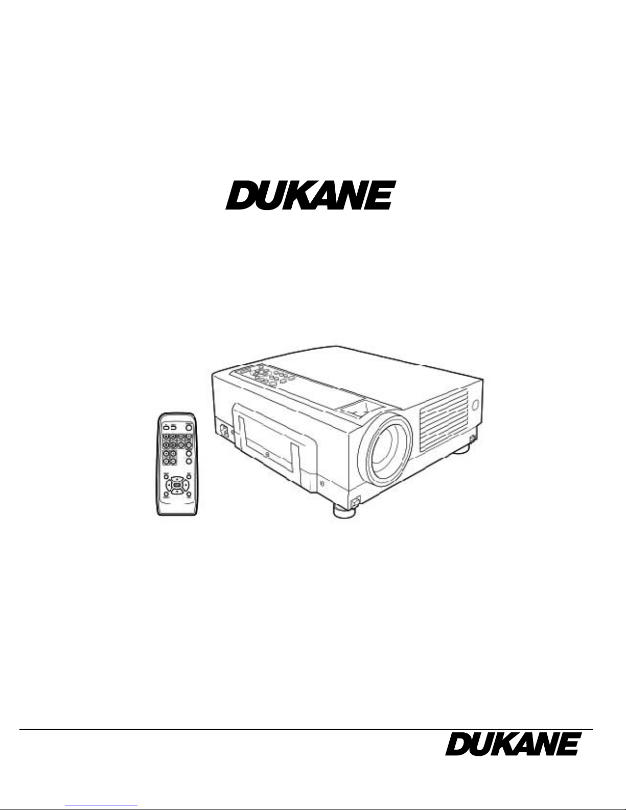
User's Manual
D-ILA Multimedia Projector
Model 28A9017
Audio Visual Products
Page 2
2
SAFETY PRECAUTIONS
About burning-in of the D-ILA device
Do not allow the same still picture to be projected for a long
time or an abnormally bright video picture to be projected.
Do not project video images with high-intensity or high contrast
on a screen. The video image could be burnt into the D-ILA
device.
Use special care when projecting video games or computer program images. There is no problem with ordinary video-cassette
playback images.
About the installation place
Do not install the projector in a place that cannot support its
weight securely.
If the installation place is not sturdy enough, the projector could
fall or overturn, possibly causing personal injury.
IMPORTANT SAFEGUARDS
Electrical energy can perform many useful functions. This unit
has been engineered and manufactured to assure your personal safety. But IMPROPER USE CAN RESULT IN POTEN-
TIAL ELECTRICAL SHOCK OR FIRE HAZARD. In order not
to defeat the safeguards incorporated into this product, observe the following basic rules for its installation,use and service. Please read these “Important Safeguards”carefully before
use.
– All the safety and operating instructions should be read be-
fore the product is operated.
– The safety and operating instructions should be retained for
future reference.
– All warnings on the product and in the operating instructions
should be adhered to.
– All operating instructions should be followed.
– Place the projector near a wall outlet where the plug can be
easily unplugged.
– Unplug this product from the wall outlet before cleaning. Do
not use liquid cleaners or aerosol cleaners. Use a damp cloth
for cleaning.
– Do not use attachments not recommended by the product
manufacturer as they may be hazardous.
– Do not use this product near water. Do not use immediately
after moving from a low temperature to high temperature, as
this causes condensation, which may result in fire, electric
shock, or other hazards.
– Do not place this product on an unstable cart, stand, or table.
The product may fall, causing serious injury to a child or adult,
and serious damage to the product. The product should be
mounted according to the manufacturer’s instructions, and
should use a mount recommended by the manufacturer.
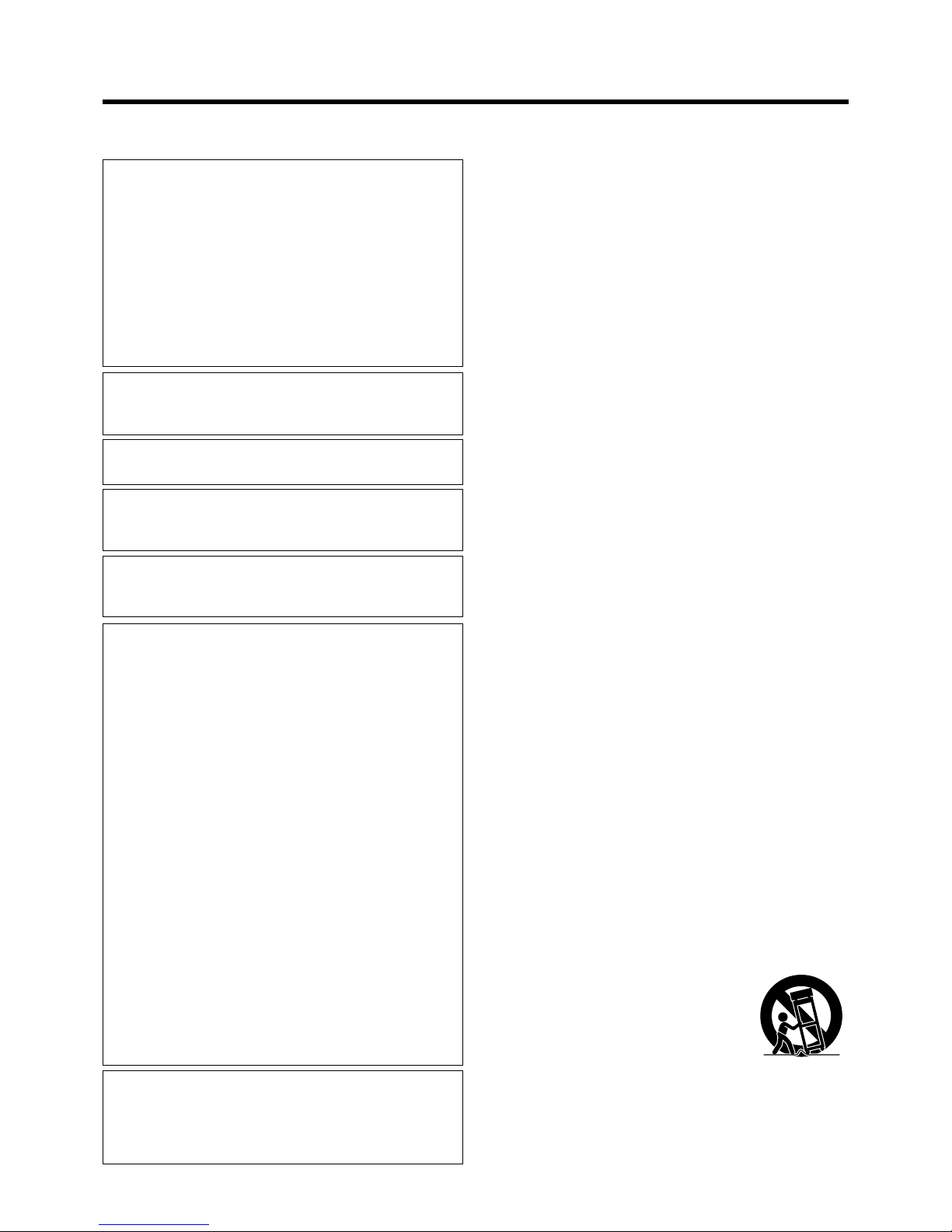
– When the product is used on a cart, care
should be taken to avoid quick stops, ex-
cessive force, and uneven surfaces which
may cause the product and cart to overturn,
damaging equipment or causing possible
injury to the operator.
PORTABLE CART WARNING
(symbol provided by RETAC)
S3126A
IMPORTANT INFORMATION
WARNING :
TO PREVENT FIRE OR SHOCK HAZARDS, DO NOT EXPOSE THIS APPLIANCE TO RAIN OR MOISTURE.
CAUTION :
To reduce the risk of electric shock, do not remove cover.
Refer servicing to qualified service personnel.
This projector is equipped with a 3-blade grounding type
plug to satisfy FCC rule. If you are unable to insert the plug
into the outlet, contact your electrician.
NOTICE (For USA)
Language for Manuals of Products using HID Lamps
(that contains mercury)
This product has a High Intensity Discharge (HID) lamp
that contains a small amount of mercury. It also contains
lead in some components.
Disposal of these materials may be regulated in your
community due to environmental considerations. For
disposal or recycling information please contact your
local authorities, or the Electronics Industries Alliance:
http://www.eiae.org.
WARNING :
THIS APPARATUS MUST BE EARTHED.
MACHINE NOISE INFORMATION (Germany only)
Changes Machine Noise Information Ordinance 3.
GSGV, January 18, 1991: The sound pressure level at the
operator position is equal or less than 70 dB(A) according
to ISO 7779.
FCC INFORMATION (U.S.A. only)
CAUTION:
Changes or modification not approved by JVC could void
the user’s authority to operate the equipment.
NOTE:
This equipment has been tested and found to comply with
the limits for a Class B digital devices, pursuant to Part 15 of
the FCC Rules. These limits are designed to provide reasonable protection against harmful interference in a residential installation. This equipment generates, uses, and can
radiate radio frequency energy and, if not installed and used
in accordance with the instructions, may cause harmful interference to radio communications. However, there is no
guarantee that interference will not occur in a particular installation. If this equipment does cause harmful interference
to radio or television reception, which can be determined by
turning the equipment off and on, the user is encourage to
try to correct the interference by one or more of the following measures:
• Reorient or relocate the receiving antenna.
• Increase the separation between the equipment and receiver.
• Connect the equipment into an outlet on a circuit different
from that to which the receiver is connected.
• Consult the dealer or an experienced radio/TV technician
for help.
Page 3
3
– Slots and openings in the cabinet are provided for ventilation.
These ensure reliable operation of the product and protect it
from overheating. These openings must not be blocked or
covered. (The openings should never be blocked by placing
the product on bed, sofa,rug, or similar surface. It should not
be placed in a built-in installation such as a bookcase or rack
unless proper ventilation is provided and the manufacturer’s
instructions have been adhered to.)
For proper ventilation, separate the product from other equipment, which may prevent ventilation and keep a distance of
more than 11-7/8” (30 cm).
– This product should be operated only with the type of power
source indicated on the label. If you are not sure of the type of
power supply to your home, consult your product dealer or
local power company.
– This product is equipped with a three-wire plug. This plug will
fit only into a grounded power outlet. If you are unable to insert the plug into the outlet, contact your electrician to install
the proper outlet. Do not defeat the safety purpose of the
grounded plug.
–Power-supply cords should be routed so that they are not
likely to be walked on or pinched by items placed upon or
against them. Pay particular attention to cords at doors, plugs,
receptacles, and the point where they exit from the product.
–For added protection of this product during a lightning storm,
or when it is left unattended and unused for long periods of
time, unplug it from the wall outlet and disconnect the cable
system. This will prevent damage to the product due to lightning and power line surges.
– Do not overload wall outlets, extension cords, or convenience
receptacles on other equipment as this can result in a risk of
fire or electric shock.
–Never push objects of any kind into this product through open-
ings as they may touch dangerous voltage points or short out
parts that could result in a fire or electric shock.
Never spill liquid of any kind on the product.
– Do not attempt to service this product yourself as opening or
removing covers may expose you to dangerous voltages and
other hazards. Refer all service to qualified service personnel.
– Unplug this product from the wall outlet and refer service to
qualified service personnel under the following conditions:
a) When the power supply cord or plug is damaged.
b) If liquid has been spilled, or objects have fallen on the prod-
uct.
c) If the product has been exposed to rain or water.
d) If the product does not operate normally by following the
operating instructions. Adjust only those controls that are
covered by the Operation Manual, as an improper adjust-
ment of controls may result in damage and will often re-
quire extensive work by a qualified technician to restore
the product to normal operation.
e) If the product has been dropped or damaged in any way.
f ) When the product exhibits a distinct change in performance
- this indicates a need for service.
– When replacement parts are required, be sure the service
technician has used replacement parts specified by the manufacturer or with same characteristics as the original part. Unauthorized substitutions may result in fire, electric shock, or
other hazards.
– Upon completion of any service or repairs to this product, ask
the service technician to perform safety checks to determine
that the product is in proper operating condition.
– The product should be placed more than one foot away from
heat sources such as radiators, heat registers, stoves, and
other products (including amplifiers) that produce heat.
– When connecting other products such as VCR’s, and per-
sonal computers, you should turn off the power of this product for protection against electric shock.
– Do not place combustibles behind the cooling fan. For ex-
ample, cloth, paper, matches, aerosol cans or gas lighters
that present special hazards when over heated.
– Do not look into the projection lens while the illumination lamp
is turned on. Exposure of your eyes to the stronglight can
result in impaired eyesight.
– Do not look into the inside of this unit through vents (ventila-
tion holes), etc. Do not look at the illumination lamp directly
by opening the cabinet while the illumination lamp is turned
on. The illumination lamp also contains ultraviolet rays and
the light is so powerful that your eyesight can be impaired.
– Do not drop, hit, or damage the light-source lamp (lamp unit)
in any way. It may cause the light-source lamp to break and
lead to injuries. Do not use a damaged light source lamp. If
the light-source lamp is broken, ask your dealer to repair it.
Fragments from a broken light-source lamp may cause injuries.
– The light-source lamp used in this projector is a high pres-
sure mercury lamp. Be careful when disposing of the lightsource lamp. If anything is unclear, please consult your dealer.
– Do not “ceiling-mount” the projector to a place which tends to
vibrate; otherwise, the attaching fixture of the projector could
be broken by the vibration, possibly causing it to fall or overturn, which could lead to personal injury.
– Use only the accessory cord designed for this product to pre-
vent shock.
The power supply voltage rating of this product is AC 120 V,
AC 100 V– AC 240 V, the power cord attached conforms to
the following power supply voltage. Use only the power cord
designated by our dealer to ensure Safety and EMC.
When it is used by other power supply voltage, power cable
must be changed.
Ensure that the power cable used for the projector is the correct type for the AC outlet in your country.
Consult your product dealer.
*DO NOT allow any unqualified person to install the unit.
Be sure to ask your dealer to install the unit (eg. attaching it
to the ceiling) since special technical knowledge and skills
are required for installation.
If installation is performed by an unqualified person, it may
cause personal injury or electrical shock.
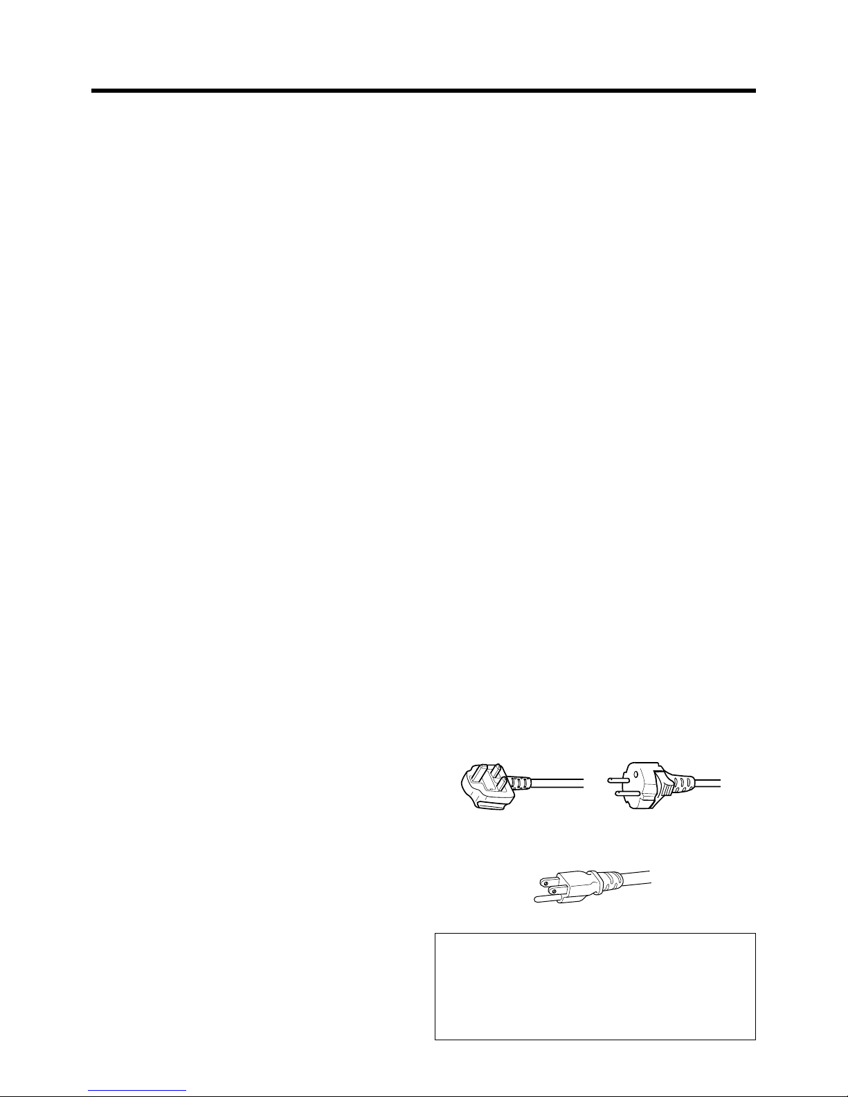
Power cord
For United Kingdom
For European
continent countries
Power cord
Power supply voltage: AC 120 V
Safety Precaution
Page 4
4
Safety Precaution
The wire which is coloured green-and-yellow must be connected
to the terminal which is marked with the letter E or the safety
earth or coloured green or green-and-yellow.
The wire which is coloured blue must be connected to the terminal which is marked with the letter N or coloured black.
The wire which is coloured brown must be connected to the
terminal which is marked with the letter L or coloured red.
When replacing the fuse, be sure to use only a correctly rated
approved type, re-fit the fuse cover.
IF IN DOUBT —— CONSULT A COMPETENT ELECTRICIAN.
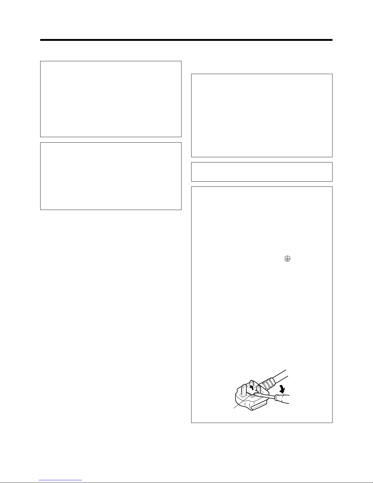
How To Replace The Fuse
Open the fuse compartment with the blade screwdriver, and
replace the fuse.
(* An example is shown in the illustration below.)
WARNING :
THIS APPARATUS MUST BE EARTHED. IMPORTANT:
The wires in the mains lead on this product are coloured in
accordance with the following cord:
Green-and-yellow : Earth
Blue : Neutral
Brown : Live
As these colours may not correspond with the coloured making identifying the terminals in your plug, proceed as follows:
WARNING :
Do not cut off the main plug from this equipment.
If the plug fitted is not suitable for the power points in your
home or the cable is too short to reach a power point, then
obtain an appropriate safety approved extension lead or
adapter or consult your dealer.
If nonetheless the mains plug is cut off, remove the fuse and
dispose of the plug immediately, to avoid a possible shock
hazard by inadvertent connection to the main supply.
If a new main plug has to be fitted, then follow the instruction
given below:
POWER CONNECTION
(United Kingdom only)
WARNING :
Do not cut off the main plug from this equipment.
If the plug fitted is not suitable for the power points in your
home or the cable is too short to reach a power point, then
obtain an appropriate safety approved extension lead or
adapter or consult your dealer.
If nonetheless the mains plug is cut off, remove the fuse and
dispose of the plug immediately, to avoid a possible shock
hazard by inadvertent connection to the main supply.
If a new main plug has to be fitted, then follow the instruction
given below:
WARNING :
THIS APPARATUS MUST BE EARTHED.
IMPORTANT:
The wires in the mains lead on this product are coloured in
accordance with the following cord:
Green-and-yellow : Earth
Blue : Neutral
Brown : Live
As these colours may not correspond with the coloured making identifying the terminals in your plug, proceed as follows:
The wire which is coloured green-and-yellow must be connected to the terminal which is marked with the letter E
or the safety earth or coloured green or green-and-yellow.
The wire which is coloured blue must be connected to the
terminal which is marked with the letter N or coloured black.
The wire which is coloured brown must be connected to the
terminal which is marked with the letter L or coloured red.
When replacing the fuse, be sure to use only a correctly rated
approved type, re-fit the fuse cover.
IF IN DOUBT —— CONSULT A COMPETENT
ELECTRICIAN.
How To Replace The Fuse
Open the fuse compartment with the blade screwdriver, and
replace the fuse.
(* An example is shown in the illustration below.)
Fuse
POWER CONNECTION
Page 5
5
Caution
About burning-in of the D-ILA device
● Do not allow the same still picture to be projected for a long
time or an abnormally bright video image to be projected.
Do not project video images with high-intensity or high contrast on a screen. The video image could be burnt into the
D-ILA device.
Use special care when projecting video games or computer
program images.
There is no problem with ordinary video cassette playback
images.
Viewing conditions
● Brightness of the room
Please avoid having sunshine or light shine directly onto the
screen. Images can only be well projected if the room is dark.
● Do not view the screen continually for a long time
Looking at the screen continually for a long time will cause
your eyes to be tired. Please rest your eyes sometimes.
● Image flicker due to installation condition or the environment
Please do not view flickering images for too long as this causes
poor eyesight.
Care
● Dirt in the cabinet
Please wipe the cabinet clean with a soft cloth. In case of
heavy soiling, please wipe it with a damp cloth soaked with a
neutral detergent.
● Since the cabinet may in time, get damaged or deteriorate in
condition, (eg. peeling paint):
• Do not wipe with a stiff cloth.
• Do not wipe with force.
• Do not wipe with thinner or benzene.
• Do not spray chemicals like insecticide.
• Do not allow it to come into contact with rubber or vinyl ma-
terials for an extended period of time.
● Cleaning the lens
• Please use lens-cleaning paper (of the kind for cleaning spec-
tacles, cameras etc) sold in the market for cleaning.
• Please do not use liquid-type cleansers as it may cause the
coating mask on the surface to peel off.
• Please do not knock the surface of the lens as it damages
easily.
Using the screen mode switch function
• This projector is equipped with a screen mode switch function that sets the screen size (aspect ratio and resize). If the setted
screen aspect ratio and size differs from that of the inputted images (eg images from TV programs), the projected image
screen will differ from the original. Please bear this in mind when you choose the screen mode.
• Please keep in mind that making use of the screen mode switch function to alter screen images(aspect ratio and resize) in
restaurants/ hotels etc, for public viewing, in the pursuit of profit may constitute an infringement of the Copyright Act.
Page 6
6
Contents
SAFETY PRECAUTIONS ............................................ 2
Caution ........................................................................ 5
Accessories ................................................................ 6
Controls and Features ............................................... 7
Front Side / Top Surface / Left Side ....................................... 7
Rear Side / Right Side / Bottom Surface ................................8
Connector Panel .................................................................... 9
Control Panel on the Projector ............................................. 10
Indicator Display on the Control Panel ................................ 10
Remote Control Unit ............................................................. 12
Loading Batteries into the Remote Control ..........................14
Installing the Projector ............................................ 15
Precautions for Installation ................................................... 15
Installing the Projector against the Screen .......................... 16
Mounting the Projector ......................................................... 16
Projection Distance and Screen Size................................... 17
Effective Range and Distance of the
Remote Control Unit ............................................................. 18
Connecting to Various Devices ............................... 19
Signals that can be input into the Projector .........................19
Connecting to Devices......................................................... 21
Connecting the Power Cord (supplied) ............................... 24
Basic Operations...................................................... 25
Basic Operation Procedures................................................ 25
1. Power On ......................................................................25
2. Selecting the image to be projected ............................ 25
3. Adjusting the Zoom Ring (the screen size) .................. 26
4. Adjusting the Focus Ring(Focus) ................................. 26
5. Adjusting the Sound Volume ........................................ 27
Power Off ..........................................................................27
Frequently used Convenient Functions ............................... 28
Enlarging the Image......................................................... 28
Turning Off Image and Sound .......................................... 29
Displaying a Still Picture .................................................. 29
Removing the Trapezoidal Distortion of the Image ..........30
Using the Quick Alignment function ................................ 31
Selecting the Screen Size ................................................31
Adjustments and Settings Using Menus ............... 32
The Menu Structure.............................................................. 32
The Menu Operation Buttons ...............................................35
The Procedure for Menu Operation ..................................... 36
The Menu Configuration....................................................... 37
1 Image adj. menu .......................................................... 37
2 Color temp. menu ........................................................ 37
3 Set up menu ................................................................ 37
4 Position menu .............................................................. 38
5 Decoder menu .............................................................38
6 Logo menu ................................................................... 38
7 Capture menu .............................................................. 38
8 Capture start ................................................................39
9 Option menu (q) ......................................................... 39
p Color profile menu ....................................................... 39
w Language menu .......................................................... 39
e Information menu .........................................................40
Editing and Projecting Logo ................................... 41
Replacing the Lamp ................................................. 43
The light source lamp and its lamp time .............................. 43
The procedure for lamp replacement ..................................43
Resetting the lamp time ....................................................... 45
Cleaning and Replacing the Filter .......................... 46
Troubleshooting ....................................................... 47
What to do when these messages are displayed.. 49
Warning Indication ................................................... 51
Specifications ........................................................... 52
Accessories
The following accessories are packed together with this projector.
Please confirm all items. If any item is missing, please contact your dealer.
Power Cord (approximately 2.5m)....................................................................................................... x 1
Remote Control (RM-MSX21) ............................................................................................................. x 1
[AA/R6-size] Battery (for operation confirmation)................................................................................ x 2
Computer Cable (approximately 2m: D-sub3 row 15 pin) ................................................................... x 1
AV connection cable (approximately 2m: RCA Pin Plug) .................................................................... x 1
Optional Accessories
❈ Please ask your authorized dealer for the details.
• Replacement lamp (lamp unit) BHL5006-S
• Replacement filter
Inner filter : LC32058-001
Lower filter : LC32087-001
Page 7
7
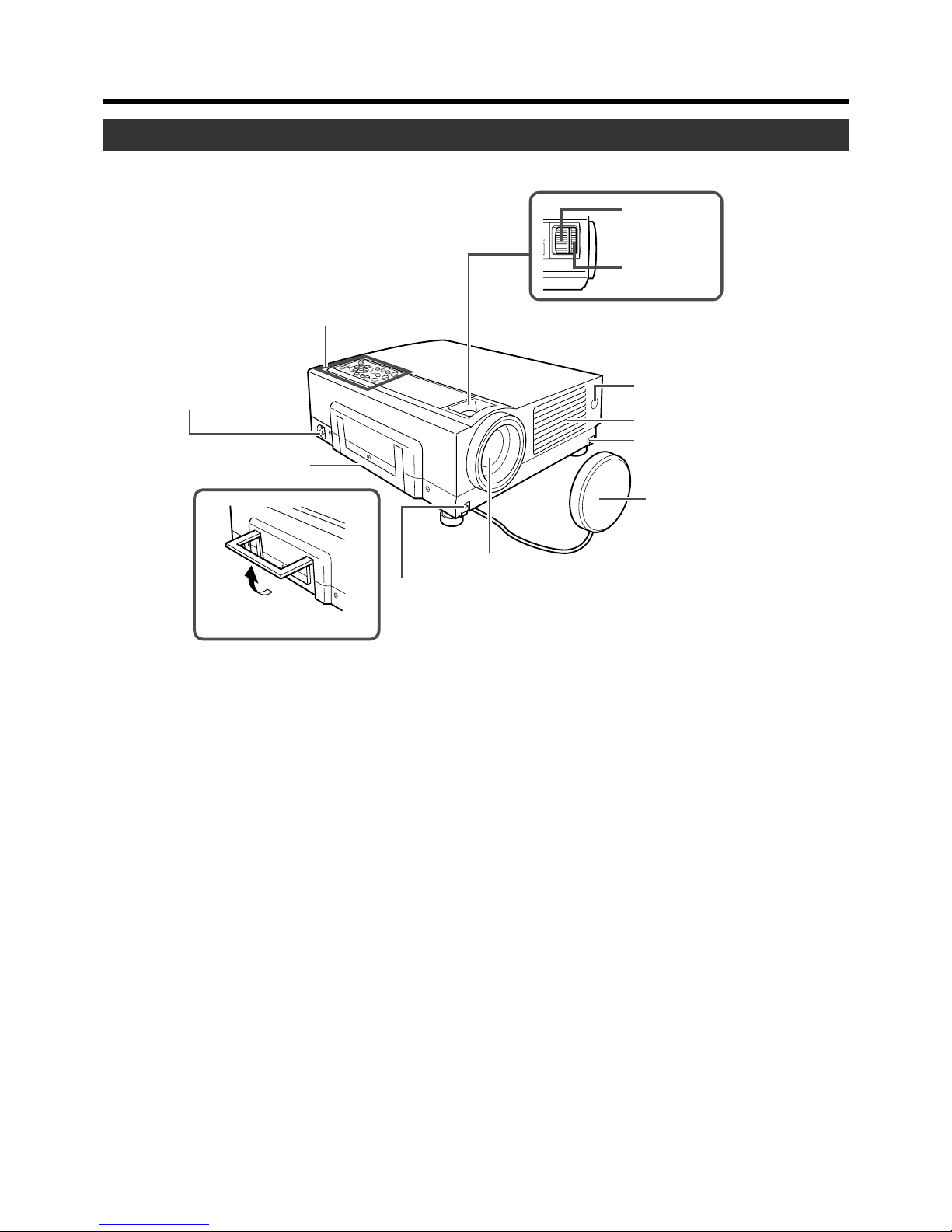
2
AC Power Input
Terminal
3
Carrying Handle
1
Control Panel
8
Remote Sensor (Front)
p
Zoom Ring
9
Focus Ring
7
Exhaust Vents
4
Foot Lever
(for front adjustable foot)
6
Lens Cap
5
Lens
4
Foot Lever
(for front adjustable foot)
Using the Carrying Handle
Controls and Features
Front Side/ Top Surface/ Left Side
7 Air inlets (on the front, right, and bottom side of
projector)
The air inlets absorb air to cool the internal components of
the projector. Do not block or allow warm air to blow into
them as it may cause damage.
* The air inlet filter on the right side cannot be removed.
Please clean the filter regularly with, for example, a
vacuum cleaner.
8 Remote Sensor (Front)
When operating with the remote control, aim it towards this
sensor. (☞ page 18)
*A remote sensor is also provided at the rear of the projec-
tor.
9 Focus Ring
Used to manually focus the projected image on the screen.
p Zoom Ring
Used to manually zoom the projected image on the screen.
1 Control Panel
For details, See ‘Control Panel on the Projector’.
(☞ page 10, 11)
2 AC Power Input Terminal
This is where the supplied power cord is connected to.
(☞ page 24)
3 Carrying Handle
Use this handle when carrying the projector.
4 Foot Lever (for front adjustable foot)
Use when extending and retracting the front foot.
(☞ page 15)
5 Lens
The lens is a 1.3 x manual zoom lens.
Before projection, remove the lens cap. (• page 17, 24)
6 Lens Cap
It is recommended that the cap be fitted on the lens to prevent it from becoming dirty when the projector is not in use.
(☞ page 24)
Page 8
8
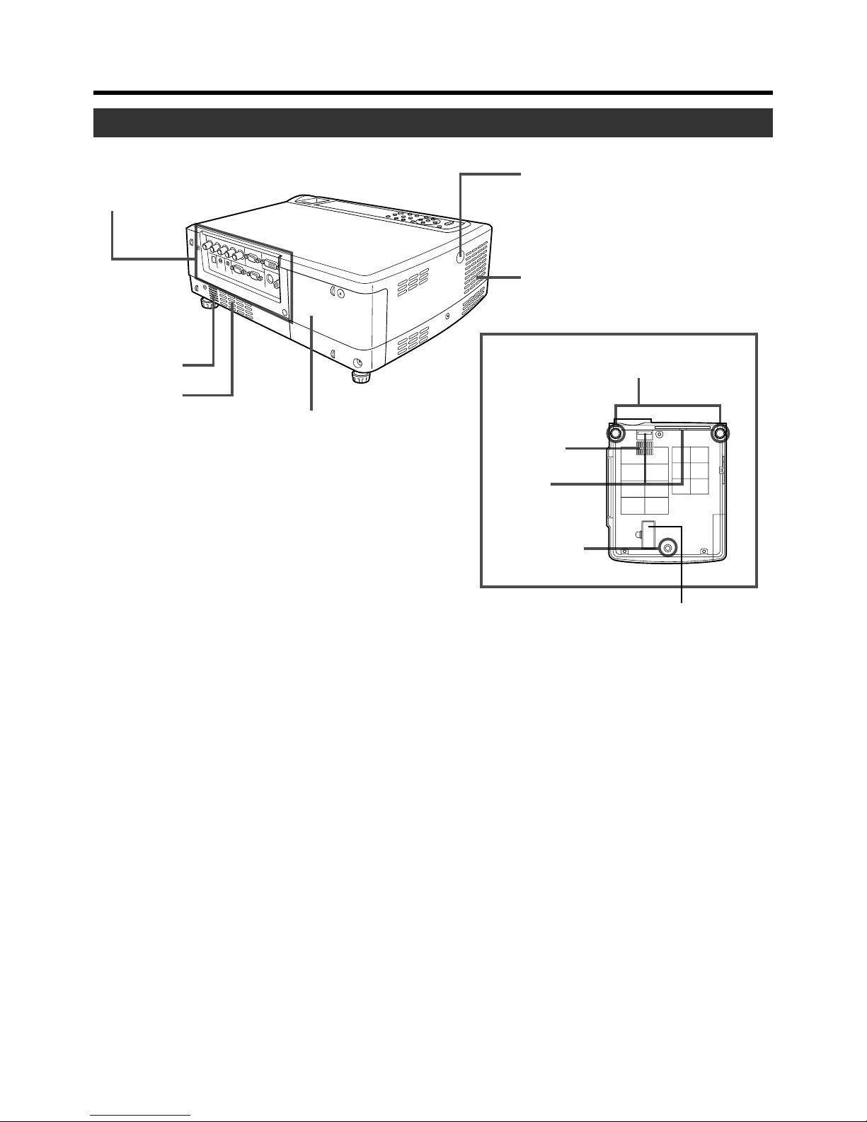
q Connector Panel
u Filter
7 Air Inlet
w Speaker
e Lamp Cover
t Remote Sensor (Rear)
r Exhaust Vents
y Front Adjustable
Foot
i Rear Fixed
Foot
Blocked as it is not in use.
Opening it forcibly will cause
damage to the machine.
Bottom Surface
7 Air Inlet
Rear Side/ Right Side/ Bottom Surface
Controls and Features
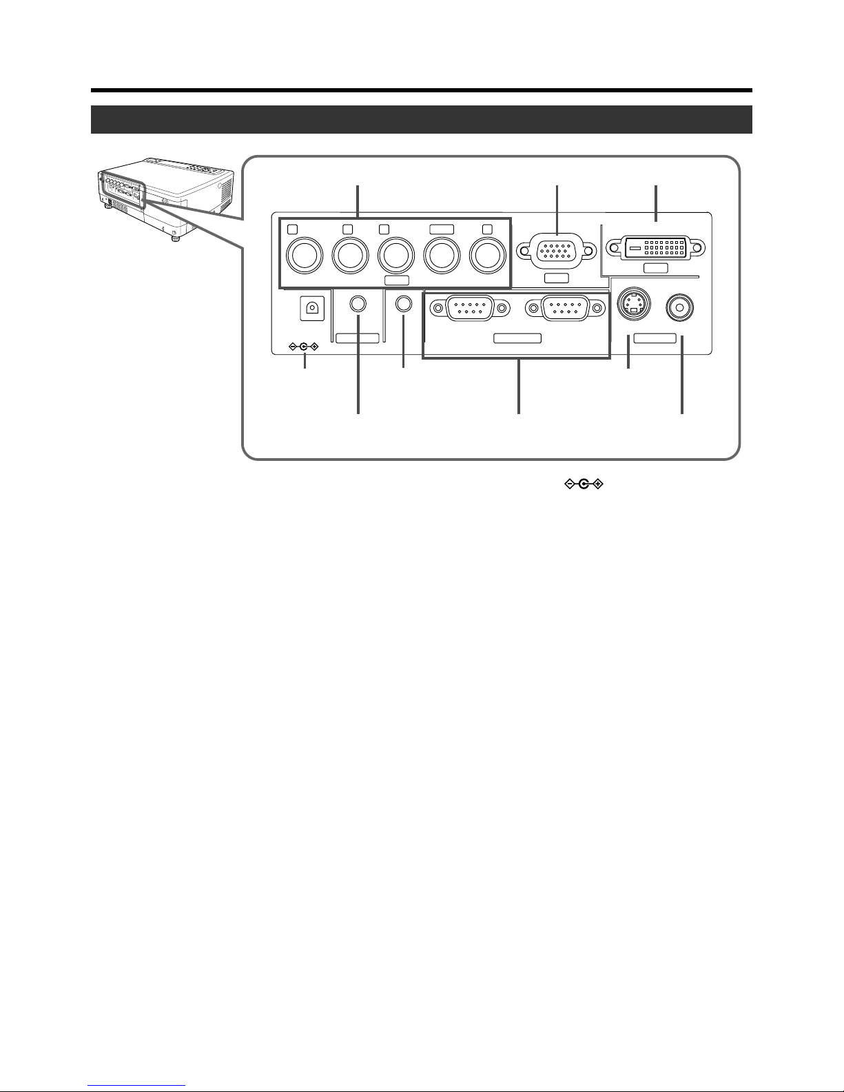
q Connector Panel
For details, refer to ‘Connector Panel’ . (☞ page 9)
w Speaker
Built-in speaker located here.
e Lamp Cover
Remove this cover when replacing the lamp. (☞ page 43)
r Exhaust Vents
Warm air is expelled through these vents to keep the system cool. Please do not block the exhaust vents.
t Remote Sensor (Rear)
When operating with the remote control, aim it towards this
sensor. (☞ page 18)
*A remote sensor is also provided at the front of the projec-
tor.
y Front Adjustable Foot (for adjusting the height and
angle)
It is set at the lowest position when shipped from the factory. The foot can be adjusted to a maximum angle of +6°
and a maximum length of 31mm. (☞ page 15)
u Filter
Cleans air drawn in from the air inlet. Please clean the filter
regularly with eg, a vacuum cleaner. (☞ page 46)
i Rear Fixed Foot
Page 9
9
Controls and Features
Connector Panel
2
PC1 Input Terminal
4
DC OUT
Te r minal
6
REMOTE
Te r minal
5
AUDIO Input Terminal
7
CONTROL RS232C
IN/OUT Terminal
9
VIDEO Input
Te r minal
1
PC2 Input Terminal
3
PC3 Input Terminal
8
Y/C Input
Te r minal
R
PR/C
R
G
Y
B
PB/C
S
VDVIH/C
S
PC1
PC3
PC2
AUDIO IN
REMOTE
DC OUT
5V }1.5A
RS-232C OUT RS-232C IN Y/C VIDEO
CONTROL VIDEO IN
1 PC 2 Input terminal [BNC x 5]
These are multipurpose video input terminals that allow input of the following signals: analog RGB signals, vertical
sync (V) signals, and horizontal sync (H) signals /composite signals (Cs). Devices which have analog RGB signal
output terminals can be connected. This terminal can also
be used as an input terminal for component signals
(Y,C
B,CR) or DTV-format (Y, PB,PR) signals. Devices which
have component signals output terminals can be connected.
(☞ page 22)
To use this terminal, the “PC2 (BNC)” item in the “Options”
menu must be set correctly according to the input signals.
(☞ page 39)
* Input of external sync signals is automatically detected.
Detection of H/V signals or Cs signals causes automatic
switching to external sync. The priority order is H/V>Cs.
* When computer signals are input, the uppermost edge of
the image may appear to bow if the sync signal input is a
composite sync (Cs) or G on sync signal. In this case,
please use separate sync signals for vertical sync (V) and
horizontal sync (H).
2 PC 1 input terminal [D-sub 3 rows 15 pin]
This is an input terminal dedicated to computer signals (RGB
Video signals and sync signals).
Connect the display output terminal of the computer to this
terminal. When a Macintosh computer is to be connected,
please use the conversion adapter (sold separately) for Mac.
(☞ page 22)
* When computer signals are input, the uppermost edge of
the image may appear to bow if the sync signal input is a
composite sync (Cs) or G on sync signal. In this case,
please use separate sync signals for vertical sync(V) and
horizontall sync(H).
3 PC 3 input terminal [DVI-D (Dual/ Single) 24 Pin]
This is an input terminal dedicated to computer signals
(DVI-D Terminal Dual/ Single). Connect the display output
terminal of the computer to this terminal.
4 DC OUT Terminal
This is the DC 5V, 1.5A power source output terminal.
Please do not connect this terminal to devices other
than those designated by the manufacturer.
For enquiries pertaining to the designated devices,
please consult with your authorized dealer.
5 AUDIO (audio) input terminal [mini jack]
This is the audio input terminal for devices connected to
PC1, PC2, PC3, Video or Y/C. Connect the audio output
terminal of the device to this terminal. (☞ page 21, 22)
* When PC 1, PC 2, PC3, Video or Y/C input is being se-
lected, the inputted audio signals will be reproduced by
the projector speaker.
(Audio output for this projector is monaural.)
6 REMOTE terminal [stereo mini jack]
When the remote control is unable to work due to rear projection etc., the REMOTE terminal can be used to connect
an external sensor to the projector. The external sensor is
not generally sold. Please check with your authorized dealer.
7 CONTROL RS232C IN/OUT Terminal [D-sub 9 Pin]
This is the RS-232C interface-specific terminal. The projector can be controlled by a computer connected externally. More than one projectors can be controlled using both
the RS-232C IN and OUT terminals. (☞ page 23)
*For details, please check with your dealer.
8 Y/C Input Terminal [Mini DIN 4 PIN]
This is the input terminal for Y/C (S-Video) signals. Connect this terminal to the S-video output terminal of a video
deck, etc. (☞ page 21)
9 VIDEO Input Terminal [RCA pin jack]
This is an input terminal for composite video signals. Connect this terminal to the composite video output terminal of
a VCR, etc. (☞ page 21)
Page 10
10
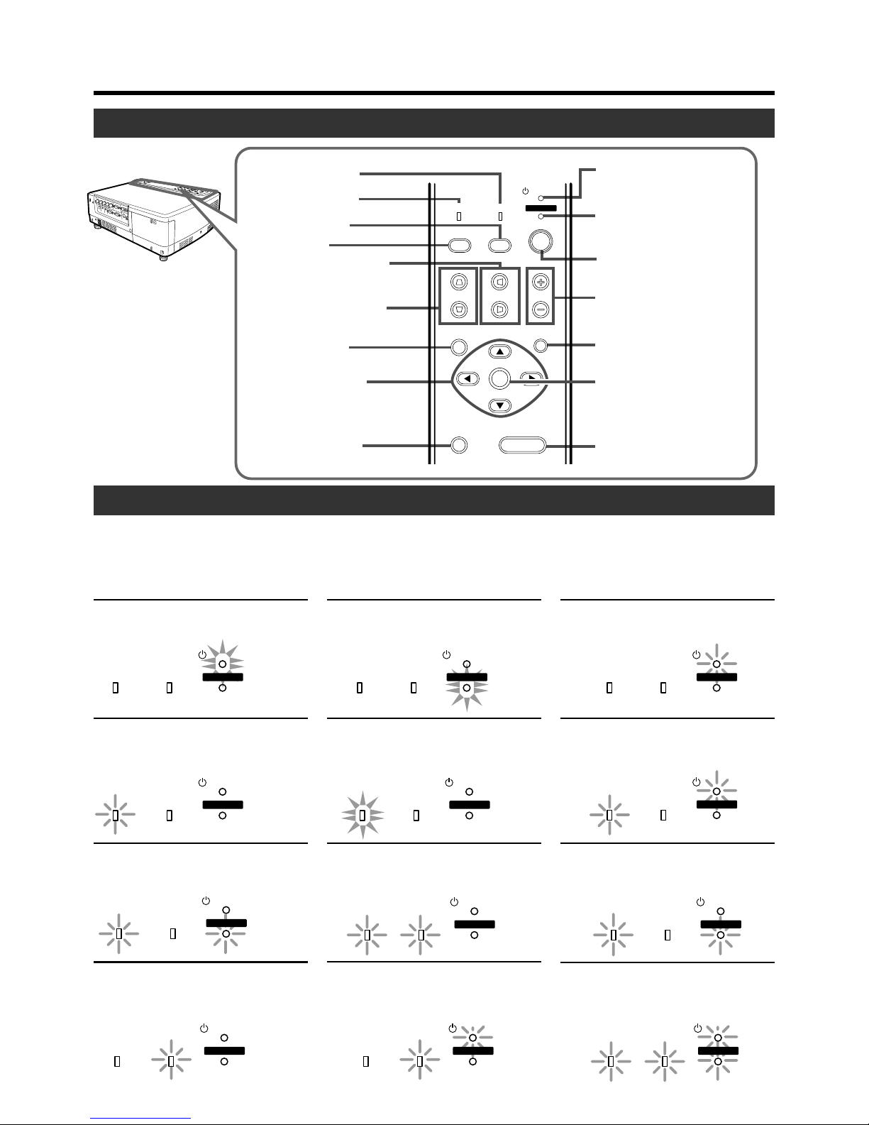
8
TEMP indicator
1
STAND BY indicator
2
OPERATE indicator
3
OPERATE button
4
VOLUME button
5
EXIT button
6
ENTER button
7
HIDE button
p
VIDEO button
q
PC button
w
H-KEYSTONE button
e
V-KEYSTONE button
r
MENU button
t
CURSOR button
(
/
/
/ )
9
LAMP indicator
y
PRESET button
V-KEYSTONE
PC
LAMP
H-KEYSTONE VOL.
VIDEO
TEMP
STAND BY
OPERATE
PRESET
MENU
EXIT
ENTER
HIDE
Control Panel on the Projector
Controls and Features
Indicator Display on the Control Panel
Stand-by, operate and cool down modes, together with other operational activities are indicated by differing combinations of Indicators appearing on the Control Panel.
For explanations on warning indication for *
1,*2
:
*1: ☞ page 43
*
2
: ☞ page 51
STAND BY light on
Projector is in stand by mode
OPERATE light on
Projector is in operate mode
(In operation/ during projection)
STAND BY blinking
Projector is in cool down mode
(when cooling lamp)
LAMP blinking*
1
Lamp life has expired
(Lamp time over 2000hours)
LAMP light on*
1
The time to replace the lamp is near
(Lamp usage time over 1900hours)
LAMP and STAND BY blinking*
2
Lamp does not light up and projector is unable
to project
LAMP and OPERATE blinking
simultaneously*
2
Lamp has turned off during projection
LAMP and TEMP blinking*
2
Circuits are not functioning properly
(Abnormal circuit functioning)
LAMP and OPERATE blinking
alternately*
2
Lamp has been removed
TEMP blinking*
2
Internal temperature is abnormally high
(Abnormal internal temperature)
TEMP and STAND BY blinking*
2
Temperature at exhaust vents is high
(Abnormal external temperature)
All blinking*
2
When inner fan has stopped (fan lock)
LAMP TEMP
STAND BY
OPERATE
LAMP TEMP
STAND BY
OPERATE
LAMP TEMP
STAND BY
OPERATE
LAMP TEMP
STAND BY
OPERATE
LAMP TEMP
STAND BY
OPERATE
LAMP TEMP
STAND BY
LAMP TEMP
STAND BY
OPERATE
LAMP TEMP
STAND BY
OPERATE
OPERATE
LAMP TEMP
STAND BY
OPERATE
LAMP TEMP
STAND BY
LAMP TEMP
STAND BY
OPERATE
LAMP TEMP
STAND BY
OPERATE
OPERATE
Page 11

11
Control Panel on the Projector
Controls and Features
1 STAND BY Indicator
Light on : In stand by mode.
Blinking : In cool down mode.
2 OPERATE Indicator
Light on : During projection.
3 OPERATE button
When this projector is in standby mode, pressing this button for more than 1 second will turn the projector on and
cause the OPERATE indicator to light up. Press it one second or more again, and the projector goes into the cool
down mode and finally into stand by mode. (☞ page 25)
* The OPERATE button will not work within approximately 1
minute of the light-source lamp being turned on. Hence
wait about 1 minute before pressing.
4 VOLUME ª / · buttons
Use these buttons to adjust the sound volume.
(☞ page 27)
5 EXIT button
Press this button to display the previous menu. (For example, from sub menu to main menu). Pressing this button
when the main menu is displayed will erase the menu.
(☞ page 35)
6 ENTER button
Press this button to show the next menu (For example, from
main menu to sub-menu). It is also used when “ENTER” is
displayed against an item on the menu screen, or to choose
the “Reset” option etc. (☞ page 35)
7 HIDE button
Use this button to temporarily halt the audio and video output. Press again to resume. (☞ page 29)
8 TEMP Indicator
Blinking : Indicates the temperature inside the projector is
abnormally high.
9 LAMP Indicator
Light on : Indicates the lamp has been used for more
than1900 hours.
Blinking : Indicates the lamp has been used for more than
2000 hours.
Please change the lamp. (☞ page 10, 43, 51)
p VIDEO button
Use this button to select a device such as a video connected to the VIDEO IN terminal (VIDEO or Y/C Input terminal) of the projector. (☞ page 25)
q PC button
Use this button to select a device connected to the PC1,
PC2 or PC3 terminals. (☞ page 26)
w H-KEYSTONE button
Use this button to remove the horizontal trapezoidal distortion of the image projected on the screen. (☞ page 30)
e V-KEYSTONE button
Use this button to remove the vertical trapezoidal distortion
of the image projected on the screen. (☞ page 30)
r MENU button
Use this button to enter or exit the menu mode. When the
main menu is displayed, pressing this button will cause the
menu to disappear. (☞ page 35)
t CURSOR ( / / / ) buttons
These buttons are used in the menu mode to select an
item and to set or adjust the value in the sub-menu.
(☞ page 35)
y PRESET button
This PRESET button works as a reset button for the
[VOLUME] [V-KEYSTONE] [H-KEYSTONE] adjustments
done on the control panel and remote control and the
[DIGITAL ZOOM] and [SCREEN „] adjustments done on
the remote control. (☞ page 28, 30)
When adjusting the volume, keystone or digital zoom (when
the setting is displayed) the adjusted value is reset to that
which was set when the projector was shipped from the
factory. This button does not work for the items in the menu
(submenu). (☞ page 35)
About Cool Down mode
After projection, the heated lamp will go through a 90 seconds cool-down period known as the cool down mode. This
function is to prevent heat from the heated lamp causing
damage and deformation to the internal components of the
projector. It also prevents lamp breakage and shortened
lamp life.
The Cool down mode is indicated by the blinking STAND
BY indicator. During the cool down mode, pressing the
OPERATE button will not turn on the projector.
After the cool down process is completed, the projector will
automatically change to stand by mode.
Note
Please do not pull out the plug from the power outlet during
cool down mode. Please also do not block the exhaust vents
by standing the projector on its end or laying it on its side.
Page 12
12
QUICK ALIGN.
PC VIDEO
VOLUME
PRESET HIDE
ENTER
MENU EXIT
FREEZE
OPERATE
V-KEYSTONE H-KEYSTONE
SCREEN
DIGITAL
ZOOM
FOCUS
W
S
1
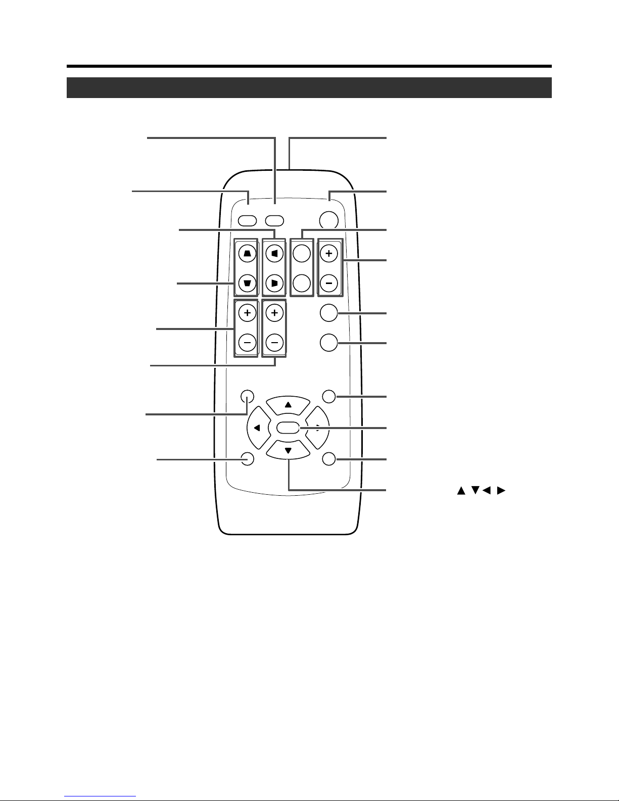
Remote Control’s signal transmitter
2
OPERATE button
q
VIDEO button
w
PC button
e
H-KEYSTONE button
r
V-KEYSTONE button
3
SCREEN button
4
DIGITAL ZOOM button
5
FREEZE button
QUICK ALIGN. (quick alignment)
button
7
EXIT button
p
CURSOR ( ) button
8
ENTER button
9
HIDE button
t
VOLUME button
u
MENU button
FOCUS button
(Only for Fixed Lens Models)
i
PRESET button
// /
y
6
Remote Control Unit
Controls and Features
Page 13

13
Controls and Features
1 Remote Control’s signal transmitter
(☞ page 18)
2 OPERATE button
When the projector is in standby mode, pressing this button for one second or more will turn on the projector and
light up the OPERATE indicator. Press it one second or
more again and the projector will turn off, cool down and
finally enter the standby mode. (☞ page 25)
* The OPERATE button will not work for approximately 1
minute from when the light-source lamp is turned on. Wait
approximately 1 minute before pressing.
3 SCREEN button
Each time you press this button, the selection alternates
between wide screen size (16:9) and standard screen size
(4:3). (☞ page 31)
4 DIGITAL ZOOM ª / · buttons
This digital zoom function can magnify the image by up to
four times on the screen. (☞ page 28)
* There will however be some inevitable loss of image qual-
ity when images are enlarged.
5 FREEZE button
This button allows the image to be retained in the projector
memory and stills the picture on the screen. Press the button once to freeze the picture and again to de-freeze.
(☞ page 29)
6 QUICK ALIGN. (quick alignment) button
Use this button to automatically adjust the projected image’s (i)horizontal and vertical position, (ii) Width and display area, etc. During alignment, the message “Quick
Alignment” appears on the screen and disappears when
alignment is complete. (☞ page 31)
* The ‘Quick Alignment’ function only works when the sig-
nal is input from either the PC1 or PC2 terminal. It does
not work when the signal is input from the VIDEO IN terminal or the Y/C input terminal.
7 EXIT button
Press this button to display the previous hierarchical menu
(For example, from sub-menu to main menu). When the
main menu is displayed, pressing this button will cause the
menu to disappear. (☞ page 35)
8 ENTER button
Press this button to show the next hierarchical menu (For
example, from main menu to sub menu). It is also used
when “ENTER” is displayed against the item on the menu
screen or to select the “Reset” menu. (☞ page 35)
9 HIDE button
Use this button to temporarily halt the audio and visual output. Press again to resume.
(☞ page 29)
p CURSOR ( / / / ) buttons
These buttons are used in the menu mode to select an
item, adjust the value etc. (☞ page 35)
q VIDEO button
Use this button to select a device such as a video connected to the VIDEO IN terminal (VIDEO or Y/C Input terminal) of the projector. (☞ page 25)
w PC button
Use this button to select a device connected to the PC1,
PC2 or PC3 terminal. (☞ page 26)
e H-KEYSTONE button
Use this button to remove the horizontal trapezoidal distortion of the image projected on the screen. (☞ page 30)
r V-KEYSTONE button
Use this button to remove the vertical trapezoidal distortion
of the image projected on the screen. (☞ page 30)
t VOLUME ª / · button
Use these buttons to adjust the sound volume.
(☞ page 27)
y FOCUS button*
Use this button to adjust the focus of the projected image.
(Only for Fixed Lens Models)
u MENU button
Use this button to enter or exit the menu mode. When the
main menu is displayed, press this button and it will disappear. (☞ page 35)
i PRESET button
This PRESET button only works as a reset button for the
[VOLUME], [V-KEYSTONE] and [H-KEYSTONE] adjustments done on the control panel and the [VOLUME],
[DIGITAL ZOOM] and [SCREEN „] adjustments done on
the remote control. (☞ page 28, 30)
When adjusting the volume, keystone or digital zoom (when
the setting is displayed on the screen) the adjusted value is
reset to that which was set when the projector was shipped
from the factory. This button does not work for the menu
(submenu) items. (☞ page 35)
Page 14
14
Loading Batteries into the Remote Control
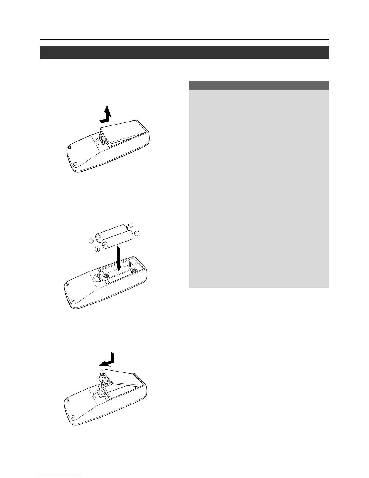
Please load batteries into the remote control. If the remote control starts to work erratically, replace the batteries.
Controls and Features
1.
Open the back cover
Push the hook on the back cover lightly in the direction of
the arrow and lift it up.
2.
Load the batteries
Place the two supplied batteries (AA/R6-size) into the remote control as illustrated below. To prevent short circuit,
be sure to insert the minus · end of the battery first.
3.
Close the back cover
Close the back cover by inserting the end first and pressing down until a click is heard.
Precautions for using batteries
If batteries are used incorrectly, they may crack or leak.
This could cause fire, burn, malfunction, staining or
damaging of the surroundings.
Beware of the following:
• Do not mix new and old batteries.
• Do not mix different types of batteries as they are different in characteristics.
• Place batteries so they match the polarities indicated on
the cartridge.
• Be sure to insert the minus
· end in first to avoid short-
circuiting.
• Do not put batteries into a fire or try to recharge them.
• Use only designated batteries.
• Remove the batteries if the remote control is not to be
used for a prolonged period.
Battery Life
Batteries run for six months to one year in normal use. However, the batteries supplied are for confirming operation and
may not run that long. When the remote control starts failing to work properly, replace the batteries with new ones.
Battery Leakage
When the batteries are totally exhausted and can no longer
be used, replace them immediately.
Leaving the batteries in the battery compartment causes
battery leakage which in turn causes malfunction.
Further, in cases where the leakage comes to contact with
the skin, wipe it away with a cloth, otherwise skin problems
may occur.
Page 15
15
Precautions for Installation
Installing the Projector
Please read the following properly when installing the projector.
Installation Environment
Please do not install or use this projector in the following places. The projector is a precision device and doing so could cause a fire or malfunction.
• Where there is water, humidity or dust.
• Where the projector may be subjected to oil, smoke or
cigarette smoke.
• On a soft surface such as a carpet or cushion.
• Where the projector may be subjected to direct sunlight.
• Where temperature is high or low.
Allowable operation temperature range : +5°C to +35°C
Allowable relative humidity range : 20% to 80%
(no condensation)
Allowable storage temperature range : –10°C to +60°C
•Any room in which there is smoke and grease.
Even where smoke and grease levels are minimal, prolonged exposure will affect the projector. The projector
emits heat and optical components are cooled down by
taking in large amount of air. The optical path being soiled
by grease/dirt can cause images to become dark and
the color projection to deteriorate. After soiling, removing grease/dirt totally from the optical parts is not possible.
Precaution for Usage
This projector uses a light-source lamp which reaches
high temperatures when projecting.
Please DO NOT use it in the following ways as doing
so may result in fire or malfunction.
• Projecting images while the projector is on its side.
• Projecting images outside the specified angle.
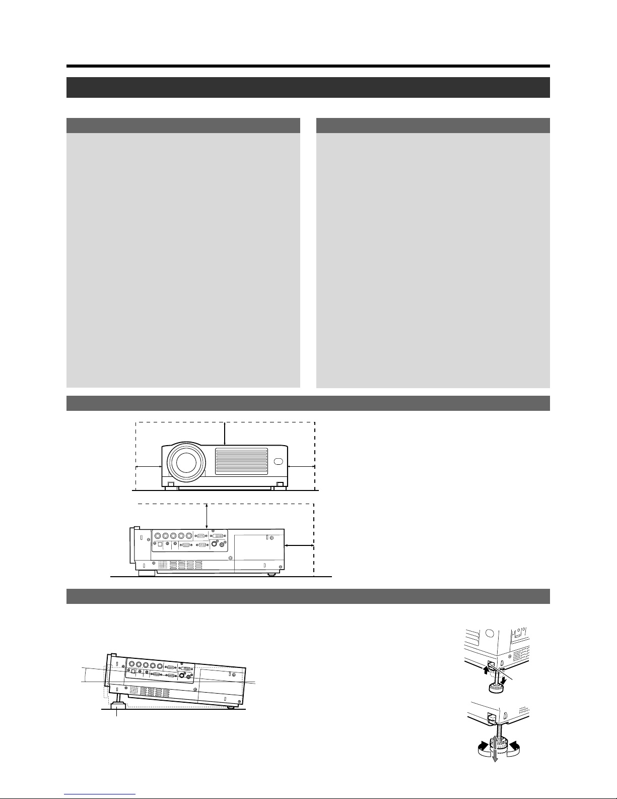
Do not use the projector while it is set more than ±5°
horizontally (left/right), or more than ±25° vertically (up/
down). This could cause color variation or shorten the
lamp life.
• Use while blocking the exhaust vents.
300mm
300mm
150mm
150mm
500mm
+6˚
Front Adjustable
Foot
Foot
Lever
Extend
Shorten
Adjusting the Inclination of the Projector
The vertical angle and leveling of the projector can be adjusted with the adjustable feet at the bottom of the projector.
Do not use a cover which may enclose the projector
air-tight or block the exhaust vents. Allow sufficient
space around the projector. When the projector is enclosed in a space of the following dimensions, use an
air conditioner so that internal and external temperatures are the same.
Adjusting the vertical angle of the projector
While pushing the lever upward, raise the projector. The maximum extension is approximately
31mm. To retract the foot, push the lever and lower
the projector slowly; the projector is fixed at the
position where you release the lever.
Adjusting the level of the projector
Lift the projector, rotate the front adjustable foot,
and adjust the horizontal angle until the projector
is level.
䡵 Vertical angle adjustment range
Minimum Space Required
Page 16
16
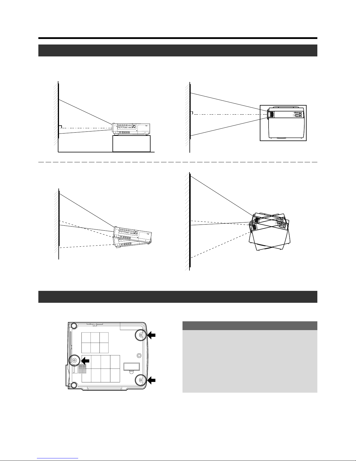
Installing the Projector against the Screen
Installing the Projector
The projector should be placed so that the center line of the lens is at a right angle to the screen as in the following figures.
䡵 Side View 䡵 Top View
● Trapezoidal-distortion can be corrected using the KEYSTONE
button on the projector. (
☞ page 30)
Up to approximately 30° upward
and downward from the horizontal line.
Up to approximately 10° upward and
downward from the vertical line.
Mounting the Projector
When mounting of the projector is required, do it using the embedded three screw holes (M6 nuts) at the bottom of the projector.
Precaution for ceiling-mount
•To ceiling-mount and adjust the projector, special expertise and techniques are necessary. Be sure to ask your
dealer or specialist to perform the work.
• Do not mount on places that will be subjected to knocks
and vibrations.
• As the depth of the screw holes is 10mm, use screws
shorter than 10mm but longer than 6mm. Otherwise, the
screws will damage the internal parts of the projector
causing malfunction.
Page 17
17
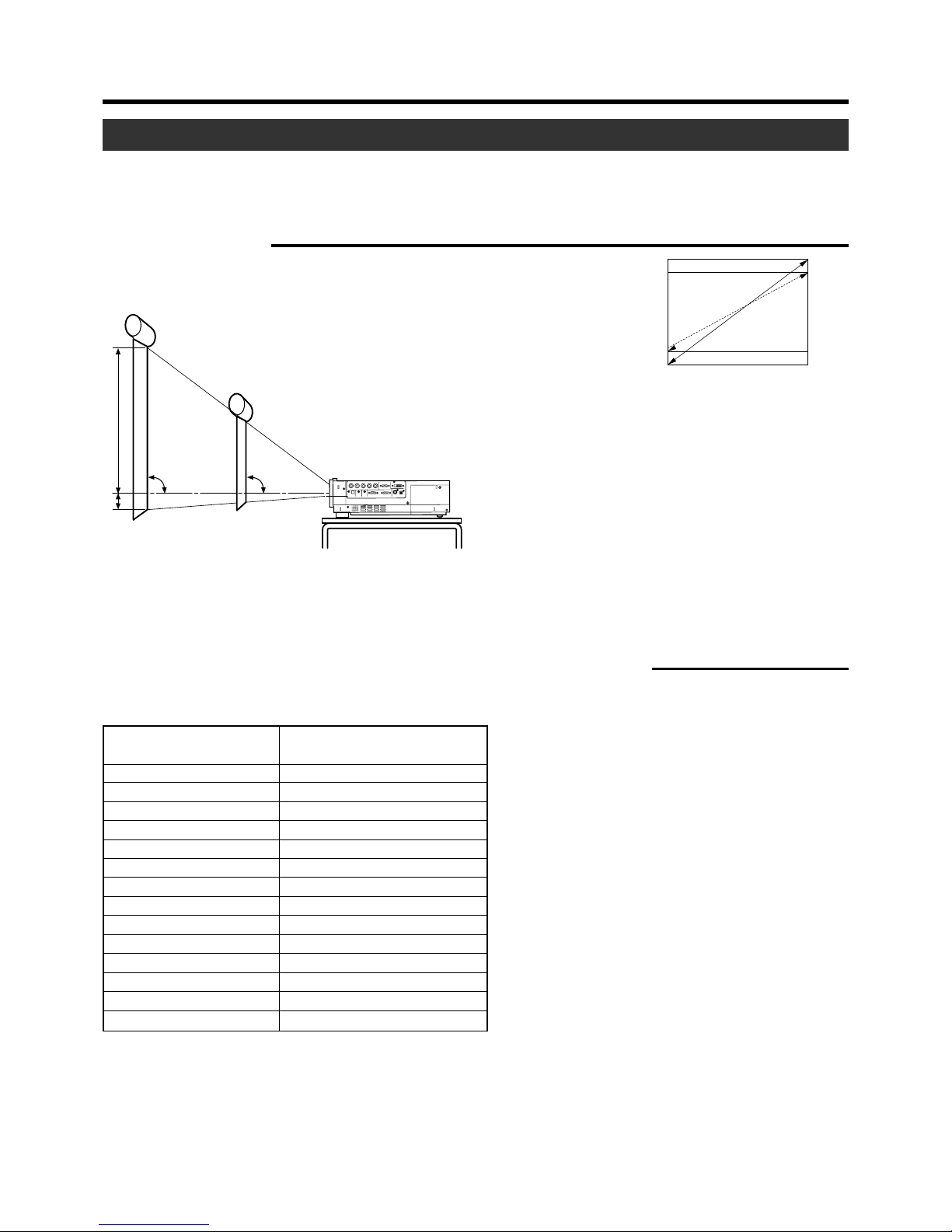
Projection Distance and Screen Size
• This projector uses 1.3x manual zoom lens for projection.
• The range of projection while retaining good focus is approximately 1.6m to approximately 12m when the aspect ratio of the
screen is 4:3. Install the projector within this range.
• If the KEYSTONE is adjusted, the screen becomes smaller. (☞ page 30)
Installing the Projector
90˚ 90˚
A:B = 9:1
A
B
Screen
4:3 and 16:9 Screen
16:9 aspect-ratio picture is projected based
on the width of the range in which a 4:3 aspect-ratio picture is projected. The diagonal
length of a 16:9 aspect-ratio screen is about
91.8% that of a 4:3 aspect-ratio screen.
䡵 Screen installation
Model 40 (approx. 106.7cm) (approx.1.56m) ~ (approx. 2.05m)
Model 60 (approx. 152.4cm) (approx. 2.37m) ~ (approx. 3.10m)
Model 80 (approx. 203.2cm) (approx. 3.18m) ~ (approx. 4.15m)
Model 100 (approx. 254.0cm) (approx. 3.99m) ~ (approx. 5.20m)
Model 120 (approx. 304.8cm) (approx. 4.80m) ~ (approx. 6.25m)
Model 140 (approx. 355.6cm) (approx. 5.61m) ~ (approx. 7.31m)
Model 160 (approx. 406.4cm) (approx. 6.42m) ~ (approx. 8.36m)
Model 180 (approx. 457.2cm) (approx. 7.22m) ~ (approx. 9.41m)
Model 200 (approx. 508.0cm) (approx. 8.03m) ~ (approx. 10.46m)
Model 220 (approx. 558.8cm) (approx. 8.84m) ~ (approx. 11.51m)
Model 240 (approx. 609.6cm) (approx. 9.65m) ~ —
Model 260 (approx. 660.4cm) (approx. 10.46m) ~ —
Model 280 (approx. 711.2cm) (approx. 11.27m) ~ —
Model 300 (approx. 762.0cm) (approx. 12.08m) ~ —
䡵 Relationship between projection distance and projection screen size
Projection screen size of 4:3
aspect Ratio (Diagonal length)
Approximate projecting distance
W(Wide) ~ T(Tele-)
* The projection screen sizes and projecting distances in the table above are provided only as a guide (reference). Please use them
during installation. The projected image size may vary depending on the manufacturing tolerance of the projection lens. Please
use the ‘Wide’ side for sizes bigger than Model 220. The guaranteed projection distance range is from 2m to 10m.
Page 18
18
Q
U
I
C
K
A
L
I
G
N
.
P
C
V
I
D
E
O
V
O
L
U
M
E
P
R
E
S
E
T
H
I
D
E
M
E
N
U
E
X
I
T
F
R
E
E
Z
E
O
P
E
R
A
T
E
V
-K
EYS
TON
E
H-K
EYSTONE
S
C
R
E
E
N
D
I
G
I
T
A
L
Z
O
O
M
FOCUS
W
S
E
N
T
E
R
Screen
Projector
Projector
Remote Control
Unit
Remote Control Sensor
(rear)
20˚
20˚
30˚
A
B
30˚
QUI
CK A
LIGN.
P
C
V
IDEO
V
O
L
U
M
E
PRESE
T
HIDE
MENU
EXIT
FREEZE
O
P
E
R
A
T
E
V
K
E
Y
S
T
O
N
E
H
K
E
Y
S
T
O
N
E
S
C
R
E
E
N
D
I
G
I
T
A
L
Z
O
O
M
FOCUS
W
S
E
N
T
E
R
30˚
20˚
20˚
30˚
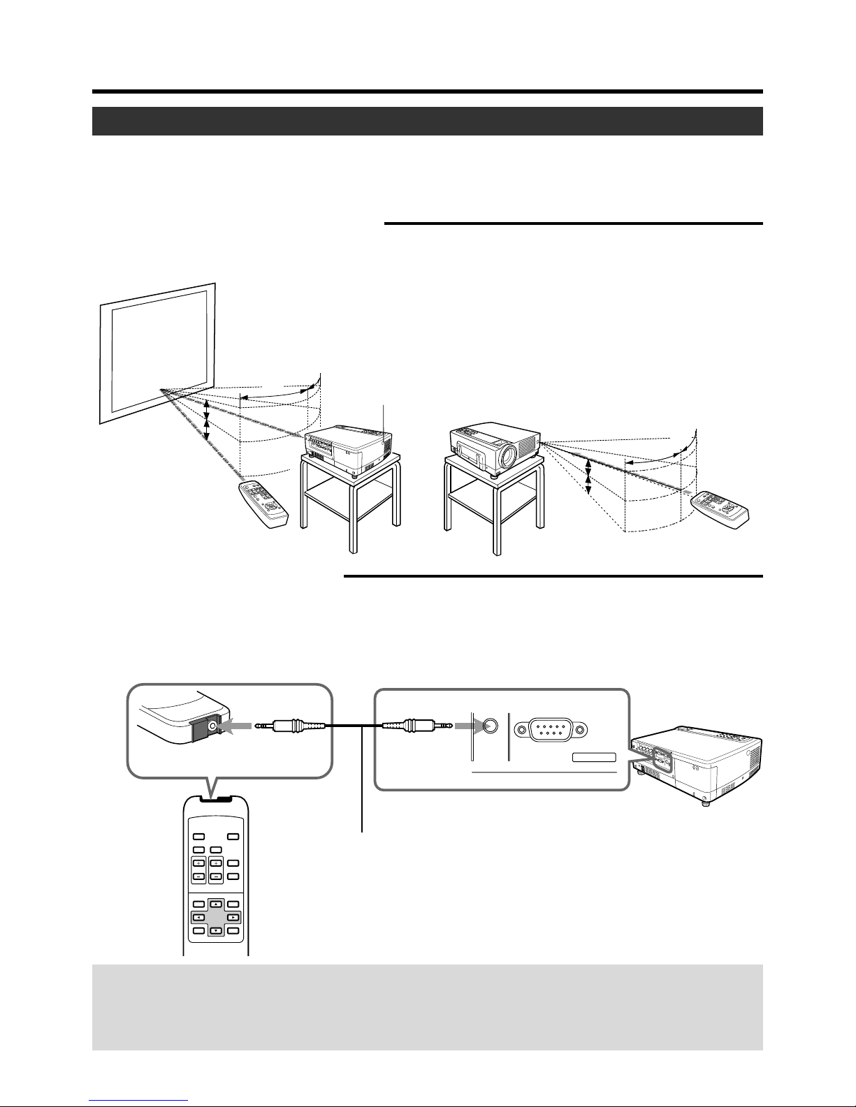
Aim the remote control unit towards the remote sensor on the front or rear of the projector. The operable
distance of the remote control unit is about 7m for direct reception. If the remote control fails to work properly, move closer to the projector.
Remote Control
Unit
QUICK
ALIGN.
PC VIDEO
DIGITAL
ZOOM
HIDE
VOLUME
PRESET
ESCAPE ENTER
MENU
FREEZE
OPERATE
REMOTE
RS-232C OUT
CONTROL
Remote Cable
(sold separately)
Remote control
(sold separately)
Projector
Again, when a remote cable is connected to the REMOTE terminal of the
projector, the sensor does not work. Check to see if the cable is connected.
When a remote cable is connected to the remote control terminal, the
transmitter does not work.
Effective Range and Distance of the Remote Control Unit
When the remote control unit fails to work properly
• When the batteries in the remote control unit are exhausted, improper functioning will occur. Please replace with new
batteries.
• When either the remote control unit or projector alone is connected to the remote cable, the item connected will not be able
to work. Please check the cable connection.
The operable distance of the remote control unit is about 7m for direct reception. The remote control unit can be used by having the
transmission signal reflected off a screen. In this case, please set the total distance A + B where A is the distance from
projector to screen and B is the distance from screen to remote control, within 7m. The operable angles of the remote control
unit are 30˚ right and left, and 20˚ up and down.
䡵 Using as a wireless remote control unit
As the effect of signals reflected from the remote control unit differ with the type of screen used, effective range and distance
may decrease.
䡵 Using as a wired Remote Control
By connecting a separately sold remote control (RM-M3010) and cable (about 3m: QAM0081-001/ about 15m: QAM0247-001)
to the REMOTE terminal, the remote control can be used as a wired control unit. When connected to the cable, the remote
control’s transmitter and the projector’s sensor do not function. Please keep within the range of the remote cable length. Warranty is not extended to the case where an extension cord is used.
❈ The ESCAPE button on the separately sold remote control (RM-M3010) is equivalent to the EXIT button on the supplied
remote control unit. There is no equivalent to the H, V-KEYSTONE and FOCUS buttons found on the supplied remote control.
Installing the Projector
Page 19
19
Signals that can be input into the projector
The following signals can be input to the projector.
Connecting to Various Devices
Video signals
(1) Response to Decoder
NTSC NTSC4.43 PAL SECAM
VIDEO O O O O
Y/C O O*
1
O –––––
Y, P B/CB,PR/CR*
3
O*
2
O*
2
O*
2
O*
2
G,B,R,H/Cs,V*
4
O*
2
O*
2
O*
2
O*
2
*1: Responds if Y/C output is available.
*2: Signifies that component signals (Y, PB, PR/Y, B-Y, R-Y/G, B, R, H/Cs, V) conform to the signal timing (synchronization and video
period ) of each decoder. The decoders are used for convenience.
*
3
:To use these signals, it is required to set the “PC2 (BNC)” item in the “Options” menu to “YPBPR”. (☞ page 39)
*4:To use these signals, it is required to set the “PC2 (BNC)” item in the “Options” menu to “RGB”. (☞ page 39)
(2) Responds to double density(*5), high-vision signals.
NTSC*
6
PAL*
7
High-vision signal
Y, P B/CB,PR/CR*
8
OOO
G,B,R,H/Cs,V*
9
OOO
*5: Signals of which density of scanning lines per field is twice as high.
*
6
: Responds to signals of which the horizontal scanning frequency is 33.25kHz. NTSC can be made twice as dense by a line
doubler (separately available: recommended article). It can also respond to fully-specified, decoded wide-clear-vision signals
and decoded 525p progressive signals.
*
7
: Responds to signals of which the horizontal scanning frequency is 33.5kHz. PAL can be made twice as dense by a line doubler
(separately available: recommended article).
*8:To use these signals, it is required to set the “PC2(BNC)” item in the “Options” menu to “YPBPR”.(☞ page 39)
*
9
:To use these signals, it is required to set the “PC2(BNC)” item in the “Options” menu to “RGB”.(☞ page 39)
(3) Response to DTV-format signals
DTV-format signals (480i, 480p, 720p, 1080i) can be input to the Y, PB/CB, PR/CR*10 input terminals.
*
10
: To use these signals, it is required to set the “PC2(BNC)” item in the menu “Option” to “YPBPR”.(☞ page 39)
Computer signals
● Computer signals can be input to the PC1, PC2 (G,B,R,H/Cs,V) or PC3 (DVI-D) terminals.
Scanning frequencies in the following ranges can be inputted.
Horizontal scanning frequency : 15kHz ~ 120kHz
Ver tical scanning frequency : 50Hz ~ 120Hz
Be sure that the computer used meets the following conditions.
• The computer has a video signal output port.
Confirm if the computer has a video signal output port by consulting the computer’s manual.
The video signal output port is generally called ‘RGB port’, ‘monitor port’, or ‘video port’.
In the case where the computer comes with a built-in monitor, eg; a notebook, an external output port may need to be
purchased. Also, note that an external output port cannot be installed in some computers.
• The resolution and the scanning frequencies are within the range specified in the table on page 20.
Be sure that the resolution and the scanning frequencies of the video signal are within this range.
Video signals out of this range should not be used.
(Out of range signals can be projected but the image may not turn out sharp. Signals within the range may occasionally
require adjustment, depending on the video board used). When signals other than those listed in the table on page 19 are
input, the image could be partially erased or unwanted folds-over the image could appear.
Some signals within the frequency range may not be displayed normally depending on the type of the signal.
Composite sync (Cs) and G on Sync signals cannot be handled depending on the devices connected.
Input terminal
Decoder
Input terminal
Decoder
Page 20
20
PC98 VESA350
PC/AT PC98
DOS/V VGA 60Hz*
DVI* VGA 72Hz*
VGA 75Hz*
VGA 85Hz*
SVGA 56Hz*
SVGA 60Hz*
SVGA 72Hz*
SVGA 75Hz*
SVGA 85Hz*
XGA 43Hz*
XGA 60Hz*
XGA 70Hz*
XGA 75Hz*
XGA 85Hz*
SXGA 43Hz*
SXGA 60Hz*
SXGA 75Hz*
SXGA 85Hz
SXGA+
UXGA 60Hz
Mac MAC13
MAC16
MAC19
MAC21
Video HDTV(1035i) 60Hz
HDTV(1035i) 59Hz
480p
720p 60Hz
720p 59Hz
1080i 60Hz
1080i 59Hz
1080i 50Hz
1080 30SF/30P
1080 25SF/25P
1080 24SF/24P
NTSC
PA L
SECAM
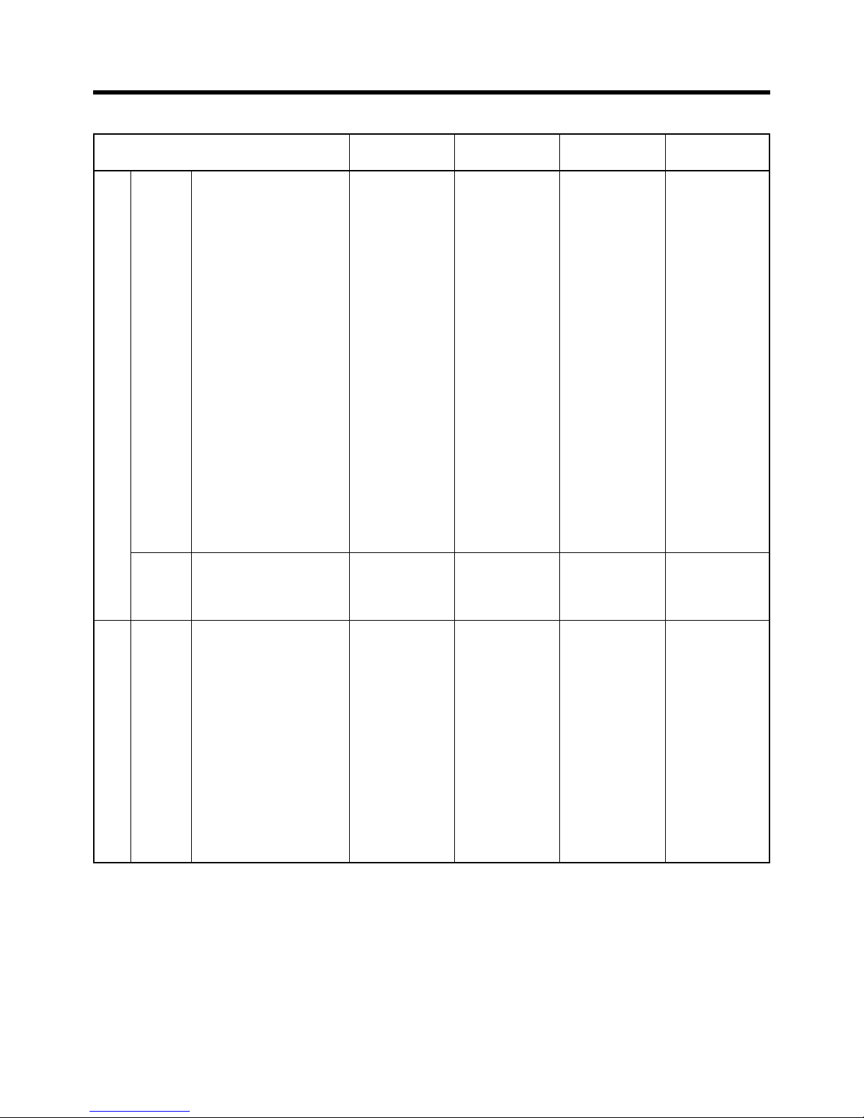
Connecting to Various Devices
Allowable input signals
Signal
Horizontal resolution Vertical resolution Horizontal frequency Vertical frequency
Hor[Pixels] Ver [Lines] H [kHz] V [Hz]
PC system
640
640
640
640
640
640
800
800
800
800
800
1024
1024
1024
1024
1024
1280
1280
1280
1280
1400
1600
640
832
1024
1152
720
1280
1280
1920
1920
1920
1920
1920
1920
350
400
480
480
480
480
600
600
600
600
600
768/2
768
768
768
768
1024/2
1024
1024
1024
1050
1200
480
624
768
870
483
720
720
1080/2
1080/2
1080/2
1080
1080
1080
37.86
24.83
31.47
37.86
37.50
43.27
35.16
37.88
48.08
46.88
53.67
35.52
48.36
56.48
60.02
68.68
46.43
63.98
79.98
91.15
64.02
75.00
35.00
49.73
60.24
68.68
33.75
33.72
31.47
45.00
44.96
33.75
33.72
28.125
33.750
28.125
27.000
15.734
15.625
15.625
84.13
56.42
59.94
72.81
75.00
85.01
56.25
60.32
72.19
75.00
85.06
43.48
60.00
70.07
75.03
85.00
43.44
60.02
75.03
85.02
60.00
60.00
66.67
74.55
74.93
75.06
60.00
59.94
59.94
60.00
59.94
60.00
59.94
50
60/30
50/25
48/24
60
50
50
VIDEO system
• UXGA signals cannot be projected when the screen mode is set to 16:9. (☞ page 31)
• The resolutions for the input signals are listed in the table above.
• Certain types of signals in the frequency range may not be displayed normally.
• When a signal other than those listed above is input, the image could be partially erased or unwanted folds-over the image may
appear.
• Some signals other than those listed above can be displayed. However, they may require adjustment.
• Some of the signals listed above may require adjustment depending on the video board used.
• Composite sync (Cs) and G on Sync signals cannot sometimes be handled depending on the devices connected.
•VGA signals from the PC could at times be displayed in the video 480p mode.
(In this case, the projector enters the video menu when the MENU button is pressed.)
Page 21
21
R
PR/C
R
GYB
PB/C
S
VDVIH/C
S
PC1
PC3
PC2
AUDIO IN
REMOTE
DC OUT
5V }1.5A
RS-232C OUT RS-232C IN Y/C VIDEO
CONTROL VIDEO IN
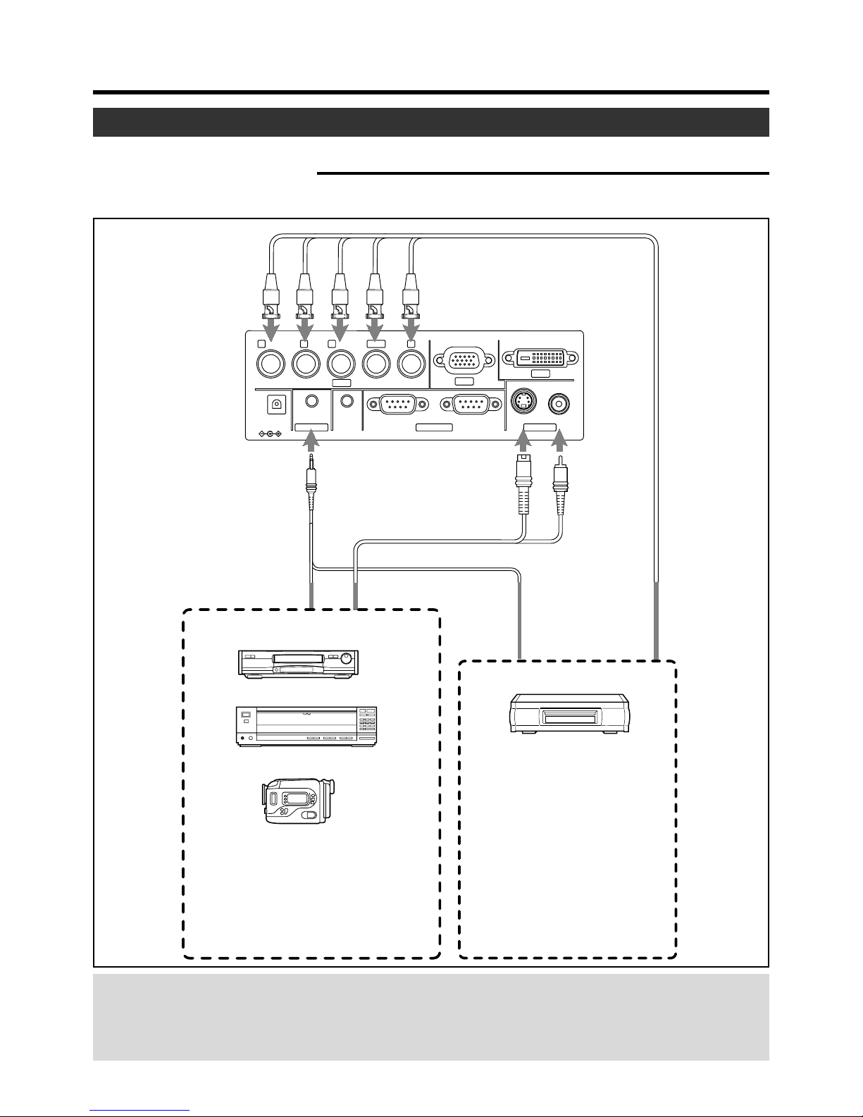
Video Device 1
Video Device 2
VCR (Video cassette recorder)
S-video cable
(separately available)
PC Audio cable
(separately available)
AV connection
cable (separately
available)
BNC Cable (separately available)
W-VHS or DVD player etc.
Laser videodisc player
Camcorder
Right side of projector
Image input
• Connect a composite image signal output
device or Y/C (S-video) image output device.
Sound input
• Connect to AUDIO IN terminal.
Image input
• Connect to component signal output device, DTV format signal output device, etc.
• When the PC2 input terminal is
used, the “PC2(BNC)” item in
“Options” menu must be correctly
set. (☞ page 39)
Sound input
• Connect to AUDIO IN terminal.
Connecting to Various Devices
Before connection, be sure to turn off both the projector and the device.
Connecting to Video Devices
• Thoroughly read the manual that comes with each video device.
• Use the supplied AV connection cable. S-video [Y/C] cable, BNC cable and PC Audio cables are not supplied.
Connection
• When connecting a video device, please use a TBC along with it, or use one with a built-in TBC.
• Use of an extension cable to connect a video device and the projector could cause image deterioration or projection failure.
• When a signal with much jitter is reproduced on a VCR, or special-effect playbacks are performed, the upper part of the
image or the screen may be interrupted, erased or distorted.
Connecting to Devices
Page 22
22
R
PR/C
R
GYB
PB/C
S
VDVIH/C
S
PC1
PC3
PC2
AUDIO IN
REMOTE
DC OUT
5V }1.5A
RS-232C OUT RS-232C IN Y/C VIDEO
CONTROL VIDEO IN
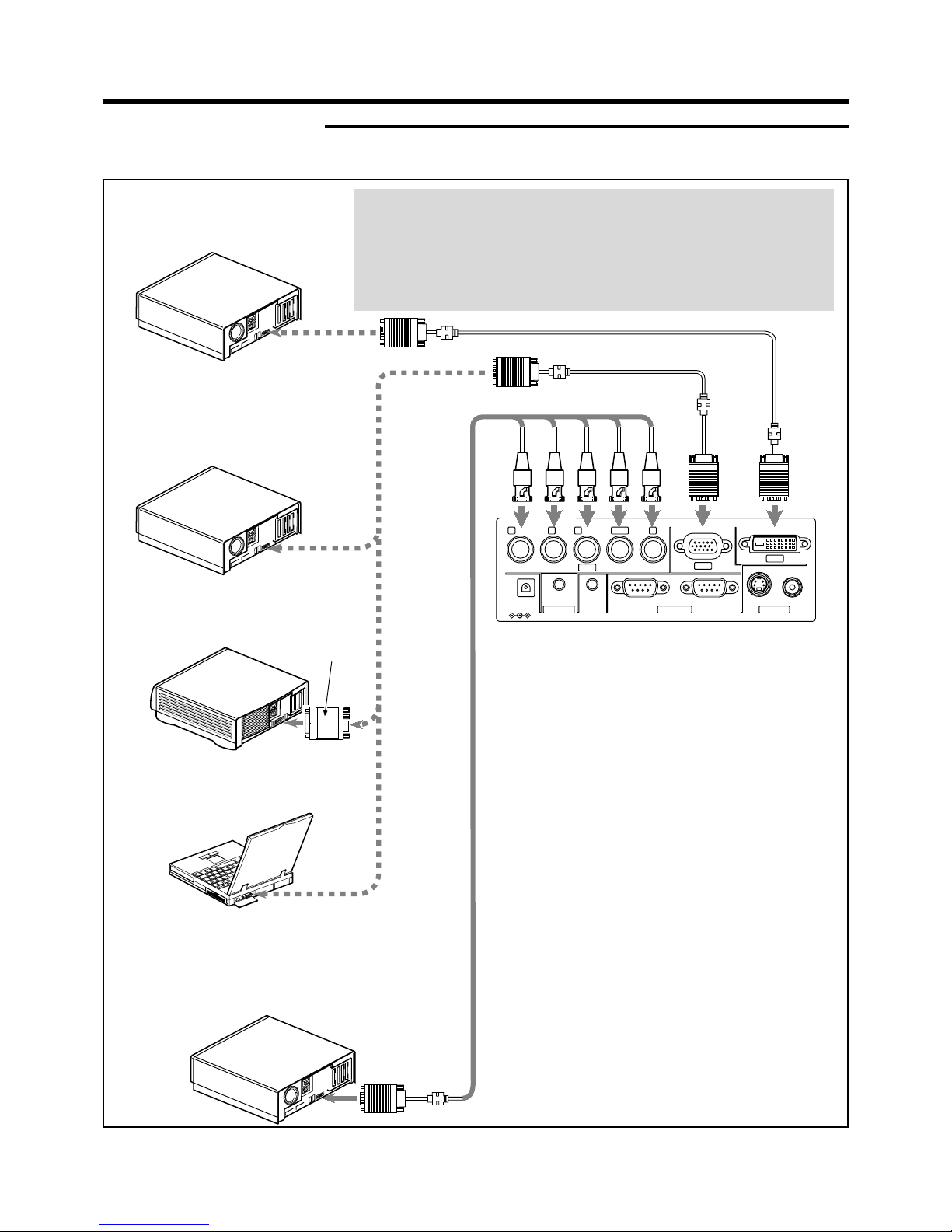
To monitor
connector
Personal Computer connector cable (supplied)
Right side of projector
Desktop type (DOS/V, PC-9800 etc.)
Desktop type (DOS/V, etc.)
Desktop type
(Macintosh)
Notebook Type
Desktop type
To PC1 To DVI
To PC2
To monitor
connector
Conversion
adapter for MAC
(separately available)
To monitor
connector
Separated cable
(separately available)
❈There are some notebook type computers that do
not allow the computer’ s LCD to work if an external
display device is connected. With such computers,
the LCD display and external display output need to
be switched.
Connecting to Various Devices
Connecting to Computers
• Thoroughly read the manuals that come with the computer used.
• Use the supplied computer connection cable. Also prepare cables for connecting the devices.
• When the PC2 input terminal is used, “PC2 (BNC)” must be selected from the
“Options” menu. (☞ page 39)
• When connecting an audio output terminal such as a computer sound source to
the projector, connect to the AUDIO terminal using the separately available audio
cable.
• When connecting to PC-9800 Series computers, a separately available conversion adapter is necessary. Please confirm the monitor connector type before use.
Page 23
23
Notebook type
Connect to Computer
Connect to the IN
terminal of third projector
RS-232C connection cable
(separately available)
(Cross cable)
Projector
Second projector
R
PR/C
R
GYB
PB/C
S
VH/C
S
PC1
PC2
AUDIO IN
REMOTE
DC OUT
5V }1.5A
RS-232C OUT RS-232C IN
CONTROL
B
PB/C
S
VH/C
S
PC1
PC2
REMOTE
RS-232C OUT RS-232C IN
CONTROL
B
PB/C
S
VH/C
S
PC1
PC2
N
REMOTE
RS-232C OUT RS-232C IN
CONTROL
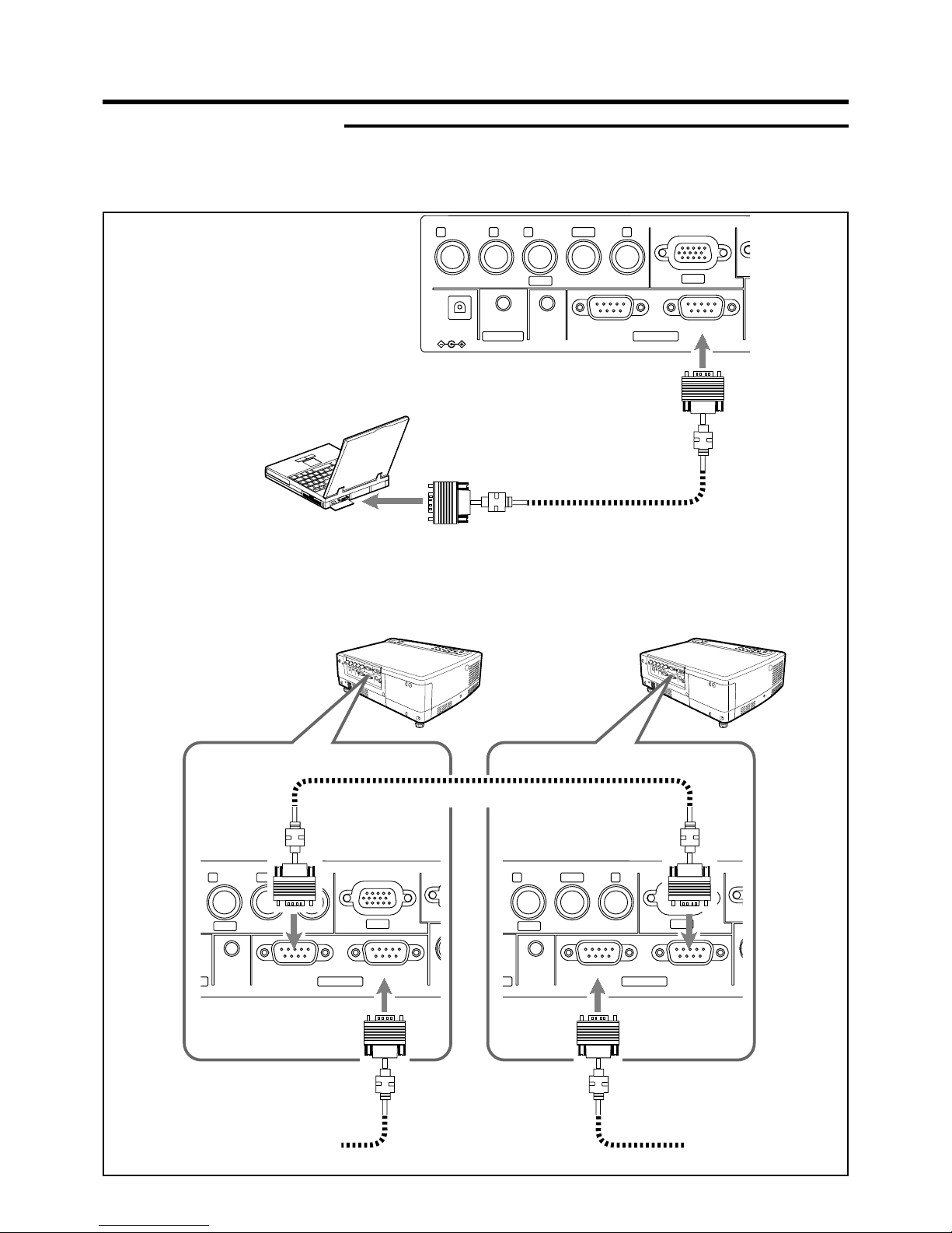
RS-232C connection cable (separately available)
(Cross cable)
Connection for controlling more than one projector
By using the CONTROL terminal, more than one projector can be controlled simultaneously by one computer.
Connect these projectors in series by connecting the OUT terminal of the first projector to the IN terminal of the second
projector, then the OUT terminal of the second projector to the IN terminal of the third projector, etc.
Connecting to Various Devices
Control from external device
• It is possible to control the projector with a computer by connecting the computer to the CONTROL RS232C IN terminal of the
projector.
❈ Please request a connection cable from us if needed.
❈ For more information, please contact your authorized dealer.
Page 24
24
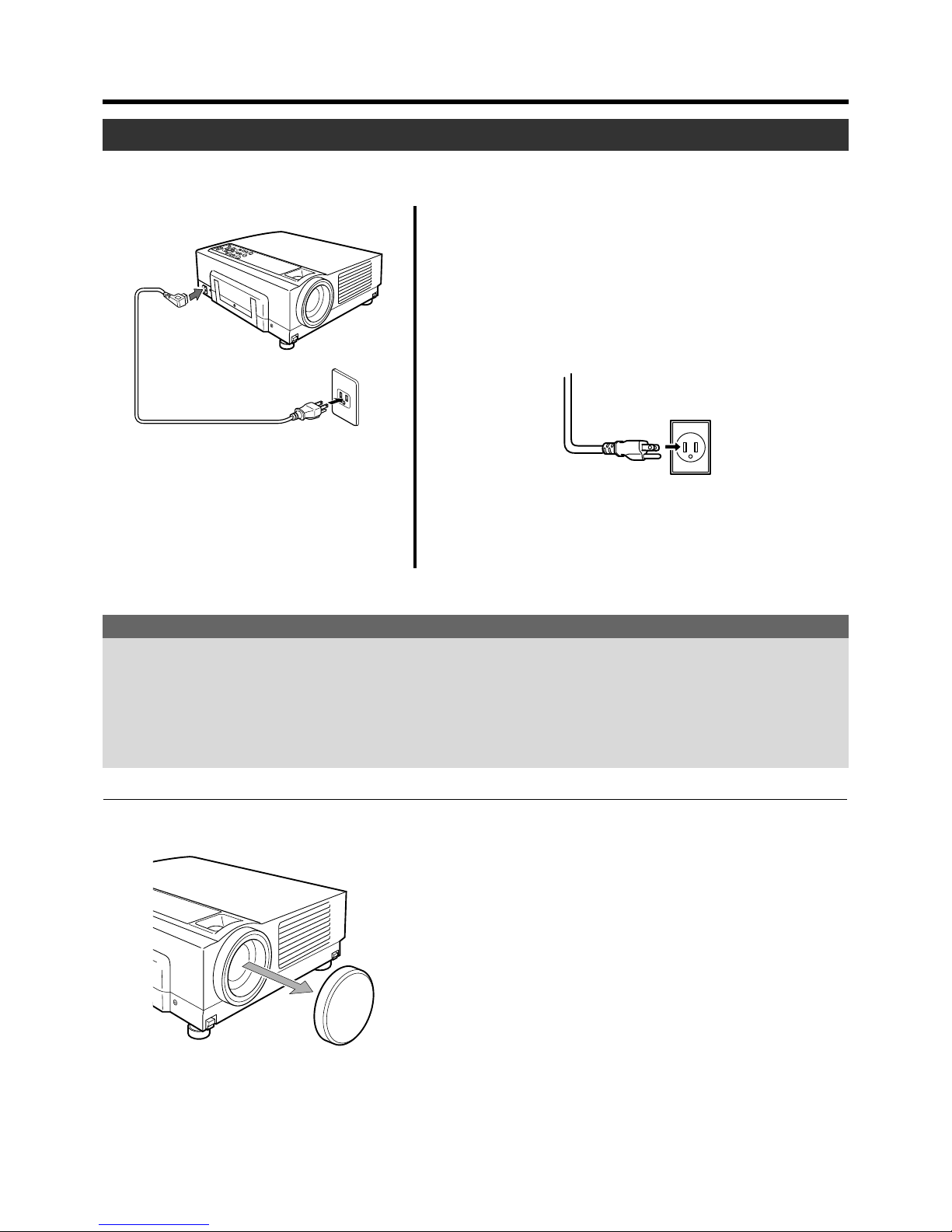
Power cord (supplied)
2
1
Connecting to Various Devices
1.
Connect the supplied power cord to the power input terminal of the projector.
2.
Insert the main plug of the supplied power cord into the
wall outlet.
After all devices have been connected, connect the supplied power cord.
Connecting the Power Cord (supplied)
Lens Cap
Cautions Against Fire and Electric Shock
● Since the power requirement of the projector is high, please insert the power plug directly into a wall outlet.
● When not using devices, remove the power cords from the wall outlets.
● Do not use power cords other than those supplied.
● Do not use a power voltage different from that which is indicated.
● Do not cut, tear or modify the power cords. Also, do not put a heavy object on, heat, or stretch the power cords, otherwise they
may be damaged.
● Do not insert or pull out the plugs with a wet hand.
When using the projector:
● Remove the lens cap.
❈ Be sure to fit the lens cap on when the projector is not in use to
keep out dirt.
❈ Please do not project with the lens cap on. The Lens cap may be
deformed by heat.
Removing the Lens Cap
(eg.)
Page 25
25
MENU
V-KEYSTONE
PC
LAMP
H-KEYSTONE VOL.
EXIT
ENTER
VIDEO
TEMP
STAND BY
OPERATE
1-
2
2
QUICK ALIGN.
PC VIDEO
VOLUME
PRESET HIDE
ENTER
MENU EXIT
FREEZE
OPERATE
V-KEYSTONE H-KEYSTONE
SCREEN
DIGITAL
ZOOM
FOCUS
W
S
1-
2
2
LAMP TEMP
STAND BY
OPERATE
Light on
Projector: Indicator part
LAMP TEMP
STAND BY
OPERATE
Light on
OPERATE
OPERATE
Projector:
Control panel
Remote control
unit
Projector : Indicator
Basic Operations
Note
• Messages are displayed in the language set
by the user in the “Language” menu. The preset language upon purchase is “English”. The
user can choose from 8 national languages.
(☞ page 39)
However, the input mode (PC 1, PC 2, PC 3,
Y/C, VIDEO) and button indications (FREEZE,
D.ZOOM, EXIT) are only displayed in English
irrespective of the display language setting.
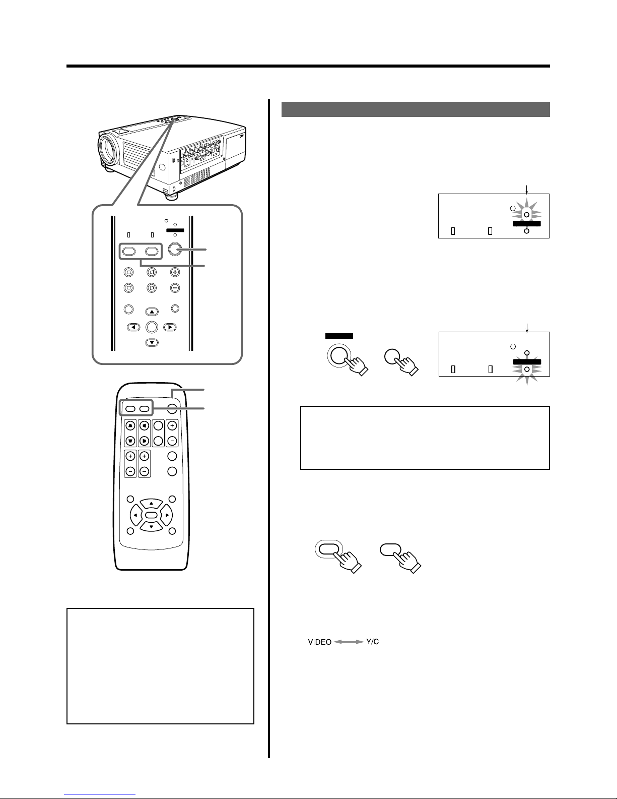
Basic Operation Procedures
Once the basic settings are done, follow the procedures below:
1.
Power On
1 The STAND BY indicator lights up when the power cord is
connected.
2 Press the OPERATE button on the projector (or the OPER-
ATE button on the remote control unit) for one second or
more.
The OPERATE indicator lights up and the projected image slowly
appears.
2.
Selecting the image to be projected
Press VIDEO to select which of the image devices (of those
connected to the VIDEO IN (VIDEO or Y/C) terminals) is output.
Each time you press either button, the selected input changes as
follows.
Notes
• Upon projection, the image may flicker for a few seconds, but
this is not a malfunction.
• When the lamp is turned on, it will slowly become brighter. It
will take more than a minute for the brightness to stabilize.
VIDEO : Image from the input VIDEO ter-
minal on the right hand side of projector will be projected.
Y/C : Image from the input Y/C terminal
on the right hand side of the projector will be projected.
If projector set up is not yet complete, please read ‘Adjustments and Settings Using Menus’ on page 32 and perform the necessary
settings.
VIDEO
VIDEO
Projector:
Control panel
Remote Control
Unit
Page 26
26
PC 1
PC 2
PC 3
Y/C
VIDEO
Audio-Vol 12
Digital Zoom x12
Vert.Keystone
0
Horiz.Keystone
0
3.
4.
Tele side
Wide side
Near side
Far side
Basic Operations
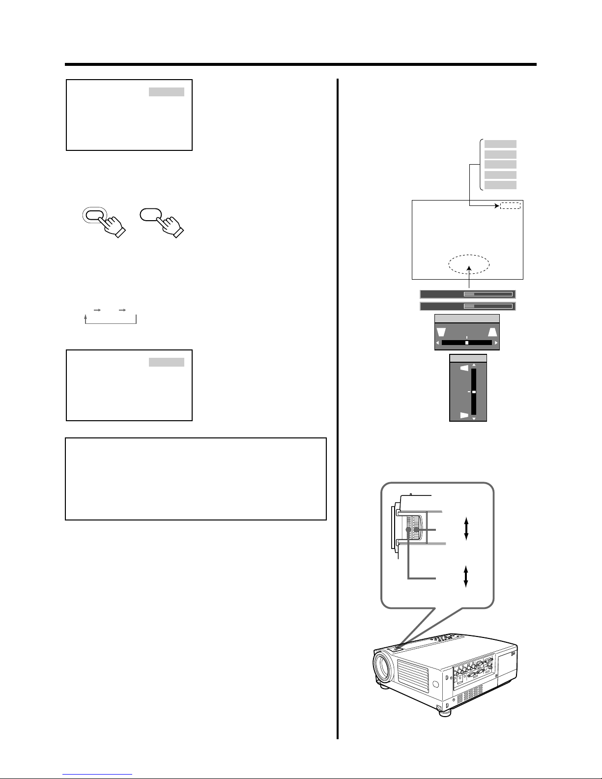
Display using the direct buttons
The direct buttons enable direct switching and
operation without having to go through the
menu.
Input mode can be selected by
pressing the PC button or the
VIDEO button.
When the DIGITAL ZOOM, VOLUME, V-KEYSTONE
or H-KEYSTONE buttons are pressed, the level bar
of the function is displayed.
VIDEO
Screen display
PC
PC
Projector:
Control Panel
Remote Control
Unit
PC1 PC2 PC3
PC1
Screen display
When “Line display” (☞ page 39)
is set to “5 sec” : After changing an
input , the new selection will appear on the screen for about 5 seconds.
To select a computer or other devices connected to PC1,
PC2 or PC3 : Press PC
Upon pressing the button, the input mode changes as follows.
PC1 : Projects image from PC1 input terminal
on the right hand side of the projector.
PC2 : Projects image from PC2 input terminal
on the right hand side of the projector
PC3 : Projects image from PC3 input terminal
on the right hand side of the projector.
When “Line display” (☞ page 39)
is set to “5 sec”: after changing an
input, the new selection will appear
on the screen for about 5 seconds.
Notes
• Sound is formed from sound signals connected to the AUDIO terminal.
• When no image is input to the selected input terminal, the message “No Input” is displayed on the screen. (☞ page 49)
• When the PC2 input terminal is used, “PC2(BNC)” must be selected from the “Options” item in the main menu. (☞ page 39)
3.
Adjusting the Zoom Ring (the screen size) for DLA-
To enlarge the screen size: Turn the zoom ring towards the ‘Wide’
side.
To reduce the screen size: Turn the zoom ring towards ‘Tele’ side.
4.
Adjusting the Focus Ring (Focus)
To f ocus on nearer points: Turn the focus ring towards the ‘Near’
side.
To focus on farther points: Turn the focus ring towards the ‘Far’
side.
Page 27
27
MENU
V-KEYSTONE
PC
LAMP
H-KEYSTONE VOL.
EXIT
ENTER
VIDEO
TEMP
STAND BY
OPERATE
5
OPERATE
OPERATE
QUICK ALIGN.
PC VIDEO
VOLUME
PRESET HIDE
ENTER
MENU EXIT
FREEZE
OPERATE
V-KEYSTONE H-KEYSTONE
SCREEN
DIGITAL
ZOOM
FOCUS
W
S
5
VOL.
VOLUME
Projector:
Control panel
Remote Control
Unit
LAMP TEMP
STAND BY
OPERATE
Tu r n onTu r n off
OPERATE
OPERATE
Projector:
Control Panel
Remote Control
Unit
Projector: Indicator part
Basic Operations
5.
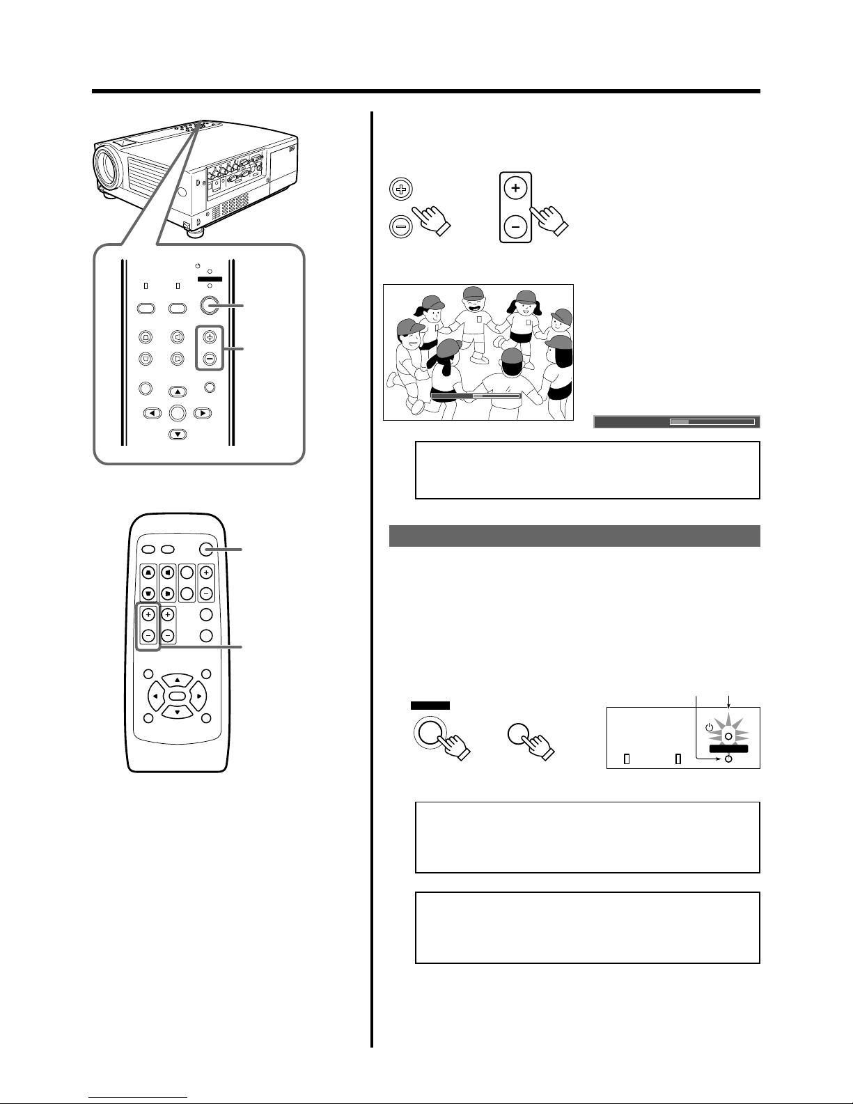
Adjusting the Sound Volume
To increase the volume: press VOLUME ª (0 ➞ 50)
To lower the volume : press VOLUME
· (50 ➞ 0)
When “Menu display” (☞ page 39) is
set to “15sec”, after pressing the VOLUME button, the sound volume display
will appear on the screen for about 15
seconds.
(Press EXIT button to immediately remove the Audio-vol display.)
Note
• When the sound volume is displayed on the screen, pressing
the PRESET button will reset the set value to “0”.
Power Off
1.
Press the OPERATE button on the projector (or the OPERATE button on the remote control unit ) for 1 second
or more.
The OPERATE indicator will disappear, the STAND BY indicator
starts to blink, and the projector goes into the cool-down mode.
● The STAND BY indicator will continue blinking for approximately
90 seconds as the temperature of the light source lamp cools (Cool
Down Mode).
Note
• The OPERATE button will not work for approximately 1 minute
from when the light-source lamp is turned on. Wait approximately 1 minute before pressing.
Caution
• Please do not pull out the plug from the power source when
the STAND BY indicator is blinking. It will shorten the life of
the lamp and cause a malfunction.
Screen display
Audio-Vol
Audio-Vol 12
Page 28
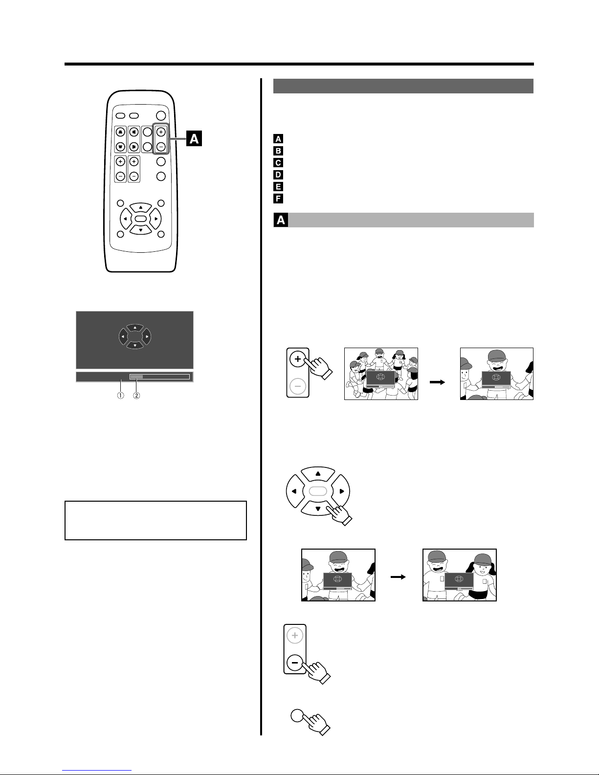
28
QUICK ALIGN.
PC VIDEO
VOLUME
PRESET HIDE
ENTER
MENU EXIT
FREEZE
OPERATE
V-KEYSTONE H-KEYSTONE
SCREEN
DIGITAL
ZOOM
FOCUS
W
S
Digital zoom X1.2
Direction buttons available
DIGITAL
ZOOM
Remote Control
Unit
x 2.0
Digital zoom X1.2
Direction buttons available
Digital zoom X2
Direction buttons available
ENTER
Remote Control Unit
Digital zoom X1.2
Direction buttons available
Digital zoom X2
Direction buttons available
DIGITAL
ZOOM
PRESET
Frequently used Convenient Functions
When an image is projected onto the screen, the following operations
can be performed directly without going through the menu operation.
(☞ page 27 for VOLUME operation.)
DIGITAL ZOOM
HIDE
FREEZE
KEYSTONE
QUICK ALIGN. (quick alignment)
SCREEN
Basic Operations
Note
• The quality of the zoomed image is reduced
in comparison with the original.
“Digital zoom” Display
1 Magnifying power display
x1.0: 1 time (standard) x2.0: 2 times
x1.2: 1.2 times x2.5: 2.5 times
x1.4: 1.4 times x3.2: 3.2 times
x1.6: 1.6 times x4.0: 4 times
2 Level Display
Level shown is based on selected magnification.
Enlarging the Image
We can zoom in while not changing the size of the projected image. After
zooming, the position of the image displayed can be moved.
● This cannot be done using the projector buttons. Please use the re-
mote control unit.
1.
Press DIGITAL ZOOM ª.
The “Digital zoom” display appears on the screen and the projector
changes to the Digital Zoom Mode.
• The image on the screen can be enlarged in 8 stages by pressing
this button. (including the standard size)
To reduce the size of the image
When the DIGITAL ZOOM · button is pressed, the
previously enlarged image will be reduced progressively until it returns to the original size.
To reduce the image to the original size
When the PRESET button is pressed, the image will
return to its original size and position.
(Please operate while “Digital zoom” is displayed.)
2.
While “Digital zoom” display appears on the screen, you
can move the zoomed image with the cursor buttons on
the remote control.
To see the upper part of zoomed image:
Press .
To see the lower part of zoomed image:
Press
.
To see the right part of zoomed image:
Press .
To see the left part of zoomed image:
Press
.
Page 29
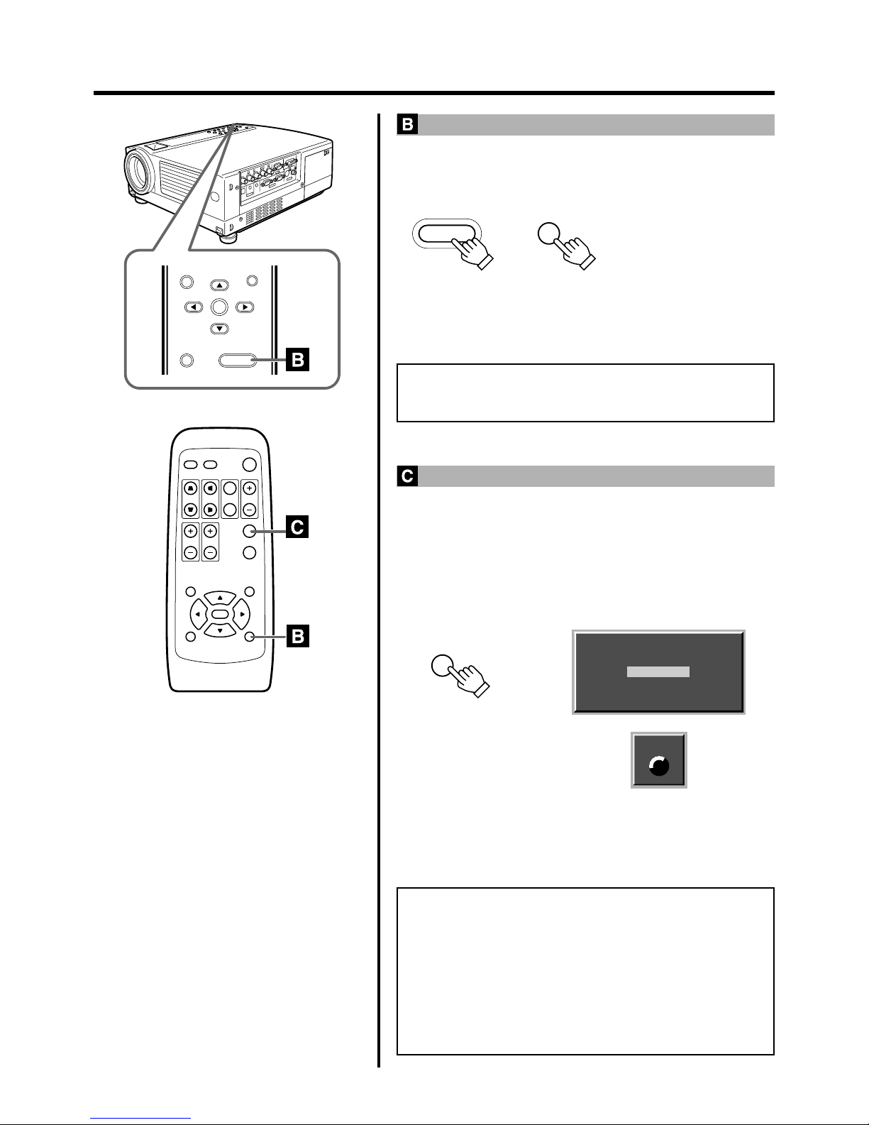
29
PRESET
MENU
EXIT
ENTER
HIDE
QUICK ALIGN.
PC VIDEO
VOLUME
PRESET HIDE
ENTER
MENU EXIT
FREEZE
OPERATE
V-KEYSTONE H-KEYSTONE
SCREEN
DIGITAL
ZOOM
FOCUS
W
S
HIDE
HIDE
Projector:
Control Panel
Remote Control
Unit
Digital zoom available
Frozen
FREEZE
“FREEZE” icon
FREEZE
Remote Control Unit
Basic Operations
Turning Off Image and Sound
Video images and audio output can be turned off temporarily.
Press the HIDE button once.
Images and audio output turned off.
Press the HIDE button again.
Images and audio output turn on again.
Note
• When the projected image input is changed, the HIDE function is
cancelled and image and sound return.
Displaying a Still Picture
The projected image can be paused temporarily.
• This operation cannot be operated by the projector buttons. Please use
the remote control unit.
Press the FREEZE button.
The image pauses after the FREEZE button is pressed for a few seconds
and a message is shown in the center of the screen. An icon indicating
“FREEZE” mode will be displayed on the top right corner of the screen.
To de-freeze the image
When you press the FREEZE button again, the image de-freezes and
resumes.
Notes
• After de-freezing a still image, note that the projector will not play
the image that comes immediately after. (Should you want to play
the image that comes immediately after that at which the freeze
button was pressed, please pause the image using the controls at
the input device.)
• MENU, QUICK ALIGN, H and V KEYSTONE and SCREEN buttons do not function when the image is still.
• The “FREEZE” message will disappear after 5 seconds. To forcibly
clear “FREEZE”, please press the EXIT button.
Page 30
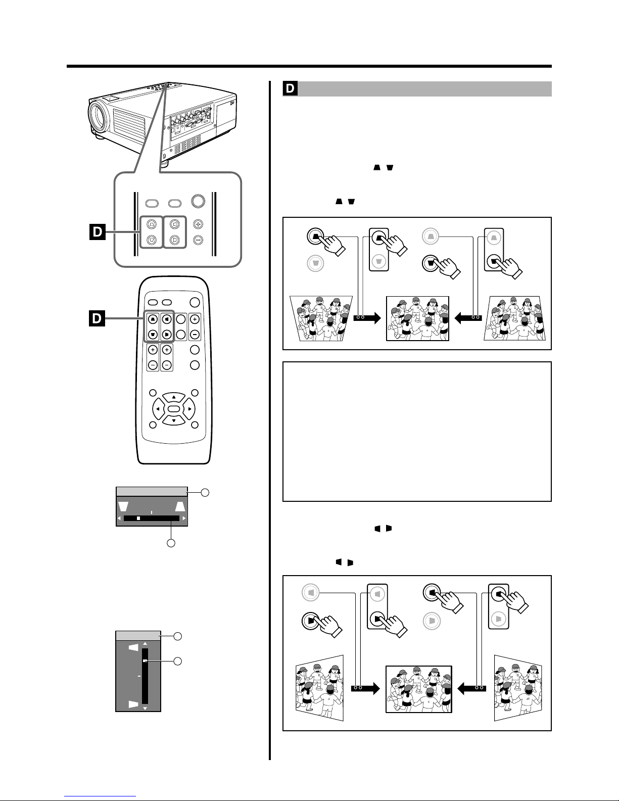
30
MENU
V-KEYSTONEPCH-KEYSTONE VOL.
EXIT
VIDEO
QUICK ALIGN.
PC VIDEO
VOLUME
PRESET HIDE
ENTER
MENU EXIT
FREEZE
OPERATE
V-KEYSTONE H-KEYSTONE
SCREEN
DIGITAL
ZOOM
FOCUS
W
S
V-KEYSTONE
V-KEYSTONE
Projector:
Control Panel
Remote Control
Unit
Projector:
Control Panel
Remote Control
Unit
V-KEYSTONE
V-KEYSTONE
H-KEYSTONE
H-KEYSTONE
H-KEYSTONE
H-KEYSTONE
Projector:
Control Panel
Remote Control
Unit
Projector:
Control Panel
Remote Control
Unit
“Vert. Keystone” Display
1 Adjusted value
range: - 100 ~ 0 ~100
2 Level displayed
level displayed is based on the adjustment value.
“Horiz. Keystone” Display
1 Adjusted value
range: -40 ~ 0 ~40
2 Level displayed
level displayed is based on the adjustment value.
Basic Operations
Removing the Trapezoidal Distortion of the Image
Depending on the angle of projection onto the screen, the image may get
distorted in a trapezoid form sometimes.
When installing the projector or screen for the first time, or when reinstalling in other rooms, etc., Keystone adjustments need to be made to
remove trapezoid distortions.
Press V-KEYSTONE / to adjust in the vertical direction.
A “Vert. Keystone” display appears on the screen, and the projector goes
into the KEYSTONE MODE.
Press button ( / ) in the direction that corrects the trapezoid form.
Notes
• The range where the trapezoidal distortion can be rectified is 30˚
vertically and 10˚ horizontally with respect to the projector screen.
However, when both are rendered together, the range of effective
rectification will be narrower.
• Depending on the signal inputted, the keystone adjustment range
may narrow or parts of the image may disappear. This is not a malfunction.
• Interference patterns may appear on the screen when adjusting the
keystone. This is not a malfunction.
•To restore the original set value, press the PRESET button. (Adjusted
value: 0)
Press H-KEYSTONE / to adjust in the horizontal direction.
A “Horiz. Keystone” display appears on the screen, and the projector
goes into the KEYSTONE MODE.
Press button ( / ) in the direction that corrects the trapezoid form.
Vert. Keystone
1
2
–12
Horiz. Keystone
1
2
12
Page 31
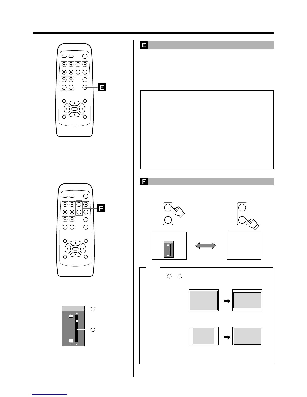
31
QUICK ALIGN.
PC VIDEO
VOLUME
PRESET HIDE
ENTER
MENU EXIT
FREEZE
OPERATE
V-KEYSTONE H-KEYSTONE
SCREEN
DIGITAL
ZOOM
FOCUS
W
S
QUICK ALIGN.
PC VIDEO
VOLUME
PRESET HIDE
ENTER
MENU EXIT
FREEZE
OPERATE
V-KEYSTONE H-KEYSTONE
SCREEN
DIGITAL
ZOOM
FOCUS
W
S
Image of 4:3
Setting the
screen size to [4:3]
Setting the
screen size to [16:9]
Image of 16:9
SCREEN
W
S
SCREEN
W
S
16 : 9 4 : 3
Note
(Original image) (Aspect ratio)
Image of 4:3
Image of 16:9
(Original image) (Aspect ratio)
● Screen size can also be adjusted from the “Options menu”. (☞ page 39)
12
W
S
Screen Pos.
● Selecting or will change the projected image as shown in
the following tables.
Basic Operations
Using the Quick Alignment function
The quick alignment function automatically adjusts (sets) the screen settings of the image input from the PC 1 or PC 2 input terminal.
● This can only be performed with the remote control.
Press the QUICK ALIGN. (Quick Alignment ) button.
During automatic alignment, “Quick Alignment” appears on the screen,
and disappears after alignment is complete.
Notes
• The “Quick Alignment” function only works when computer
signals are input into either the PC1 or PC2 input terminal.
It does not work when signals are input via a VIDEO IN terminal
(The VIDEO or Y/C input terminal).
• The Quick Alignment function.
This automatically adjusts “Horiz. disp. pos.” , “Vert. disp. pos.”,
“Phase”, “Tracking”, etc.
• Using the Quick Alignment function for automatic adjustments.
Please use with bright still-pictures. This function may not work
correctly on a dark picture or a motion-video.
If adjustment with the Quick Alignment function is not satisfactory,
adjust “Horiz. disp. pos.” and “Vert. disp. pos.”, “Phase” and “Tracking” individually.
Selecting the Screen Size
Press the SCREEN button to select the wide screen size (16:9) or the
standard screen size (4:3).
Screen size display
Displays when „ is selected. Move the image
position with the cursor button or .
1 Adjusted value
range: -30 ~ 0 ~30
2 Level displayed
level displayed is based on the adjustment value.
• When the screen mode is set to 16:9, UXGA signals cannot be projected.
1
2
12
Screen Pos.
Page 32
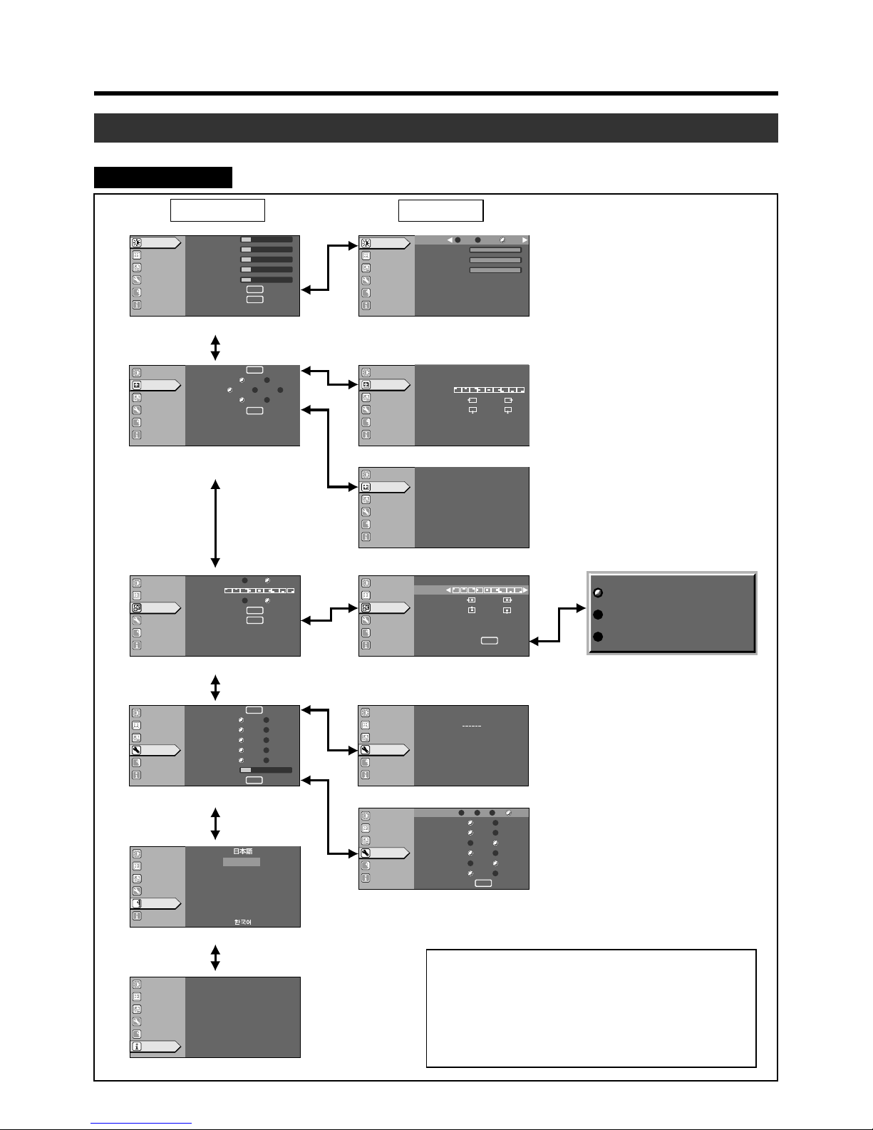
32
Adjustments and Settings Using Menus
The menus displayed on the screen are used to setup the projector and perform adjustments.
The Menu Structure
The menus of the projector have the following structure.
Video Input selection
Note
• The display language of the menus is set to “English” when
the projector is bought. The display language can be selected from among 8 languages. (☞ page 39)
However, certain phrases and nouns, etc., are displayed
only in English.
1
Main: “Image adj.” menu
3
Main: “Set up” menu
6
Main: “Logo” menu
w
Main: “Language” menu
e
Main: “Information” menu
9
Main: “Options” menu (“Page 1”)
p
“Color profile” menu
q
Main: “Options” menu (“Page 2”)
4
“
Position” menu
2
“Color temp.” menu
5
“Decoder” menu
7
“Capture menu”
8
“
Capture start”
Main menu Submenu
A
12
12
1
12
12
ENTER
ENTER
Image adj.
Set up
Logo
Options
Language
Information
Image adj.
Set up
Logo
Options
Language
Information
A
GB
R
Decoder
SECAM
PAL
NTSC4.43
NTSC
AUTO (NTSC)
Image adj.
Set up
Logo
Options
Language
Information
A
GB
R
Image adj.
Set up
Logo
Options
Language
Information
A
GB
R
ENTER
ENTER
Blue Black
OFF ON
Image adj.
Set up
Logo
Options
Language
Information
A
ENTER
(-) (+)
12
(-) (+)
12
GB
R
Image adj.
Set up
Logo
Options
Language
Information
A
GB
R
12
15sec ON
OFF ON
OFF ON
4:3 16:9
5sec OFF
ENTER
ENTER
sRGB
MacRGB
Color profile
Adobe
EBU
EXIT
Image adj.
Set up
Logo
Options
Language
Information
A
GB
R
Image adj.
Set up
Logo
Options
Language
Information
A
NTSC
Source
1234 h
Lamp time
CH.0
Switcher
VIDEO
Input
Image adj.
Set up
Logo
Options
Language
Information
A
0GREEN
0BLUE
0RED
GB
R
Color temp.
6500
STD User
Image adj.
Set up
Logo
Options
Language
Information
A
GB
R
OFF ON
OFF ON
OFF ON
9600
RGB YPbPr
Image adj.
Set up
Logo
Options
Language
Information
A
GB
R
19200
1280
1400
ENTER
Sleep time[min]
Menu color
PC2(BNC)
DIST
SCART
RS-232C[bps]
SXGA
Page 1
6015 30 OFF
Color profile
Menu display
Line display
Flip H
Flip V
Screen
Screen pos.
Page 2
Contrast
Brightness
Color
Tint
Sharpness
Color temp.
Reset
Logo disp.
Logo pos.
Back color
Logo delete
Capture menu
Capture menu
Menu pos.
Horiz.move
Vert.move
Horiz.size
Vert.size
Capture start
Capt.in prog.(approx. 2min)
Signal can not be captured
Reduce capt.size
Deutsch
Espãnol
Italiano
Français
Portugûes
A
Image adj.
Set up
Logo
Options
Language
Information
ENTER
ENTER
ENTER
ENTER
Auto OFF
1080i 1035i sF
4:31216:9
Position
Deinterlace
HDTV
Aspect ratio
Decoder
Phase
12
12
1
Position
Menu pos.
Horiz.disp.pos.
Vert.disp.pos.
Horiz.DIST.pos.
English
Page 33
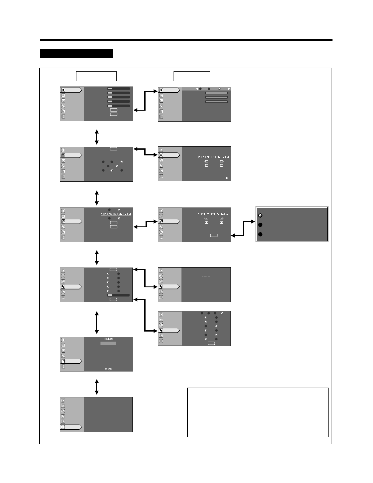
33
Adjustments and Settings Using Menus
When PC input is selected
Note
• The display language of the menus is set to “English” when
the projector is bought. The display language can be selected from among 8 languages. (☞ page 39)
However, certain phrases and nouns, etc., are displayed
only in English.
A
GB
R
EXIT
12
12
1
A
GB
R
ENTER
1:1
Panel Aspect
Low Std High
ST BP
12
123
A
1234 h
CH.0
1280 X 1024
63.98kHz
60.02 Hz
PC1
GB
R
A
12
12
1
12
12
ENTER
ENTER
Image adj.
Set up
Logo
Options
Language
Information
Image adj.
Set up
Logo
Options
Language
Information
Image adj.
Set up
Logo
Options
Language
Information
Image adj.
Set up
Logo
Options
Language
Information
A
GREEN
BLUE
RED
GB
R
Color temp.
6500
STD User
Contrast
Brightness
Color
Tint
Sharpness
Color temp.
Reset
Position
Tracking
Phase
Resize
Clamp
Sync level
Position
Menu pos.
Horiz.disp.pos.
Vert.disp.pos.
Horiz.DIST pos.
Image adj.
Set up
Logo
Options
Language
Information
A
GB
R
ENTER
ENTER
Blue Black
OFF ON
Logo disp.
Logo pos.
Back color
Logo delete
Capture menu
Image adj.
Set up
Logo
Options
Language
Information
A
ENTER
(-) (+)
12
(-) (+)
12
GB
R
Capture menu
Menu pos.
Horiz.move
Vert.move
Horiz.size
Vert.size
Capture start
Capt.in prog.(approx. 2min)
Signal can not be captured
Reduce capt.size
Image adj.
Set up
Logo
Options
Language
Information
A
GB
R
12
15sec
ON
OFF ON
OFF ON
4:3 16:9
5sec OFF
ENTER
ENTER
Color profile
Menu display
Line display
Flip H
Flip V
Screen
Screen pos.
Page 2
sRGB
MacRGB
Color profile
Adobe
EBU
EXIT
Image adj.
Set up
Logo
Options
Language
Information
A
GB
R
Image adj.
Set up
Logo
Options
Language
Information
Input
Switcher
Resolution
Frequency H
Frequency V
Lamp time
Deutsch
Espãnol
Italiano
Français
Portugûes
A
Image adj.
Set up
Logo
Options
Language
Information
OFF ON
OFF ON
OFF ON
9600
RGB YPbPr
Image adj.
Set up
Logo
Options
Language
Information
A
GB
R
19200
1280
1400
ENTER
Sleep time[min]
Menu color
PC2(BNC)
DIST
SCART
RS-232C[bps]
SXGA
Page 1
6015 30 OFF
English
0
0
0
1
Main: “Image adj.” menu
3
Main: “Set up” menu
6
Main: “Logo” menu
w
Main: “Language” menu
e
Main: “Information” menu
9
Main: “Options” menu (“Page 1”)
p
“
Color profile” menu
q
Main: “Options” menu (“Page 2”)
4
“
Position” menu
2
“
Color temp.” menu
7
“
Capture menu”
8
“
Capture start”
Main menu Submenu
Page 34
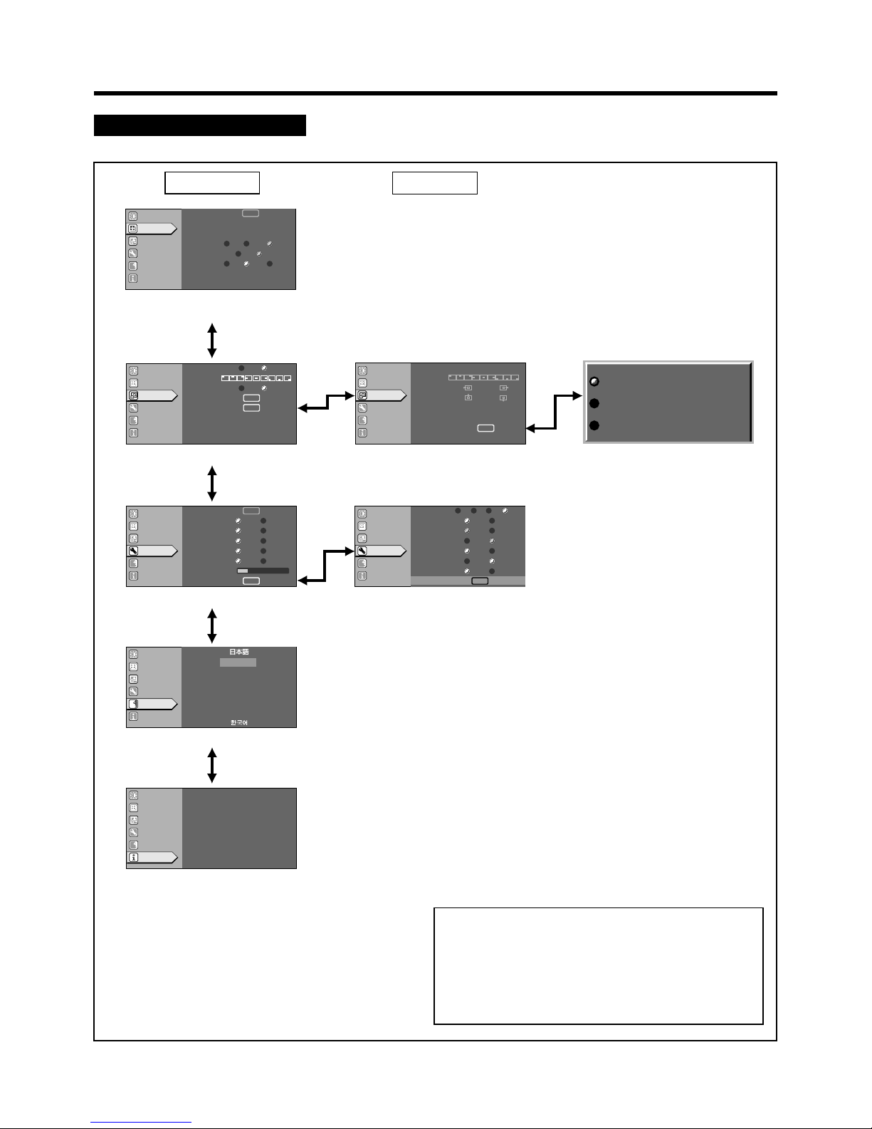
34
Adjustments and Settings Using Menus
When no image signal is inputted
Note
• The display language of the menus is set to “English” when
the projector is bought. The display language can be selected from among 8 languages. (☞ page 39)
However, certain phrases and nouns, etc., are displayed
only in English.
A
GB
R
ENTER
ENTER
1:1
Panel Aspect
Low Std High
ST BP
12
123
Image adj.
Set up
Logo
Options
Language
Information
Position
Tracking
Phase
Resize
Clamp
Sync level
Image adj.
Set up
Logo
Options
Language
Information
A
GB
R
15sec
ON
OFF ON
OFF ON
4:3 16:9
5sec OFF
ENTER
ENTER
ENTER
ENTER
Color profile
Menu display
Line display
Flip H
Flip V
Screen
Screen pos. 12
Page 2
A
1234 h
CH.0
PC1
GB
R
Image adj.
Set up
Logo
Options
Language
Information
Input
Switcher
Lamp time
Image adj.
Set up
Logo
Options
Language
Information
A
GB
R
ENTER
ENTER
ENTER
ENTER
Blue Black
OFF ON
Logo disp.
Logo pos.
Back color
Logo delete
Capture menu
Image adj.
Set up
Logo
Options
Language
Information
A
ENTER
ENTER
(-) (+)
12
(-) (+)
12
GB
R
Capture menu
Menu pos.
Horiz.move
Vert.move
Horiz.size
Vert.size
Capture start
Capt.in prog.(approx. 2min)
Signal can not be captured
Reduce capt.size
OFF ON
OFF ON
OFF ON
9600
RGB YPbPr
Image adj.
Set up
Logo
Options
Language
Information
A
GB
R
19200
1280
1400
6015 30 OFF
Deutsch
Espãnol
Italiano
Français
Portugûes
A
Image adj.
Set up
Logo
Options
Language
Information
English
ENTER
ENTER
Sleep time[min]
Menu color
PC2(BNC)
DIST
SCART
RS-232C[bps]
SXGA
Page 1
3
Main: “Set up” menu
9
Main: “Options” menu (”Page 1”)
w
Main: “Language” menu
e
Main: “Information” menu
q
Main: “Options” menu (“Page 2”)
Main menu
Submenu
6
Main: “Logo” menu
7
“
Capture menu”
8
“
Capture start”
Displayed only when PC is selected.
Page 35
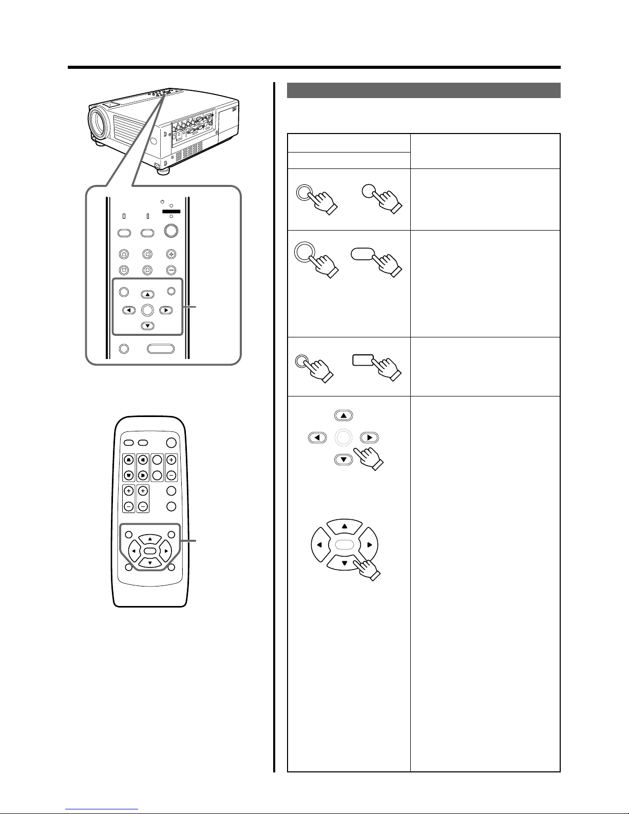
35
QUICK ALIGN.
PC VIDEO
VOLUME
PRESET HIDE
ENTER
MENU EXIT
FREEZE
OPERATE
V-KEYSTONE H-KEYSTONE
SCREEN
DIGITAL
ZOOM
FOCUS
W
S
PRESET
MENU
V-KEYSTONE
PC
LAMP
H-KEYSTONE VOL.
EXIT
ENTER
HIDE
VIDEO
TEMP
STAND BY
OPERATE
Menu
operation
button
Menu
operation
button
MENU
MENU
ENTER
EXIT
ENTER
ENTER
Main unit
ENTER
Remote control unit
Adjustments and Settings Using Menus
The Menu Operation Buttons
The menus are accessed and operated using the following buttons on
the projector/remote control:
Button
Main unit
Remote control unit
Function
EXIT
Displays the main menu on the
screen.
• When the main menu is displayed,
press to exit the menu mode.
Select an item while the main menu
(hierachy1)is displayed; the submenu
(hierachy 2) corresponding to the
item selected will be displayed on the
screen.
Press to shift to the “Set up” screen
(hierachy3) of the selected item
against which “ENTER” is displayed.
Press to return to the previous menu.
• While the main menu is displayed,
press to exit the menu mode.
While the main menu and submenus (“Image adj.”, “Set up”,
“Options”, “Logo”) are displayed
䊱/䊲
: Selects an adjustment item
in the menu.
䊴/䊳
: Sets the value of the item
selected.
The adjusted set value is
immediately reflected on
the image.
While the “Language”, “Decoder”
or “Color profile” submenus are
displayed
䊱/䊲
: Selects an item in the menu.
䊴/䊳
: No effect.
Page 36
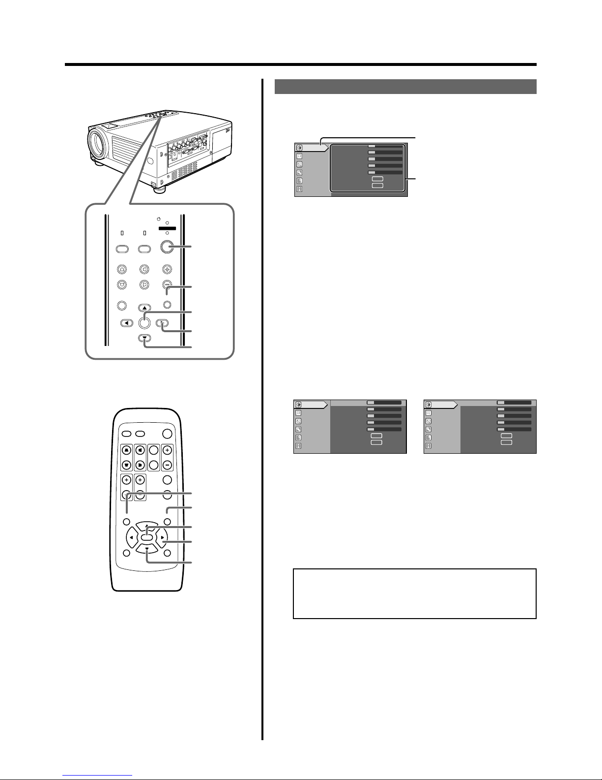
36
QUICK ALIGN.
PC VIDEO
VOLUME
PRESET HIDE
ENTER
MENU EXIT
FREEZE
OPERATE
V-KEYSTONE H-KEYSTONE
SCREEN
DIGITAL
ZOOM
FOCUS
W
S
MENU
V-KEYSTONE
PC
LAMP
H-KEYSTONE VOL.
MENU
EXIT
ENTER
VIDEO
TEMP
STAND BY
OPERATE
2, 4
3, 5
6
1
5
1
6
2, 4
3, 5
5
A
12
12
1
12
12
ENTER
ENTER
Image adj.
Set up
Logo
Options
Language
Information
Contrast
Brightness
Color
Tint
Sharpness
Color temp.
Reset
A
12
12
1
12
ENTER
ENTER
Image adj.
Set up
Logo
Options
Language
Information
Contrast
Brightness
Color
Tint
Sharpness
Color temp.
Reset
12
A
12
12
1
12
ENTER
ENTER
Image adj.
Set up
Logo
Options
Language
Information
Contrast
Brightness
Color
Tint
Sharpness
Color temp.
Reset
12
The Procedure for Menu Operation
1.
Press the MENU button.
The main menu is displayed on the screen.
4.
Press the CURSOR buttons (䊱/䊲) to select an adjustment item.
Item names in submenus displayed in pale cannot be selected.
5.
Press the CURSOR buttons (䊴/䊳) to change the setting
value.
6.
To EXIT after the adjustment, press the EXIT button.
Each time you press the button, the menu returns to the previous
one.
7.
Repeat procedures 2 to 6 to set other items.
After all adjustments are done,
Press the MENU button.
The menu will disappear from the screen.
The menu item that has been selected is displayed.
The icon of the selected menu item
will be highlighted.
The submenu is displayed.
2.
Press the CURSOR buttons (䊱/䊲) to select a submenu.
• The “Image adj.”, “Set up”, “Logo”, “Options” and “Language”
submenus are displayed.
• When “Information” is chosen, the image input or PC input information (whichever is currently selected) is displayed on the right
of the menu.
• When “Language” is selected, you can set the language. ➔
Proceed to Procedure 6.
3.
Press ENTER button or the right CURSOR button (䊳).
• The submenu is displayed on the screen.
• The submenu indicated differs according to whether Video input
or PC input is selected, or when there is no image signal inputted.
For details, please see ‘The Menu Configuration’ on the next page.
E.g. Main menu when video input is
selected: “Image adj.”.
Alternatively, press ENTER.
• When the item in the image adjustment menu against which
“ENTER” is indicated is selected, either it will shift to the set
up screen or the item command will be executed.
E.g. “Image adj.” menu when video
input is selected.
E.g. “Image adj.” menu when PC in-
put is selected.
Adjustments and Settings Using Menus
Page 37
37
Adjustment and Setting Using Menus
3 “Set up” menu
Use this menu to set the basic Tracking and Positioning settings
of a picture image. Items that can be adjusted via the “Set up”
menu are shown below.
• Adjustment items differ depending on whether Video input or
PC input is selected.
When Video input is selected
Adjustment item (press䊱/䊲) Adjustment content (press䊴/䊳)
“Position” The position of the image and the menu
can be adjusted.
[ Press the ENTER button to enter the
“Position” menu 4.
“Deinterlace” This is set when viewing movies.
“Auto” : Normally, the projector is set to
Auto.
“OFF” : This is set when not viewing
movies.
“HDTV” In order to display “HDTV” signals in the
exact aspect ratio of 16:9, the correct numerical value has to be set.
“1080i” : Normally, set to 1080i.
“1035i” : Set when high vision signals are
used.
“sF” : Used for segment frame signals.
“Aspect ratio” Select the vertical-to-horizontal ratio of
the image projected.
Set it to 4:3 for normal television image
input and 16:9 for Hi-Vision input.
When the “Screen” mode is set to 16:9,
UXGA signals cannot be projected.
Values: 4:3, 16:9 [4:3]
“Decoder” Sets the “Decoder”.
[ Press the ENTER button to enter the
“Decoder” menu 5.
“Phase” Adjusts flickering or dim images.
(setting is normally not required.)
Range of values : 0 ~ 31
[Varies with signals]
When PC input is selected
Adjustment item (press䊱/䊲) Adjustment content (press䊴/䊳)
“Position” Adjusts the position of the image and
menu display.
[ Press ENTER to go to the “Position”
menu 4.
“Tracking” Adjusts lateral size and display area of
image. (Setting is normally not required.)
[Varies with signal]
“Phase” Adjusts flickering or dim image.
(adjustment is normally not required.)
Range of values : 0 ~ 40
[Varies with signals]
“Resize” When the image resolution is smaller than
that of the projector’s D-ILA element, the
projected image will be enlarged to almost
the full screen size.
Range of values : *“1:1”, “Panel”, “Aspect”
[“Aspect”]
1 “Image adj.” menu
Image adjustment.
You can adjust the following items on the “image adj.” menu.
• The items displayed differ depending on whether Video input
or PC input is selected.
• There is no display when no image signal is inputted.
Adjustment item (press䊱/䊲) Adjustment content (press䊴/䊳)
“Contrast” Adjusts the contrast of the picture image.
Range of values: -30~30 [0]
“Brightness” Adjusts the brightness of the picture im-
age. Range of values: -30~30 [0]
“Color” Adjusts the color density of the picture
image. Range of values: -30~30 [0]
“Tint” Adjusts the tint of the picture image.
Range of values: -30~30 [0]
“Sharpness”* Adjusts the outline of the picture image.
Range of values: -3~3 [0]
“Color temp.” Adjust the Color temperature of the
screen.
[ Press ENTER button to go into the
Color temperature setting menu.
“Reset” Resets all items in the “Image adj.”
submenu to the pre-set values( ie values
set upon purchase).
[ Press ENTER button to reset.
* In the “Set up” menu 3, if the “Resize” function in the PC submenu is
set to “1:1”, the image quality will not change even if the value is
changed. (No adjustment)
2 “Color temp.” menu
To adjust the “Color temp.” of the projected image, press the
(
䊱/䊲
) CURSOR buttons and choose the setting. Next press
the (䊴/䊳) CURSOR buttons to set the “Color temp.”. If “6500”
is set, the image will turn out reddish.
Set value: “6500”, “Normal”, “User” [“User”]
“RED” : –255 ~ 0 [0]
“GREEN” : –255 ~ 0 [0]
“BLUE” : –255 ~ 0 [0]
The Menu Configuration
Item values shown in [ ] are initial values set at manufacture.
• Press ENTER, EXIT or the right CURSOR button (䊳) to op-
erate a MENU while it is displayed.
• The submenu corresponding to an item currently selected is
displayed on the right-hand side of the main menu.
• Menu items shown differ according to whether Video input or
PC input is selected or when there is no image signal inputted.
• When “Information” is selected, information relating to the
present selected image input appears on the right side of the
menu.
There is no submenu for this “Information” menu. (For details,
please See ‘Main: “Information” menu’ on page 40.)
When Video input is selected When PC input is selected
Page 38
38
“Clamp” This can be used if the screen of the PC/
workstation is unstable in that it dims and
brightens.
Set the position of the clamp pulse to
Back porch (“BP”) or Sync tip (“ST”).
Normally, “BP” is used.
Values: “ST”, “BP” [“BP”]
“Sync Level” Although the inputted image signal is
adjusted so that synchronization occurs
automatically, this changes by changing
the “Sync level” setting.
Setting can be made by selecting “Low”
(weaker), “Std” (factory set) or “High”
(stronger).
Values: “Low”, “Std”, “High” [“Std”]
* “1.1” : The image is displayed at the inputted resolution.
“Panel” : The picture image projected is virtually enlarged to
the full screen size if the inputted resolution is smaller
than (1400 pixels x 1050 pixels).
“Aspect” : While maintaining the original aspect ratio, the video
image projected is virtually enlarged until either the
horizontal or vertical side reaches the full size (1400
pixels x 1050 pixels).
When there is no image signal inputted
Adjustment item (press䊱/䊲) Adjustment content (press䊴/䊳)
“Sync level” Although the inputted image signal is
adjusted so that synchronization occurs
automatically, this changes by changing
this setup.
Setting can be made by selecting “Low”
(weaker), “Std” (factory set) or “High”
(stronger).
Values: “Low”, “Std”, “High” [“Std”]
4 “Position” menu
Adjusts the menu display position. Press the (䊱/䊲) CURSORS
to set the horizontal/vertical position of the menu display.
Set Value:
“Menu pos.”:
“Horiz. disp. pos.” : Varies with signals.
“Vert. disp. pos.” : Varies with signals.
“Horiz. DIST pos.” : - 8 ~ + 7 [0]
5 “Decoder” menu
Press the (䊱/䊲) CURSOR buttons to choose the “Decoder” of
the image signals. Normally, “Auto” is selected. When “Auto” does
not function well, select the appropriate decoder accordingly.
Values: “AUTO”, “NTSC”, “NTSC4.43”, “PAL”, “SECAM”
[“AUTO”]
6 “Logo” menu
Adjustment item (press䊱/䊲) Adjustment content (press䊴/䊳)
“Logo disp.” Sets whether to indicate the user set logo
(captured image: “Logo disp.”) when the
projector starts up.
[“ON”]
“Logo pos.” Sets the position of the user set logo (cap-
tured image: “Logo disp.”) when the projector starts-up. Re-setting can be performed only when the logo has been
eliminated.
Set value:
“Logo pos.”:
¥¥¥¥¥¥¥¥
“Back color” Selects the background color of the user
set picture (captured image: “Logo disp.”).
[“Black”]
Re- setting can be performed only when
the logo has been eliminated.
“Logo delete” Deletes the user set logo (captured
image: “Logo disp.”). Deletion takes a few
seconds.
[ Press the ENTER button to delete.
“Capture menu” You can project a picture from the video
player or PC and capture it to use as your
logo.
The captured picture can be displayed as
a logo display when the projector starts
up.
[ Press the ENTER button to go into
the “Capture menu” screen.
7 “Capture menu”
Adjustment item (press䊱/䊲) Adjustment content (press䊴/䊳)
“Menu pos.” Adjusts the display position of the cap-
ture menu.
Set value:
“Menu pos.”:
¥¥¥¥¥¥¥¥
“Horiz. move” The position of the picture that you want
to capture can be moved left/right with the
CURSOR buttons (䊴 / 䊳).
“Vert. move” The position of the picture that you want
to capture can be moved up/down with
the CURSOR buttons (䊱 / 䊲).
“Horiz. size” The width of the picture that you want to
capture can be set by the CURSOR buttons (䊴 / 䊳).
“Vert. size” The height of the picture that you want to
capture can be set by the CURSOR buttons (䊱 / 䊲).
“Capture start” After setting all the items of the capture
menu, image capture starts.
❈ Note that images already inputted will
be deleted.
[ Press the ENTER button to start.
Adjustments and Settings Using Menus
[ ]
[ ]
[ ]
¥¥¥¥¥¥¥¥
Page 39
39
8 “Capture start”
The status of capture is displayed in bold.
“Capt. in prog. (Approx. 2min)”
The image is being read into the projector. During this time interval, the projector will not respond to any command signal inputted by the user.
“Signal can not be captured”
Clear the message with the EXIT button
and input appropriate signals.
“Reduce capt. size”
Clear the message with the EXIT button
and decrease the signal size.
❈ Depending on the image content, there
will be cases where certain signals cannot be captured while others of the
same size can be.
9 “Options” menu (q)
The items of the “Options” menu shown below can be adjusted.
• The “Options” menu consists of two pages (“Page 1” and “Page
2”).
“Page 1”
Adjustment item (press䊱/䊲) Adjustment content (press䊴/䊳)
“Color profile” Sets the color table.
[ Press the ENTER button to go into the
color profile menu p .
“Menu display” Sets whether the menu display automati-
cally clears after 15 seconds.
Values: “15sec”, “ON” [“15sec”]
“Line display” Sets whether the line display is shown for
about 5 seconds.
Values: “5sec”, “OFF” [“5sec”]
“Flip H” Reverses image left to right.
Values: “ON”, “OFF” [“OFF”]
“Flip V” Inverses image upside down.
Values: “ON”, “OFF” [“OFF”]
“Screen” Sets the projected screen size.
Values: 4:3, 16:9 [4:3]
“Screen pos.” Sets the display position when the
“Screen” is set to [16:9].
Values: -30~30 [0]
“Page 2” Displays “Page 2” of the “Option” menu.
[ press ENTER to go the “Option” menu
(“Page 2”) screen q.
p “Color profile” menu
To choose the color table of the image signals, press the (䊱 / 䊲)
CURSOR buttons. When using “Color profile”, set the “Color
temp.” to “6500”.
• No display in the absence of image signal input.
Values: “------”, “sRGB”, “MacRGB”, “Adobe”, “EBU”
[“------”]
Adjustments and Settings Using Menus
q “Page 2”
Adjustment item (press䊱/䊲) Adjustment content (press䊴/䊳)
“Sleep time [min]” Sets the length of sleep time which, when
lapsed, automatically puts the projector
into stand-by state if no signal is inputted.
Setting value: 15,30,60,“OFF” [“OFF”]
“Menu color” When “ON”, menu becomes transparent and
the background can be seen through it.
Setting value: “OFF”, “ON” [“OFF”]
“PC2 (BNC)” Sets whether to use the BNC connector
on the back of the projector as an “RGB”
signal input terminal or as a “YPBPR”
(color-difference) signal input terminal.
Please reset it based on the connected
apparatus.
❈ The input will be “RGB” irrespective of
the PC signal setting.
Setting value: “RGB”, “YPBPR” [“RGB”]
“DIST” Image of high resolution can be achieved.
Set as required.
This is turned “ON” when the OPERATE
button is pressed.
Setting value: “OFF”, “ON” [“ON”]
“SCART” Connects to a Europe-adapted SCART
plug and turns it “ON” during component
input.
Connect the Image Signal cable to the
RGB terminal of the PC2 input terminal
and the Sync Signal cable to the VIDEO
IN terminal.
Setting value: “OFF”, “ON” [“OFF”]
“RS-232C [bps]” Sets the communication speed (signal
transmission speed) when communicating with a computer by using the RS-232C
terminal. Please set the baud rate for
transmission.
Setting value: 9600,19200 [19200]
“SXGA” Setting value: 1280,1400 [1280]
“Page 1” Display “Page 1” of “Options” menu.
[ Press the ENTER button to go to “Op tions” menu (“Page 1”) screen9.
w “Language” menu
Select the language in this language menu with the CURSOR
buttons (
䊱
/ 䊲).
Setting value : “ ” (Japanese), “English”, “Deutsch” (Ger-
man), “Espanol” (Spanish), “Italiano” (Italian),
“Francais” (French), “Portugues” (Portuguese)
and “
” (Korean).
[“English”]
❈ Some words in the menu and proper nouns such as “VIDEO”,
“NTSC”, “Quick Alignment” are shown only in English.
Page 40
40
e “Information” menu
When video input is selected
Adjustment item (press䊱/䊲) Adjustment content (press䊴/䊳)
“Input” Displays the image input (VIDEO, Y/C,
PC2) when projecting.
“Switcher” Displays the selected switcher matching
the specification of this projector.
0 : not being used.
1-10 : switcher number.
❈ For details, please check with your au
thorized dealer.
“Source” Displays the type of video signal of the
image projected.
“Lamp time” Displays the number of accumulated used
hours of the light-source lamp.
When PC input is selected
Adjustment item (press䊱/䊲) Adjustment content (press䊴/䊳)
“Input” Displays the computer input (PC1, PC2,
PC3) when projecting.
“Switcher” Displays the selected switcher number
matching the specification of this projector.
0 : not being used.
1-10 : switcher number.
❈ For details, please check with your au
thorized dealer.
“Resolution” Displays the resolution of the inputted sig-
nal. (Horizontal x vertical)
❈ Some inputted signals cannot be dis
played correctly.
“Frequency H” Displays the horizontal frequency of the
inputted signal.
“Frequency V” Displays the vertical frequency of the in-
putted signal.
“Lamp time” Displays the number of accumulated used
hours of the current light-source lamp.
When no image signal is inputted
Adjustment item (press䊱/䊲) Adjustment content (press䊴/䊳)
“Input” Displays the current selected image in-
put (VIDEO, Y/C, PC1, PC2, PC3) when
projecting.
“Switcher” Displays the selected switcher number
matching the specification of this projector.
0: not being used
1-10 : switcher number.
❈ For details, please check with your au
thorized dealer.
“Lamp time” Displays the number of accumulated used
hours of the light-source lamp.
Adjustments and Settings Using Menus
Page 41
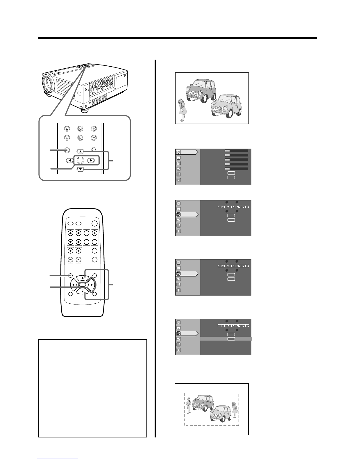
41
MENU
V-KEYSTONE H-KEYSTONE VOL.
EXIT
ENTER
2
2
3,5
4
QUICK ALIGN.
PC VIDEO
VOLUME
PRESET HIDE
ENTER
MENU EXIT
FREEZE
OPERATE
V-KEYSTONE H-KEYSTONE
SCREEN
DIGITAL
ZOOM
FOCUS
W
S
3,5
4
Notes
• Setting the logo display item in the “Logo”
menu to “ON” and switching on the power displays the D-ILA logo and then the user-set
logo. (Factory setting is “ON”)
• When the D-ILA or user-set logo is displayed
after the projector is turned on, pressing the
EXIT button will delete the logo.
• During video signal input, pressing the EXIT
button on the remote control unit when the
menu is not displayed causes the logo to appear.
Press any other button to delete the logo from
the screen.
Editing and Projecting Logo
You can project your logo if you like when you start up the projector.
This may come in useful during presentations, etc.
1.
Project the images to be included in your logo.
2.
Press the MENU button.
• The main menu appears on the screen.
3.
Select “Logo” with the CURSOR buttons (䊱 / 䊲).
4.
Press the ENTER or the right CURSOR button ( 䊳).
• The “Logo” menu appears on the screen.
5.
Select “Capture menu” with the CURSOR buttons (䊱 / 䊲)
and press ENTER.
6.
The captured picture appears on the screen.
• The captured picture (i.e your logo) with a frame appears on the
screen.
Screen display
MOTOR SHOW
A
12
12
1
12
12
ENTER
ENTER
Image adj.
Set up
Logo
Options
Language
Information
Contrast
Brightness
Color
Tint
Sharpness
Color temp.
Reset
Image adj.
Set up
Logo
Options
Language
Information
A
GB
R
ENTER
ENTER
Blue Black
OFF ON
Logo disp.
Logo pos.
Back color
Logo delete
Capture menu
Image adj.
Set up
Logo
Options
Language
Information
A
GB
R
ENTER
ENTER
Blue Black
OFF ON
Logo disp.
Logo pos.
Back color
Logo delete
Capture menu
Image adj.
Set up
Logo
Options
Language
Information
A
GB
R
ENTER
ENTER
Blue Black
OFF ON
Logo disp.
Logo pos.
Back color
Logo delete
Capture menu
ENTER
ENTER
Screen display
Page 42
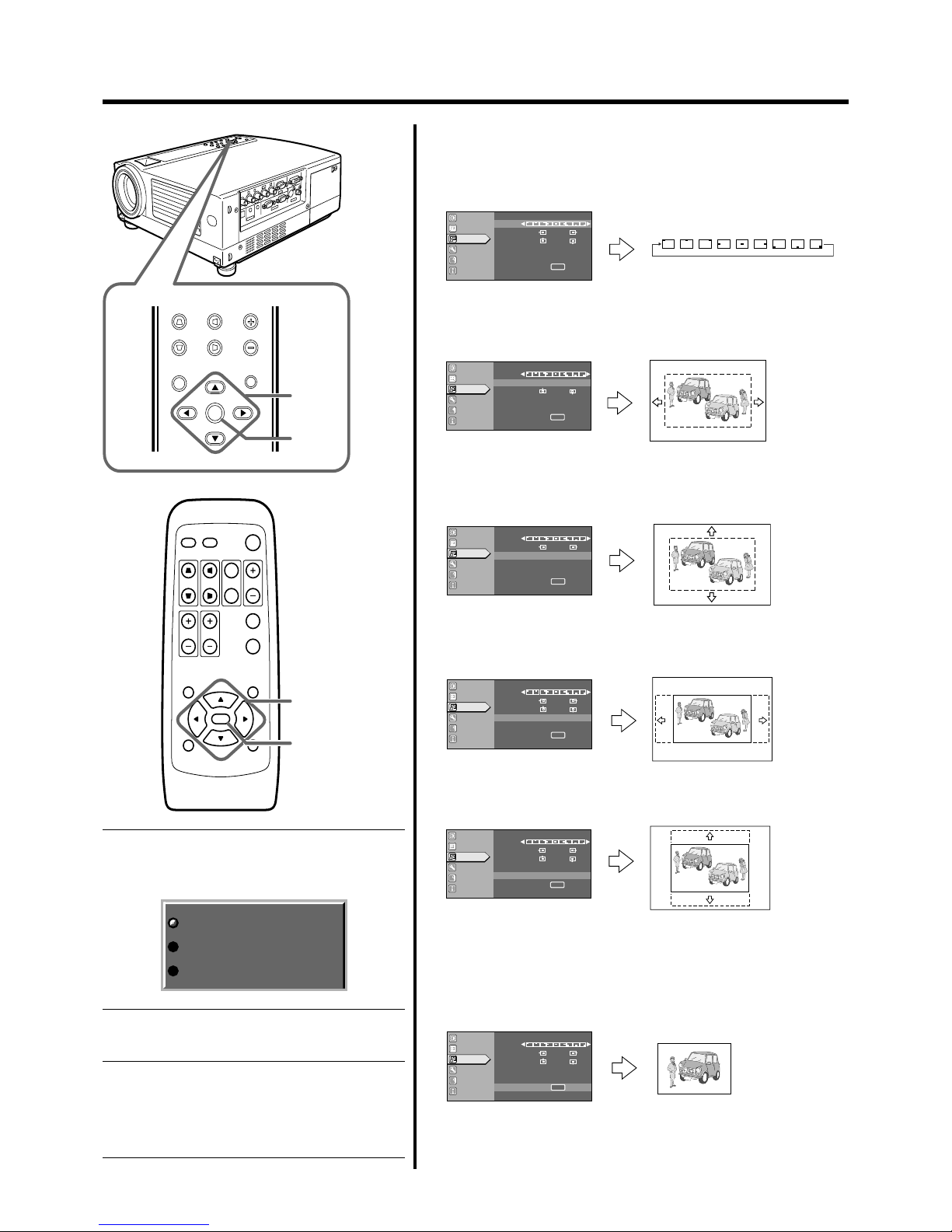
42
MENU
V-KEYSTONE H-KEYSTONE VOL.
EXIT
ENTER
1~6
6
QUICK ALIGN.
PC VIDEO
VOLUME
PRESET HIDE
ENTER
MENU EXIT
FREEZE
OPERATE
V-KEYSTONE H-KEYSTONE
SCREEN
DIGITAL
ZOOM
FOCUS
W
S
1~6
6
´
´
´´´´´ ´
Image adj.
Set up
Logo
Options
Language
Information
A
ENTER
ENTER
(-) (+)
12
(-) (+)
12
GB
R
Capture menu
Menu pos.
Horiz.move
Vert.move
Horiz.size
Vert.size
Capture start
Image adj.
Set up
Logo
Options
Language
Information
A
ENTER
ENTER
(-) (+)
12
(-) (+)
12
GB
R
Capture menu
Menu pos.
Horiz.move
Vert.move
Horiz.size
Vert.size
Capture start
Image adj.
Set up
Logo
Options
Language
Information
A
ENTER
ENTER
(-) (+)
12
(-) (+)
12
GB
R
Capture menu
Menu pos.
Horiz.move
Vert.move
Horiz.size
Vert.size
Capture start
Image adj.
Set up
Logo
Options
Language
Information
A
ENTER
ENTER
(-) (+)
12
(-) (+)
12
GB
R
Capture menu
Menu pos.
Horiz.move
Vert.move
Horiz.size
Vert.size
Capture start
Image adj.
Set up
Logo
Options
Language
Information
A
ENTER
ENTER
(-) (+)
12
(-) (+)
12
GB
R
Capture menu
Menu pos.
Horiz.move
Vert.move
Horiz.size
Vert.size
Capture start
Image adj.
Set up
Logo
Options
Language
Information
A
(-) (+)
12
(-) (+)
12
GB
R
Capture menu
Menu pos.
Horiz.move
Vert.move
Horiz.size
Vert.size
Capture start
ENTER
ENTER
Editing and projecting logo
1.
Set the menu position as required.
• Select “Menu pos.” with the CURSOR buttons (䊱 / 䊲).
•Move the menu display position with the CURSOR buttons
(䊴 / 䊳) while viewing the projected image.
2.
Select “Horiz. move” with the
CURSOR
buttons (䊱 / 䊲).
•Move the logo left or right with the CURSOR buttons (䊴 /䊳)
while viewing it on the screen.
3.
Select “Vert. move” with the CURSOR buttons (䊱 / 䊲).
•Move the logo up or down with the CURSOR buttons (䊴 / 䊳)
while viewing it on the screen.
4.
Select “Horiz. size” with the CURSOR buttons (䊱 / 䊲).
• Set the width with the CURSOR buttons (䊴 / 䊳) while viewing
the projected image.
5.
Select “Vert. size” with the CURSOR buttons (䊱 / 䊲).
• Set the height with the CURSOR buttons (䊴 / 䊳) while viewing
the projected image.
6.
Select “Capture start” with the CURSOR buttons (䊱 / 䊲)
and press ENTER.
• Begin to capture the framed image set in the procedures 2 to 5
from the projected image.
• The captured picture wil be taken into memory as a logo in the
projector and will be shown during start-up.
“Capt. in prog. (Approx. 2min)”
The image is being read into the projector. During this time
interval, the projector will not respond to any command
signal inputted by the user.
“Signal can not be captured”
Clear the message with the EXIT button and input appropriate signals.
“Reduce capt. size”
Clear the message with the EXIT button and decrease
the signal size.
❈ Depending on the image content, there will be cases
where certain signals cannot be captured while others
of the same size can be.
Capt.in prog.(approx. 2min)
Signal can not be captured
Reduce capt.size
Page 43
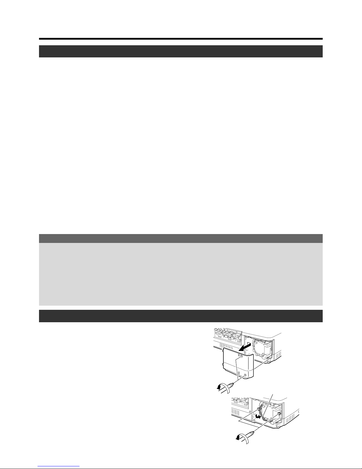
43
Handle
䡵 When lamp time exceeds 1000 hours:
When the accumulated lamp time reaches 1000, a message
indicating “1000 h” will appear on the projected screen.
* Press any key to delete the message.
䡵 When lamp time exceeds 1900 hours:
• When the accumulated lamp time reaches 1900 hours:
The LAMP indicator on the projector lights up.
• When the accumulated lamp time exceeds 1900 hours:
“Lamp replacement” appears on the screen.
* Press any button to delete the message.
Replacing the Lamp
The light source lamp and its lamp time
The light-source lamp has a service life. The life of lamps currently used for this projector is about 2000 hours.
[Average lamp life: 2000 hours]
When the light-source lamp approaches the end of its service life, deterioration progresses rapidly. Please install a new lamp when
the accumulated lamp time exceeds 1900 hours or at least get a replacement lamp ready. Depending on the operating conditions,
the lamp may have to be changed earlier. If the image remains dark or the tone, unusual, even after adjustment, please replace the
lamp as soon as possible. You can check the accumulated used hours of the lamp via the “Lamp Time” item in the “Information”
menu. (☞ page 40)
Please purchase the new lamp unit from the authorized dealer where you purchased the projector.
Exchange lamp Part No.: BHL5006-S
The procedure for lamp replacement
1.
Loosen the screws and detach the light-source lamp cover.
Loosen the two screws with a ª screwdriver.
2.
Loosen the screws and lift up the handle.
Loosen the two screws with a ª screwdriver.
䡵 When the lamp time exceeds 2000 hours:
The lamp indicator on the projector blinks.
“Warning” and “Lamp replacement” appear on the screen;
the word “Warning” blinks.
❈ To cancel the message, press the EXIT button.
However, the same message will appear again every one hour.
❈ Once the lamp time exceeds 2000 hours, and the projec
tor is either put into the standby state or turned off, projec
tion will not be possible again until the lamp is replaced
and the “Lamp time” is reset. (☞ page 45)
䡵 When the lamp time exceeds 2010 hours:
The projector quits and shuts down.
The LAMP and OPERATE indicators blink on the projector.
❈ The projector does not turn on unless the lamp (lamp unit)
is replaced and the “Lamp time” is reset. (☞ page 45)
About lamp replacement
● If the projector is set in a constricted place, attempting to replace the lamp in that place could cause injury. Move the projector
to a place large enough to work in.
● To avoid malfunctions, be sure to use only genuine replacement parts. Also, never attempt to re-use an old lamp as this could
cause marked performance deterioration or lamp blow-out leading to projector malfunction. In the worse case, broken pieces
of glass from the lamp may cause injuries.
● Do not replace the lamp immediately after the projector has been used. The temperature of the lamp unit is still high and
could cause a burn. Allow a cooling period of one hour or more before replacement.
● Before starting to replace the lamp, disconnect the power cord from the wall outlet while the STAND BY indicator is on.
Replacing a lamp while the power cord is connected could cause injury or electric shocks.
Page 44
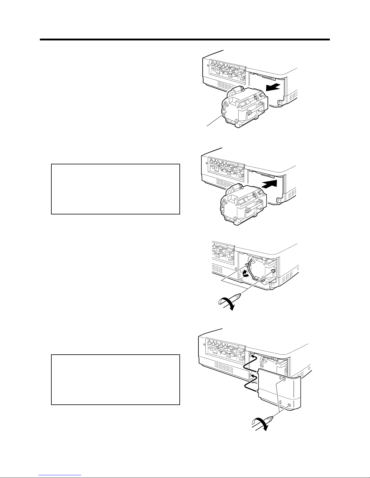
44
Lamp unit
3.
Remove the lamp unit.
Replacing the Lamp
4.
Insert the new lamp unit until it is fully in.
5.
Close the handle, and tighten the screw.
Tighten the two screws with a ª screwdriver.
6.
Attach the light-source lamp cover and tighten
the screw.
Tighten the two screws with a ª screwdriver.
Note
• When closing the lamp cover, please insert the left
side (with the two claws) in first and then ensure that
the protruding part found on the reverse side of the
cover fits snugly into the hole of the main unit. As
this protrusion acts as a switch, misfitting leads to
power not being able to flow in.
Caution
• Neither touch the glass surface of the lamp directly
with your hand nor stain it. If you touch it with a bare
hand, oil or other substances on your hand may adhere to the lamp, possibly preventing it from performing as specified and therefore lead to a shortened
lamp life, a darkened screen, etc.
Page 45
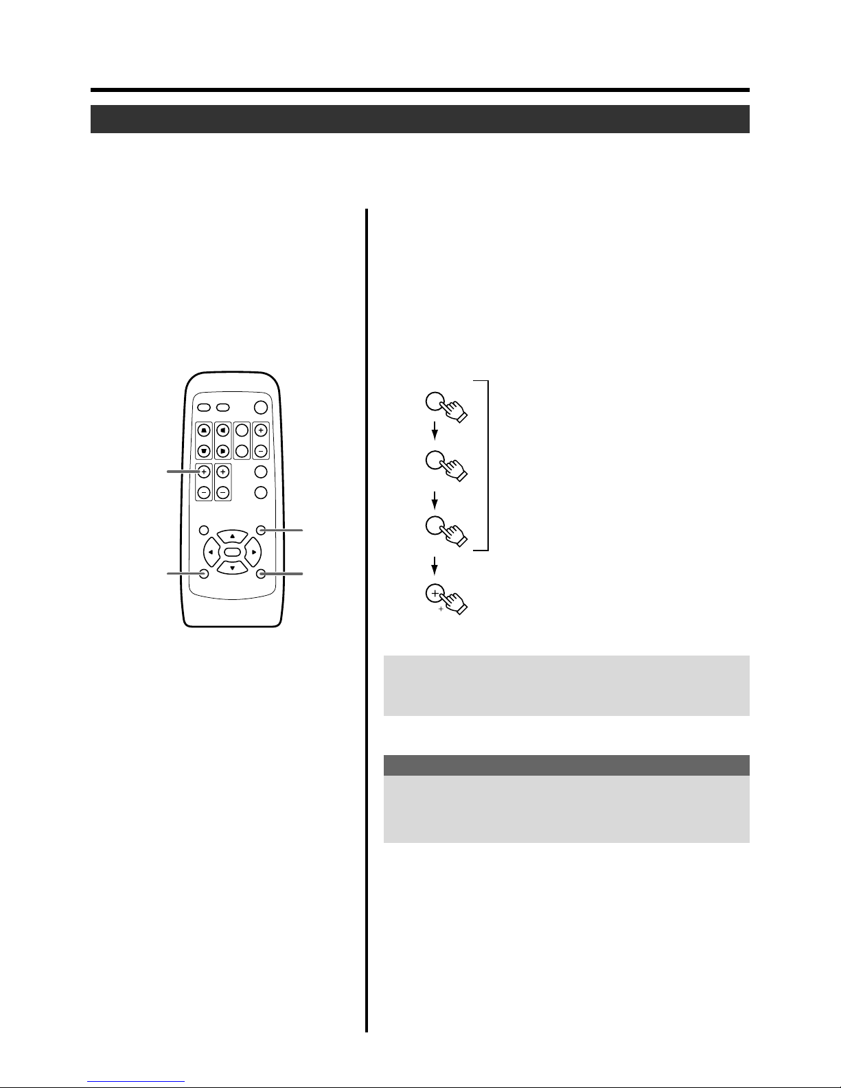
45
QUICK ALIGN.
PC VIDEO
VOLUME
PRESET HIDE
ENTER
MENU EXIT
FREEZE
OPERATE
V-KEYSTONE H-KEYSTONE
SCREEN
DIGITAL
ZOOM
FOCUS
W
S
PRESET HIDE
EXIT
press for
2 seconds
EXIT
PRESET
HIDE
VOL( )
Press as per normal
Press for 2 seconds or more
Replacing the Lamp
1.
Insert the main plug. The projector will go into the stand
by mode.
ON: STAND BY indicator lights up.
2.
Press the EXIT, HIDE, PRESET buttons on the remote
control sequentially, then press VOL ª for 2 seconds or
more.
The STAND BY and OPERATE indicators alternately blink about
every approx.3 seconds. After blinking stops, “Lamp time” resets
and the projector returns to the stand-by state (STAND BY indicator
lights up).
Resetting the lamp time
After installing a new lamp, reset the “Lamp time” counter inside the projector.
When this is done, a new count will start.
If the display of the accumulated lamp time has reached 2000 hours, the projector will not work (lamp does not light up) unless the
lamp time is reset.
To ensure the lamp time has been reset.
The Lamp time can be checked via the “Lamp time” item in the “Information” menu. (☞ page 32, 33, 34, 40)
Caution for reset work
Reset the “Lamp time” only when you have replaced the lamp.
Never reset it while the lamp is still in use, otherwise the approximate standard for gauging replacement time may be inaccurate, lamp
performance may suffer and lamp blow-out may also occur.
Page 46
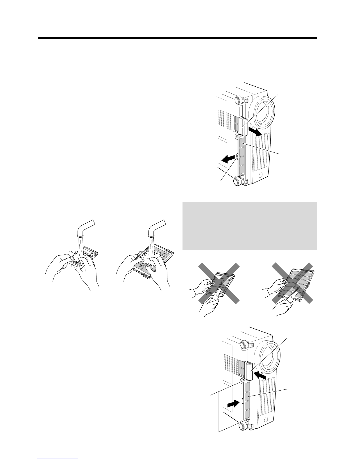
46
lower filter
inner filter
claw
lower filter
inner filter
claw
● Put on rubber gloves when using a neutral detergent.
● After you wash a filter in water, make sure that the filter is
completely dry before reinstalling, otherwise electric
shocks or malfunctions may occur.
● Do not clean removable filters with a vacuum cleaner.
Since these filters are soft, they can be sucked into the
vacuum cleaner or otherwise damaged.
Cleaning and Replacing the Filter
Clean the filter regularly or it may not work satisfactorily, causing damage. If the filter is extremely dirty and cannot be cleaned, or
if it is damaged, replace the filter with a new one (Lower filter: LC32087-001/ Inner filter:LC32058-001). Otherwise, dirt may get
inside the unit and appear on the screen, preventing you from enjoying the video fully. If dirt has gotten in or if you need information
about the filter, please consult the authorized dealer where you purchased the projector.
❈ The air inlet filter on the right side cannot be removed. Please clean this filter regularly using, for example, a vacuum
cleaner.
1.
Pull out the power cord from the wall outlet.
After the projector goes into the stand-by state with the
STAND BY indicator on, pull out the power cord from the
wall outlet.
2.
Remove the filter.
• When removing the lower filter:
Withdraw the lower filter backwards along the rail in the
direction of the arrow.
• When removing the inner filter:
Push the claw at the base of the inner filter in the upward direction and draw the filter out.
3.
Clean the filter.
Clean the filter with water and dry it, avoiding direct sunlight. In extremely soiled cases, use of a neutral detergent
is recommended.
4.
Reinstalling the filter.
• When reinstalling the lower filter:
Reinstall the lower filter by inserting it into the projector.
• When reinstalling the inner filter:
Install the filter after engaging the two claws of the inner
filter to the projector.
Page 47
47
Troubleshooting
Before consulting your authorized dealer, please check the following points.
Symptom Probable cause Corrective action Page
Power is not supplied.
Light is not emitted,
or light is dim.
With power on, the
projector works but
stops abruptly in a
few minutes.
Video image does
not appear, or audio
sound does not occur.
24
25, 27, 44
25, 27, 46
25, 27, 43, 44, 45
24
43, 44, 45
7, 8, 15, 25, 27
46
25, 26
21, 22
—————
19, 20
37
27
29
Is the power cord disconnected?
Is the light-source lamp cover closed correctly?
Is the filter inserted correctly?
Has the lamp life expired? (Has the lamp time
reached 2000 hours?)
Is the lens cap removed?
Is the lamp near exhaustion?
Is the air inlet or exhaust vent area blocked?
Is the filter dirty?
Is the correct input terminal selected?
Are devices connected correctly?
Are signals being supplied from the connected
devices?
Are input signals (scanning frequency, etc.)
appropriate?
Is “Brightness” adjusted correctly?
Is volume level set at minimum?
Are video and audio temporarily turned off by
the HIDE button being pressed?
• Insert the power cord (plug) firmly.
• After the projector goes into the stand-by
state with the STAND BY indicator on, un plug from the main power outlet, close the
light- source lamp cover correctly and plug
in again.
• After the projector goes into the stand-by
state with the STAND BY indicator on, un plug from the main power outlet, insert the
filter properly and plug in again.
• After the projector goes into the stand-by state
with the STAND BY indicator on, un-plug from
the main power outlet, replace light-source
lamp and plug in again.
Reset the “Lamp time” after replacing the
lamp.
• Remove the lens cap.
• Check the “Lamp time” on the menu, and if
the lamp is near exhaustion, prepare a new
lamp and install as soon as possible.
• After the projector goes into the stand-by state
with the STAND BY indicator on, un-plug from
the main power outlet, remove any blocking
object and plug in again.
• Clean filter.
• Select the correct input with the VIDEO and
PC buttons.
• Connect devices correctly.
• Set connected devices correctly.
• Check if the signal is appropriate (scanning
frequency, etc.) and input the appropriate sig nal.
• Adjust “Brightness” using the menu.
• Adjust volume with the VOLUME buttons.
• Press the HIDE button to turn video and au dio on.
Page 48
48
Troubleshooting
Symptom Probable cause Corrective action Page
Video image is
fuzzy.
Video image is abnormally dark or
bright.
Color is poor or unstable.
The upper part of
the video image
bows or distorts.
Remote control unit
does not work.
Is the focus adjusted correctly?
Is the projector placed too near or too far from
the screen?
Are “Tracking” and “Phase” adjusted correctly?
Is the “Brightness” adjusted correctly?
Is the picture quality (color, density, etc.) adjusted correctly?
Is the correct “Decoder” selected?
Are signals (scanning frequency, etc.) from the
connected device appropriate?
Is the PC2 input terminal being used?
If the input signal comes from a computer system, is this a sync signal of composite sync (Cs)
or ‘G on sync’ type?
Are signals with much jitter or skew distortion
being input from a video deck?
Are batteries installed correctly?
Are batteries exhausted?
Is there an obstructive object between the remote control unit and the remote sensor?
Is the remote control held too far from the
sensor?
• Adjust focus with the focus ring of the lens.
• Set the projector at the correct distance.
• Adjust “Tracking” and “Phase” using the menu.
• Adjust “Brightness” using the menu.
• Adjust picture quality using the menu.
• Set the “Decoder” to “AUTO” or the correct
dedicated decoder.
• If the problem is not rectified after setting to
“AUTO”, set to forced dedicated mode.
• Check if the signal is appropriate (scanning
frequency, etc.), and input the appropriate signal.
• When the PC2 input terminal is being used,
“PC2(BNC)” must be selected from the
“Options” menu. Set it correctly according to
the input signal.
• Input separate sync signals for vertical sync
(V) and horizontal sync (H) signals.
• Input signals with little jitter or skew distortion.
• Use a TBC or a device with a built-in TBC.
• Match the polarities of batteries correctly, as
shown on the battery cartridge.
• Replace with new batteries.
• Remove any shielding objects.
• Use the remote control unit at a nearer point.
26
17
37
37
37
38
19, 20
39
19, 20
—————
14
14
18
18
• This projector uses a micro computer. External noise may cause it to malfunction. If this happens, unplug from the main power outlet and then
plug on again. (☞ page 25, 27)
Page 49

49
PC 1
No Input
PC 1
Frequency of input signal is out of range.
No device is connected to the input terminal.
The terminal is connected but no signal is output from the connected device.
• The selected input mode (input terminal) name is shown above the message.
[ Check the input image signal source.
The frequency of the input video signal is out of range.
[ Please ensure the frequency level of the input video signals is within the
projector’s specifications.
What to do when these messages are displayed
Message Cause (Contents)
Page 50
50
1000h
EXIT
Lamp replacement
EXIT
Lamp replacement
EXIT
WARNING
What to do when these messages are displayed
When the “Lamp time” reaches 1000 hours
[ A message indicating “1000 h” appears on the projected screen.
• Press any key to delete the message.
When the accumulated lamp time reaches between 1900 hours to 2000 hours,
this message appears on the screen each time the projector is turned on.
[ Press any button to delete the message.
Prepare a replacement lamp and install as quickly as possible.
The word “Warning” appears and blinks when the accumulated lamp time
reaches 2000 hours.
The message can be cleared by pressing the EXIT button. However, the
same message will re-appear every hour.
Once the projector is turned off, it cannot be turned on again if the accumulated lamp time has exceeded 2000 hours.
When the accumulated lamp time reaches 2010 hours, the projector shuts
down and cannot be turned on again.
[ Replace the light-source lamp and reset the “Lamp time”.
(☞ page 43, 45)
Message Cause (Contents)
Note
• The message display language corresponds to the menu language
setting. This is set to “English” when the projector is bought. The display language can be selected from among 8 languages. (☞ page 39)
However, the input mode (PC1,PC2, PC3, Y/C, VIDEO) and button
indications (FREEZE, D.ZOOM, EXIT) are only displayed in English
irrespective of the display language setting.
Page 51
51
About warning indicators
If something abnormal has occurred in the projector, the warning mode sets in and the type of abnormality will be indicated by a
combination of indicators displayed on the control panel as shown in the following table.
The projector will then automatically stop projection and run the cooling fan for about 90 seconds.
Warning Indication
Action to be taken upon warning indications
Please follow the procedures below.
For No.1-3
No.1 : Unplug from the main power outlet and restart according to the basic operation procedures.
No.2 : After checking if a shock (such as from knocking) has not ocurred during operation, unplug from the main power outlet
and restart according to the basic operation procedures.
No.3 : Unplug from the main power outlet and restart according to the basic operation procedures.
For No.4-7
After the STAND BY indicator lights up, pull out the power cord and check the following items one-by one.
No.4 : Ensure that the lamp is correctly set in place. Restart according to the basic operation procedures.
No.5 : Check that nothing is blocking the air inlets, and wait until the inside cools down. Restart according to the basic operation
procedures.
No.6 : Check the ambient temperature. If it is normal, leave the projector until it cools down. Restart according to the basic
operation procedures.
No.7 : Leave the projector until it cools down. Restart according to the basic operation procedures.
If the same warning indication is observed again despite the instructions above, wait for the cooling fan to stop, check that the
STAND BY indicator on, then unplug the power cord and call your dealer for repair.
Indicator
LAMP TEMP STAND BY OPERATE
1
Blink Blink
The light-source lamp does not light up and projection cannot be done.
2
Blink Blink simultaneously Blink The light-source lamp suddenly goes off during projection.
3
Blink Blink Circuit operation is abnormal.
4
Blink Blink alternately Blink The light-source lamp is misfitted.
5
Blink
The internal temperature is abnormally high.
6
Blink Blink The temperature at the air inlets has risen abnormally high
.
7
Blink Blink Blink Blink
The cooling fan has stopped. (Fan locked)
* For details on individually blinking indicators, please see page 43.
Warning
No.
Page 52
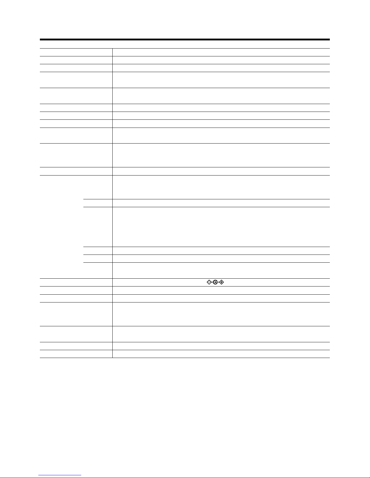
52
Model name/Article name 28A9017 D-ILA multimedia projector
Emission method D-ILA®* (Reflective Active Matrix Principle)
Display panel/ size D-ILA /0.7 (1400pixels x 1050pixels) x 3 (Total number of pixels: 4,410,000)
Projecting lens x 1.3 zoom lens (2.1: ~2.6:1) (Manual zooming and focusing)
Light-source lamp 250W Ultra High Pressure Mercury lamp
[Part No.: BHL5006-S/Rating: 250W]
Screen size 40 ~ 200 / (with aspect ratio: 4:3)
Projection distance Approx. 1.6m ~ 12m
Color system NTSC, NTSC4.43, PAL, SECAM (Automatic switching/manual switching)
Resolution 1400 dots x 1050 dots (S-XGA full resolution, during RGB input)
1000 TV lines (Horizontal resolution, aspect ratio 4:3, during video input)
Scanning frequency Horizontal frequency : 15kHz~120kHz
Vertical frequency : 50Hz~120Hz
Please be sure to refer to the frequency correspondence table on page 20.
Audio Power output: 1W (monaural), 4cm round type micro-speaker x 1
Input terminals VIDEO IN Y/C 1-line, mini DIN 4 pin x 1
Y: 1.0 Vp-p, 75ohm C:0. 286 Vp-p, 75ohm(NTSC), 0.3Vp-p, 75ohm(PAL)
VIDEO 1-line, RCA pin x 1 1.0V(p-p),75ohm,synchronised
PC 1 1-line, D-sub 3-rows 15 pin x 1
PC 2 1-line, BNC x 5
Y, C
B,CR : Component (Y, B-Y, R-Y) signal (Color Difference signal)
Y, P
B, PR : DTV-format (Y, PB, PR) signal
R, G, B : Analog RGB signal
H/Cs, V : Horizontal (H) sync/composite (Cs) sync, Vertical (V) sync signal
PC3 1-line, DVI-D (single-24pin) terminal
AUDIO 1-line, RCApin X 1 (Y/C, VIDEO, PC1, PC2, PC3) 0.5V(rms), high impedance
CONTROL RS-232C : 2-lines, D-sub 9pin x1 (External controller) ❈ (IN : 1 system OUT : 1 system)
REMOTE : 1-line, stereo mini-jack x1 (remote control)
Output terminals DC OUT 5V, 1.5A DC Power Jack
Power requirements AC 100V ~ 240V AC, 50Hz/ 60Hz
Power consumption 3.4 A (100V AC) ~ 1.42A (240V AC)
Operation environment Temperature: 41°F ~ 95°F (+5°C ~ +35°C)
Humidity : 20% ~ 80% (no condensation.)
[Preservation temperature 14°F ~ 140°F (–10°C ~ +60°C)]
Dimensions (Width x Height x Length)
Approx. 121/10”x approx. 53/8”x approx. 141/2” (Approx. 307mm x 136mm x 368mm)
(Excluding handle, foot, lens and protrusion portion)
Mass
Approx. 13.0lbs (Approx. 5.9Kg)
Accessories (☞ page 6)
Specifications
• D-ILA® is the abbreviation for Direct drive Image Light Amplifier.
• Design and Specifications are subject to change without notice.
• D-ILA
®
devices are manufactured using extremely high-precision technology. Pixel effectiveness is 99.99%. Only 0.01% or less of
the pixels would either not lit up or remain permanently lit up.
• Please note that some pictures and illustrations may have been be abridged, enlarged or contextualized in order to aid comprehension. Images may differ from the actual product.
• All brand names and products (IBM, Macintosh) herein are the trademarks or registered trademarks of their respective companies.
• This product conforms to the ‘Household electric appliances and general-purpose articles harmonics control measure guideline’.
Page 53
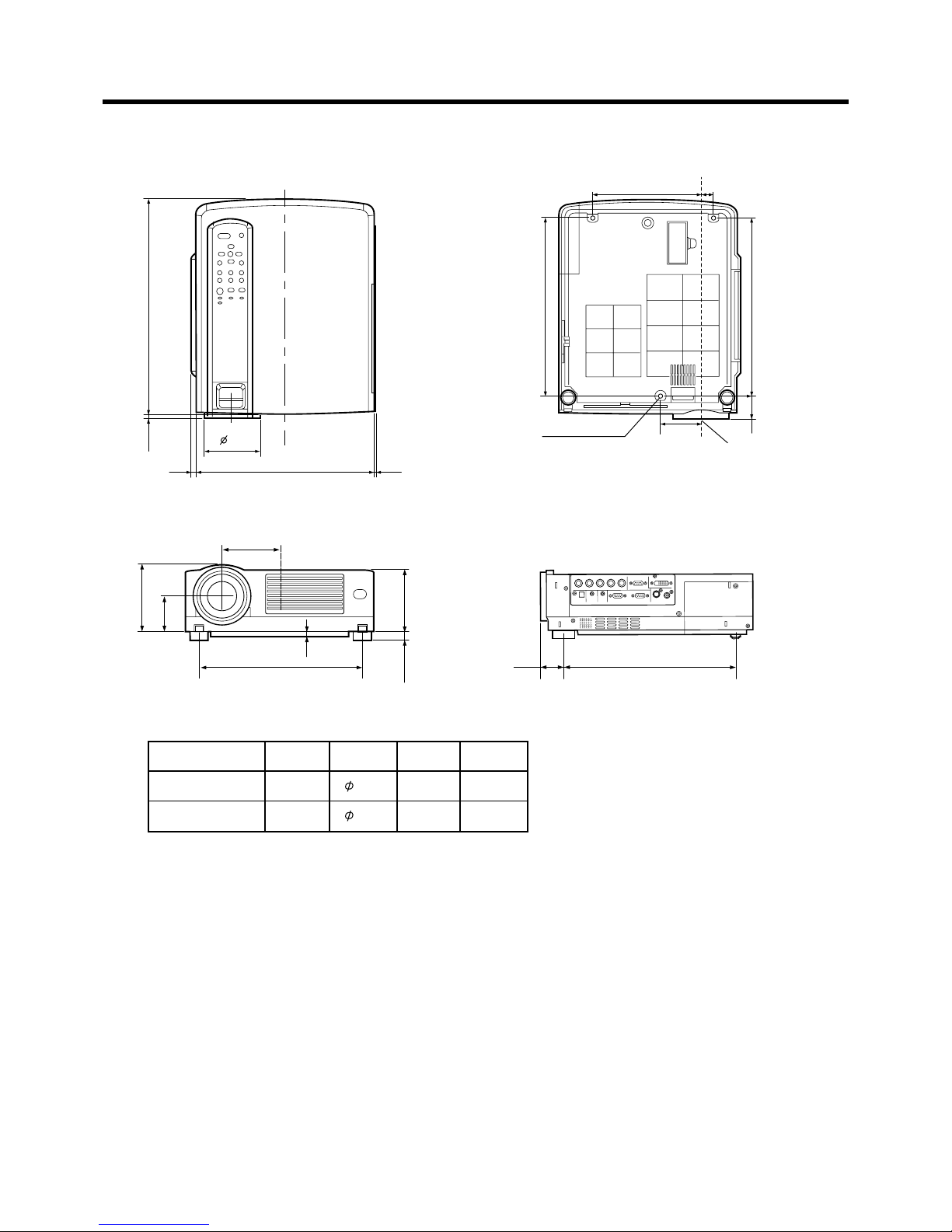
53
Dimensions (unit: mm)
Specifications
6M (Depth 10mm)
Attachment screw should be
more than 6mm but less than 10mm in length.
Center of lens
181 20
67.5
298 27
298
300
360
A
89
267
115.9
65.4
15
20 ~ 56
292
B
L
D
LDAB
8.2 92.5 38.2 36.2
11.0 79.2
41.0 39.0
Front
Bottom Top
Side
Page 54
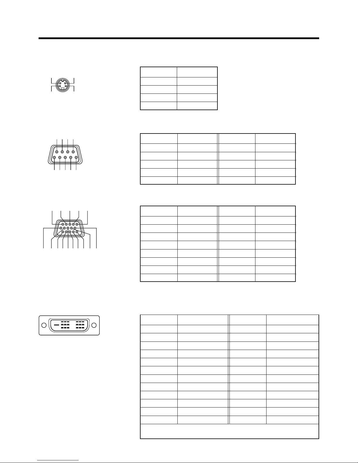
54
4
2
9
8
16
8 7 6
54321
3
1
11 12 13
6712 1094538
1514
24
7
15
23
6
14
22
3
11
19
2
10
18
5
13
21
4
12
20
1
9
17
Specifications
Pin arrangement
Y/C terminal
Pin number Signal name
1 GND (Y)
2 GND (C)
3Y
4C
Pin number Signal name
1N/C
2RD
3TD
4N/C
5 GND
Pin number Signal name
6N/C
7N/C
8N/C
9N/C
RS-232C IN/OUT terminal
PC 1 terminal
PC 3 terminal
Pin number Signal name
1 Red
2Green
3Blue
4N/C
5N/C
6 GND (Red)
7 GND (Green)
8 GND (Blue)
Pin number Signal name
9N/C
10 GND (SYNC)
11 GND
12 N/C
13 H.SYNC
14 V.SYNC
15 N/C
Pin number Signal name
1 TMDS data 2 -
2 TMDS data 2 +
3 TMDS data 2 /4 shield
4N/C
5N/C
6 DDC clock
7 DDC data
8N/C
9 TMDS data 1 -
10 TMDS data 1 +
11 TMDS data 1/3 shield
12 N/C
Pin number Signal name
13 N/C
14 TMDS +5V power supply
15 Earth (+5V)
16 Hot plug detection
17 TMDS data 0 -
18 TMDS data 0+
19 TMDS data 0/5 shield
20 N/C
21 N/C
22 TMDS clock shield
23 TMDS clock +
24 TMDS clock -
TMDS = Transition Minimized Differential Signaling
DDC = Display Data Channel
Page 55
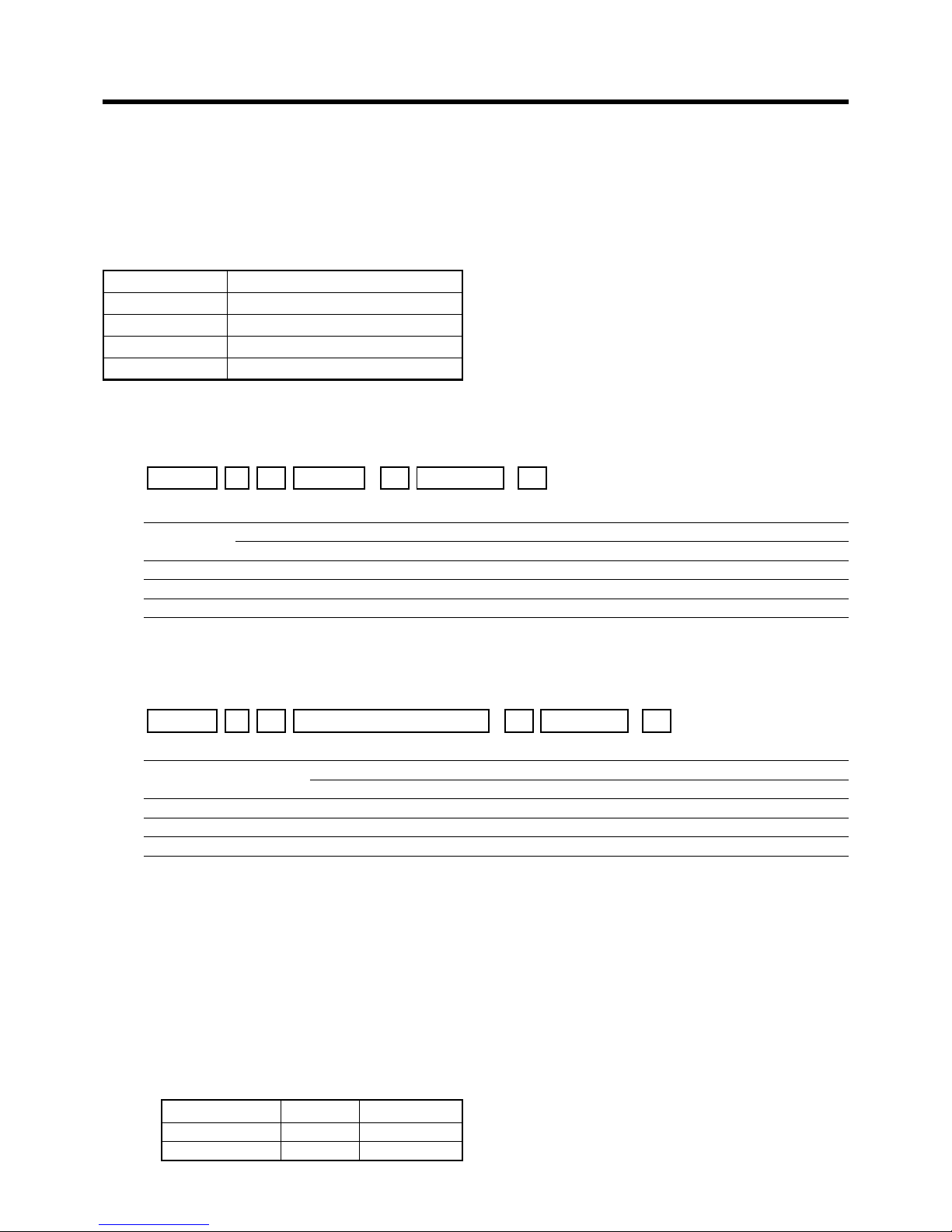
55
Specifications
RS-232C external control
By connecting a computer to the projector with a RS-232C cross cable (D-sub 9 pins), you can control the projector with the
computer. The commands to control the projector and the response data format against the received commands are explained
here.
For details, please consult the authorized dealer where you purchased your projector.
1. Communication Specifications
The communication specifications are as follows.
Baud rate 9600bps/19200bps
Data length 8 bits
Parity None
Stop bit 1 bit
Flow control None
2. Command Format
2-1 Command data format
When sending a control command to the projector, use the following data format.
Header ID
SP
Parameter
Command
SP
CR
[
[
Header : Designates the head of data and the data type.
: ‘!’ (21h): Assigns command to the projector.
: ‘?’ (3Fh): Query to the projector. (Asking command)
ID : ‘1’: The identification number of the projector. (Manufacturer set value ‘1’)
SP : Designates the delimiter for ID, Command, and Parameter. (20h)
CR : Designates the terminal of the data. (0Dh)
* [ ] is not necessary for Asking command.
2-2 Response data format
Upon executing a control command it has received, the projector sends back the following response data to the computer:
Header ID
SP
Parameter
Normal Termination Status
SP
CR
[
[
Header : Designates the head of data.
: ‘@’ (40h): Fetches data from the projector.
ID : ‘1’: The identification number of the projector. (Manufacturer set value”1”)
SP : Designates the delimiter for ID, Command, and Parameter. (20h)
Normal Termination Status : ‘0’ (30h)
CR : Designates the terminal of the data. (0Dh)
2-3 Parameters used for the data format
The following three kinds of parameters are used for control commands and response data.
1) Numeric value
2) ON/OFF
3) Special parameters
Each parameter is as follows:
1) Numeric value
A 2-byte hexadecimal value (sign included) is represented by a set of 4 digit (4 bytes) characters.
Designated range: ‘8000’ to ‘7FFF’.
2) ON/OFF
Shows the status (ON/OFF) of the projector, such as POWER and HIDE.
Character Hex. Meaning
‘0’ 30 OFF
‘1’ 31 ON
Page 56
56
Specifications
3) Special parameters
Input switching parameters
Character Hex. Meaning
‘0’ 30 Y/C
‘1’ 31 VIDEO
‘3’ 33 PC1
‘4’ 34 PC2
‘5’ 35 PC3
Operation mode parameters
Character Hex. Meaning
‘0000’ 30h 30h 30h 30h Stand-by mode
‘0001’ 30h 30h 30h 31h Power-on mode
‘0002’ 30h 30h 30h 32h Cool-down mode
‘0004’ 30h 30h 30h 34h Emergency mode
Function Command
Asking Data type
Power on ELSE
Numeric Value
ON/OFF Special Data
OPERATE U0F X X X
嘷
X
HIDE U00
嘷
XX
嘷
X
Right Left reversal
U17
嘷
XX
嘷
X
Top Bottom inversion
U18
嘷
XX
嘷
X
Input switch U1A
嘷
XX X Y/C ...
Operation mode
Z03
嘷嘷
XXStand-by…
Operation mode: Only Asking command is possible.
3. External control command table
Page 57

LEGAL INFORMATION
FIVE-YEAR LIMITED WARRANTY
This Dukane LCD projector is warranted to the original purchaser for a period of
five (5) years from the original purchase date - in normal use and service against defects in material and workmanship. DUKANE CORPORATION
EXPRESSLY DISCLAIMS ALL OTHER WARRANTIES OF MERCHANTABILITY
AND FITNESS FOR A PARTICULAR PURPOSE.
During the warranty period, Dukane Corporation will repair or replace (at the
manufacturer's option) any such defective parts (except for the lamp, which is
subject to whatever warranties the manufacturer may provide) without charge to
the purchaser for parts or labor when the product is returned, prepaid and insured,
with proof-of-purchase date. This remedy is void if the product has been
damaged by accident, unreasonable use, neglect, improper service or other
causes not arising out of defects in material or workmanship.
Dukane Corporation disclaims all liability for incidental or consequential damage
of any kind, including all damages arising out of any interruptions in operation of
the product and all damages to software.
No person, firm, or representative is authorized to assume any obligation or to
make any warranty on behalf of the Dukane Corporation other than as stated
above.
THIS LIMITED WARRANTY IS VALID FOR U.S.A AND CANADA.
FOR OTHER LOCATIONS, LOCAL WARRANTIES APPLY.
SERVICE & REPAIR
For service and parts, contact the Dukane AV Service Department
at 1 (800) 676-2487 within the USA or 1 (630) 584-2300 worldwide.
If you would like to send a facsimile (FAX), dial 1 (630) 584-5156 worldwide.
When requesting warranty service, please have the sales receipt available along
with the model name and serial number.
If it becomes necessary to return the projector, use the original packing material
and box (if retained) or pack securely. Dukane Corporation will not be liable for
any pick-up or delivery charges or any expenses incurred for service calls or
service supplied by anyone other than the Dukane AV Service Department.
Page 58

Audio Visual Products
Dukane Corporation
Audio Visual Products Division
2900 Dukane Drive
St. Charles, IL 60174-3395
E-mail: [email protected]
Phone: (630) 762-4040
Orders: (800) 676-2485
Information: (800) 676-2486
Fax: (630) 584-5156
Parts & Service: (800) 676-2487
Fax: (630) 584-0984
Part # 401-602-00
 Loading...