

Page 1
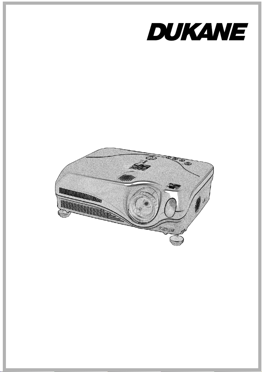
LCD Projector
Model 8915
User's Manual
Page 2

Page 3
Projector
User's Manual - Safety Guide
Thank you for purchasing this projector.
WARNING • Before using, read these user's manuals of this projector to ensure
correct usage through understanding. After reading, store them in a safe place for
future reference. Incorrect handling of this product could possibly result in personal injury
or physical damage. The manufacturer assumes no responsibility for any damage caused by
mishandling that is beyond normal usage defined in these manuals of this projector.
NOTE
• The manufacturer assumes no responsibility for any errors that may appear in this
manual
• The reproduction, transmission or use of this document or contents is not permitted
without express written authority.
• The information in this manual is subject to change without notice.
About The Symbols
Various symbols are used in this manual, the user’s manual and on the product itself to
ensure correct usage, to prevent danger to the user and others, and to prevent property
damage. The meanings of these symbols are described below. It is important that you
read these descriptions thoroughly and fully understand the contents.
This symbol indicates information that, if ignored, could
WARNING
CAUTION
Typical Symbols
This symbol indicates an additional warning (including cautions). An illustration is
provided to clarify the contents.
possibly result in personal injury or even death due to
incorrect handling.
This symbol indicates information that, if ignored, could
result possibly in personal injury or physical damage due to
incorrect handling.
This symbol indicates a prohibited action. The contents will be clearly indicated
in an illustration or nearby (the symbol to the left indicates that disassembly is
prohibited).
This symbol indicates a compulsory action. The contents will be clearly
indicated in an illustration or nearby (the symbol to the left indicates that the
power plug should be disconnected from the power outlet).
1
Page 4

Safety Precautions
WARNING
Never use the projector if a problem should occur.
Abnormal operations such as smoke, strange odor, no image, no sound,
excessive sound, damaged casing or elements or cables, penetration of
liquids or foreign matter, etc. can cause a fire or electrical shock.
In such case, immediately turn off the power switch and then disconnect the
power plug from the power outlet. After making sure that the smoke or odor
has stopped, contact your dealer. Never attempt to make repairs yourself
because this could be dangerous.
• The power outlet should be close to the projector and easily accessible.
Use special caution for children and pets.
Incorrect handling could result in fire, electrical shock, injury, burn or
vision problem.
Use special caution in households where children and pets are present.
Do not insert liquids or foreign object.
Penetration of liquids or foreign objects could result in fire or electrical
shock. Use special caution in households where children are present.
If liquids or foreign object should enter the projector, immediately turn off
the power switch, disconnect the power plug from the power outlet and
contact your dealer.
• Do not place the projector in a bathroom.
• Do not expose the projector to rain or moisture.
• Do not place flower vases, pots, cups, cosmetics, liquids such as water, etc
on or around the projector.
• Do not place metals, combustibles, etc on or around the projector.
• To avoid penetration of foreign objects, do not put the projector into a case
or bag together with any thing except the accessories of the projector,
signal cables and connectors.
Never disassemble and modify.
The projector contains high voltage components. Modification and/or disassembly
of the projector or accessories could result in fire or electrical shock.
• Never open the cabinet.
• Ask your dealer to repair and clean insider.
Do not give the projector any shock or impact.
If the projector should be shocked and/or broken, it could result in an injury,
and continued use could result in fire or electrical shock.
If the projector is shocked, immediately turn off the power switch,
disconnect the power plug from the power outlet and contact your dealer.
Do not place the projector on an unstable surface.
If the projector should be dropped and/or broken, it could result in an injury,
and continued use could result in fire or electrical shock.
• Do not place the projector on an unstable, slant or vibrant surface such as
a wobbly or inclined stand.
• Use the caster brakes placing the projector on a stand with casters.
• Do not place the projector in the side up position, the lens up position or
the lens down position.
• In the case of a ceiling installation or the like, contact your dealer before
installation.
2
Disconnect the
plug from the
power outlet.
Do not
disassemble.
Page 5

Safety Precautions (continued)
WARNING
Be cautious of High temperatures of the projector.
High temperatures are generated when the lamp is lit. It could result in fire
or burn. Use special caution in households where children are present.
Do not touch about the lens, air fans and ventilation openings during use or
immediately after use, to prevent a burn. Take care of ventilation.
• Keep a space of 30 cm or more between the sides and other objects such
as walls.
• Do not place the projector on a metallic table or anything weak in heat.
• Do not place anything about the lens, air fans and ventilation openings of
the projector.
• Do not use with the ventilation opening facing downwards.
• Never block the air fan and ventilation openings.
• Do not cover the projector with a tablecloth, etc.
• Do not place the projector on a carpet or bedding.
Never look through the lens or openings when the lamp is on.
The powerful light could adversely affect vision.
Use special caution in households where children are present.
Use only the correct power cord and the correct power outlet.
Incorrect power supply could result in fire or electrical shock.
• Use only the correct power outlet depending on the indication on the
projector and the safety standard.
• The enclosed power cord must be used depending on the power outlet to
be used.
Be cautious of the power cord connection.
Incorrect connection of the power cord could result in fire or electrical
shock.
• Do not touch the power cord with a wet hand.
• Check that the connecting portion of the power cord is clean (with no
dust), before using. Use a soft and dry cloth to clean the power plug.
• Insert the power plug into a power outlet firmly. Avoid using a loose,
unsound outlet or contact failure.
Be sure to connect with ground wire.
Connect the ground terminal of AC inlet of this unit with the ground
terminal provided at the building using the correct power cord; otherwise,
fire or electric shock can result.
• Don’t take the core of power cord away.
Surely connect
the ground wire.
3
Page 6
Safety Precautions (continued)
WARNING
Be careful in handling the light source lamp.
The projector uses a high-pressure mercury glass lamp made of glass. The
lamp can break with a loud bang, or burn out. When the bulb bursts, it is
possible for shards of glass to fly into the lamp housing, and for gas
containing mercury to escape from the projector’s vent holes.
Please carefully read the section “Lamp”.
Be careful in handling the power cord and external connection cables.
If you keep using a damaged the power cord or cables, it can cause a fire or
electrical shock. Do not apply too much heat, pressure or tension to the
power cord and cables.
If the power cord or cables is damaged (exposed or broken core wires, etc.),
contact your dealer.
• Do not place the projector or heavy objects on the power cord and cables.
Also, do not place a spread, cover, etc, over them because this could result
in the inadvertent placing of heavy objects on the concealed power cord or
cables.
• Do not pull the power cord and cables. When connecting and
disconnecting the power cord or cables, do it with your hand holding the
plug or connector.
• Do not place the cord near the heater.
• Avoid bending the power cord sharply.
• Do not attempt to work on the power cord.
Be careful in handling the battery of the remote control.
Incorrect handling of the battery could result in fire or personal injury. The
battery may explode if not handled properly.
• Keep the battery away from children and pets. If swallowed consult a
physician immediately for emergency treatment.
• Do not allow the battery in a fire or water.
• Avoid fire or high-temperature environment.
• Do not hold the battery with the metallic tweezers.
• Keep the battery in a dark, cool and dry play.
• Do not short circuit the battery.
• Do not recharge, disassemble or solder the battery.
• Do not give the battery a physical impact.
• Use only the battery specified in the other manual of this projector.
• Make sure the plus and minus terminals are correctly aligned when
loading the battery.
• If you observe a leakage of the battery, wipe out the flower and then
replace the battery. If the flower adheres your body or clothes, rinse well
with water.
• Obey the local laws on disposing the battery.
4
Page 7
Safety Precautions (continued)
CAUTION
Be careful in moving the projector.
Neglect could result in an injury or damage.
• Do not move the projector during use. Before moving, disconnect the
power cord and all external connections, and close the slide lens door or
attach the lens cap.
• Avoid any impact or shock to the projector.
• Do not drag the projector.
• For moving the projector, use the enclosed case or bag if provided.
Do not put anything on top of the projector.
Placing anything on the projector could result in loss of balance or falling,
and cause an injury or damage. Use special caution in households where
children are present.
Do not attach anything other than specified things to the projector.
Neglect could result in an injury or damage.
• Some projector has a screw thread in a lens part. Do not attach anything
other than specified options (such as conversion lens) to the screw thread.
Avoid a smoky, humid or dusty place.
Placing the projector in a smoke, a highly humid, dusty place, oily soot or
corrosive gas could result in fire or electrical shock.
• Do not place near the smoking space, the kitchen or a humidifier.
Take care of the air filter to normal ventilate.
The air filter should be cleaned periodically. If the air filter becomes
clogged by dust or the like, internal temperature rises and could cause
malfunction. The projector may display the message such as “CHECK THE
AIR FLOW” or turn off the projector, to prevent the internal heat level
rising.
• When the indicators or a message prompts you to clean the air filter, clean
the air filter as soon as possible.
• If the soiling will not come off the air filter, or it becomes damaged,
replace the air filter.
• Use the air filter of the specified type only. Please order the air filter
specified in the other manual of this projector to your dealer.
• When you replace the lamp, replace also the air filter. The air filter may be
attached when you buy a replacement lamp for this projector.
• Do not turn on the projector without air filter.
Avoid a high temperature environment.
The heat could have adverse influence on the cabinet of the projector and
other parts. Do not place the projector, the remote control and other parts in
direct sunlight or near a hot object such as heater, etc.
Remove the power cord for complete separation.
• For safety purposes, disconnect the power cord if the projector is not to be
used for prolonged periods of time.
• Before cleaning, turn off and unplug the projector. Neglect could result in
fire or electrical shock.
Disconnect the
plug from the
power outlet.
5
Page 8

Safety Precautions (continued)
CAUTION
Ask your dealer to cleaning inside of the projector about every two
years.
Accumulations of dust inside the projector cause result in fire or
malfunction. Cleaning inside is more effective if performed before every
humid periods such as rainy season.
• Do not clean inside yourself because it is dangerous.
NOTE
Do not give the remote control any physical impact.
A physical impact could cause damage or malfunction of the remote control.
• Take care not to drop the remote control.
• Do not place the projector or heavy objects on the remote control.
Take care of the lens.
• Close the slide lens door or attach the lens cap to prevent the lens surface being
scratched when the projector is not used.
• Do not touch the lens to prevent fog or dirt of the lens that cause deterioration of display
quality.
• Use commercially available lens tissue to clean the lens (used to clean cameras,
eyeglasses, etc.). Be careful not to scratch the lens with hard objects.
Take care of the cabinet and the remote control.
Incorrect care could have adverse influence such as discoloration, peeling paint, etc.
• Use a soft cloth to clean the cabinet and control panel of the projector and the remote
control. When excessively soiled dilute a neutral detergent in water, wet and wring out the
soft cloth and afterward wipe with a dry soft cloth. Do not use undiluted detergent
directly.
• Do not use an aerosol sprays, solvents, volatile substances or abrasive cleaner.
• Before using chemical wipes, be sure to read and observe the instructions.
• Do not allow long-term close contact with rubber or vinyl.
About bright spots or dark spots.
Although bright spots or dark spots may appear on the screen, this is a unique characteristic of
liquid crystal displays, and such do not constitute or imply a machine defect.
Be careful of printing of the LCD panel.
If the projector continues projecting a still image, inactive images or 16:9 aspect images
in case of 4:3 panel, etc., for long time, the LCD panel might possibly be printed.
In such a case, please make the projector project a whole white screen for 1 hour or more.
You can use the BLANK function of the projector.
About consumables.
Lamp, LCD panels, polarizors and other optical components, and air filter and cooling
fans have a different lifetime in each. These parts may need to be replaced after a long
usage time, even if one year has not passed since the beginning of using. For more details,
please consult your dealer.
6
Page 9

Safety Precautions (continued)
NOTE
Avoid strong rays.
Any strong ray (such as direct rays of the sun or room lighting) onto the remote control
sensors could invalidate the remote control.
Avoid radio interference.
Any interfering radiation could cause disordered image or noises.
• Avoid radio generator such as a mobile telephone, transceiver, etc. around the projector.
About displaying characteristic.
The display condition of the projector (such as color, contrast, etc.) depends on
characteristic of the screen, because the projector uses a liquid crystal display panel. The
display condition can differ from the display of CRT.
• Do not use a polarized screen. It can cause red image.
Turn the power on/off in right order.
To prevent any trouble, turn on/off the projector in right order mentioned below unless
specifying.
• Power on the projector before the computer or video tape recorder.
• Power off the projector after the computer or video tape recorder.
Take care not to fatigue your eyes.
Rest the eyes periodically.
Set the sound volume at a suitable level to avoid bothering other people.
• It is better to keep the volume level low and close the windows at night to protect the
neighborhood environment.
Connecting with notebook computer
When connecting with notebook computer, set to valid the RGB external image output
(setting CRT display or simultaneous display of LCD and CRT).
Please read instruction manual of the notebook for more information.
7
Page 10

Lamp
WARNING
The projector uses a high-pressure mercury glass lamp. The lamp can break with a
loud bang, or burn out, if jolted or scratched, handled while hot, or worn over time.
Note that each lamp has a different lifetime, and some may burst or burn out soon after
you start using them. In addition, when the bulb bursts, it is possible for shards of
glass to fly into the lamp housing, and for gas containing mercury to escape from the
projector’s vent holes.
About disposal of a lamp • This product contains a mercury lamp; do not put in trash.
Dispose of in accord with environmental laws.
For lamp recycling, go to www.lamprecycle.org. (in USA)
For product disposal, contact your local government agency or www.eiae.org (in the
US) or www.epsc.ca (in Canada).
For more information, call your dealer.
• If the lamp should break (it will make a loud bang when it does), unplug
the power cord from the outlet, and make sure to request a replacement
lamp from your local dealer. Note that shards of glass could damage the
projector’s internals, or cause injury during handling, so please do not try
to clean the projector or replace the lamp yourself.
Disconnect the
plug from the
power outlet
• If the lamp should break (it will make a loud bang when it does),
ventilate the room well, and make sure not to breathe the gas that comes
out of the projector vents, or get it in your eyes or mouth.
• Before replacing the lamp, make sure the power switch is off and the
power cable is not plugged in, then wait at least 45 minutes for the lamp
to cool sufficiently. Handling the lamp while hot can cause burns, as well
as damaging the lamp.
HIGH VOLTAGE HIGH TEMPERATURE HIGH PRESSURE
• Do not open the lamp cover while the projector is suspended from above.
This is dangerous, since if the lamp’s bulb has broken, the shards will
fall out when the cover is opened. In addition, working in high places is
dangerous, so ask your local dealer to have the lamp replaced even if the
bulb is not broken.
• Do not use the projector with the lamp cover removed. At the lamp
replacing, make sure that the screws are screwed in firmly. Loose screws
could result in damage or injury.
• Use the lamp of the specified type only.
• If the lamp breaks soon after the first time it is used, it is possible that
there are electrical problems elsewhere besides the lamp. If this happens,
contact your local dealer or a service representative.
• Handle with care: jolting or scratching could cause the lamp bulb to burst
during use.
• If the indicators or a message prompts you to replace the lamp (see the
section “Related Messages” and “Regarding the indicator Lamps”),
replace the lamp as soon as possible. Using the lamp for long periods of
time, or past the replacement date, could cause it to burst. Do not use old
(used) lamps; this is a cause of breakage.
8
Page 11

Regulatory Notices
FCC Statement Warning
WARNING: This equipment has been tested and found to comply with the limits for a
Class B digital device, pursuant to Part 15 of the FCC Rules. These limits are designed to
provide reasonable protection against harmful interference in a residential installation.
This equipment generates, uses, and can radiate radio frequency energy and, if not
installed and used in accordance with the instructions, may cause harmful interference to
radio communications. However, there is no guarantee that interference will not occur in a
particular installation. If this equipment does cause harmful interference to radio or
television reception, which can be determined by turning the equipment off and on, the
user is encouraged to try to correct the interference by one or more of the following
measures:
- Reorient or relocate the receiving antenna.
- Increase the separation between the equipment and receiver.
- Connect the equipment into an outlet on a circuit different from that to which the
receiver is connected.
- Consult the dealer or an experienced radio/TV technician for help.
INSTRUCTIONS TO USERS: This equipment complies with the requirements of FCC
(Federal Communication Commission) equipment provided that the following conditions
are met. Some cables have to be used with the core set. Use the accessory cable or a
designated-type cable for the connection. For cables that have a core only at one end,
connect the core to the projector.
CAUTION: Changes or modifications not expressly approved by the party responsible
for compliance could void the user’s authority to operate the equipment.
For the Customers in CANADA
NOTICE: This Class B digital apparatus complies with Canadian ICES-003.
Warranty And After-Service
Unless seen any abnormal operations (mentioned with the first paragraph of WARNING
in this manual), when a problem occurs with the equipment, first refer to the
“Troubleshooting” section of the “User’s manual – Operating Guide”, and run through the
suggested checks.
If this does not resolve the problem contact your dealer or service company. They will tell
you what warranty condition is applied.
9
Page 12

Page 13

Projector
ImagePro
8915
User Manual – Operating Guide
Thank you for purchasing this projector.
WARNING ►Before using, read the "User's Manual - Safety Guide" and
these manuals to ensure correct usage through understanding. After reading,
store them in a safe place for future reference.
About this manual
Various symbols are used in this manual. The meanings of these symbols are
described below.
WARNING This symbol indicates information that , if ignored, could possibly
result in personal injury or even death due to incorrect handling.
CAUTION This symbol indicates information that , if ignored, could result
possibly in personal injury or physical damage due to incorrect
handling.
Please refer to the pages written following this symbol.
NOTE • The information in this manual is subject to change without notice.
• The manufacturer assumes no responsibility for any errors that may appear in this manual.
• The reproductiob, transmission or use of this document or contents is not permitted without
express written authority.
Trademark acknowledgment
• VGA and XGA are registered trademarks of the International Business Machines
Corporation.
• Apple and Mac are registered trademarks of the Apple Computer, Inc.
• VESA and SVGA are trademarks of the Video Electronics Standard Association.
• Windows is a registered trademark of the Microsoft Corporation.
• Internet Explorer is a trademark of the Microsoft Corporation.
• Netscape is a registered trademark of the Netscape Communications Corporation.
All other trademarks are the property of their respective owners.
1
Page 14

2
Contents
Contents
About this manual . . . . . . . . . . 1
Contents . . . . . . . . . . . . . . . . . 2
Projector features . . . . . . . . . .
Preparations . . . . . . . . . . . . . .
About contents of package . . . . . . . 3
Fastening the lens cap . . . . . . . . . . 3
Part names
. . . . . . . . . . . . . . . 4
Projector . . . . . . . . . . . . . . . . . . . . . 4
Control buttons . . . . . . . . . . . . . . . . 5
Remote control . . . . . . . . . . . . . . . . 5
Setting up . . . . . . . . . . . . . . . . 6
Arrangement . . . . . . . . . . . . . . . . . . 7
Adjusting the projector's elevator . . 8
About the filter cover for bottom-up use
Connecting your devices . . . . . . . . 10
Connecting power supply . . . . . . . 13
Remote control . . . . . . . . . . .
Laser pointer . . . . . . . . . . . . . . . . . 14
Putting batteries . . . . . . . . . . . . . . 14
Using the remote control . . . . . . . . 15
Power on/off
. . . . . . . . . . . . . 16
Turning on the power . . . . . . . . . . .
Turning off the power . . . . . . . . . . .
Operating
. . . . . . . . . . . . . . . 17
Adjusting the volume . . . . . . . . . . . 17
Temporarily muting the sound . . . .
Selecting an input signal . . . . . . . . 17
Adjusting screen with ONE-TOUCH
Selecting an aspect ratio . . . . . . . . 18
Adjusting the zoom and focus . . . . 18
Using the automatic adjustment feature
Adjusting the position . . . . . . . . . . 19
Correcting the keystone distortions 20
Using the magnify feature . . . . . . . 20
Freezing the screen . . . . . . . . . . . . 21
Temporarily blanking the screen
Operating the computer screen . . . 22
Multifunctional settings . . . . 23
Using the menu function . . . . . . . . 23
3
3
. . 9
14
16
16
17
. . 18
. 19
. . 21
EASY Menu . . . . . . . . . . . . . . . . . . 24
Aspect, Mode, Bright, Contrast, Color,
Tint, Sharpness, Whisper, Mirror, Reset,
Filter time, Language, Go to advanced
menu
PICTURE Menu . . . . . . . . . . . . . . . 26
Bright, Contrast, Gamma, Color temp,
Color, Tint, Sharpness, My memory
IMAGE Menu . . . . . . . . . . . . . . . . . 29
Aspect, Over scan, V. position, H. phase,
H. position, H. size, Auto adjust execute
VIDEO Qlty. Menu . . . . . . . . . . . . . 31
Progressive, 3D-YCS, Video NR
INPUT Menu . . . . . . . . . . . . . . . . . 32
Color space, Component, Video format,
DVI, Information
SETUP Menu . . . . . . . . . . . . . . . . . 34
Whisper, Mirror, Volume, Stereo, IR remote
SCREEN Menu . . . . . . . . . . . . . . . 35
Language, Menu position, OSD bright,
Blank, Start up, MyScreen,
MyScreen lock, Message
OPTION Menu . . . . . . . . . . . . . . . . 38
One touch, Auto
time, Filter time, Service
search, Auto off, Lamp
NETWORK Menu . . . . . . . . . . . . . 40
DHCP, IP address, Subnet mask, Default
gateway, Information
Maintenance . . . . . . . . . . . . . 44
Lamp . . . . . . . . . . . . . . . . . . . . . . . 44
Air filter
. . . . . . . . . . . . . . . . . . . . . 46
Other care . . . . . . . . . . . . . . . . . . . 47
Troubleshooting
. . . . . . . . . . 48
Related messages . . . . . . . . . . . . . 48
Regarding the indicator lamps . . . . 50
Phenomena that may easily be
mistaken for machine defects . . . . 52
Warranty and after-service
Specifications . . . . . . . . . . . .
. . . 54
54
Technical (English only)
(Please see the end of this book, although only in English.)
Page 15

Projector features / Preparations
Projector features
This projector is used to project various computer signals as well as NTSC/PAL/
SECAM video signals onto a screen. It requires just a little space for installation
and gets a large image from short distance.
High Brightness
Newly developed 230W UHB (Ultra High Brightness) lamp gives you a higher
brightness image on a screen. The image can be still kept as bright and clean
enough for use in bright rooms.
Low Noise
WHISPER mode is equipped for reducing acoustic noise to realize quieter
operation. It is perfect for use in low luminance rooms where low noise is more
important than brightness.
Rich Connectivity
This projector has a variety of I/O ports. It can be easily connected to many
signal sources like PC, DVD and so on. The rich connectivity provides you
more options to make your presentation impressive.
Compact Body
Even with its many features, this projector is extremely compact and slim,
which gives you more flexibility and usability to use it where you want.
Preparations
About contents of package
Please see the "Contents of package" of the "User's Manual - Quick Guide". Your
projector should come with the items shown there. Contact immediately your
dealer if anything is missing.
NOTE
moving the projector, be sure to use the original packing material. Use special
caution for the lens part.
• Keep the original packing materials for future reshipment. For
Fastening the lens cap
To avoid losing, please fasten the lens cap to the projector using the strap.
Strap ring
Strap
Fix the strap to the strap ring of lens cap.
1.
Put the strap into the groove on rivet.
2.
Push the rivet into the strap hole.
3.
Strap hole
Bottom side
3
Page 16
4
Y
VIDEO
RGB IN1 RGB IN2
DVI-
D
RGB OUT CONTROL
AUDIO-IN
REMOTE
CONTRO
L
US
B
DC OU
T
S-VIDE
O
LA
N
COMPONENT VIDE
O
CB/P
B
CR/P
R
R-AUDIO IN-L
AUDIO-OU
T
Part names
Part names
Projector
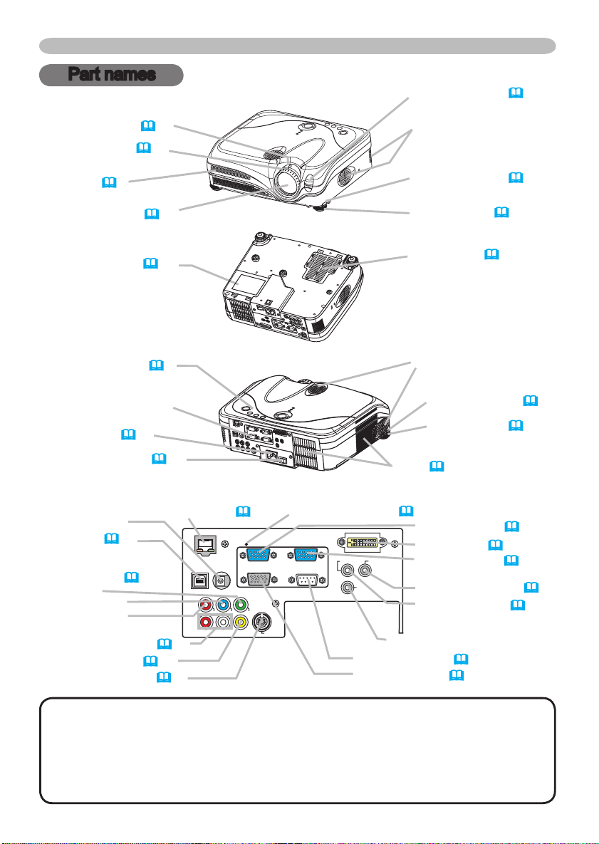
Zoom knob (18)
Focus ring (18)
Remote sensor (15)
Speaker
Vent (
6)
Lens (16)
Lamp cover (45)
(Lamp unit is inside.)
Control buttons (5)
(See the following page.)
Ports (See below.)
AC inlet (13)
Power switch (16)
DC OUT port
USB port (11)
COMPONENT
VIDEO ports (12)
Y
B
CB/P
R
CR/P
Front-Right side
Bottom side
LAN port (
Rear-Left side
Restart switch (*) (52)
)
12
Elevator button (8)
Elevator foot (8)
Filter cover (46)
(Air filter and intake vent
are inside.)
Speaker
Elevator button (8)
Elevator foot (8)
Vent (
6)
RGB IN1 port (
DVI-D port (11)
RGB IN2 port (11)
AUDIO OUT port (11)
AUDIO IN port (11)
)
11
AUDIO IN L/R port (
VIDEO port (12)
S-VIDEO port (12)
12
)
Ports
WIRED REMOTE port
CONTROL port (
RGB OUT port (
11
)
11
NOTE (*) About Restart switch: This Projector is controlled by an internal
microprocessor. Under certain exceptional circumstances, the projector may not
operate correctly and the microprocessor will need to be reset. In such a case,
please push the Restart switch by using a cocktail stick or similar, and before
turning on again, make the projector cool down at least 10 minutes without
operating. Only push the Restart switch in these exceptional instances.
)
Page 17
STANDBY/ON
VIDEO
UP
DOWN
BLANK
ASPECT
PUSH
LASER
INDICATOR
LASER
RGB
ENTER
ON
OFF
ESC
POSITION
MAGNIFY
MUTE
KEYSTONE
FREEZE
ONE TOUCH
AUTO
PA
GE
MENU
RESET
VOLUME
STAND BY/ ON
INP U
T
KEY STON E
RES E
T
MEN U
POW ER
TE MP
LA MP
Part names
Control buttons
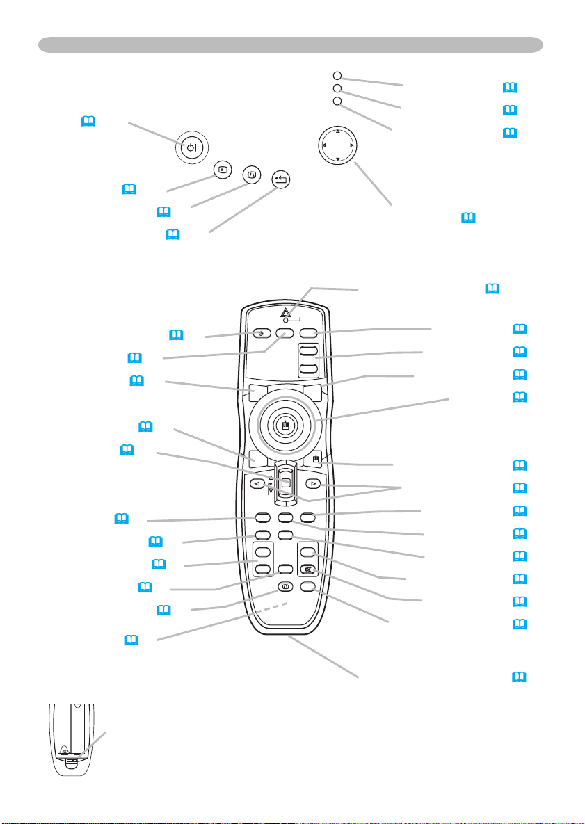
STANDBY/ON
button (16)
INPUT button (
KEYSTONE button (
RESET button (
Remote control
STANDBY/ON button (
VIDEO button (17)
BLANK button (21)
ASPECT button (
Lever switch (23)
Flip toward disk pad: UP key
F
lip toward MENU button: DOWN key
Press in center: ENTER
ESC button (22)
POSITION button (19)
MAGNIFY buttons (
FREEZE button (21)
KEYSTONE button (
Battery cover (14)
(on the back)
17)
20)
23)
16)
18)
20)
20)
Laser switch (Inside of the battery cover)
1: enables the laser function
2: disables the laser function
LAMP incicator (
TEMP indicator (
POWER indicator (16)
Cursor buttons
▲,▼,◄,►(23)
LASER INDICATOR (14)
RGB button (17)
PAGE buttons (
LASER button (14)
Disk pad(22)
Right mouse button (22)
CURSOR buttons (23)
RESET button (
MENU button (23)
AUTO butotn (
VOLUME button (17)
MUTE button (17)
ONE TOUCH button (
REMOTE CONTROL port
50)
50)
(15)
22)
23)
19)
18)
5
Page 18

6
Setting up
Setting up
WARNING ►Place the projector in a stable position horizontally. A fall or
a turnover could cause an injury and/or damage to the projector. Then using
damaged projector could result in a fire and/or an electric shock.
• Don’t place the projector on an unstable, slant or vibrant surface such as a
wobbly or inclined stand.
• Do not place the projector in the side/front/rear-up position, except care of the
air filter.
• For the projector installed bottom-up, use the accessory filter cover for bottom-
up use. And in the case of a ceiling installation or the like, contact your dealer
before installation.
►Place the projection in a cool place, and pay attention enough to ventilation.
The high temperature of the projector could cause a fire, a burn and/or
malfunction to the projector.
• Don’t stop up, block and cover the projector's vents.
• Keep a space of 30 cm or more between the sides and other objects such as
walls.
• Don’t place the projector on a metallic thing or anything weak in heat.
• Don’t place the projector on a carpet, cushion or bedding.
• Don’t place the projector in direct sunlight or near a hot object such as heater.
• Put nothing about lens and vents of the projector. Put nothing on the projector.
• Put nothing that is sucked or sticks to the bottom of projector. This projector
has some intake vents also on the bottom.
►Do not place the projector on the place that gets wet. Damping the projector
or inserting liquid in the projector could cause a fire, an electric shock and/or
malfunction to the projector.
• Don’t place the projector in a bathroom or the outdoors.
• Put nothing containing the liquid near the projector.
CAUTION ►Avoid a smoky, humid or dusty place. Placing the projector
in such place could cause a fire, an electric shock and/or malfunction to the
projector.
• Don’t place the projector near a humidifier, a smoking space or a kitchen.
• Put nothing containing the liquid near the projector.
►Adjist the direction of the projector to keep light from directly hitting the
projector's remote sensor.
Page 19

Setting up
Arrangement
Refer to the illustrations and tables below to determine the screen size and projection
distance.
The values shown in the table are calculated for a full size screen: 1024 x 768
(a) The screen size (diagonal)
(b) Distance from the projector to the screen (±10%)
(c) The height of the screen (±10%)
(b)
4:3
(a)
At 4:3 screen
(a) Screen size
[inch (m)]
30 (0.8) 0.9 (35) 1.1 (42)
40 (1.0) 1.2 (47) 1.4 (57) 6 (2) 55 (22)
50 (1.3) 1.5 (59) 1.8 (71) 8 (3) 69 (27)
60 (1.5) 1.8 (71) 2.2 (86) 9 (4) 82 (32)
70 (1.8) 2.1 (83) 2.6 (100) 11 (4) 96 (38)
80 (2.0) 2.4 (96) 2.9 (115) 12 (5) 110 (43)
90 (2.3) 2.7 (108) 3.3 (130) 14 (5) 123 (49)
100 (2.5) 3.0 (120) 3.7 (144) 15 (6) 137 (54)
120 (3.0) 3.7 (144) 4.4 (174) 18 (7) 165 (65)
150 (3.8) 4.6 (181) 5.5 (217) 23 (9) 206 (81)
200 (5.1) 6.1 (241) 7.4 (291) 30 (12) 274 (108)
250 (6.4) 7.7 (302) 9.2 (364) 38 (15) 343 (135)
300 (7.6) 9.2 (363) 11.1 (437) 46 (18) 411 (162)
At 16:9 screen
(a) Screen size
[inch (m)]
30 (0.8) 1.0 (38) 1.2 (46)
40 (1.0) 1.3 (51) 1.6 (62) -2 (-1) 51 (20)
50 (1.3) 1.6 (65) 2.0 (78) -2 (-1) 64 (25)
60 (1.5) 2.0 (78) 2.4 (94) -2 (-1) 77 (30)
70 (1.8) 2.3 (91) 2.8 (110) -3 (-1) 90 (35)
80 (2.0) 2.6 (104) 3.2 (126) -3 (-1) 103 (41)
90 (2.3) 3.0 (117) 3.6 (141) -4 (-1) 116 (46)
100 (2.5) 3.3 (131) 4.0 (157) -4 (-2) 129 (51)
120 (3.0) 4.0 (157) 4.8 (189) -5 (-2) 154 (61)
150 (3.8) 5.0 (197) 6.0 (237) -6 (-2) 193 (76)
200 (5.1) 6.7 (263) 8.0 (317) -8 (-3) 257 (101)
250 (6.4) 8.4 (329) 10.1 (396) -10 (-4) 322 (127)
300 (7.6) 10.0 (395) 12.1 (476) -12 (-5) 386 (152)
16:9
(c) up
(a)
(c) down
(b) Projection distance [m (inch)] (c) Screen height [cm (inch)]
min. max. down up
5 (2) 41 (16)
(b) Projection distance [m (inch)] (c) Screen height [cm (inch)]
min. max. down up
-1 (0) 39 (15)
7
Page 20

8
Setting up
Adjusting the projector's elevator
WARNING ►Do not adjust the projector’s elevator during use or
immediately after use. Handling while the projector is in a high temperature
could cause a burn and/or malfunction to the projector.
CAUTION ►If you press the elevator button without holding the projector,
the projector might crash down, overturn, smash your fingers and possibly
result in malfunction. To prevent damaging the projector and injuring yourself,
always hold the projector whenever using the elevator buttons to adjust the
elevator feet.
►Except for inclining by the elevator feet adjustment, place the projector
horizontally.
You can use the elevator feet to make adjustments if the surface on which you
need to set the projector is uneven or if you otherwise need to adjust the angle of
projection. The adjustment range of the elevator feet is 0 to 9 degrees.
Elevator feet
After making sure that the projector is cool adequately, press and hold in the
1.
elevator buttons while holding the projector.
The elevator buttons and the elevator feet are on the both sides.
Raise or lower the projector to the desired height and the release the elevator
2.
buttons.
When you release the elevator buttons, the elevator feet will lock into position.
As necessary, you can also finely adjust the height of the projector by twisting
3.
the elevator feet by hand.
Elevator button
Page 21

Setting up
About the filter cover for bottom-up use
WARNING ►Do not replace the filter cover during use or immediately
after use. While the projector connects with a power supply, or the projector is
in a high temperature state, handling could cause an electric shock, a fire, a
burn and/or malfunction to the projector.Before handling, make sure the power
switch is off and the power cord is not plugged in, then wait at least 45 minutes.
When the projector is installed bottom up, please use the accessory filter cover
for bottom-up use. It is higher than usual filter cover, to keep the space for intake
ventilation. Please change in the following procedure.
Filter cover’s claws
To remove
Filter cover
After making sure that the projector is cool adequately, slowly turn the
1.
projector so that the lens-side is facing up. Please be careful for a projector
not to fall. While the projector is placed lens-side up, hold the projector.
Unhooking the filter cover’s claws, pull the filter cover in the direction of the
2.
arrow to remove it.
Replace the filter cover for bottom-up use and snap it back into place.
3.
Slowly turn the projector so that the top is facing up.
4.
To set
Filter cover for bottom-up use
Filter cover’s claws
9
Page 22

10
Setting up
Connecting your devices
CAUTION ►Turn off all devices prior to connecting them to the projector.
Attempting to connect a live device to the projector may generate extremely
loud noises or other abnormalities that may result in malfunction and/or damage
to the device and/or projector.
►Use the accessory cable or a designated-type cable for the connection.
Some cables have to be used with core set. A too long cable may cause a
certain picture degradation. Please consult with your dealer for details. For
cables that have a core only at one end, connect the core to the projector.
►Make sure that you connect devices to the correct port. Incorrect connection
may result in malfunction and/or damage to the device and/or projector.
NOTE • Whenever attempting to connect a laptop computer to the projector, be sure
to activate the laptop’s RGB external image output (set the laptop to CRT display or to
simultaneous LCD and CRT display). For details on how this is done, please refer
instruction manual of the corresponding laptop computer.
• Secure the screws on the connectors and tighten.
• Some computers may have multiple display screen modes. Use of some of these
modes will not be possible with this projector.
• For some RGB signal modes, the optional Mac adapter is necessary.
• When the image resolution is changed on a computer, depending on an input,
automatic adjust function may take some time and may not be completed. In this case,
you may not be able to see a check box to select “Yes/No” for the new resolution on
Windows. Then the resolution will go back to the original. It might be recommended to
use other CRT or LCD monitors to change the resolution.
About Plug-and-Play capability
Plug-and-Play is a system composed of the computer, its operating system and
peripheral equipment (i.e. display devices). This projector is compatible with VESA DDC
2B. Plug-and-Play can be achieved by connecting this projector to computers that are
VESA DDC (display data channel) compatible.
• Please take advantage of this function by connecting the accessory RGB cable to the
RGB IN1 port (DDC 2B compatible) and/or the optional DVI cable to the DVI-D port (DDC
2B compatible). Plug-and-Play may not work properly if any other type of connection is
attempted.
• Please use the standard drivers in your computer as this projector is a Plug-and-Play
monitor.
• The 8915's DVI is compatible with HDCP (High-bandwidth Digital Content
Protection) and therefore capable of displaying video from HDCP compatible DVD
players, et al. However, if the HDCP standards are modified, the 8915's DVI might
not be able to display video from HDCP compatible device developed in conformance to
such modified HDCP standards.
to the
Page 23
Y
VIDEO
RGB IN1 RGB IN2
DVI-
D
RGB OUT CONTROL
AUDIO-IN
REMOTE
CONTRO
L
US
B
DC OUT
S-VIDEO
LA
N
COMPONENT VIDE
O
CB/P
B
CR/P
R
R-AUDIO IN-L
AUDIO-OUT
Y
VIDEO
RGB IN1 RGB IN2
DVI-
D
RGB OUT CONTROL
AUDIO-IN
REMOTE
CONTRO
L
US
B
DC OU
T
S-VIDEO
LA
N
COMPONENT VIDE
O
CB/P
B
CR/P
R
R-AUDIO IN-L
AUDIO-OU
T
Y
VIDEO
RGB IN1 RGB IN2
DVI-
D
RGB OUT CONTROL
AUDIO-IN
REMOTE
CONTRO
L
USB
DC OUT
S-VIDE
O
LAN
COMPONENT VIDEO
CB/P
B
CR/P
R
R-AUDIO IN-L
AUDIO-OU
T
Y
VIDEO
RGB IN1 RGB IN2
DVI-
D
RGB OUT CONTROL
AUDIO-IN
REMOTE
CONTRO
L
US
B
DC OU
T
S-VIDEO
LAN
COMPONENT VIDE
O
CB/P
B
CR/P
R
R-AUDIO IN-L
AUDIO-OU
T
RGB IN2
RGB OUT
Setting up
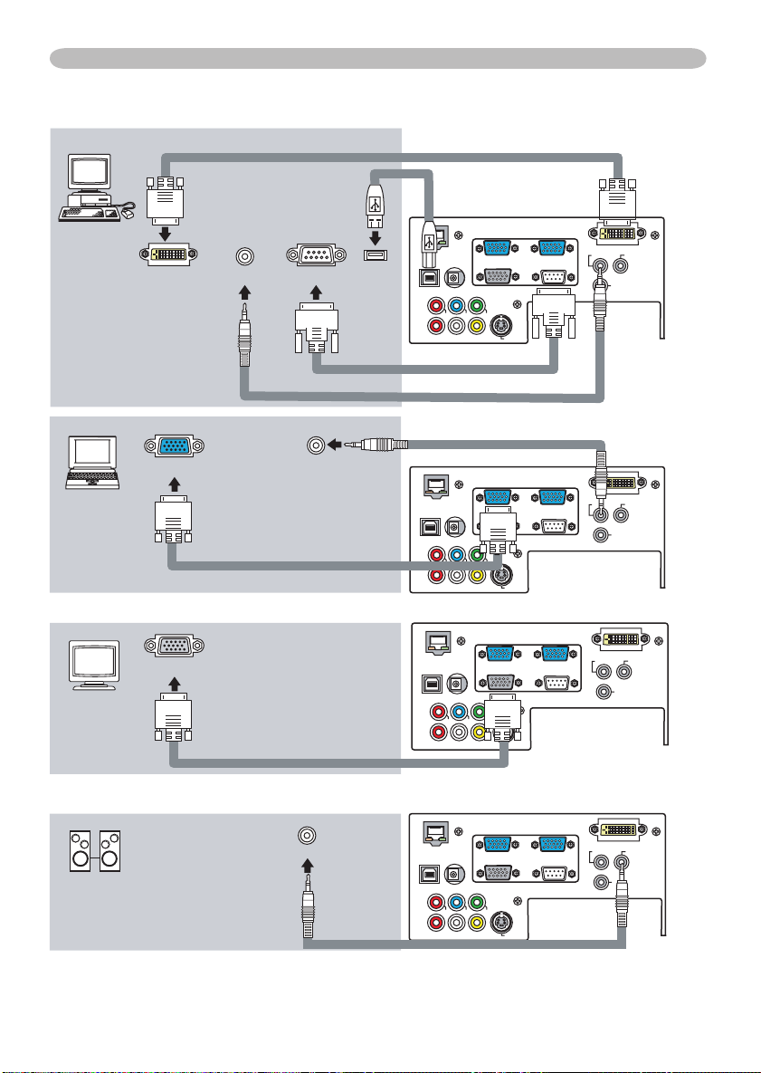
Examples of connection with a computer
DVI out
Audio out
RS-232C
RGB out Audio out
Connecting to a monitor (output)
RGB in
USB(A)
RGB cable
* AUDIO IN is linked to RGB IN1/2
and
DVI-D.
DVI cable
USB cable
RS232C cable
Stereo mini audio cable
Stereo mini audio cable
Connecting to a speaker with amplifier (output)
Audio in
RGB cable
Stereo mini audio cable
11
Page 24

12
Y
VIDEO
RGB IN1 RGB IN2
DVI-D
RGB OUT CONTROL
AUDIO-IN
REMOTE
CONTRO
L
US
B
DC OU
T
S-VIDE
O
LAN
COMPONENT VIDE
O
CB/P
B
CR/P
R
R-AUDIO IN-L
AUDIO-OU
T
Y
VIDEO
RGB IN1 RGB IN2
DVI-D
RGB OUT CONTROL
AUDIO-IN
REMOTE
CONTRO
L
US
B
DC OU
T
S-VIDE
O
LAN
COMPONENT VIDE
O
CB/P
B
CR/P
R
R-AUDIO IN-L
AUDIO-OU
T
Y
VIDEO
RGB IN1 RGB IN2
DVI-
D
RGB OUT CONTRO
L
AUDIO-IN
REMOTE
CONTRO
L
US
B
DC OU
T
S-VIDE
O
LAN
COMPONENT VIDE
O
CB/P
B
CR/P
R
R-AUDIO IN-L
AUDIO-OU
T
Y
VIDEO
RGB IN1 RGB IN2
DVI-
D
RGB OUT CONTRO
L
AUDIO-IN
REMOTE
CONTRO
L
US
B
DC OU
T
S-VIDE
O
LAN
COMPONENT VIDE
O
CB/P
B
CR/P
R
R-AUDIO IN-L
AUDIO-OU
T
Setting up
Examples of connection with a VCR/DVD player
Audio/Video cable
Video out
Audio (L) out
Audio (R) out
S-Video out
Audio (L) out
Audio (R) out
Component video out
Y
CB/P
B
CR/P
R
Audio (L) out
Audio (R) out
S-Video cable
Audio cable
Component video cable
Audio cable
RGB out
LAN port
LAN cable (CAT-5)
Component video out
Y
CB/P
B
CR/P
R
RGB cable
Component video cable
Page 25

Setting up
Connecting power supply
WARNING ►Please use extra caution when connecting the power cord as
incorrect or faulty connections may result in fire and/or electrical shock.
• Only use the power cord that came with the projector. If it is damaged, contact
your dealer to newly get correct one.
• Only plug the power cord into an outlet rated for use with the power cord's
specified voltage range.
• Never modify the power cord. Never attempt to defeat the ground connection
of the three-pronged plug.
Connector
of the power cord
AC inlet
Connect the connector of the power cord to the AC inlet of the projector.
1.
Firmly plug the power cord's plug into the outlet.
2.
13
Page 26
14
Remote control
STANDBY/ON
V
ID
E
O
U
P
DO
W
N
B
L
A
N
K
ASPEC
T
PU
SH
L
A
S
E
R
IN
D
ICAT
O
R
L
A
S
E
R
R
G
B
E
N
T
E
R
O
N
O
F
F
E
SC
POSITION
M
A
G
N
IF
Y
MU
T
E
KEYST
ONE
FREEZ
E
ONE TOUCH
A
UT
O
PA
G
E
M
E
N
U
R
E
S
E
T
V
O
L
UM
E
Remote control
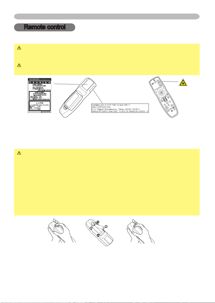
Laser pointer
WARNING ►The laser pointer of the remote control is used in place of a
finger or rod. Never look directly into the laser beam outlet or point the laser
beam at other people. The laser beam can cause vision problems.
CAUTION ►Use of controls or adjustments or performance of procedures
other than those specified herein may result in hazardous radiation exposure.
This remote control has a laser pointer in place of a finger or rod. The laser beam works
and theLASER INDICATOR lights while the LASER button is pressed.
Putting batteries
WARNING ►Always handle the batteries with care and use them only as
directed. Improper use may result in battery explosion, cracking or leakage,
which could result in fire, injury and/or pollution of the surrounding environment.
• Be sure to use only the batteries specified. Do not use batteries of different
types at the same time. Do not mix a new battery with used one.
Make sure the plus and minus terminals are correctly aligned when loading a battery.
•
• Keep a battery away from children and pets.
• Do not recharge, short circuit, solder or disassemble a battery.
Do not allow a battery in a fire or water. Keep batteries in a dark, cool and dry place.
•
•
If you observe a leakage of a battery, wipe out the flower and then replace a battery.
If the flower adheres your body or clothes, rinse well with water immediately.
Remove the battery cover.
1.
Slide back and remove the battery cover in the direction of the arrow.
I
nsert the batteries.
2.
Align and insert the two AA batteries according to their plus and minus
terminals as indicated in the remote control.
Close the battery cover.
3.
Replace the battery cover in the direction of the arrow and snap it back into place.
Page 27
Remote control
Using the remote control
CAUTION ►Be careful in handling the remote control.
• Do not drop or otherwise expose the remote control to physical impact.
• Do not get the remote control wet or place it on wet objects. Doing so may
result in malfunction.
• Remove the batteries from the remote control and store them in a safe place if
you won’t be using the remote control for an extended period.
• Replace the batteries whenever the remote control starts to malfunction.
• When strong lights, such as direct sunlight or light from an extremely close
range (such as from an inverter fluorescent lamp), hit the projector’s remote
sensor, the remote control may cause to function. Adjust the direction of the
projector to keep light from directly hitting the projector’s remote sensor.
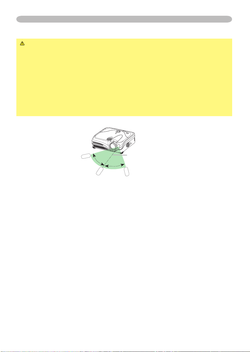
The remote control works with the projector’s remote sensor.
30º
approx. 3 meters
30º
• The range of the remote sensor is 3 meters with a 60- degree range (30 degrees
to the left and right of the remote sensor).
• Also a remote signal reflected in the screen etc. may be available. If it is difficult
to send a remote signal to the sensor directly, please try.
• Since the remote control uses infrared light to send signals to the projector
(Class1 LED), be sure to use the remote control in an area free from obstacles
that could block the remote control’s output signal to the projector.
• You can use the remote control as a wired remote control, by connecting the
REMOTE CONTROLports of the main unit and remote control via an audio cable
(3.5 dia. stereo mini cable with plugs).
15
Page 28
16
STANDBY/ON
VIDEO
UP
DOWN
BLANK
ASPECT
PUSH
LASER
INDICATOR
LASER
RGB
ENTER
ON
OFF
ESC
POSITION
MAGNIFY
MUTE
KEYSTONE
FREEZE
ONE TOUCH
AUTO
PA
GE
MENU
RESET
VOLUME
STANDBY /ON
INPU
T
KEYSTO NE
RESE
T
MENU
POWER
TEMP
LAMP
Power on/off
Power on/off
WARNING ►When the power is on, a strong light is emitted. Do not look
into the lens or vents of the projector.
NOTE • Turn the power on/off in right order. Please power on the projector
before the connected devices. Power off the projector after the connected devices.
STANDBY/ON
indicator
button
Power switch
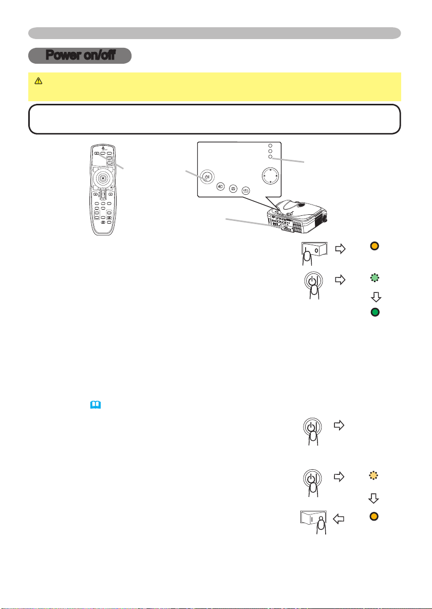
Turning on the power
POWER
Make sure that the power cord is firmly and correctly
1.
connected to the projector and outlet.
Remove the lens cap, and set the power switch to the
2.
ON position.
The power indicator will light to solid orange. Then wait
several seconds because buttons may not function for
these several seconds.
Press the STANDBY/ON button on the projector or remote control.
3.
The projector lamp will light up and the POWER indicator will begin blinking
green. When the power is completely on, the indicator will stop blinking light
green.
To display the picture, select an input signal according to the section "Selecting an
input signal"
(17)
.
Turning off the power
Press the STANDBY/ON button on the projector or
1.
remote control.
The message "Power off?" will appear on the screen for
approximately 5 seconds.
Press the STANDBY/ON button on the projector or
2.
remote control again while the message is visible.
The projector lamp will go off, and the POWER indicator
will begin blinking orange.
Then the POWER indicator will stop blinking and light to
solid orange when the lamp cooling is complete.
3.
Make sure that the power indicator lights to solid orange, set the power switch
to the OFF position. The POWER indicator will go off. Attach the lens cap.
POWER
(Solid orange)
POWER
(Blinking green)
POWER
(Solid green)
Power off?
POWER
(Blinking orange)
POWER
(Solid orange)
Page 29
Operating
STANDBY/ON
VIDEO
UP
DOWN
BLANK
ASPECT
PUSH
LASER
INDICATOR
LASER
RGB
ENTER
ON
OFF
ESC
POSITION
MAGNIFY
MUTE
KEYSTONE
FREEZE
ONE TOUCH
AUTO
PA
GE
MENU
RESET
VOLUME
STANDBY/ON
VIDEO
UP
DOWN
BLANK
ASPECT
PUSH
LASER
INDICATOR
LASER
RGB
ENTER
ON
OFF
ESC
POSITION
MAGNIFY
MUTE
KEYSTONE
FREEZE
ONE TOUCH
AUTO
PA
GE
MENU
RESET
VOLUME
STANDBY/ON
VIDEO
UP
LASER
INDICATOR
RGB
STANDBY/ON
VIDEO
UP
LASER
INDICATOR
RGB
INPU
T
KEYSTO NE
RESE
T
MENU
POWER
TEMP
LAMP
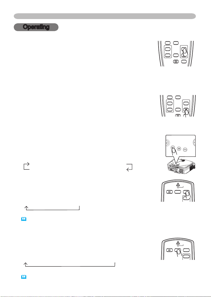
Adjusting the volume
Press the VOLUME button on the remote control.
1.
A dialog will appear on the screen to aid you in adjusting
the volume.
Use the cursor buttons ▲/▼ to adjust the volume.
2.
To close the dialog and complete the operation, press the VOLUME button
again. Even if you don’t do anything, the dialog will automatically disappear
after a few seconds.
Temporarily muting the sound
Press the MUTE button on the remote control.
1.
A dialog will appear on the screen indicating that you have
muted the sound.
To restore the sound, press the MUTE or VOLUME button.
Even if you don’t do anything, the dialog will automatically disappear after a few
seconds.
Selecting an input signal
Press the INPUT button on the projector.
1.
Each time you press the button, the projector switches its input
port as below.
RGB IN1 RGB IN2 DVI-D
VIDEO S-VIDEO COMPONENT VIDEO
Press the RGB button on the remote control to select an
1.
input port for RGB signal.
Each time you press the button, the projector switches its
RGB input port as below.
RGB IN1 RGB IN2 DVI-D
● When the TURN ON is selected to the item AUTO SEARCH of OPTION menu
(38)
, the projector checks the current selected port at first. If no input is
detected at the port, projector will check other ports in above order.
Operating
Press the VIDEO button on the remote control to select an
1.
input for video signal.
Each time you press the button, the projector switches its
video input port as below.
COMPONENT VIDEO
● When the TURN ON is selected to the item AUTO SEARCH of OPTION menu
(38)
, the projector checks the current selected video port at first. If no input is
detected at the port, projector will begin to check other ports in above order.
S-VIDEO VIDEO
17
Page 30
18
Operating
STANDBY/ON
VIDEO
UP
DOWN
BLANK
ASPECT
LASER
INDICATOR
LASER
RGB
PA
GE
STANDBY/ON
VIDEO
UP
DOWN
BLANK
ASPECT
PUSH
LASER
INDICATOR
LASER
RGB
ENTER
ON
OFF
ESC
POSITION
MAGNIFY
MUTE
KEYSTONE
FREEZE
ONE TOUCH
AUTO
PA
GE
MENU
RESET
VOLUME
Adjusting screen with ONE-TOUCH
Press the ONE TOUCH button on the remote control. This
1.
activates the following functions at one time.
Signal search: Projector will cycle through its input ports in
order to find any input signal. The search is started from the
current port. Then when an input is found, the projector will
stop searching and display the image. If no signal is found, the projector will
return to the state selected before the operation.
RGB IN1 RGB IN2 DVI-D
Auto adjust: Projector automatically adjusts the picture position and size in
RGB mode, and automatically selects the signal mode in VIDEO input
Automatic keystone distortion correction: Projector automatically corrects
vertical keystone distortion due to the (forward/backward) setup angle by itself.
This is only performed if ONE TOUCH of the OPTION menu is set to TURN ON
(38)
.
COMPONENT VIDEO
S-VIDEO VIDEO
(29)
.
Selecting an aspect ratio
Press the ASPECT button on the remote control.
1.
Each time you press the button, the projector switches the mode for aspect
ratio in turn.
At a RGB/DVI signal
NORMAL
4:3 16:9
At a video signal/no signal
4:3 16:9 SMALL
● The NORMAL mode keeps the original aspect ratio of the signal.
● At a HDTV signal of 1125i (1080i) or 750p (720p) of COMPONENT VIDEO
input, only 16:9 mode can be selected.
● Performing the automatic adjustment initializes the aspect ratio setting.
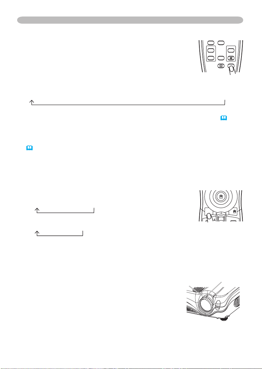
Adjusting the zoom and focus
Use the zoom knob to adjust the screen size.
1.
Use the focus ring to focus the picture.
2.
Focus ring
Zoom knob
Page 31
Operating
STANDBY/ON
VIDEO
UP
DOWN
BLANK
ASPECT
PUSH
LASER
INDICATOR
LASER
RGB
ENTER
ON
ESC
POSITION
MAGNIFY
AUTO
PA
GE
MENU
RESET
VOLUME
STANDBY/ON
VIDEO
UP
DOWN
BLANK
ASPECT
PUSH
LASER
INDICATOR
LASER
RGB
ENTER
ESC
POSITION
MAGNIFY
AUTO
PA
GE
MENU
RESET
VOLUME
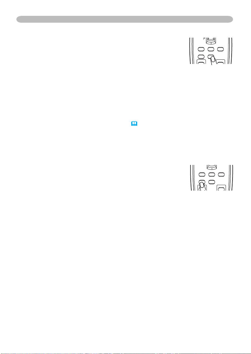
Using the automatic adjustment feature
Press the AUTO button on the remote control.
1.
At a RGB signal
The vertical position, the horizontal position, the clock
phase and horizontal size will be automatically adjusted.
Make sure that the application window is set to its maximum size prior to
attempting to use this feature. A dark picture may still be incorrectly adjusted.
Use a bright picture when adjusting.
At a video signal
The video format best suited for the respective input signal will be selected
automatically.
This function is available only when the AUTO mode is selected to the item
(32)
VIDEO FORMAT of the INPUT menu
. For a component video signal,
the signal type is identified automatically independently of this function.
● The automatic adjustment operation requires approximately 10 seconds. Also
please note that it may not function correctly with some input.
Adjusting the position
Press the POSITION button on the remote control.
1.
The “POSITION” indication will appear on the screen.
Use the cursor buttons ▲/▼/◄/► to adjust the picture
2.
position.
When you want to reset the operation, press the RESET button on the remote
control during the operation.
To complete this operation, press the POSITION button again. Even if you don’t
do anything, the dialog will automatically disappear after a few seconds.
● When this function is performed at a video signal, a certain extra such as a line
may appear outside a picture.
● This function does not work when DVI-D input port is selected.
19
Page 32
20
STANDBY/ON
VIDEO
UP
DOWN
BLANK
ASPECT
PUSH
LASER
INDICATOR
LASER
RGB
ENTER
ON
ESC
POSITION
MAGNIFY
MUTE
FREEZE
AUTO
PA
GE
MENU
RESET
VOLUME
Operating
STANDBY/ON
VIDEO
UP
DOWN
BLANK
ASPECT
PUSH
LASER
INDICATOR
LASER
RGB
ENTER
ON
OFF
ESC
POSITION
MAGNIFY
MUTE
KEYSTONE
FREEZE
ONE TOUCH
AUTO
PA
GE
MENU
RESET
VOLUME
INPU
T
KEYSTO NE
RESE
T
MENU
POWER
TEMP
LAMP
+0 +0
KEYSTONE
KEYSTONE
AUTO EXECUTE
MANUAL
+0
+0
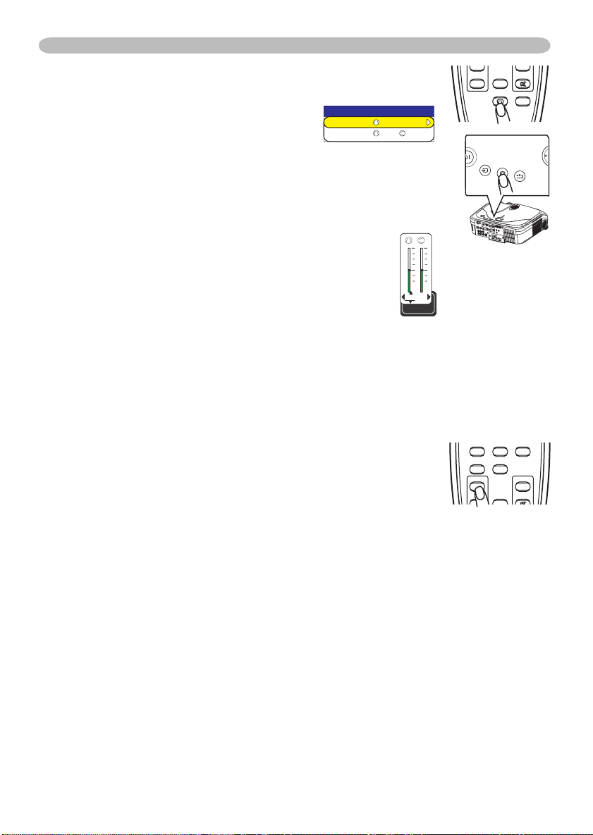
Correcting the keystone distortions
Press the KEYSTONE button on the projector or the
1.
remote control. A dialog will appear on
the screen to aid you in correcting the
distortion.
Use the cursor buttons ▲/▼ to select AUTO or MANUAL
2.
operation, and press the button ► to perform the following.
1) AUTO executes automatic vertical keystone correction.
This does not support horizontal keystone correction.
2) MANUAL displays a dialog for horizontal and
vertical keystone correction.
Select each of them with the button ►, and use the
buttons ▲/▼ for adjustment.
To close the dialog and complete this operation, press
the KEYSTONE button again. Even if you don’t do
anything, the dialog will automatically disappear after
a few seconds.
● This function may not be work well with some input.
● The adjustable range for correcting will vary among inputs.
Using the magnify feature
Press the ON button of MAGNIFY on the remote control.
1.
The “MAGNIFY” indication will appear on the screen
(although the indication will disappear in several seconds
with no operation), and the projector will enter the MAGNIFY
mode.
Use the cursor buttons ▲/▼ to adjust the zoom level.
2.
To move the zoom area, press the POSITION button in the MAGNIFY mode,
then use the cursor buttons ▲/▼/◄/► to move the area. And to finalize the
zoom area, press the POSITION button again.
To exit the MAGNIFY mode and restore the screen to normal, press the OFF
button of MAGNIFY on the remote control.
● The projector automatically exits the MAGNIFY mode when the input signal
changes, or when an operation of changing the display condition (automatic
adjustment, etc.) is executed.
● Although in the MAGNIFY mode, the keystone distortion condition may vary, it
will be restored when the projector exit the MAGNIFY mode.
Page 33
STANDBY/ON
VIDEO
UP
DOWN
BLANK
ASPECT
PUSH
LASER
INDICATOR
LASER
RGB
ENTER
ON
OFF
ESC
POSITION
MAGNIFY
MUTE
KEYSTONE
FREEZE
ONE TOUCH
AUTO
PA
GE
MENU
RESET
VOLUME
STANDBY/ON
VIDEO
UP
DOWN
BLANK
LASER
INDICATOR
LASER
RGB
PA
GE
Operating
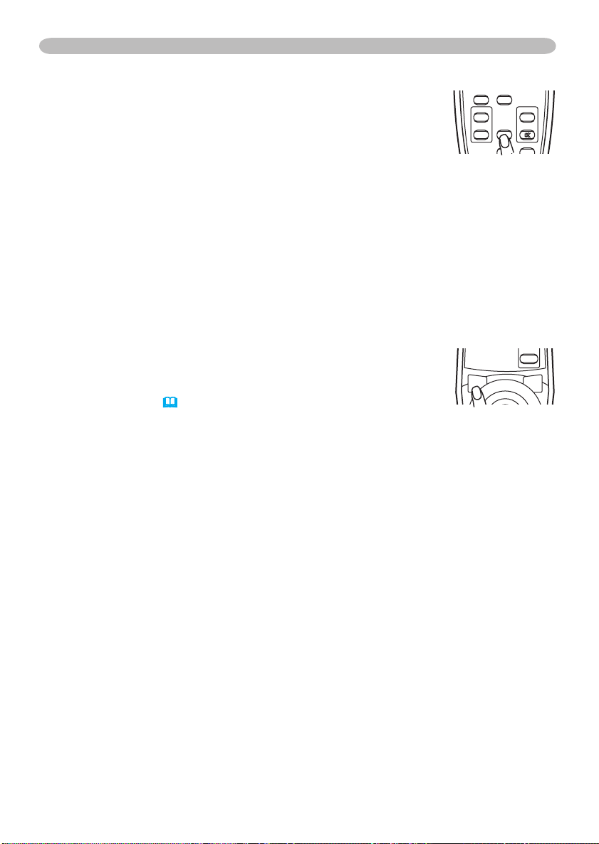
Freezing the screen
Press the FREEZE button on the remote control.
1.
The “FREEZE” indication will appear on the screen, and
the projector will enter the FREEZE mode.
To exit the FREEZE mode and restore the screen to normal,
press the FREEZE button again.
● The projector automatically exits the FREEZE mode when the input signal
changes, or when one of the projector’s buttons or the remote control buttons
of STANDBY/ON, ONE TOUCH, RGB, VIDEO, BLANK, AUTO,ASPECT,
VOLUME, MUTE, KEYSTONE, POSITION and MENU is pressed.
● If the projector continues projecting a still image for long time, the LCD panel
might possibly be printed. Do not leave the projector in FREEZE mode for too
long.
Temporarily blanking the screen
Press the BLANK button on the remote control.
1.
The blank screen will be displayed instead of the screen
of input signal. Please refer to the item BLANK of section
SCREEN menu
To remove the blank screen and return to the input signal screen, press the
BLANK button again.
● The projector automatically returns to the input signal screen when the input
signal changes, or when one of the projector’s buttons or the remote control
buttons except the disk pad including the center button for the left click or the
right mouse button is pressed.
(35).
21
Page 34
22
Operating
Operating the computer screen
CAUTION ►Mistaken use of the mouse/keyboard control could damage
your equipment.
• While using this function, please connect only with a computer.
• Before connecting, read the manuals of the computer you will connect.
NOTE • It may not be possible to control notebook PC, and other computers with
built-in pointing device (e.g. track ball), using this remote control. In this case, before
connecting go into BIOS (system setup) and select external mouse, and disable the
pointing device. In addition, the mouse may not function if the computer does not have
the needed utility program. See your computer’s hardware manual for details.
• The USB control can be used with Windows 95 OSR 2.1 or higher. It may not be
possible to use the remote control, depending on the computer’s configurations and
mouse drivers.
• The USB control can be used only for the functions listed below. You cannot do things
like press two buttons at once (for instance, pressing two buttons at the same time to
move the mouse pointer diagonally).
• This function is not available while the lamp is warming up (the POWER indicator
flashes green), and while adjusting the volume and display, correcting for trapezoidal
distortion, zooming in on the screen, using the BLANK function, or displaying the menu
screen.
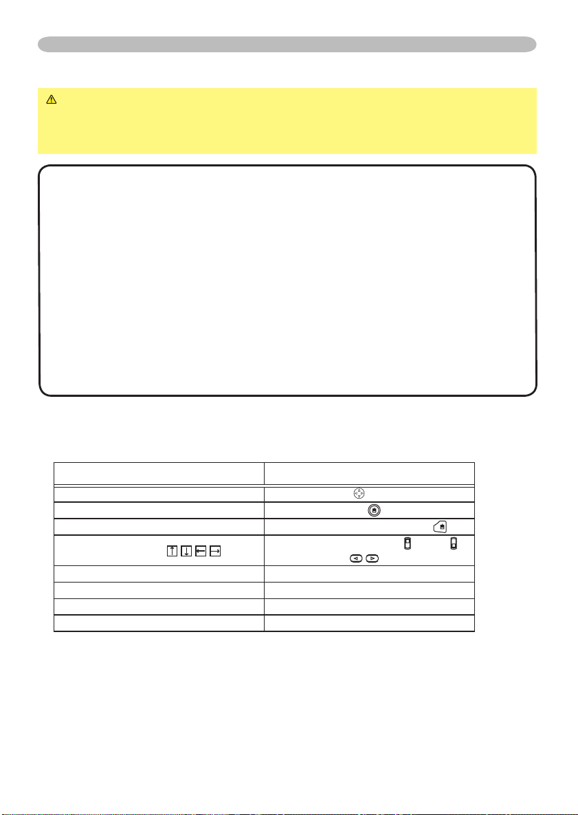
USB mouse and keyboard control
Connect the projector’s USB port to the computer via the mouse cable.
1.
Available function Remote control operation
Move pointer Move using on the disk pad
Left click with mouse Press the center of the disk pad
Right click with mouse Press right mouse button
keys
Press keyboard’s
Press keyboard’s ENTER key Press ENTER button
Press keyboard’s PAGE UP key Press PAGE UP button
Press keyboard’s PAGE DOWN key Press PAGE DOWN button
Press keyboard’s ESC key
Flip the lever switch up /down ,
press buttons
Press ESC button
Page 35
Operating
STANDBY/ON
VIDEO
UP
DOWN
BLANK
ASPECT
PUSH
LASER
INDICATOR
LASER
RGB
ENTER
ON
OFF
ESC
POSITION
MAGNIFY
MUTE
KEYSTONE
FREEZE
ONE TOUCH
AUTO
PA
GE
MENU
RESET
VOLUME
STANDB Y/ON
INPU
T
KEYST ONE
RESE
T
MENU
POWER
TEMP
LAMP
STANDBY/ON
VIDEO
UP
DOWN
BLANK
ASPECT
PUSH
LASER
INDICATOR
LASER
RGB
ENTER
ESC
POSITION
MAGNIFY
AUTO
PA
GE
MENU
RESET
VOLUME
EASY MENU
CONTRAST
ASPECT 4:3
BRIGHT
MODE NORMAL
COLOR
+0
+0
+0
TINT
+0
SHARPNESS
+3
WHISPER NORMAL
RESET
FILTER TIME 0
LANGUAGE ENGLISH
Go To Advance Menu...
MIRROR NORMAL
MENU [RGB]
IMAGE
SETUP
PICTURE
INPUT
OPTION
NETWORK
SCREEN
SHARPNESS +0
BRIGHT +0
CONTRAST +0
COLOR +0
TINT +0
COLOR TEMP 6500K
GAMMA DEFAULT 1
MY MEMORY SAVE 1
:SELECT
VIDEO Qlty.
EASY MENU
Multifunctional settings
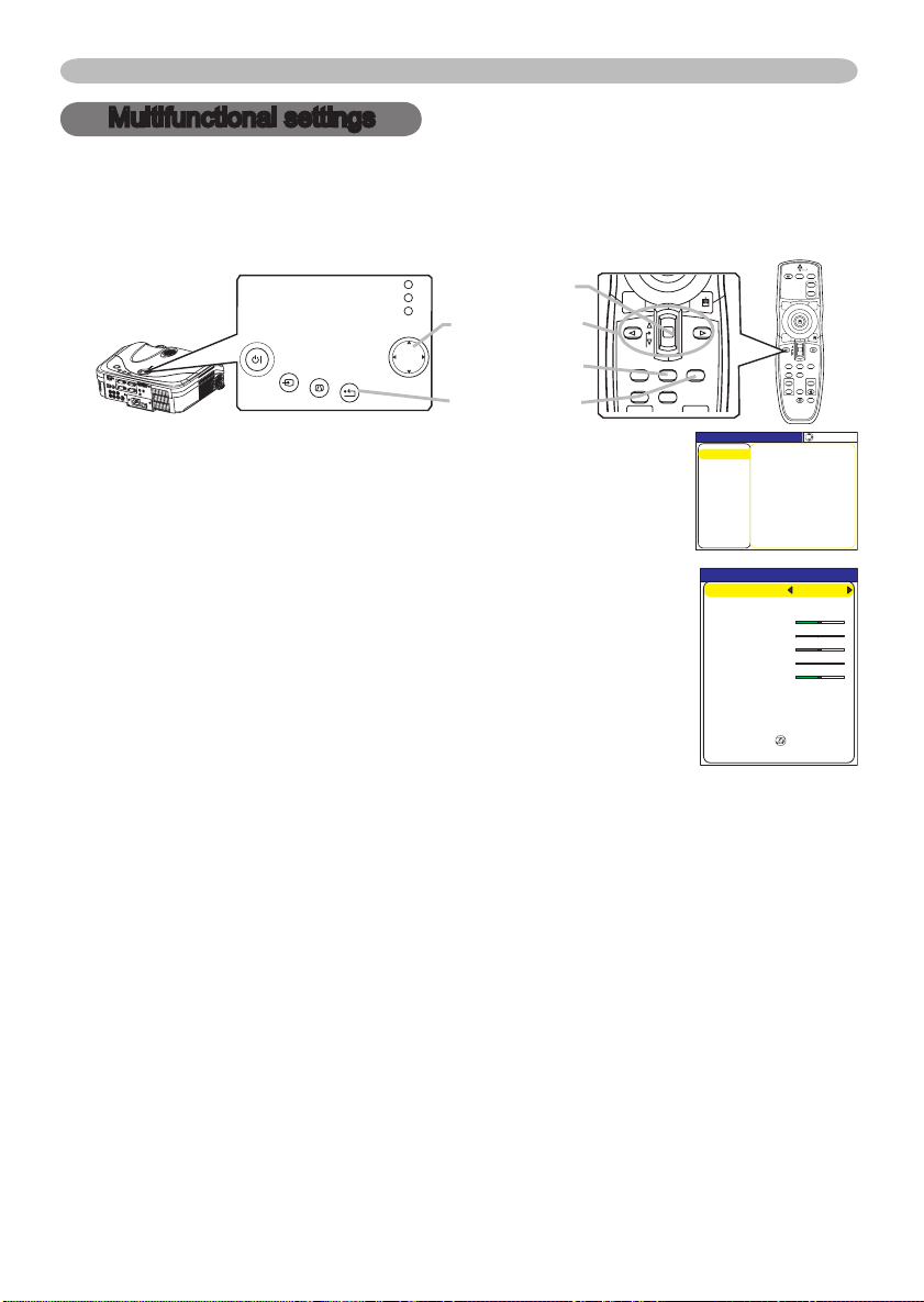
Using the menu function
This projector has the following menus: PICTURE, IMAGE, VIDEO Qlty., INPUT, SETUP,
SCREEN, OPTION, NETWORK and EASY MENU. Each of these menus is operated using
the same methods. The basic operations of these menus are as follows.
ENTER button
Cursor buttons
MENU button
RESET button
Press the MENU button on the remote control or one of
1.
the cursor buttons on the projector.
The advanced MENU or EASY MENU will appear.
At the EASY MENU
If you want to change it to the advanced MENU, select the
2.
"Go to Advanced Menu".
Use the cursor buttons ▲/▼ to select an item to operate.
3.
Use the cursor buttons◄/► to operate the item.
4.
At the advanced MENU
Use the cursor buttons ▲/▼ to select a menu.
2.
If you want to change it to the EASY MENU, select the
EASY MENU.
Then press the cursor button ► on the projector or remote
control, or the ENTER button on the remote control to progress. The display of
the selected menu will be active.
Use the cursor buttons ▲/▼ to select an item to operate.
3.
Then press the cursor button ► on the projector or remote control, or the ENTER button
on the remote control to progress. The operation menu of the selected item will appear.
Use the cursor buttons▲/▼ to operate the item.
4.
● When you want to reset the operation, press the RESET button on the remote
control during the operation. Note that items whose functions are performed
simultaneously with operation (ex. LANGUAGE, H PHASE etc.) aren't reset.
●
At the advanced menu, when you want to return to the previous display, press the cursor
button ◄ on the projector or remote control, or the ESC button on the remote control.
5.
● Some functions cannot be performed when a certain input port is selected, or
Press the MENU button on the remote control again to close the menu
and complete this operation. Even if you don't do anything, the dialog will
automatically disappear after about 10 seconds.
when a certain input signal is displayed.
23
Page 36
24
Multifunctional settings
EASY MENU
CONTRAST
ASPECT 4:3
BRIGHT
MODE NORMAL
COLOR
+0
+0
+0
TINT
+0
SHARPNESS
+3
WHISPER NORMAL
RESET
FILTER TIME 0
LANGUAGE ENGLISH
Go To Advance Menu...
MIRROR NORMAL
EASY Menu
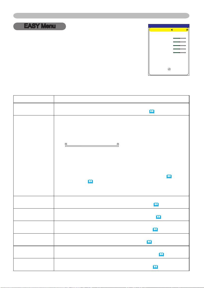
With the EASY MENU, items shown in the table below can
be performed.
Select an item using the cursor buttons ▲/▼ on the
projector or remote control. Then perform it referring to the
following table.
Item Description
ASPECT
MODE
BRIGHT
CONTRAST
COLOR
TINT
SHRPNESS
WHISPER
Using the buttons ◄/► switches the mode for aspect ratio.
See the item ASPECT of section IMAGE menu
Using the buttons ◄/► switches the mode of picture type. The
modes of picture type are combinations of a mode of GAMMA and
a mode of COLOR TEMP
. Choose a suitable mode according to the
projected source.
NORMAL
CINEMA
DYNAMIC
NORMAL: (COLOR TEMP = MIDDLE) + (GAMMA = #1 DEFAULT)
CINEMA: (COLOR TEMP = LOW) + (GAMMA = #2 DEFAULT)
DYNAMIC: (COLOR TEMP = HIGH) + (GAMMA = #3 DEFAULT)
• When the combination of GAMMA and COLOR TEMP differs
from pre-assigned modes above, the display on the menu for the
MODE is “CUSTOM”. Please refer to the items GAMMA
COLOR TEMP
(27) of PICTURE menu.
• When this function is performed, a certain extra such as a line
may appear.
Using the buttons ◄/► adjusts the brightness.
See the item BRIGHT of section PICTURE menu (26).
Using the buttons ◄/► adjusts the contrast.
See the item CONTRAST of section PICTURE menu (26).
Using the buttons ◄/► adjusts the strength of whole color.
See the item COLOR of section PICTURE menu (27).
Using the buttons ◄/► adjusts the tint.
See the item TINT of section PICTURE menu (27).
Using the buttons ◄/► adjusts the sharpness.
See the item SHARPNESS of section PICTURE menu (27).
Using the buttons ◄/► turns off/on the whisper mode.
See the item WHISPER of section SETUP menu (34).
(29).
(26) and
Page 37
EASY Menu (continued)
Item Description
MIRROR
RESET
FILTER TIME
LANGUAGE
Go To
Advanced Menu
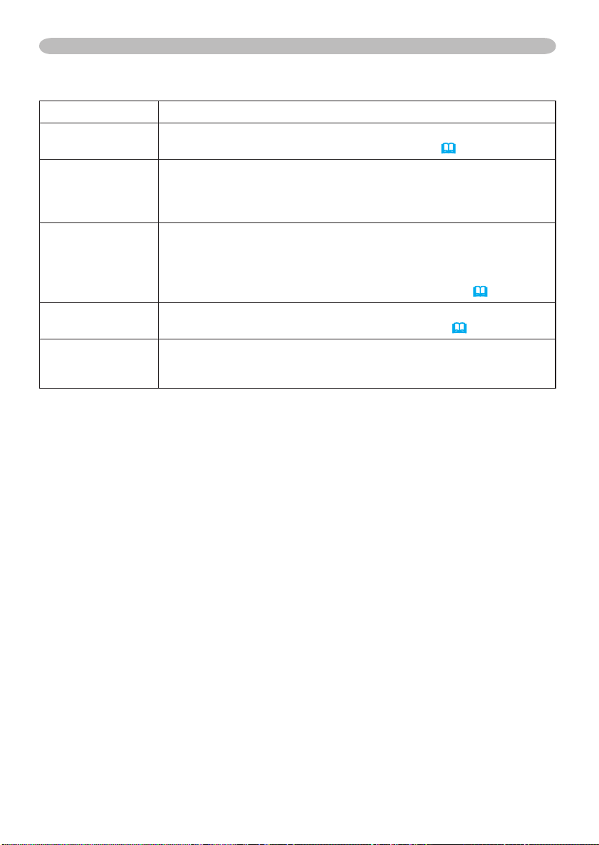
Using the buttons ◄/► switches the mode for mirror status.
See the item MIRROR of section SETUP menu (34).
Performing this item resets all of the items of EASY MENU except
FILTER TIME and LANGUAGE.
A dialog is displayed to make sure. Selecting RESET using the
button ▲ performs reset.
Performing this item resets the filter timer which counts use time of
air filter.
A dialog is displayed to make sure. Selecting RESET using the
button ▲ performs reset.
See the item FILTER TIME of section OPTION menu (39).
Select the LANGUAGE to toggle the menu language. Refer to
description of LANGUAGE in the SCREEN menu (35).
Select the “Go To Advanced Menu” to use the
IMAGE, VIDEO Qlty., INPUT, SETUP, SCREEN, OPTION or
NETWORK.
Multifunctional settings
menu of PICTURE,
25
Page 38
26
Multifunctional settings
1
+0
2
+0
3
+0
4
+0
5
+0
6
+0
7
+0
8
+0
GAMMA [CUSTOM 1
]
ENTER :
MENU [RGB]
IMAGE
SETUP
PICTURE
INPUT
OPTION
NETWORK
SCREEN
SHARPNESS +0
BRIGHT +0
CONTRAST +0
COLOR +0
TINT +0
COLOR TEMP 6500K
GAMMA DEFAULT 1
MY MEMORY SAVE 1
:SELECT
VIDEO Qlty.
EASY MENU
PICTURE Menu
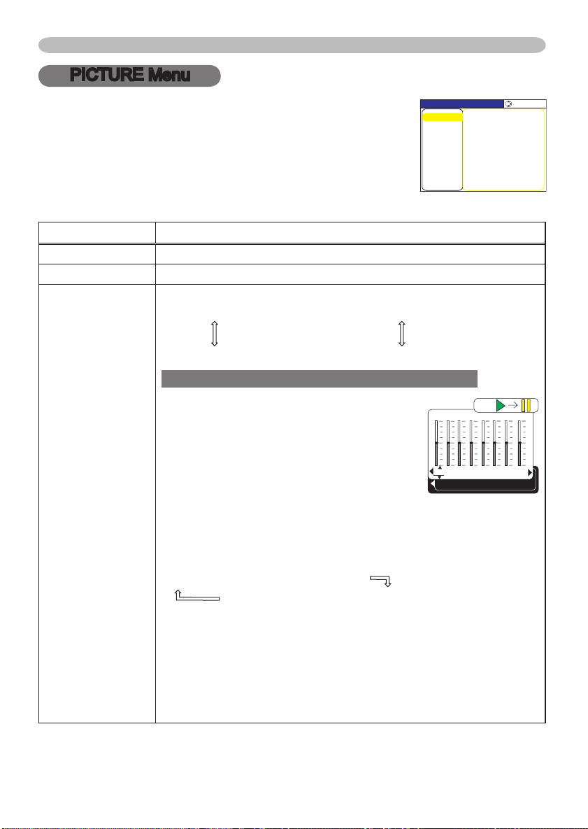
With the PICTURE menu, items shown in the table below
can be performed.
Select an item using the cursor buttons ▲/▼ on the
projector or remote control, and press the cursor button ►
on the projector or remote control, or the ENTER button on
the remote control to progress. Then perform it referring to
the following table.
Item Description
BRIGHT Using the buttons ▲/▼ adjusts the brightness. : Light Dark
CONTRAST Using the buttons ▲/▼ adjusts the contrast. : Strong
Using the buttons ▲/▼ switches the GAMMA mode.
#1 DEFAULT
#1 CUSTOM #2 DEFAULT
Weak
GAMMA
#3 CUSTOM
#3 DEFAULT #2 CUSTOM
To adjust #1 CUSTOM, #2 CUSTOM or #3 CUSTOM
Selecting a mode of CUSTOM and then
pressing the button ► or the ENTER button
displays a dialog to aid you in adjusting the
mode.
This function is useful when you want to
change the brightness of particular tones.
Choose an item using the buttons ◄/►, and
adjust the level using the buttons ▲/▼.
You can display a test pattern for checking the effect of your
adjustment by pressing the ENTER button.
Each time you press the ENTER button, the pattern changes as
below.
No pattern Gray scale of 9 steps
Ramp Gray scale of 15 steps
Eight of equalizing bars corresponds to eight of tone level of test
pattern except the darkest in the left end. If you want to adjust
the 2nd tone from left end on the test pattern, use the equalizing
adjustment bar “1”. The darkest tone at the left end of the test
pattern cannot be controlled with any of equalizing adjustment bar.
• When this function is performed, a certain extra such as a line
may appear.
Page 39
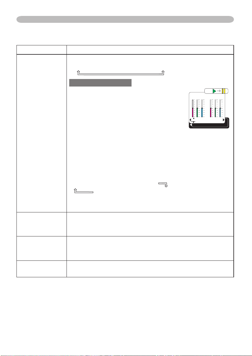
PICTURE Menu (continued)
R
+0
G
+0
B
+0
COLOR TEMP
ENTER :
OFFSET
R
+0
G
+0
B
+0
GAIN
Item Description
Using the buttons ▲/▼ switches the mode of color temperature.
HIGH MIDDLE LOW
To adjust CUSTOM
Selecting the CUSTOM and then pressing the
button ► or the ENTER button displays a dialog
to aid you in adjusting the OFFSET and/or GAIN
of CUSTOM mode.
OFFSET adjustments change the color intensity
on the whole tones of the test pattern.
COLOR TEMP
COLOR
TINT
SHARPNESS
GAIN adjustments mainly affect color intensity
on the brighter tones of the test pattern.
Choose an item using the buttons ◄/►, and adjust the level using
the buttons ▲/▼.
You can display a test pattern for checking the effect of your
adjustment by pressing the ENTER button.
Each time you press the ENTER button, the pattern changes as
below.
No pattern Gray scale of 9 steps
Ramp Gray scale of 15 steps
• When this function is performed, a certain extra such as a line
may appear.
Using the buttons ▲/▼ adjusts the strength of whole color.
Strong
• This item can be selected only at a video signal.
Using the buttons ▲/▼ adjusts the tint.
Green Red
• This item can be selected only at a video signal.
Using the buttons ▲/▼ adjusts the sharpness.
Strong
Weak
Weak
CUSTOM
Multifunctional settings
27
Page 40
28
Multifunctional settings
PICTURE Menu (continued)
Item Description
Selecting a mode of MY MEMORY using the buttons ▲/▼ and then
pressing the button ► or the ENTER button performs each function.
LOAD1 LOAD2 LOAD3 LOAD4
MY MEMORY
SAVE4
This projector has 4 numbered memories for adjustment data.
Performing the LOAD1, LOAD2, LOAD3 or LOAD4 loads the data
on the memory whose number corresponds with the command’s
number, and adjusts the picture automatically depending on the data.
Performing the SAVE1, SAVE2, SAVE3 or SAVE4 puts the current
adjustment data on the memory whose number corresponds with
the command’s number.
• Current adjustment data of the items in the PICTURE menu is
stored.
• Although adjustment data under the CUSTOM in the items of
GAMMA and COLOR TEMP is not
CUSTOM is selected
SAVE3 SAVE2 SAVE1
stored, it is memorized that the
.
Page 41
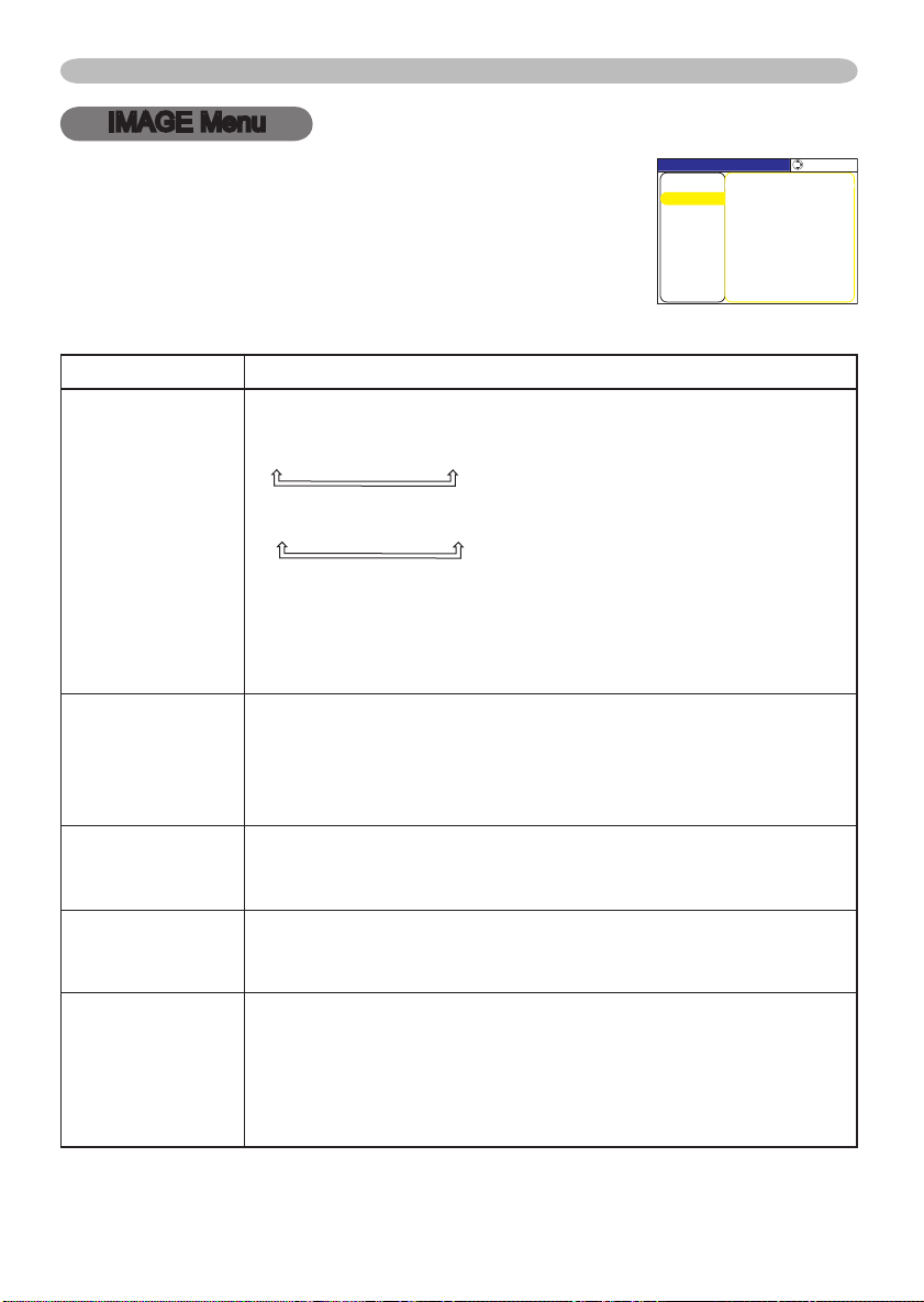
IMAGE Menu
MENU [RGB]
IMAGE
PICTURE
:SELECT
AUTO ADJUST EXECUTE
ASPECT 4:3
OVER SCAN 95
H PHASE 16
H SIZE 1344
H POSITION 142
V POSITION 25
SETUP
INPUT
OPTION
EASY MENU
SCREEN
VIDEO Qlty.
NETWORK
With the IMAGE menu, items shown in the table below can
be performed.
Select an item using the cursor buttons ▲/▼ on the
projector or remote control, and press the cursor button ►
on the projector or remote control, or the ENTER button on
the remote control to progress. Then perform it referring to
the following table.
Item Description
Using the buttons ▲/▼ switches the mode for aspect ratio.
At a RGB/DVI signal
4:3 16:9 NORMAL
At a video signal / no signal
4:3 16:9 SMALL
• The NORMAL mode keeps the original aspect ratio of the signal.
• At a HDTV signal of 1125i (1080i) or 750p (720p) of COMPONENT
VIDEO input, this item can't be selected.
• Performing the automatic adjustment initializes the aspect ratio
setting.
Using the buttons ▲/▼ adjusts the over-scan ratio.
Large (It reduces picture)
• This item can be selected only at a video signal.
• When this adjustment is too large, certain degradation may appear
at the frame area of the picture. In such a case, please adjust small.
Using the buttons ▲/▼ adjusts the vertical position.
Up Down
This itemis not selected when DVI-D input port is selected.
Using the buttons ▲/▼ adjusts the horizontal position.
Left Right
This itemis not selected when DVI-D input port is selected.
Using the buttons ▲/▼ adjusts the horizontal phase to eliminate
flicker.
Right Left
• This item can be selected only at a RGB signal or a component
video signal. Note that this does not work with the input signal of
525i(480i)/625i(576i) from the component video port.
ASPECT
OVER SCAN
V POSITION
H POSITION
H PHASE
Multifunctional settings
Small (It magnifies picture)
29
Page 42

30
Multifunctional settings
IMAGE Menu (continued)
Item Description
Using the buttons ▲/▼ adjusts the horizontal size.
Large Small
H SIZE
AUTO ADJUST
EXECUTE
• This item can be selected only at a RGB signal (except DVI-D).
• When this adjustment is excessive, the picture may not be
displayed correctly. In such a case, please reset the adjustment
pressing the RESET button on the remote control during this
operation.
Selecting this item performs the automatic adjustment feature.
At a RGB signal
The vertical position, the horizontal position, the clock phase and
horizontal size will be automatically adjusted.
Make sure that the application window is set to its maximum size
prior to attempting to use this feature. A dark picture may still be
incorrectly adjusted. Use a bright picture when adjusting.
At a video signal
The video format best suited for the respective input signal will be
selected automatically.
This function is available only when the AUTO mode is selected to
the item VIDEO FORMAT of INPUT menu. For a component video
signal, the signal type is identified automatically independently of
this function.
• The automatic adjustment operation requires approximately 10
seconds. Also please note that it may not function correctly with
some input.
Page 43
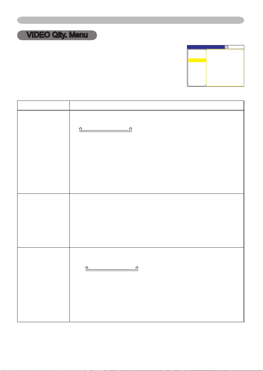
Multifunctional settings
MENU [RGB]
IMAGE
PICTURE
:SELECT
SETUP
INPUT
OPTION
EASY MENU
SCREEN
VIDEO Qlty.
NETWORK
PROGRESSIVE TURN OFF
3D‑YCS TURN OFF
VIDEO NR LOW
VIDEO Qlty. Menu
With the VIDEO Qlty. menu, items shown in the table below
can be performed.
Select an item using the cursor buttons ▲/▼ on the
projector or remote control, and press the cursor button ►
on the projector or remote control, or the ENTER button on
the remote control to progress. Then perform it referring to
the following table.
Item Description
Using the buttons ▲/▼ switches the progressive mode.
TV FILM TURN OFF
• This function performs only at an interlaced signal of a VIDEO
input, a S-VIDEO input or a COMPONENT VIDEO input of 525i
PROGRESSIVE
3D-YCS
VIDEO NR
(480i) or 625i (576i) signal.
• When the TV or FILM is selected, the screen image will be crisper.
The FILM mode is adaptable to the 2-3 Pull-Down system to the
conversion. But these may cause a certain defect (for example,
jagged line) of the picture at a quick moving object. In such a case,
please select the TURN OFF, even though the screen image may
lose the crisp.
Using the buttons ▲/▼ switches the 3D-YCS mode.
STILL IMAGE
NORMAL
TURN OFF
• This function performs only at a VIDEO input of NTSC 3.58.
• NORMAL is the mode for images with a lot of motions like movies,
and STILL IMAGE is the mode for images with few motions or
completely still ones like slides.
• When this function performs, the VIDEO NR function is ineffective.
Using the buttons ▲/▼ switches the noise reduction mode.
HIGH MIDDLE LOW
• This function performs only at a VIDEO input or a S-VIDEO input.
At a VIDEO input of NTSC 3.58, this function performs only when
the TURN OFF is selected under the 3D-YCS.
• When the HIGH, the MIDDLE or the LOW is selected, the noise
on screen is reduced according to each mode.
• When this function is excessive, it may cause a certain
degradation of the picture.
31
Page 44
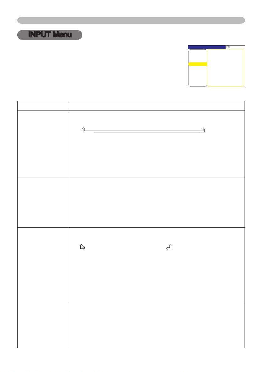
32
Multifunctional settings
MENU [RGB]
IMAGE
SETUP
PICTURE
INPUT
OPTION
EASY MENU
SCREEN
:SELECT
VIDEO FORMAT AUTO
COLOR SPACE AUTO
INFORMATION
COMPONENT COMPONENT
DVI DVD
VIDEO Qlty.
NETWORK
INPUT Menu
With the INPUT menu, items shown in the table below can
be performed.
Select an item using the cursor buttons ▲/▼ on the
projector or remote control, and press the cursor button ►
on the projector or remote control, or the ENTER button on
the remote control to progress. Then perform it referring to
the following table.
Item Description
Using the buttons ▲/▼ switches the mode for color space.
AUTO RGB SMPTE240 REC709 REC601
• This item can be selected only at a RGB signal or a component
video signal (except signals of 525i(480i)/625i(576i) from the
component video port).
• The AUTO mode automatically selects the optimum mode.
• The AUTO operation may not work well at some signals. In such a
case, it might be good to select the SMPTE240 or the REC709.
Using the buttons ▲/▼ switches the function of COMPONENT
VIDEO port.
COMPONENT
SCART RGB
When the SCART RGB is selected, the COMPONENT VIDEO port
function as a port for a SCART RGB signal input. A SCART adapter
and SCART cable realize a SCART RGB input to the projector. For
details, ask your dealer.
Using the buttons ▲/▼ switches the mode for video format.
AUTO
NTSC
PAL
N-PAL M-PAL NTSC4.43
• This item performs only at a video signal from the VIDEO port or
the S-VIDEO port. For a component video signal, the signal type is
identified automatically independently of this function.
• The AUTO mode automatically selects the optimum mode.
• The AUTO operation may not work well at some signals. If the
picture becomes unstable (ex. an irregular picture, a color lack),
please select the mode depending on the input signal.
Select a signal source of the DVI-D port using the ▲/▼ buttons.
COMPUTER DVD
• If unsuitable setting is chosen, brightest or darkest tones may not
be displayed correctly.
• When you watch the DVD, always choose the “DVD” in spite of
the signal source, the computer or the DVD player.
COLOR SPACE
COMPONENT
VIDEO FORMAT
DVI
SECAM
Page 45
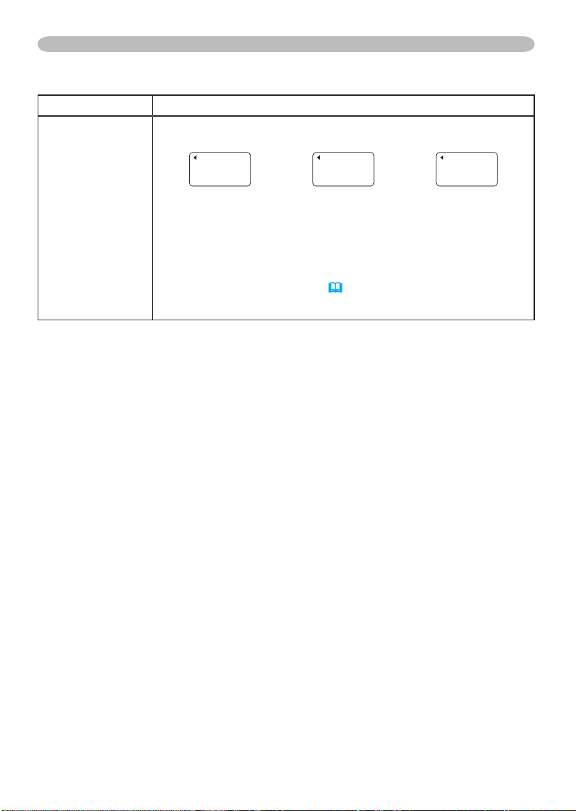
INPUT Menu (continued)
INPUT-INFORMATION
RGB
1024x768 @60.0
FRAME LOCK
INPUT-INFORMATION
S-VIDEO
SECAM
AUTO
INPUT-INFORMATION
COMPONENT
576i @50
SCART RGB
Item Description
Selecting this item displays a dialog titled “INPUT INFORMATION”.
It shows the information about the current input.
• The “FRAME LOCK” message on the dialog means the frame lock
INFORMATION
function is working. This function automatically works when a RGB
signal with vertical frequency of 50 to 60 Hz is input, and it displays
a moving picture more smoothly.
• The “SCART RGB” message means the COMPONENT VIDEO
port is working as a SCART RGB input port. Please refer to the item
COMPONENT in this section.
• This item can't be selected at no signal and sync out.
(32)
Multifunctional settings
33
Page 46
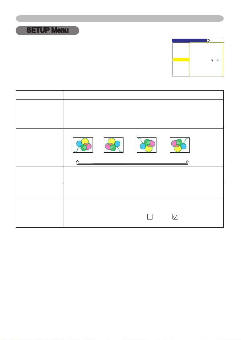
34
Multifunctional settings
MENU [RGB]
IMAGE
SETUP
PICTURE
INPUT
OPTION
EASY MENU
SCREEN
:SELECT
WHISPER NORMAL
MIRROR NORMAL
STEREO MONO
VOLUME 16
IR REMOTE 1: 2:
VIDEO Qlty.
NETWORK
SETUP Menu
With the SETUP menu, items shown in the table below can
be performed.
Select an item using the cursor buttons ▲/▼ on the
projector or remote control, and press the cursor button ►
on the projector or remote control, or the ENTER button on
the remote control to progress. Then perform it referring to
the following table.
Item Description
Using the buttons ▲/▼ turns off/on the whisper mode.
WHISPER
MIRROR
VOLUME
STEREO
IR REMOTE
NORMAL
• When the WHISPER is selected, acoustic noise and screen
brightness are reduced.
Using the buttons ▲/▼ switches the mode for mirror status.
NORMAL
Using the buttons ▲/▼ adjusts the volume.
High Low
Using the buttons ▲/▼ selects the internal speaker output mode.
MONO STEREO
Select a remote sensor using the ▲/▼ button (1), then switch it
using the
(1) 1 : FRONT 2 : TOP (2) (Off) (On)
• A sensor cannot be turned off when the other is off.
WHISPER
H:INVERT V:INVERT H&V:INVERT
the ENTER button (2).
► or
Page 47
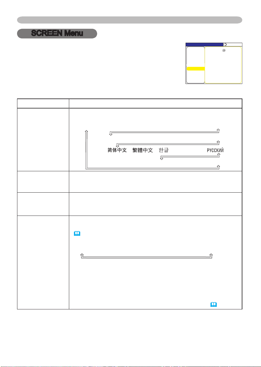
Multifunctional settings
SUOMI POLSKI TÜRKÇE
ENGLISH FRANÇAIS DEUTSCH ESPAÑOL ITALIANO
NORSK NEDERLANDS PORTUGUÊS 日本語
SVENSKA
MENU [RGB]
IMAGE
SETUP
PICTURE
INPUT
OPTION
EASY MENU
SCREEN
:SELECT
LANGUAGE ENGLISH
MENU POSITION
START UP ORIGINAL
OSD BRIGHT 5
MyScreen
MyScreen Lock TURN OFF
MESSAGE TURN ON
BLANK BLACK
VIDEO Qlty.
NETWORK
SCREEN Menu
With the SCREEN menu, items shown in the table below
can be performed.
Select an item using the cursor buttons ▲/▼ on the
projector or remote control, and press the cursor button ►
on the projector or remote control, or the ENTER button on
the remote control to progress. Then perform it referring to
the following table.
Item Description
Using the buttons ▲/▼ switches the OSD (On Screen Display)
language.
LANGUAGE
Using the buttons ◄/►/▲/▼ adjusts the menu position.
MENU POSITION
OSD BRIGHT
BLANK
To quit the operation, press the MENU button on the remote control
or keep no operation for 10 seconds.
Using the buttons ▲/▼ switches the brightness level of the OSD (On
Screen Display).
BRIGHT
DARK
Using the buttons ▲/▼ switches the mode for the blank screen.
The blank screen is the screen for the temporarily blanking feature
(21). It is displayed by pressing the BLANK button on the remote
control.
MyScreen
ORIGINAL
BLUE WHITE BLACK
MyScreen is the screen you can register a desired screen.
ORIGINAL screen is the existing standard screen.
and BLACK are non-patterned (plain) screens in each color.
• To avoid remaining as an afterimage, the MyScreen and the
ORIGINAL screens will change to the BLACK screen after several
minutes.
• For the MyScreen, please refer to the item MyScreen (36).
BLUE, WHITE
35
Page 48
36
Multifunctional settings
SCREEN Menu (continued)
Item Description
Using the buttons ▲/▼ switches the mode for the start up screen.
The start up screen is the screen displayed when no signal or an
unsuitable signal is detected.
MyScreen
MyScreen is the screen you can register a desired screen.
START UP
My Screen
My Screen Lock
ORIGINAL screen is the existing standard screen. When the TURN
OFF is selected, the BLACK screen is used.
• To avoid remaining as an afterimage, the MyScreen and the
ORIGINAL screens will change to the BLANK screen after several
minutes. If also the BLANK screen is the MyScreen or ORIGINAL, it
will change to the BLACK screen.
• For the MyScreen, please refer to the item MyScreen
About the BLANK screen, please refer to the item BLANK (35).
This item functions for capturing the MyScreen of the blank screen
and the start up screen. Please execute displaying the input
including the picture you want to capture.
1. Selecting this item displays a dialog titled “MyScreen”. It will ask
you if you start capturing the picture from the current screen.
Please wait for the target picture to be displayed, and press the
ENTER button on the remote control when the picture is display.
The picture will freeze and the frame for capturing appears.
To stop performing, press the RESET or ESC button on the
remote control.
2. Using the buttons ◄/►/▲/▼ adjust the frame position. Please
move the frame to the position of the picture which you want to
use.
To start registration, press the ENTER button on the remote
control.
To restore the screen and return to the previous dialog, press the
RESET or ESC button on the remote control.
Registration takes several minutes. When the registration is
completed, the registered screen and the message “MyScreen
registration is finished.” are displayed for several seconds. If the
registration failed, the message “A capturing error has occurred.
Please try again.” is displayed.
Using the buttons ▲/▼ turns on/off the MyScreen lock function.
TURN ON
When the TURN ON is selected, the item MyScreen cannot be
performed. Use this function for protecting the current MyScreen.
ORIGINAL TURN OFF
TURN OFF
below
.
Page 49
SCREEN Menu (continued)
Item Description
Using the buttons ▲/▼ turns on/off the message function.
TURN ON
When the TURN ON is selected, the following message function
works.
MESSAGE
“AUTO IN PROGRESS” while automatically adjusting
”NO INPUT IS DETECTED”
”SYNC IS OUT OF RANGE”
"Searching….” while searching for the input
”Detecting….” while an input signal is detected
The indication of the input signal by changing
The indication of the aspect ration by changing
TURN OFF
Multifunctional settings
37
Page 50
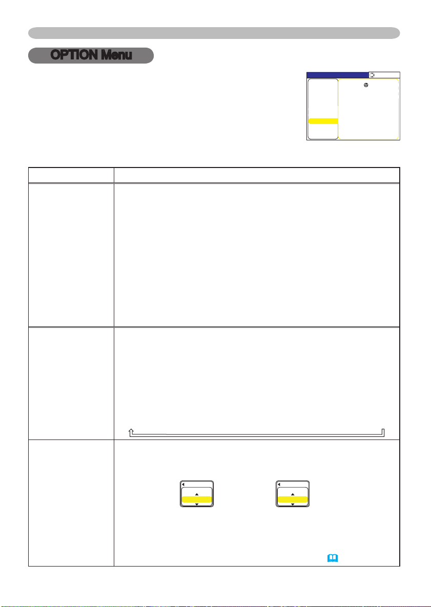
38
Multifunctional settings
AUTO OFF
ENABL
E
1
AUTO OFF
DISABLE
0
MENU [RGB]
VIDEO Qlty.
SETUP
PICTURE
INPUT
OPTION
EASY MENU
SCREEN
:SELECT
AUTO OFF 0
LAMP TIME 0
FILTER TIME 0
ONETOUCH
AUTO SEARCH TURN OFF
IMAGE
NETWORK
SERVICE
OPTION Menu
With the OPTION menu, items shown in the table below
can be performed.
Select an item using the cursor buttons ▲/▼ on the
projector or remote co
on the projector or remote control, or the ENTER button on
the remote control to progress, except for the items LAMP
TIME and FILTER TIME. Then perform it referring to the
following table.
Item Description
ONE TOUCH
AUTO SEARCH
ntrol, and press the cursor button ►
Using the buttons ▲/▼ turns on/off the automatic keystone
correction function.
TURN ON
You can automatically correct vertical keystone distortion
corresponding to the angle (forward/backward tilt) at which the unit
is set up. This function works with ONE TOUCH operation.
• If the projection screen is inclined, or if the projector is angled
downwards, it may not be possible to make the correct adjustment
when V: INVERT or H&V: INVERT is selected under the MIRROR
item of the SETUP menu.
• When the zoom adjustment is set to the TELE side, automatic
correction may be excessive. The automatic correction function
should be used with zoom set to WIDE whenever possible.
Using the buttons ▲/▼ turns on/off the automatic signal search
function.
TURN ON
This function works with INPUT, RGB, and VIDEO buttons.
When the TURN ON is selected, detecting no signal automatically
cycles through input ports in order of following. The search is
started from the current port. Then when an input is found, the
projector will stop searching and display the image.
RGB IN1 RGB IN2 DVI-D COMPONENT VIDEO S-VIDEO VIDEO
Using the buttons ▲/▼ adjusts the time to count down to
automatically turn the projector off
Long (max. 99 minutes) Short (min. 0 minute = DISABLE)
TURN OFF
TURN OFF
.
AUTO OFF
When the time is set to 0, the projector is not turned off automatically.
When the time is set to 1 to 99, and when the passed time with
a no-signal or an unsuitable signal reaches at the set time, the
projector lamp will go off and the power indicator begins blinking.
Please refer to the section “Turning off the power” (16).
Page 51
OPTION Menu (continued)
Item Description
The lamp time is the time counted after the last resetting. It is
shown in the OPTION menu as the use time of the lamp.
Pressing the RESET button on the remote control
of the projector for about 3 seconds displays a dialog. To reset the
LAMP TIME
FILTER TIME
SERVICE
lamp time, select the RESET using the button ▲.
RESET
• Please reset the lamp time only when you have replaced the lamp,
for correct messages about the lamp.
• About the lamp replacement, see the section "Lamp" (44, 45).
The filter time is the time counted after the last resetting. It is shown
in the OPTION menu as the use time of the air filter.
Pressing the RESET button on the remote control
of the projector for about 3 seconds displays a dialog. To reset the
filter time, select the RESET using the button ▲.
RESET CANCEL
• Please reset the filter time only when you have cleaned or
replaced the air filter, for correct messages about the air filter.
• About the caring the air filter, see the section "Air filter" (46).
Selecting this item displays the SERVICE menu.
Select an item using the buttons ▲/▼, and press the button ► or
the ENTER button on the remote control to progress.
FAN SPEED
FAN SPEED
Using the buttons ▲/▼ switches the rotation speed of the cooling
fans. The HIGH is the mode for use at highlands etc.
projector is noisier when the HIGH is selected.
HIGH NORMAL
AUTO ADJUST
Using the buttons ▲/▼ enable/disable the automatic adjustment.
ENABLE DISABLE
GHOST
1. Select a color element of ghost using the buttons
2.
Adjust the selected element using the buttons ▲/▼ to disappear ghost.
FACTORY RESET
Selecting RESET using the button ▲ performs this function.
function, all the items in all of menu will collectively return to the
initial setting. Note that the items LAMP TIME, FILTER TIME and
LANGUAGE are not reset.
RESET
Multifunctional settings
or the button ►
CANCEL
or the button ►
AUTO ADJUST GHOST FACTORY RESET
Note that the
◄/►.
CANCEL
By this
39
Page 52
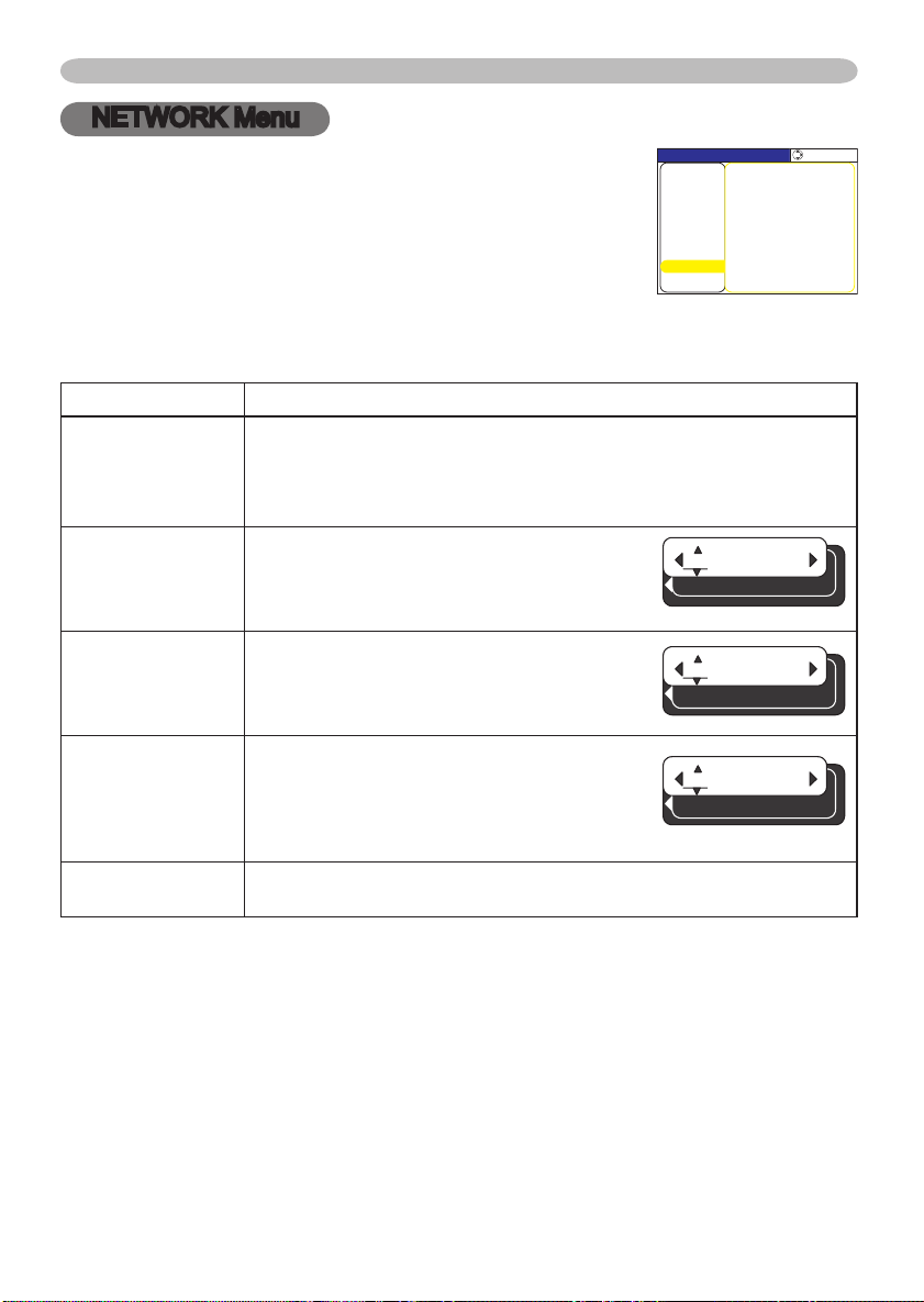
40
Multifunctional settings
MENU [RGB]
IMAGE
SETUP
PICTURE
INPUT
OPTION
SCREEN
:SELECT
VIDEO Qlty.
EASY MENU
IP ADDRESS
SUBNET MASK
INFORMATION
DHCP TURN OFF
DEFAULT GATEWAY
NETWORK
192. 168. 24
IP ADDRESS
1.
255. 255. 1
SUBNET MASK
255.
255. 255. 0
DEFAULT GATEWAY
255.
NETWORK Menu
With the NETWORK menu, items shown in the table below
can be performed.
Select an item using the cursor buttons ▲/▼ on the
projector or remote co
on the projector or remote control, or the ENTER button on
the remote control to progress. Then perform it referring to
the following table.
Make your Network settings by manual operation as following the
dialog box.
Item Description
DHCP
IP ADDRESS
SUBNET MASK
DEFAULT
GATEWAY
INFORMATION
ntrol, and press the cursor button ►
Using the buttons ▲/▼ turns on/off the DHCP function.
TURN ON
If your network doesn’t support the DHCP function, select the TURN
OFF.
Enter the IP address of the projector using
the ◄/►/▲/▼ buttons.
This menu is available only when the item of
the DHCP is set to TURN OFF.
Enter the SUBNET MASK of your
NETWORK using the ◄/►/▲/▼ buttons.
This menu is available only when the item of
the DHCP is set to TURN OFF.
Enter the DEFAULT GATEWAY. This is the
address of the device as gateway to an
outer network.
This menu is available only when the item of
the DHCP is set to TURN OFF.
Selecting this item shows the information about the current network
setting of the projector.
TURN OFF
Page 53
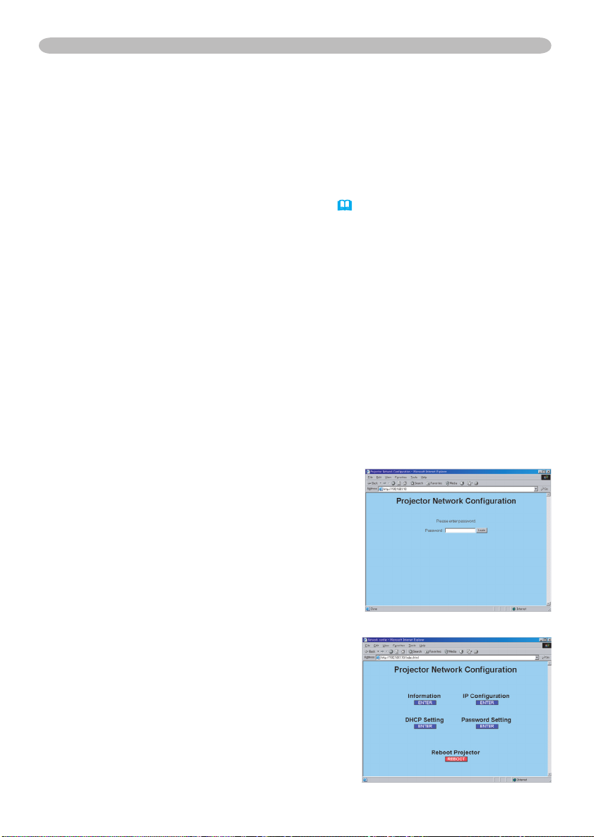
Multifunctional settings
NETWORK Menu (continued)
This projector provides the NETWORK function. When you start to use this function, please
consult your dealer for further information.
To start, connect the LAN port to a gateway device via a CAT-5 cable, then set up the
projector according to the Network environment in which you use it.
When your network enables the DHCP function
ou can set automatically, if you set the DHCP function to TURN ON using the NETWORK
Y
menu. Please refer to the section NETWORK menu (40).
When your network doesn't support the DHCP function or when
you use a fixed address even if your network can support the
DHCP function
Please set the IP address, the subnet mask, the default gateway and the DHCP using the
NETWORK menu. At first, set the DHCP function to TURN OFF.
It is also possible to configure the projector's network settings using a Web browser (Internet
Explorer 5.0 or higher; Netscape 6.2 or higher) on a computer connected to the network.
When using a Web browser to configure the projector's network settings, password access
is required. However, since a password is not configured when the product is shipped from
the factory, if a password has not been configured, then you can simply click on Login
without entering a password to access the Projector Network Configuration dialog.
To configure the settings using a Web browser, proceed as follows:
ex. Case of IP Address = 192.168.1.10
nter http://192.168.1.10 into the Web browser's
E
1.
address field.
Once Screen 1 is displayed (as shown on the
2.
right), enter the password and then click on
"Login".
Once Screen 2 is displayed (as shown on the
3.
right), select the desired item by clicking the
corresponding ENTER button.
Information
Allows you to confirm the current network settings.
(Screen 3)
IP Configuration
Allows you to configure IP address, subnet mask and
default gateway if DHCP is disabled. (Screen 4)
DHCP Setting
Allows you to enable or disable DHCP. (Screen 5)
Password Setting
Allows you to change the login password. (Screen 6)
Screen 1
Screen 2
41
Page 54
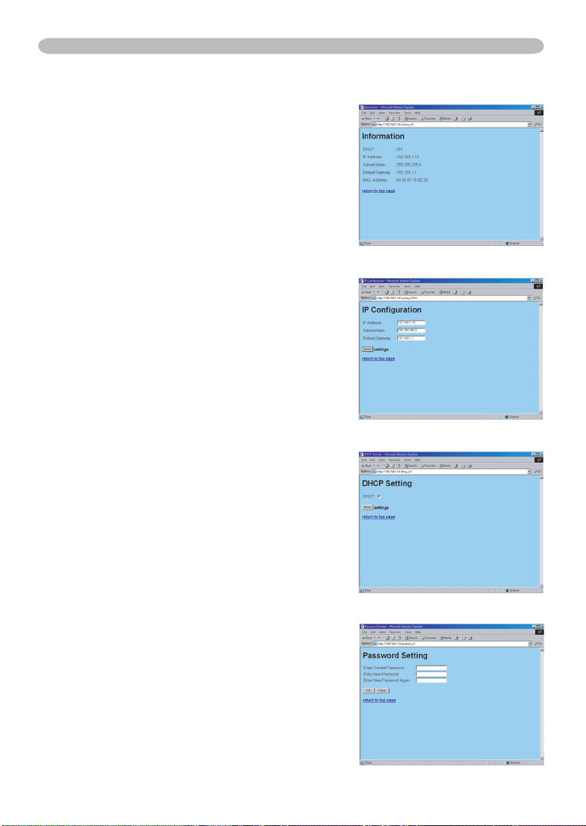
42
Multifunctional settings
NETWORK Menu (continued)
Information
1) Allows you to confirm the current network settings of
the projector.
2) Click on "return to top page" to return to Screen 2.
IP Configuration
Allows you to configure the IP address, subnet mask
and default gateway if DHCP is disable.
1) Enter the IP address.
2) Enter the subnet mask.
3) Enter the default gateway.
4) Click on "Write".
5) Click on "return to top page" to return to Screen 2.
DHCP Setting
1) Check the "DHCP" box to enable DHCP or uncheck
the "DHCP" box to disable DHCP.
2) Click on "Write".
3) Click on "return to top page" to return to Screen 2.
Screen 3
Screen 4
Screen 5
Password Setting
1) Enter the current password.
2) Enter the new password.
3) Enter the new password again.
4) Click on "OK".
5) Click on "return to top page" to return to Screen 2.
• The password is case sensitive and can be up to 16
single-byte alphanumeric characters in length.
Screen 6
Page 55

Multifunctional settings
NETWORK Menu (continued)
If you modified the IP configuration or the DHCP setting, click on "Reboot" in Screen 2
4.
to have the settings take effect.
Close the Web browser to end the configuration session.
5.
• If the Projector Network Configuration dialog is accessed by more than one
NOTE
computer at the same time, the last computer to login retains the authority to modify the
settings. If you wish to make changes using a computer that logged on earlier, you will
need to login again to regain authority.
• Except for the login screen, all of the screens will timeout after 10 minutes of no
operation. Should this occur, you will need to login again to modify the settings.
• The 10-minute timeout remains in effect even if you close the Web browser and end
the configuration session. Therefore, if you try to reestablish a session from the same
computer before the 10-minute timeout occurs, the login screen will not reappear.
However, if you reboot or if you login from another PC, the 10-minute timeout will no
longer be in effect.
43
Page 56
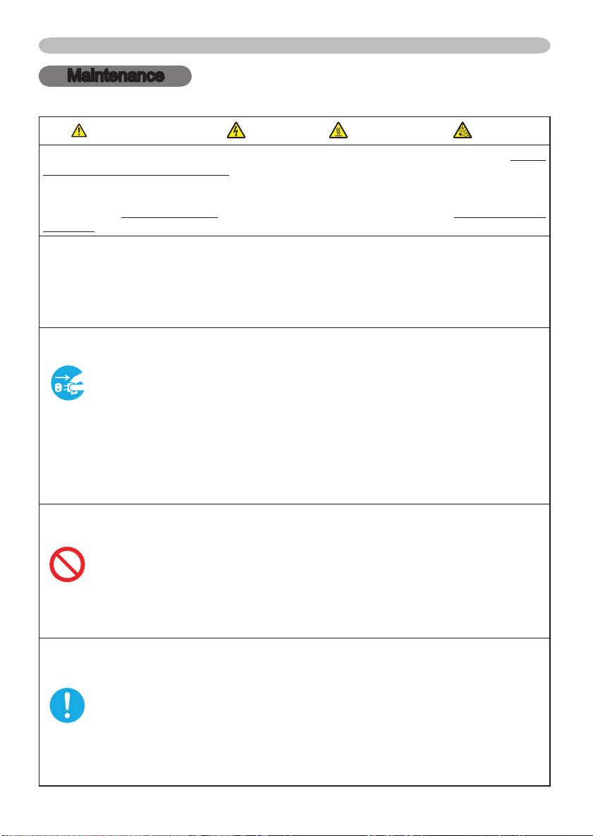
44
Maintenance
Maintenance
Lamp
WARNING
HIGH VOLTAGE
HIGH TEMPERATURE
HIGH PRESSURE
►The projector uses a high-pressure mercury glass lamp. The lamp can break
with a loud bang, or burn out, if jolted or scratched, handled while hot, or worn
over time. Note that each lamp has a different lifetime, and some may burst or
burn out soon after you start using them. In addition, when the bulb bursts, it is
possible for shards of glass to fly into the lamp housing, and for gas containing
mercury to escape from the projector’s vent holes.
►About disposal of a lamp • This product contains a mercury lamp; do not
put in trash. Dispose of in accord with environmental laws.
For lamp recycling, go to www.lamprecycle.org. (in the US)
For product disposal, contact your local government agency or www.eiae.org (in
the US) or www.epsc.ca (in Canada).
For more information, call your dealer.
• If the lamp should break (it will make a loud bang when it does),
unplug the power cord from the outlet, and make sure to request a
replacement lamp from your local dealer. Note that shards of glass
could damage the projector’s internals, or cause injury during handling,
so please do not try to clean the projector or replace the lamp yourself.
Disconnect
the plug
from the
• If the lamp should break (it will make a loud bang when it does),
ventilate the room well, and make sure not to breathe the gas that
comes out of the projector vents, or get it in your eyes or mouth.
power
• Before replacing the lamp, turn the projector off and unplug the power
outlet
cord, then wait at least 45 minutes for the lamp to cool sufficiently.
Handling the lamp while hot can cause burns, as well as damaging the
lamp.
• Never unscrew except the appointed (marked by an arrow) screws.
• Do not open the lamp cover while the projector is suspended from
above. This is dangerous, since if the lamp’s bulb has broken, the
shards will fall out when the cover is opened. In addition, working in
high places is dangerous, so ask your local dealer to have the lamp
replaced even if the bulb is not broken.
• Do not use the projector with the lamp cover removed. At the lamp
replacing, make sure that the screws are screwed in firmly. Loose
screws could result in damage or injury.
• Use only the lamp of the specified type.
• If the lamp breaks soon after the first time it is used, it is possible
that there are electrical problems elsewhere besides the lamp. If this
happens, contact your local dealer or a service representative.
•
Handle with care: jolting or scratching could cause the lamp bulb to burst during use.
• If the indicators or a message prompts you to replace the lamp (see
the section "Related Messages" and "Regarding the indicator Lamps"),
replace the lamp as soon as possible. Using the lamp for long periods
of time, or past the replacement date, could cause it to burst. Do not
use old (used) lamps; this is a cause of breakage.
Page 57
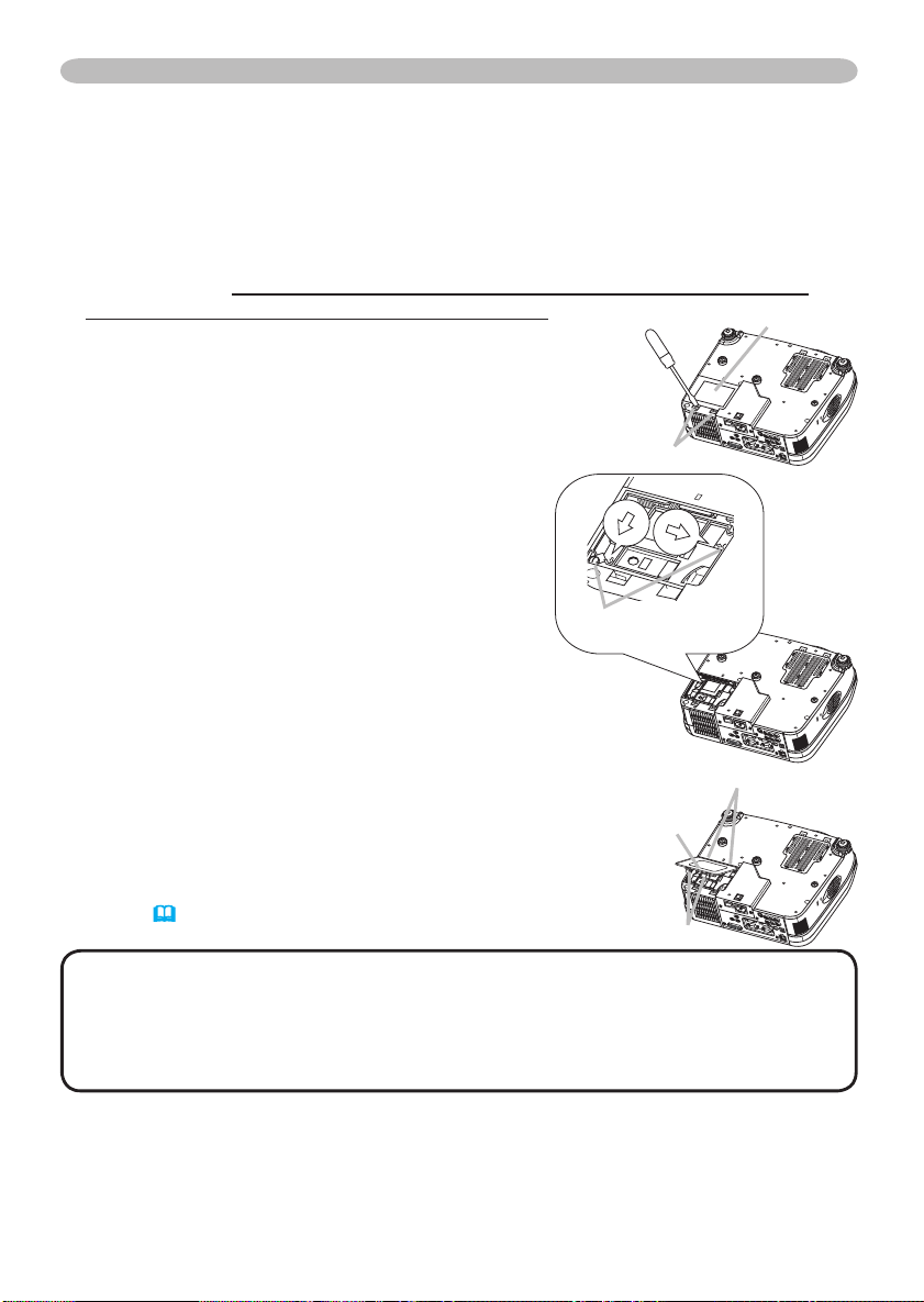
Maintenance
Lamp (continued)
When the indicators or a message prompts you to replace the lamp, replace the
lamp as soon as possible.
Turn the projector off, and unplug the power cord. Allow the lamp to cool for
1.
at least 45 minutes.
To prepare a new lamp, contact your dealer and tell the lamp type number
2.
= 456-8915. If the projector is mounted on the ceiling, or if the lamp has
broken, also ask the dealer to replace the lamp.
In the case of replacement by yourself,
After making sure that the projector has
3.
cooled adequately, slowly turn over the
projector, so that the bottom is facing up.
Please unhook the claws of the lamp cover
4.
using a minus screwdriver or similar, and
remove the lamp cover.
Loosen the 2 screws (marked by arrow) of
5.
the lamp, and slowly pick up the lamp by the
handles.
Insert the new lamp, and retighten firmly two
6.
screws that are loosened in the previous
process to lock it in place.
Interlocking the 2 tabs of the lamp cover to
7.
the projector, position the lamp cover on the
projector. Then push the center point of two
claws to fix the lamp cover.
Slowly turn the projector so that the top is
8.
facing up.
Turn the projector on, and reset the lamp time
9.
using the LAMP TIME function of OPTION
(39)
menu
.
Claws
Screws marked
by arrow
Center point
of claws
Claws
Lamp cover
Tabs
NOTE • When the lamp has been replaced after the message of "THE
POWER WILL TURN OFF AFTER 0hr." is displayed, complete the following
operation within 10 minutes of switching power on.
• Incorrectly resetting of the lamp timer (resetting without replacement, or
neglect of resetting after replacement) will result in incorrect message functions.
45
Page 58
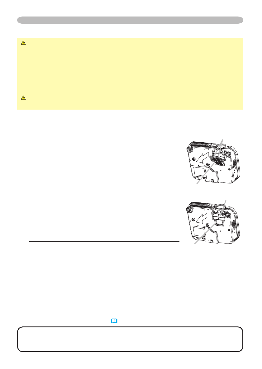
46
Maintenance
Air filter
WARNING ►Before caring, make sure the power switch is off and the
power cable is not plugged in, then allow the projector to cool sufficiently. The
care in a high temperature state of the projector could cause a burn and/or
malfunction to the projector.
►Use only the air filter of the specified type. Do not use the projector with the
air filter and filter cover removed.
►Avoid wetting the projector or inserting liquids in the projector. It could result
in a fire, an electric shock, and/or malfunction to the projector
CAUTION ►Please replace the air filter when it is damaged or too soiled,
and also when you replace the lamp.
When the indicators or a message prompts you to clean the air filter, clean the air filter as
soon as possible. If the air filter becomes clogged by dust or the like, internal temperatures
rise and the power may be automatically turned off for malfunction prevention.
Turn the projector off, and unplug the power cord.
1.
Allow the projector to cool for at least 45 minutes. And
prepare a vacuum cleaner.
After making sure that the projector is cool adequately,
2.
slowly turn the projector so that the lens-side is facing
up. Please be careful for a projector not to fall. While the
projector is placed lens-side up, hold the projector.
Unhooking the filter cover’s claws, pull the filter cover
3.
in the direction of the arrow to remove it.
Holding the air filter’s knob, pull the air filter off.
4.
Apply a vacuum cleaner to the vent of the projector for the
5.
air filter. And then slowly turn the projector bottom up.
Apply a vacuum cleaner to the air filter and filter cover.
6.
Please replace the air filter when it is damaged or too soiled.
To prepare a new air filter, contact your dealer and tell the air
filter type number =
An air filter of specified type will come even with the replacement lamp for this projector.
Position the cleaned air filter or a new air filter into place, and push the points
7.
of "PUSH" word with claws to fix the air filter.
Replace the filter cover and snap it back into place.
8.
NJ20642.
.
Filter cover’s claws
Filter cover
Air filter’s knob
Air filter
Slowly turn the projector so that the top is facing up.
9.
Turn the projector on, and reset the filter time using the FILTER TIME
10.
function of OPTION menu
NOTE • Incorrectly resetting of the filter timer (resetting without replacement,
or neglect of resetting after replacement) will result in incorrect message
functions.
(39)
.
Page 59

Maintenance
Other care
WARNING ►Before caring, make sure the power switch is off and the
power cable is not plugged in, and then allow the projector to cool sufficiently.
The care in a high temperature state of the projector could cause a burn and/or
malfunction to the projector.
►Never try to care for the inside of the projector personally. Doing is so
dangerous.
►Avoid wetting the projector or inserting liquids in the projector. It could result
in a fire, an electric shock, and/or malfunction to the projector.
• Don’t put a container containing water, cleaner or chemicals near the
projector.
• Don’t use aerosols or sprays.
CAUTION ►Please take right care of the projector according to the
following. Incorrect care could cause not only an injury but adverse influence
such as discoloration, peeling paint, etc.
►Do not use cleaner or chemicals other than those listed below.
►Do not polish or wipe with hard objects.
Inside of the projector
In order to ensure the safe use of your projector, please have it cleaned and
inspected by your dealer about once every 2 years.
Caring for the lens
If the lens is flawed, soiled or fogged, it could cause deterioration of display
quality. Please take care of the lens, being cautious of the handling.
Turn the projector off, and unplug the power cord. Allow the projector to cool
1.
sufficiently.
After making sure that the projector is cool adequately, lightly wipe the lens
2.
with a commercially available lens-cleaning wipe. Do not touch the lens
directly with your hand.
Caring for the cabinet and remote control
Incorrect care could have adverse influence such as discoloration, peeling paint,
etc.
Turn the projector off, and unplug the power cord. Allow the projector to cool
1.
sufficiently.
After making sure that the projector is cool adequately, lightly wipe with gauze
2.
or a soft cloth.
If soiling is severe, dip soft cloth in water or a neutral cleaner dilute in water,
and wipe lightly after wringing well. Then, wipe lightly with a soft, dry cloth.
47
Page 60
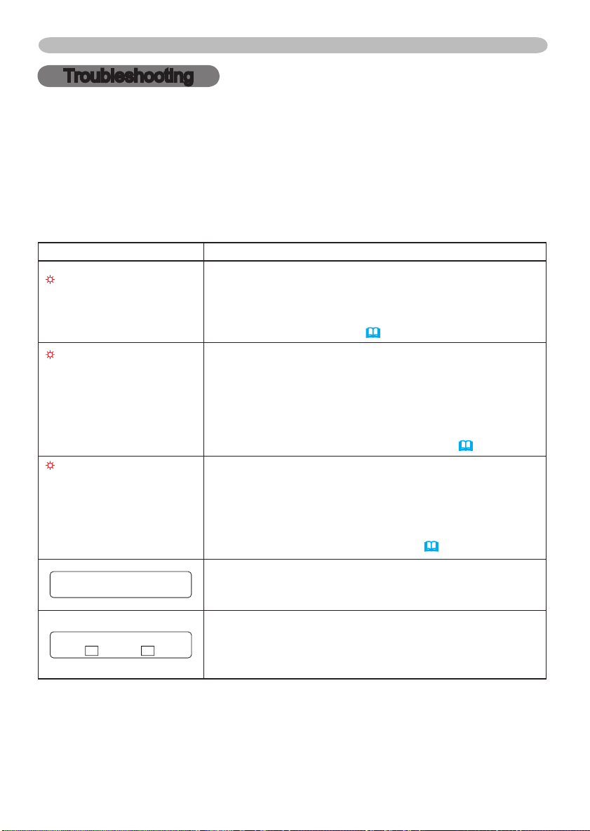
48
Troubleshooting
NO INPUT IS DETECTED
ON ***
SYNC IS OUT OF RANGE
ON *** fH *****kHz fV *****Hz
Troubleshooting
Related messages
When the unit's power is on, messages such as those shown below may be
displayed. When any such message is displayed on the screen, please respond
as described below. If the same message is displayed after the treatment, or if a
message other than the following appears, please contact your dealer or service
company.
Although these messages will be automatically disappeared around several
minutes, it will be reappeared every time the power is turned on.
Message Description
CHANGE THE LAMP
AFTER REPLACING LAMP,
RESET THE LAMP TIMER.
CHANGE THE LAMP
AFTER REPLACING LAMP,
RESET THE LAMP TIMER.
THE POWER WILL TURN OFF
AFTER ** hr.
CHANGE THE LAMP
AFTER REPLACING LAMP,
RESET THE LAMP TIMER.
THE POWER WILL TURN OFF
AFTER 0 hr.
The time the lamp timer has counted is approaching
2000 hours.
Preparation of a new lamp, and an early lamp change is
recommended. After you have change the lamp, please be
sure to reset the lamp timer(39).
The time the lamp timer has counted is approaching
2000 hours, so a lamp change within ** hours is
recommended.
When lamp usage reaches 2000 hours, the power will
automatically be turned off. Please change the lamp by
referring to the section “Lamp”. After you have changed the
lamp, please be sure to reset the lamp timer(39).
As the time the lamp timer has counted has reached
2000 hours, the power will soon be automatically
turned off.
Please immediately turn the power off, and change the lamp
by referring to the section “Lamp”. After changing the lamp,
please be sure to reset the lamp timer(39).
There is no input signal.
Please confirm the signal input connection, and the status
of the signal source.
The horizontal or vertical wavelength of the inputted
signal is outside of the response parameters of this unit.
Please confirm the specs for this unit or the signal source
specs.
Page 61
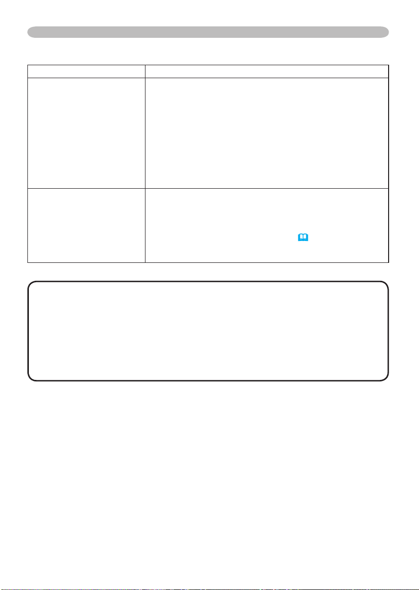
Troubleshooting
Related messages (continued)
Message Description
The internal portion temperature is rising.
Please turn the power OFF, and allow the unit to cool down
at least 20 minutes. After having confirmed the following
items, please turn the power ON again.
CHECK THE AIR FLOW
CLEAN THE AIR FILTER
POWER OFF FIRST,
THEN CLEAN THE AIR
FILTER.
AFTER CLEANING THE AIR
FILTER,
RESET THE FILTER TIMER.
• Is there blockage of the air passage aperture?
• Is the air filter dirty?
• Does the peripheral temperature exceed 35°C?
If the same indication is displayed after the treatment,
please set the HIGH at the FAN SPEED of the item
SERVICE of the OPTION menu.
A note of precaution when cleaning the air filter.
Please immediately turn the power OFF, and clean or
change the air filter by referring to the “Air Filter” section of
this manual. After you have cleaned or changed the air filter,
please be sure to reset the filter timer
(39).
NOTE • A lamp has a finite product life. Lamps are characterized by the
fact that, after long hours of usage, a lamp will no longer light up, or the lamp
will break or burst, etc. This projector is equipped with an automatic shut-down
function, such that the power will automatically be turned off when lamp usage
time has reached 2000 hours. Please be aware, however, that among lamp
types, there are major differences in product lifetimes; a lamp may thus fail to
light even prior to the functioning of the automatic shut-down function of this
projector.
49
Page 62
50
Troubleshooting
Regarding the indicator lamps
Lighting and flashing of the POWER indicator, the LAMP indicator, and the TEMP
indicator have the meanings as described in the table below. Please respond
in accordance with the instructions within the table. If the same indication is
displayed after the treatment, or if an indication other than the following is
displayed, please contact your dealer or service company.
POWER
indicator
Lighting
In Orange
Blinking
In Green
Lighting
In Green
Blinking
In Orange
Blinking
In Red
Blinking
In Red
or
Lighting
In Red
Blinking
In Red
or
Lighting
In Red
LAMP
indicator
Turned
off
Turned
off
Turned
off
Turned
off
(discretionary)
Lighting
In Red
Blinking
In Red
TEMP
indicator
Turned
off
Turned
off
Turned
off
Turned
off
(discre-
tionary)
Turned
off
Turned
off
Description
The projector is in a standby state.
Please refer to the section “Power On/Off”.
The projector is warming up.
Please wait.
The projector is in an on state.
Ordinary operations may be performed.
The projector is cooling down.
Please wait.
The projector is cooling down. A certain error
has been detected.
Please wait until the POWER indicator finishes blink,
and then perform the proper response measure using
the item descriptions below as reference.
The lamp does not light, and there is a
possibility that interior portion has become
heated.
Please turn the power off, and allow the unit to cool
down at least 20 minutes. After the projector has
sufficiently cooled down, please make confirmation of
the following items, and then turn the power on again.
• Is there blockage of the air passage aperture?
• Is the air filter dirty?
• Does the peripheral temperature exceed 35°C?
If the same indication is displayed after the treatment,
please change the lamp by referring to the section
“Lamp”.
The lamp cover has not been properly fixed
(attached).
Please turn the power off, and allow the unit to cool
down at least 45 minutes. After the projector has
sufficiently cooled down, please make confirmation
of the attachment state of the lamp cover. After
performing any needed maintenance, turn the power
on again. If the same indication is displayed after
the treatment, please contact your dealer or service
company.
Page 63
Regarding the indicator lamps (continued)
Troubleshooting
POWER
indicator
Blinking
In Red
or
Lighting
In Red
Blinking
In Red
or
Lighting
In Red
Lighting
In Green
Lighting
In Green
LAMP
indicator
Turned
off
Turned
off
Alternative
blinking in Red
Simultaneous
blinking in Red
TEMP
indicator
Blinking
In Red
Lighting
In Red
Description
The cooling fan is not operating.
Please turn the power off, and allow the unit to cool
down at least 20 minutes. After the projector has
sufficiently cooled down, please make confirmation
that no foreign matter has become caught in the fan,
etc., and then turn the power on again.
If the same indication is displayed after the treatment,
please contact your dealer or service company.
There is a possibility that the interior portion
has become heated.
Please turn the power off, and allow the unit to cool
down at least 20 minutes. After the projector has
sufficiently cooled down, please make confirmation of
the following items, and then turn the power on again.
• Is there blockage of the air passage aperture?
• Is the air filter dirty?
• Does the peripheral temperature exceed 35°C?
If the same indication is displayed after the treatment,
please set the HIGH at the FAN SPEED of the item
SERVICE of the OPTION menu.
There is a possibility that the interior portion
has become overcooled.
Please use the unit within the usage temperature
parameters (5°C to 35°C). After the treatment, resent
the power to ON.
It is time to clean the air filter.
Please immediately turn the power OFF, and clean
or change the air filter by referring to the section “Air
Filter”. After cleaning or changed the air filter
be sure to reset the filter timer. After the treatment,
resent the power to ON.
, please
NOTE • When the interior portion has become overheated, for safety
purposes, the power source is automatically turned off, and the indicator lamps
may also be turned off. In such a case, press the “
” (OFF) side of the power
switch, and wait at least 45 minutes. After the projector has sufficiently cooled
down, please make confirmation of the attachment state of the lamp and lamp
cover, and then turn the power on again.
51
Page 64
52
Troubleshooting
Phenomena that may easily be mistaken for machine defects
WARNING ►Never use the projector if abnormal operations such as
smoke, strange odor, excessive sound, damaged casing or elements or cables,
penetration of liquids or foreign matter, etc. should occur. In such cases,
immediately turn off the power switch and then disconnect the power plug from
the power outlet. After making sure that the smoke or odor has stopped, contact
your dealer or service company.
Before requesting repair, please check in accordance with the following chart.
1.
This operation sometimes resolves your problem.
If the situation cannot be corrected,
The projector’s microprocessor may need to be reset. Please push the
2.
Restart switch by using a cocktail stick or similar and the projector will restart.
Some setting may be wrong. Please use the FACTORY RESET function of
3.
SERVICE menu in the OPTION menu
default.
Then, if the problem is not removed after maintenance, please contact your dealer
or service company.
(39)
to reset all settings to factory
Phenomenon Cases not involving a machine defect
The electrical power cord is not plugged in.
Correctly connect the power cord.
The power switch is not set to the on position.
Set the power switch to [ | ] (On).
The main power source has been interrupted during
operation such as by a power outage (blackout), etc.
Power does not
come on.
Please turn the power off, and allow the unit to cool down at
least 20 minutes. After the projector has sufficiently cooled
down, please turn the power on again.
Either there is no lamp and/or lamp cover, or either
of these has not been properly fixed.
Please turn the power off, and allow the unit to cool down at
least 45 minutes. After the projector has sufficiently cooled
down, please make confirmation of the attachment state of
the lamp and lamp cover, and then turn the power on again.
Reference
page
13
16
16
44, 45
Page 65
Troubleshooting
Phenomena that may easily be mistaken for machine defects (continued)
Phenomenon Cases not involving a machine defect
The lens cap is attached.
Remove the lens cap.
The signal cables are not correctly connected.
Correctly connect the connection cables.
No pictures are
displayed.
The brightness is adjusted to an extremely low level.
Adjust the BRIGHT to a higher level using the menu function
or the remote control.
The computer cannot detect the projector as a plug
and play monitor.
Make sure that the computer’s can detect a plug and play
monitor using other plug and play monitor.
Color settings are not correctly adjusted.
Colors have a
faded- out
appearance, or
Color tone is
poor.
Perform picture adjustments by changing the COLOR
COLOR, TINT and/or COLOR SPACE settings,
TEMP,
using the menu functions.
COLOR SPACE setting is not suitable.
Change the COLOR SPACE setting to AUTO, RGB,
SMPTE240, REC709 or REC601.
The brightness and/or contrast are adjusted to an
extremely low level.
Adjust the BRIGHT and/or CONTRAST settings to a higher
level using the menu function.
Pictures appear
dark.
The WHISPER function is working.
Select the NORMAL to the item WHISPER in the SETUP
menu.
The lamp is approaching the end of its product
lifetime.
Replace the lamp.
Either the focus and/or horizontal phase settings are
not properly.
Pictures appear
blurry.
Adjust the focus using the focus ring, and/or H PHASE
using the menu function.
The lens is dirty or misty.
Clean the lens by referring to the section “Caring for the
lens”.
Reference
page
4, 16
10
24, 26
10
24, 27,
32
32
24, 26
24, 34
44, 45
18, 29
47
NOTE • Although bright spots or dark spots may appear on the screen, this
is a unique characteristic of liquid crystal displays, and such do not constitute or
imply a machine defect.
53
Page 66
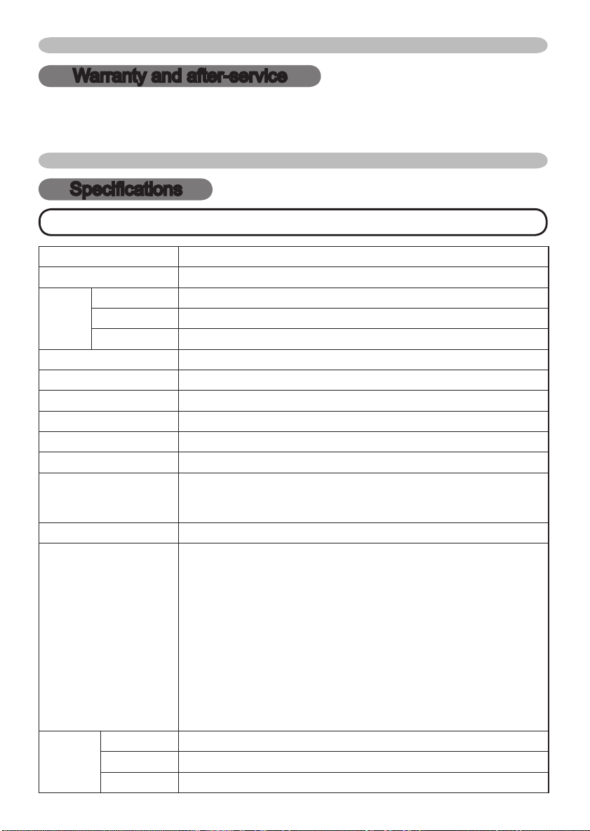
54
Warranty And After-Service
Warranty and after-service
If a problem occurs with the equipment, first refer to the “Troubleshooting” and run
through the suggested checks. If this does not resolve the problem, please contact your
dealer or the service company. They will tell you what warranty condition is applied.
Specifications
Specifications
NOTE • This specifications are subject to change without notice.
Item Specification
Product name Liquid crystal projector
Liquid
Crystal
panel
Lens Zoom lens F=1.7 ~ 2.0 f=24.4 ~ 29.2 mm
Lamp 230W UHB
Speaker 3W x 4
Power Supply AC100-120V/4.2A, AC220-240V/2.1A
Power Consumption 370W
Temperature range
Size
Weight (mass)
Ports
Optional
parts
Panel size 2.0 cm (0.79 type)
Drive system TFT active matrix
Pixels 786,432 pixels (1024 horizontal x 768 vertical)
5 ~ 35°C (Operating)
336 (W) x 95 (H) x 265 (D) mm
(Not including protruding parts)
• Please refer to the following figure.
3.9 kg
DIGITAL RGB input:
DVI-D ................................... 1
RGB input:
RGB IN1 ..D-sub 15pin mini x1
RGB IN2 ..D-sub 15pin mini x1
RGB output:
RGB OUT D-sub 15pin mini x1
Audio input:
AUDIO IN ........ Stereo mini x1
AUDIO IN L/R ............ RCA x2
Audio output:
AUDIO OUT ...
Lamp 456-8915
Air filter
Others • Please consult your dealer.
NJ20642
Stereo mini x1
Video input:
COMPONENT VIDEO
(Y,
CB/P
S-Video ................................ 1
Video ....................................
Communication port:
CONTROL ............D-sub 9pin x1
USB ....................... USB(B) x1
LAN ........................... RJ45 x1
Other port:
WIRED REMOTE ............... x1
DC OUT ...............................x1
B, CR/PR
) ...... RCA x3
1
Page 67
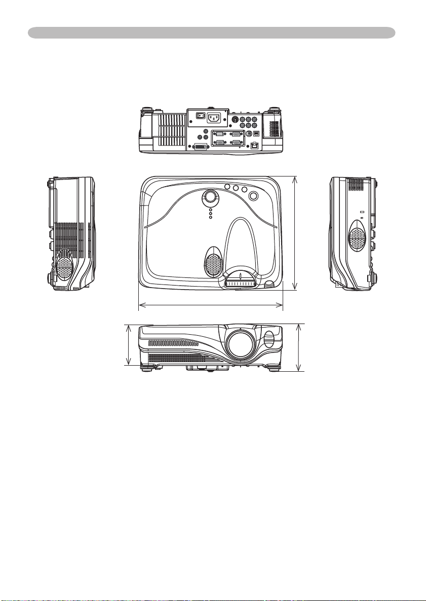
Specifications (continued)
Specifications
265mm
336mm
95mm
109mm
55
Page 68

Page 69
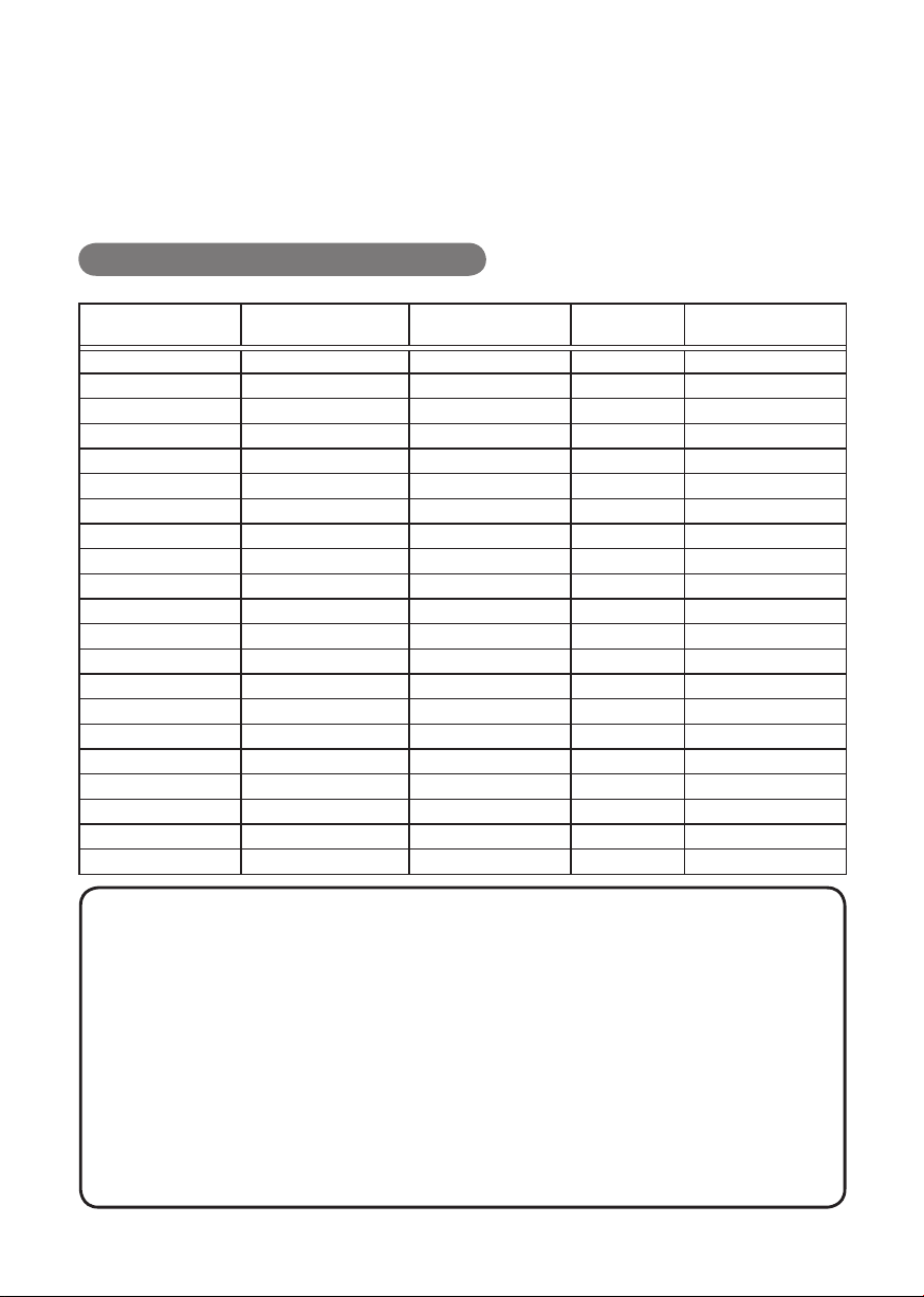
Projector
ImagePro 8915
User's Manual – Operating Guide
Technical
Example of computer signalExample of computer signal
Resolution (H x V) H. frequency (kHz) V. frequency (Hz) Rating Signal mode
720 x 400 37.9 85.0 VESA TEXT
640 x 480 31.5 59.9 VESA VGA (60Hz)
640 x 480 37.9 72.8 VESA VGA (72Hz)
640 x 480 37.5 75.0 VESA VGA (75Hz)
640 x 480 43.3 85.0 VESA VGA (75Hz)
800 x 600 35.2 56.3 VESA SVGA (56Hz)
800 x 600 37.9 60.3 VESA SVGA (60Hz)
800 x 600 48.1 72.2 VESA SVGA (72Hz)
800 x 600 46.9 75.0 VESA SVGA (75Hz)
800 x 600 53.7 85.1 VESA SVGA (85Hz)
832 x 624 49.7 74.5 Mac 16” mode
1024 x 768 48.4 60.0 VESA XGA (60Hz)
1024 x 768 56.5 70.1 VESA XGA (70Hz)
1024 x 768 60.0 75.0 VESA XGA (75Hz)
1024 x 768 68.7 85.0 VESA XGA (75Hz)
1152 x 864 67.5 75.0 VESA SXGA (75Hz)
1280 x 960 60.0 60.0 VESA SXGA (60Hz)
1280 x 1024 64.0 60.0 VESA SXGA (60Hz)
1280 x 1024 80.0 75.0 VESA SXGA (75Hz)
1280 x 1024 91.2 85.0 VESA SXGA (85Hz)
1600 x 1200 75.0 60.0 VESA UXGA (60Hz)
NOTE • Be sure to check jack type, signal level, timing and resolution
before connecting this projector to a computer.
• Some computers may have multiple display screen modes. Use of some of
these modes will not be possible with this projector.
• Depending on the input signal, full-size display may not be possible in some
cases. Refer to the number of display pixels above.
• Although the projector can display signals with resolution up to UXGA
(1600x1200), the signal will be converted to the projector’s panel resolution
before being displayed. The best display performance will be achieved if the
resolutions of the input signal and projector panel are identical.
• Automatically adjustment may not function correctly with some input signals.
• The image may not be displayed correctly when the input sync signal is a
composite sync or a sync on G.
1
Page 70
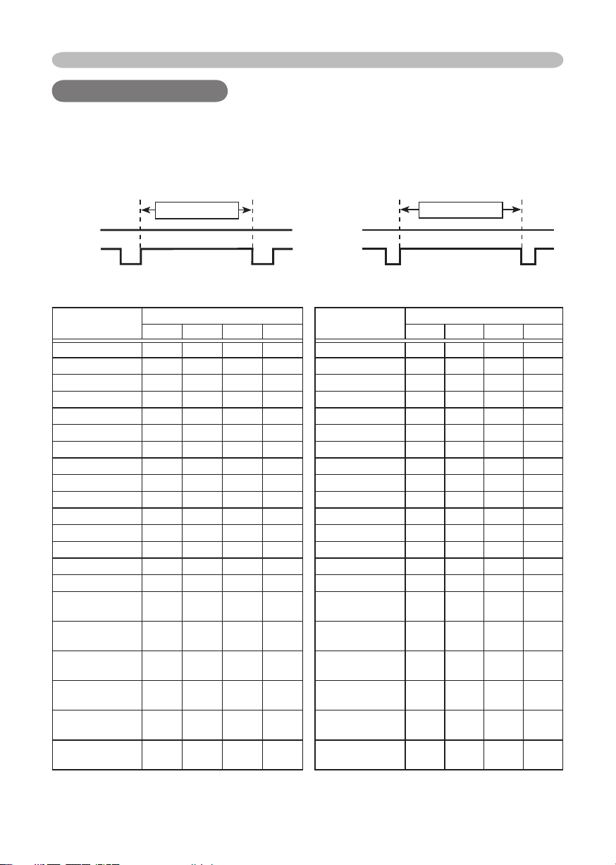
Example of computer signal
Initial set signals
Initial set signals
The following signals are used for the initial settings. The signal timing of some
computer models may be different. In such case, adjust the items V POSITION
and H POSITION in the IMAGE menu.
Data Data
H. Sync. V. Sync.
Sync (A) Sync (a)
Mac 16" mode 1.1 3.9 14.5 0.6 Mac 16" mode 3 39 624 1
Back porch (B) Front porch (D) Back porch (b) Front porch (d)
Display interval (C)
Computer/
Signal
TEXT 2.0 3.0 20.3 1.0 TEXT 3 42 400 1
VGA (60Hz) 3.8 1.9 25.4 0.6 VGA (60Hz) 2 33 480 10
VGA (72Hz) 1.3 3.8 20.3 1.0 VGA (72Hz) 3 28 480 9
VGA (75Hz) 2.0 3.8 20.3 0.5 VGA (75Hz) 3 16 480 1
VGA (85Hz) 1.6 2.2 17.8 1.6 VGA (85Hz) 3 25 480 1
SVGA (56Hz) 2.0 3.6 22.2 0.7 SVGA (56Hz) 2 22 600 1
SVGA (60Hz) 3.2 2.2 20.0 1.0 SVGA (60Hz) 4 23 600 1
SVGA (72Hz) 2.4 1.3 16.0 1.1 SVGA (72Hz) 6 23 600 37
SVGA (75Hz) 1.6 3.2 16.2 0.3 SVGA (75Hz) 3 21 600 1
SVGA (85Hz) 1.1 2.7 14.2 0.6 SVGA (85Hz) 3 27 600 1
XGA (60Hz) 2.1 2.5 15.8 0.4 XGA (60Hz) 6 29 768 3
XGA (70Hz) 1.8 1.9 13.7 0.3 XGA (70Hz) 6 29 768 3
XGA (75Hz) 1.2 2.2 13.0 0.2 XGA (75Hz) 3 28 768 1
XGA (85Hz) 1.0 2.2 10.8 0.5 XGA (85Hz) 3 36 768 1
1152 x 864
(75Hz)
1280 x 960
(60Hz)
1280 x 1024
(60Hz)
1280 x 1024
(75Hz)
1280 x 1024
(85Hz)
1600 x 1200
(60Hz)
Horizontal signal timing (μs)
(A) (B) (C) (D) (a) (b) (c) (d)
1.2 2.4 10.7 0.6
1.0 2.9 11.9 0.9
1.0 2.3 11.9 0.4
1.1 1.8 9.5 0.2
1.0 1.4 8.1 0.4
1.2 1.9 9.9 0.4
Computer/
Signal
1152 x 864
(75Hz)
1280 x 960
(60Hz)
1280 x 1024
(60Hz)
1280 x 1024
(75Hz)
1280 x 1024
(85Hz)
1600 x 1200
(60Hz)
Display interval (c)
Vertical signal timing (lines)
3 32 864 1
3 36 960 1
3 38 1024 1
3 37 1024 2
3 44 1024 1
3 46 1200 1
2
Page 71
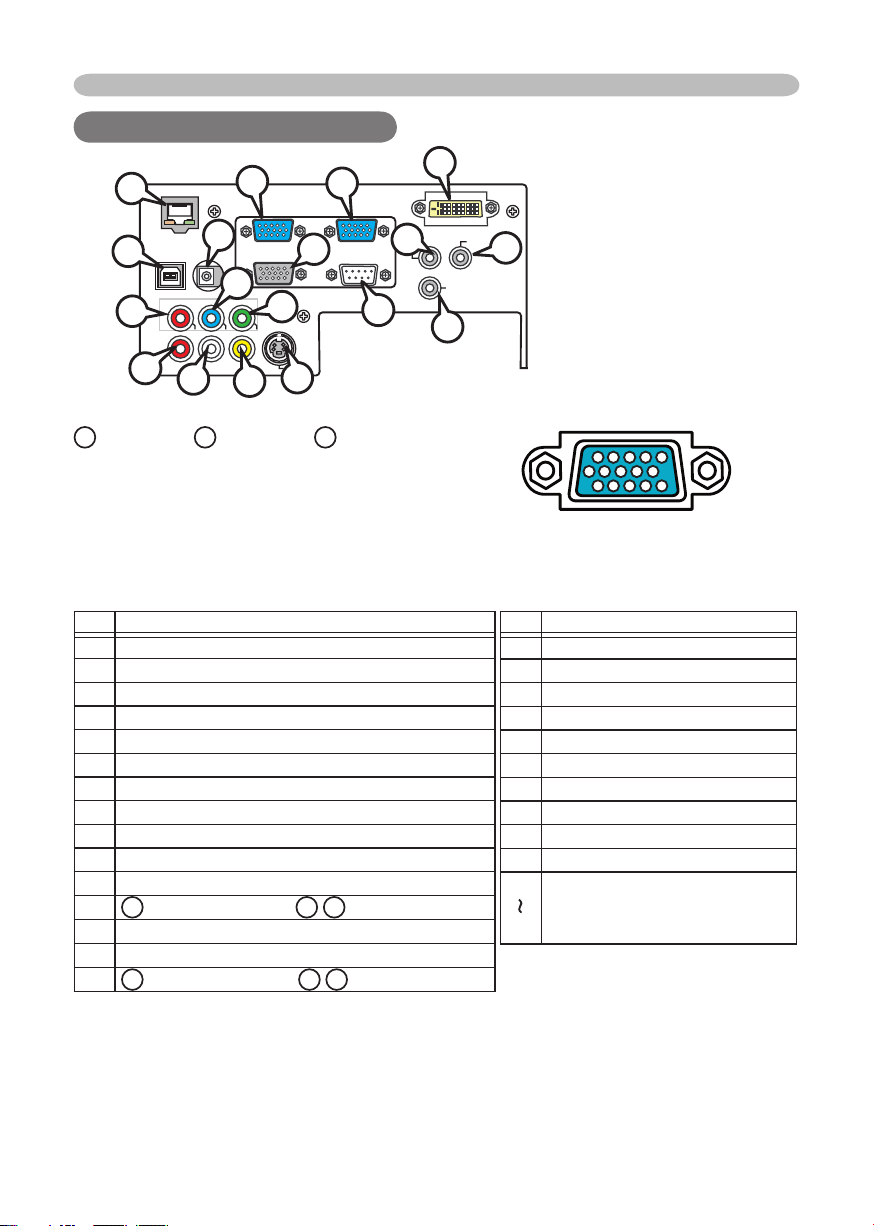
Connection to the ports
Connection to the ports
Connection to the ports
D
DVI-D
AUDIO-OUT
AUDIO-IN
L
REMOTE
CONTROL
R
M
11 12 13 14 15
6 7 8 9 10
1 2 3 4 5
J
CR/P
DC OUT
R
A
RGB IN1 RGB IN2
Q
F
RGB OUT CONTROL
Y
CB/P
B
VIDEO
I
E
P
LAN
O
USB
COMPONENT VIDEO
G
R-AUDIO IN-L
K
A
RGB IN 1, BRGB IN 2, CRGB OUT
S-VIDEO
H
B
C
N
D-sub 15pin mini shrink jack
• Video signal: RGB separate, Analog, 0.7Vp-p,
75Ω terminated (positive)
• H/V. sync. Signal: TTL level (positive/negative)
• Composite sync. Signal: TTL level
At RGB signal At component video signal
Pin Signal
1
Video Red
2 Video Green
3 Video Blue
4 (No connection)
5 Ground
6 Ground Red
7 Ground Green
8 Ground Blue
9 (No connection)
10 Ground
11 (No connection)
A
12
: SDA (DDC data),
13
H. sync / Composite sync.
14
V. sync.
A
15
: SCL (DDC clock),
B
B
C
: (No connection)
/
C
: (No connection)
/
Pin Signal
1
CR/P
R
2
Y
3
CB/P
B
4
(No connection)
5
Ground
6
CR/PR Ground
7
Y Ground
8
CB/PB Ground
9
(No connection)
10
Ground
11
(No connection)
15
* except for RGB OUT.
3
Page 72
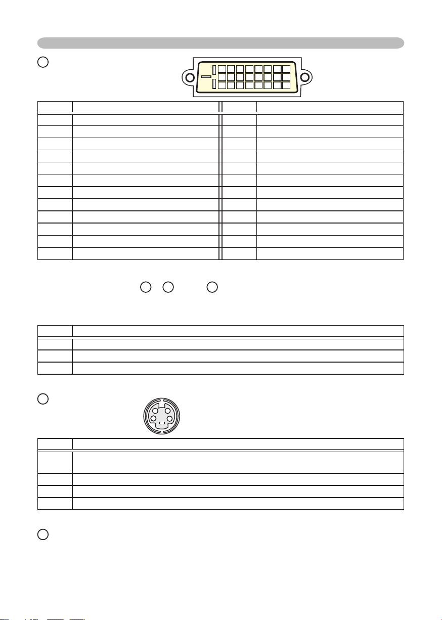
Connection to the ports
D
DVI -D
DVI-D jack (digital to digital)
24 23 22 21 20 19 18 17
16 15 14 13 12 11 10 9
8 7 6 5 4 3 2 1
Pin Signal Pin Signal
T.M.D.S. Data 2 - 13 -
1
T.M.D.S. Data 2 + 14 +5V Power
2
T.M.D.S. Data 2/4 Shield 15 Ground (+5V, Analog H/V.sync)
3
4
5
SCL (DDC Clock) 18 T.M.D.S. Data 0 +
6
SDA (DDC Data) 19 T.M.D.S. Data 0/5 Shield
7
Analog V. sync 20 -
8
T.M.D.S. Data 1 - 21 -
9
T.M.D.S. Data 1 + 22 T.M.D.S. Clock Shield
10
T.M.D.S. Data 1/3 Shield 23 T.M.D.S. Clock +
11
12
- 16 Hot-Plug Sense
- 17 T.M.D.S. Data 0 -
- 24 T.M.D.S. Clock -
COMPONENT VIDEO EY, FCB/PB, GCR/P
R
RCA jack x3
• System: 525i(480i), 525p(480p), 625i(576i), 750p(720p), 1125i(1080i)
Port Signal
Y Component video Y, 1.0±0.1Vp-p, 75Ω terminator with composite
B
/PBComponent video CB/PB, 0.7±0.1Vp-p, 75Ω terminator
C
R/PR
C
H
Mini DIN 4pin jack
Component video CR/PR, 0.7±0.1Vp-p, 75Ω terminator
S-VIDEO
1
2
3
4
Pin Signal
Color signal 0.286Vp-p (NTSC, burst), 75Ω terminator
1
Color signal 0.300Vp-p (PAL/SECAM, burst) 75Ω terminator
Brightness signal, 1.0Vp-p, 75Ω terminator
2
Ground
3
Ground
4
I
VIDEO
RCA jack
• System: NTSC, PAL, SECAM, PAL-M, PAL-N, NTSC4.43, PAL60
• 1.0±0.1Vp-p, 75Ω terminator
4
Page 73
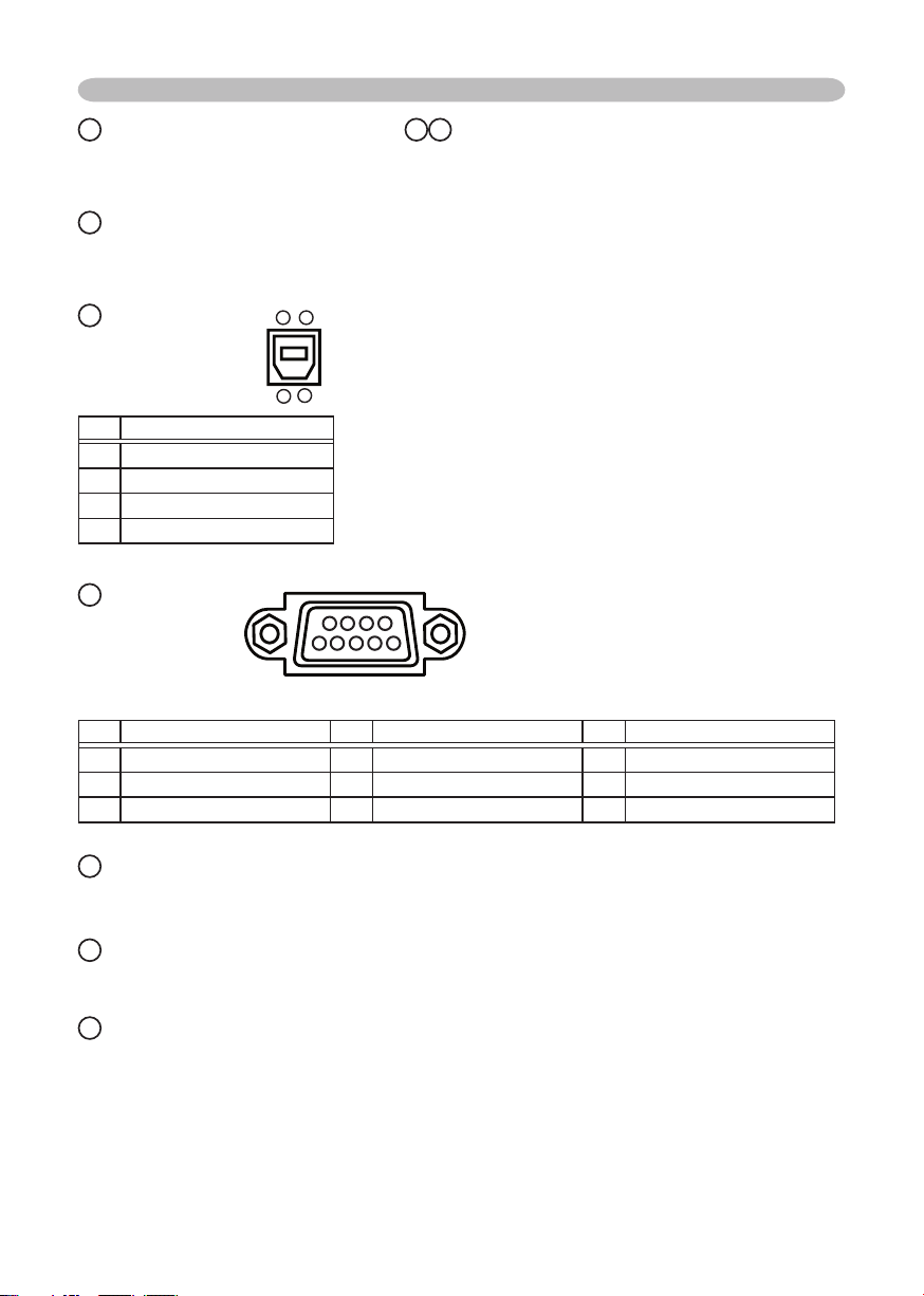
Connection to the ports
L
AUDIO IN (
Ø3.5 stereo mini jack),
J K
AUDIO INL/R (RCA jack)
• 200mVrms(max.) 50kΩ termination
M
AUDIO OUT (
Ø3.5 stereo mini jack)
• 200mVrms(max.) 1kΩ output impedance
O
USB
34
USB B type jack
2
1
Pin Signal
1 +5V
2 - Data
3 + Data
4 Ground
N
CONTROL
D-sub 9pin plug
9 8 7 6
5 4 3 2 1
• About the details of RS-232C communication, please refer to the following page.
Pin Signal Pin Signal Pin Signal
1 (No connection) 4 (No connection) 7 RTS
2 RD 5 Ground 8 CTS
3 TD 6 (No connection) 9 (No connection)
P
AN
L
RJ45 jack
Q
DC OUT
DC5V/1.5A(max.)
R
WIRED REMOTE
Ø3
.5mm Stereo Mini jack
• To be connected with the remote control that came with the projector.
5
Page 74
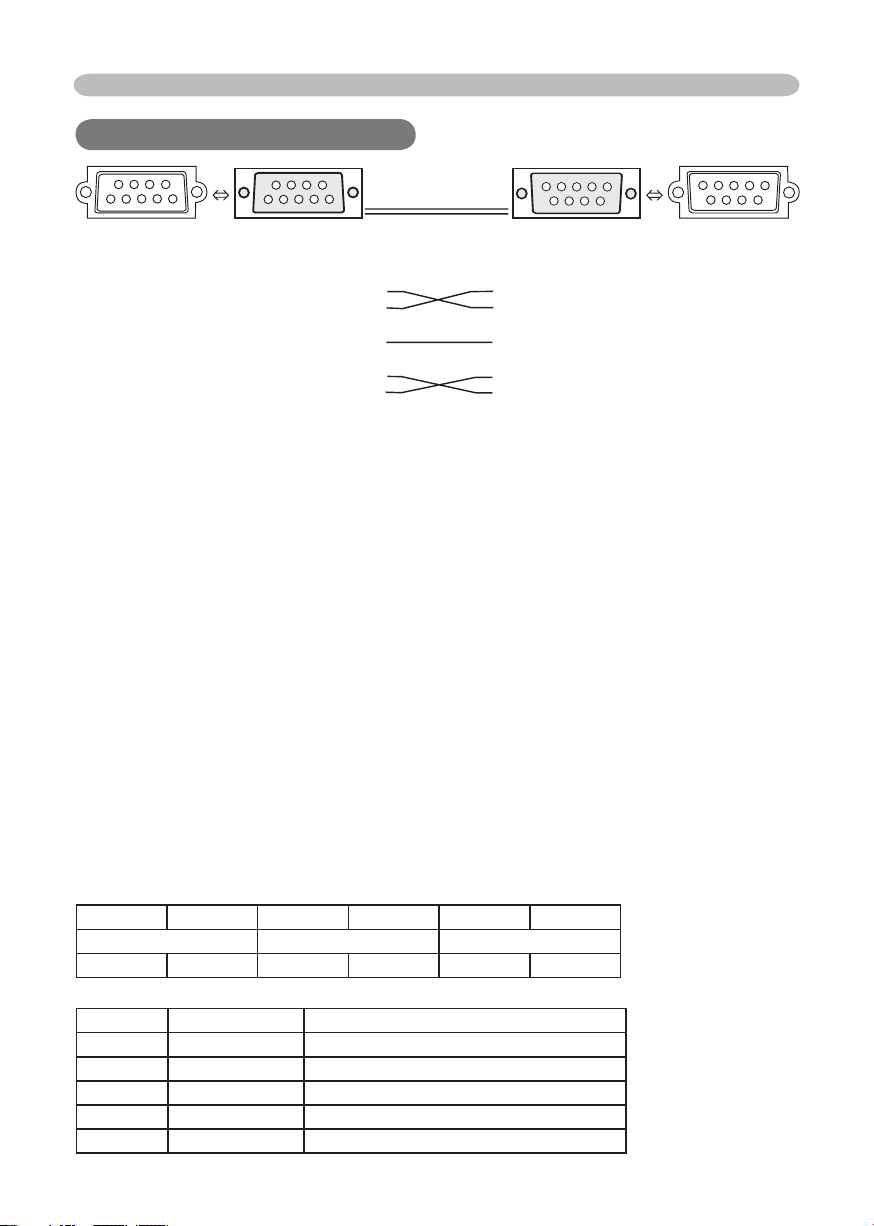
RS-232C Communication
RS-232C Communication
RS-232C Communication
89
67
123
4
5
CONTROL port RS-232C cable (Cross) RS-232C port
of the projector of the computer
RD (2) (2) RD
TD (3) (3) TD
- (4) (4) DTR
GND (5) (5) GND
- (6) (6) DSR
RTS (7) (7) RTS
CTS (8) (8) DTS
- (9) (9) RI
- (1) (1) CD
12345
6
789
Connecting the cable
Turn off the projector and the computer.
1.
Connect the CONTROL port of the projector with a RS-232C port of
2.
the computer by a RS-232C cable (cross). Use the cable that fulfills the
specifi cation shown in the previous page.
Turn the computer on, and after the computer has started up turn the
3.
projector on.
Communications setting
19200bps, 8N1
1. Protocol
Consist of header (7 bytes) + command data (6 bytes).
2. Header
BE + EF + 03 + 06 + 00 + CRC_low + CRC_high
CRC_low : Lower byte of CRC fl ag for command data
CRC_high : Upper byte of CRC fl ag for command data
3. Command data
Command data chart
byte_0 byte_1 byte_2 byte_3 byte_4 byte_5
Action Type Setting code
low high low high low high
Action (byte_0 - 1)
Action Classifi cation Content
1 SET Change setting to desired value.
2 GET Read projector internal setup value.
4 INCREMENT Increment setup value by 1.
5 DECREMENT Decrement setup value by 1.
6 EXECUTE Run a command.
6
Page 75

RS-232C Communication (continued)
Requesting projector status (Get command)
(1) Send the request code Header + Command data (‘02H’+‘00H’+ type (2 bytes)+
‘00H’ +‘00H’) from the computer to the projector.
(2) The projector returns the response code ‘1DH’+ data (2 bytes) to the computer.
Changing the projector settings (Set command)
(1) Send the setting code Header + Command data (‘01H’+‘00H’+ type (2 bytes) +
setting code (2 bytes)) from the computer to the projector.
(2) The projector changes the setting based on the above setting code.
(3) The projector returns the response code ‘06H’ to the computer.
Using the projector default settings (Reset Command)
(1) The computer sends the default setting code Header + Command data (‘06H’+
‘00H’ + type (2 bytes) +‘00H’+‘00H’) to the projector.
(2) The projector changes the specifi ed setting to the default value.
(3) The projector returns the response code ‘06H’ to the computer.
Increasing the projector setting value (Increment command)
(1) The computer sends the increment code Header + Command data (‘04H’+
‘00H’+ type (2 bytes) +‘00H’+‘00H’) to the projector.
(2) The projector in creases the setting value on the above setting code.
(3) The projector returns the response code ‘06H’ to the computer.
Decreasing the projector setting value (Decrement command)
(1) The computer sends the decrement code Header + Command data (‘05H’+
‘00H’+ type (2 bytes) +‘00H’ + ‘00H’) to the projector.
(2) The projector decreases the setting value on the above setting code.
(3) The projector returns the response code ‘06H’ to the computer.
When the projector cannot understand the received command
When the projector cannot understand the received command, the error code ‘15H’
is sent back to the computer.
Sometimes the projector cannot properly receive the command. In such a
case, the command is not executed and the error code ‘15H’ is sent back to the
computer. If this error code is returned, send the same command again.
When the projector cannot execute the received command.
When the projector cannot execute the received command, the error code ‘1cH’
+ ‘xxxxH’ is sent back to the computer. When the data length is greater than
indicated by the data length code, the projector ignore the excess data code.
Conversely when the data length is shorter than indicated by the data length
code, an error code will be returned to the computer.
NOTE • Operation cannot be guaranteed when the projector receives an undefi ned
command or data.
• Provide an interval of at least 40ms between the response code and any other code.
• The projector outputs test data when the power supply is switched ON, and when the
lamp is lit. Ignore this data.
• Commands are not accepted during warm-up.
7
Page 76
RS-232C Communication (continued)
RS-232C Communication (continued)
Names Operation Type Header
Power Set Turn off BE EF 03 06 00 2A D3 01 00 00 60 00 00
Turn on BE EF 03 06 00 BA D2 01 00 00 60 01 00
Get BE EF 03 06 00 19 D3 02 00 00 60 00 00
(Example return)
00 00 01 00 02 00
Input Source Set DVI BE EF 03 06 00 0E D2 01 00 00 20 03 00
RGB IN 1 BE EF 03 06 00 FE D2 01 00 00 20 00 00
RGB IN 2 BE EF 03 06 00 3E D0 01 00 00 20 04 00
VIDEO BE EF 03 06 00 6E D3 01 00 00 20 01 00
S-VIDEO BE EF 03 06 00 9E D3 01 00 00 20 02 00
COMPONENT BE EF 03 06 00 AE D1 01 00 00 20 05 00
Get BE EF 03 06 00 CD D2 02 00 00 20 00 00
Error Status Get BE EF 03 06 00 D9 D8 02 00 20 60 00 00
BRIGHT Get BE EF 03 06 00 89 D2 02 00 03 20 00 00
Increment BE EF 03 06 00 EF D2 04 00 03 20 00 00
Decrement BE EF 03 06 00 3E D3 05 00 03 20 00 00
BRIGHT Reset Execute BE EF 03 06 00 58 D3 06 00 00 70 00 00
CONTRAST Get BE EF 03 06 00 FD D3 02 00 04 20 00 00
Increment BE EF 03 06 00 9B D3 04 00 04 20 00 00
Decrement BE EF 03 06 00 4A D2 05 00 04 20 00 00
CONTRAST Reset Execute BE EF 03 06 00 A4 D2 06 00 01 70 00 00
MODE Set NORMAL BE EF 03 06 00 23 F6 01 00 BA 30 00 00
CINEMA BE EF 03 06 00 B3 F7 01 00 BA 30 01 00
DYNAMIC BE EF 03 06 00 E3 F4 01 00 BA 30 04 00
Get BE EF 03 06 00 10 F6 02 00 BA 30 00 00
GAMMA Set #1 DEFAULT BE EF 03 06 00 07 E9 01 00 A1 30 20 00
#1 CUSTOM BE EF 03 06 00 07 FD 01 00 A1 30 10 00
#2 DEFAULT BE EF 03 06 00 97 E8 01 00 A1 30 21 00
#2 CUSTOM BE EF 03 06 00 97 FC 01 00 A1 30 11 00
#3 DEFAULT BE EF 03 06 00 67 E8 01 00 A1 30 22 00
#3 CUSTOM BE EF 03 06 00 67 FC 01 00 A1 30 12 00
Get BE EF 03 06 00 F4 F0 02 00 A1 30 00 00
(Off) (On) (Cool down)
(Example return)
00 00 01 00 02 00 03 00
(Normal) (Cover error) (Fan error) (Lamp error)
04 00 05 00 06 00 07 00
(Temp error) (Air fl ow error) (Lamp time error) (Cool error)
08 00
(Filter error) (Filter missing error) (Inner Sencer error)
(Example return)
00 00 01 00 04 00 10 00
(Normal) (Cinema) (Dynamic) (Custom)
CRC Action Type Setting Code
09 00 10 00
Command Data
8
Page 77
RS-232C Communication (continued)
RS-232C Communication (continued)
Names Operation Type Header
User Gamma Pattern Set Off BE EF 03 06 00 FB FA 01 00 80 30 00 00
9 step gray scale BE EF 03 06 00 6B FB 01 00 80 30 01 00
15 steps gray scale BE EF 03 06 00 9B FB 01 00 80 30 02 00
Ramp BE EF 03 06 00 0B FA 01 00 80 30 03 00
Get BE EF 03 06 00 C8 FA 02 00 80 30 00 00
User Gamma Point 1 Get BE EF 03 06 00 08 FE 02 00 90 30 00 00
Increment BE EF 03 06 00 6E FE 04 00 90 30 00 00
Decrement BE EF 03 06 00 BF FF 05 00 90 30 00 00
User Gamma Point 2 Get BE EF 03 06 00 F4 FF 02 00 91 30 00 00
Increment BE EF 03 06 00 92 FF 04 00 91 30 00 00
Decrement BE EF 03 06 00 43 FE 05 00 91 30 00 00
User Gamma Point 3 Get BE EF 03 06 00 B0 FF 02 00 92 30 00 00
Increment BE EF 03 06 00 D6 FF 04 00 92 30 00 00
Decrement BE EF 03 06 00 07 FE 05 00 92 30 00 00
User Gamma Point 4 Get BE EF 03 06 00 4C FE 02 00 93 30 00 00
Increment BE EF 03 06 00 2A FE 04 00 93 30 00 00
Decrement BE EF 03 06 00 FB FF 05 00 93 30 00 00
User Gamma Point 5 Get BE EF 03 06 00 38 FF 02 00 94 30 00 00
Increment BE EF 03 06 00 5E FF 04 00 94 30 00 00
Decrement BE EF 03 06 00 8F FE 05 00 94 30 00 00
User Gamma Point 6 Get BE EF 03 06 00 C4 FE 02 00 95 30 00 00
Increment BE EF 03 06 00 A2 FE 04 00 95 30 00 00
Decrement BE EF 03 06 00 73 FF 05 00 95 30 00 00
User Gamma Point 7 Get BE EF 03 06 00 80 FE 02 00 96 30 00 00
Increment BE EF 03 06 00 E6 FE 04 00 96 30 00 00
Decrement BE EF 03 06 00 37 FF 05 00 96 30 00 00
User Gamma Point 8 Get BE EF 03 06 00 7C FF 02 00 97 30 00 00
Increment BE EF 03 06 00 1A FF 04 00 97 30 00 00
Decrement BE EF 03 06 00 CB FE 05 00 97 30 00 00
COLOR TEMP Set LOW BE EF 03 06 00 6B F4 01 00 B0 30 01 00
MIDDLE BE EF 03 06 00 9B F4 01 00 B0 30 02 00
HIGH BE EF 03 06 00 0B F5 01 00 B0 30 03 00
CUSTOM BE EF 03 06 00 3B F8 01 00 B0 30 10 00
Get BE EF 03 06 00 C8 F5 02 00 B0 30 00 00
COLOR TEMP GAIN R Get BE EF 03 06 00 34 F4 02 00 B1 30 00 00
Increment BE EF 03 06 00 52 F4 04 00 B1 30 00 00
Decrement BE EF 03 06 00 83 F5 05 00 B1 30 00 00
CRC Action Type Setting Code
Command Data
9
Page 78
RS-232C Communication (continued)
RS-232C Communication (continued)
Names Operation Type Header
COLOR TEMP GAIN G Get BE EF 03 06 00 70 F4 02 00 B2 30 00 00
Increment BE EF 03 06 00 16 F4 04 00 B2 30 00 00
Decrement BE EF 03 06 00 C7 F5 05 00 B2 30 00 00
COLOR TEMP GAIN B Get BE EF 03 06 00 8C F5 02 00 B3 30 00 00
Increment BE EF 03 06 00 EA F5 04 00 B3 30 00 00
Decrement BE EF 03 06 00 3B F4 05 00 B3 30 00 00
COLOR TEMP
OFFSET R
COLOR TEMP
OFFSET G
COLOR TEMP
OFFSET B
COLOR Get BE EF 03 06 00 B5 72 02 00 02 22 00 00
COLOR Reset Execute BE EF 03 06 00 80 D0 06 00 0A 70 00 00
TINT Get BE EF 03 06 00 49 73 02 00 03 22 00 00
TINT Reset Execute BE EF 03 06 00 7C D1 06 00 0B 70 00 00
SHARPNESS Get BE EF 03 06 00 F1 72 02 00 01 22 00 00
SHARPNESS Reset Execute BE EF 03 06 00 C4 D0 06 00 09 70 00 00
MY MEMORY Load Set 1 BE EF 03 06 00 0E D7 01 00 14 20 00 00
MY MEMORY Save Set 1 BE EF 03 06 00 F2 D6 01 00 15 20 00 00
Get BE EF 03 06 00 04 F5 02 00 B5 30 00 00
Increment BE EF 03 06 00 62 F5 04 00 B5 30 00 00
Decrement BE EF 03 06 00 B3 F4 05 00 B5 30 00 00
Get BE EF 03 06 00 40 F5 02 00 B6 30 00 00
Increment BE EF 03 06 00 26 F5 04 00 B6 30 00 00
Decrement BE EF 03 06 00 F7 F4 05 00 B6 30 00 00
Get BE EF 03 06 00 BC F4 02 00 B7 30 00 00
Increment BE EF 03 06 00 DA F4 04 00 B7 30 00 00
Decrement BE EF 03 06 00 0B F5 05 00 B7 30 00 00
Increment BE EF 03 06 00 D3 72 04 00 02 22 00 00
Decrement BE EF 03 06 00 02 73 05 00 02 22 00 00
Increment BE EF 03 06 00 2F 73 04 00 03 22 00 00
Decrement BE EF 03 06 00 FE 72 05 00 03 22 00 00
Increment BE EF 03 06 00 97 72 04 00 01 22 00 00
Decrement BE EF 03 06 00 46 73 05 00 01 22 00 00
2 BE EF 03 06 00 9E D6 01 00 14 20 01 00
3 BE EF 03 06 00 6E D6 01 00 14 20 02 00
4 BE EF 03 06 00 FE D7 01 00 14 20 03 00
2 BE EF 03 06 00 62 D7 01 00 15 20 01 00
3 BE EF 03 06 00 92 D7 01 00 15 20 02 00
4 BE EF 03 06 00 02 D6 01 00 15 20 03 00
CRC Action Type Setting Code
Command Data
10
Page 79
RS-232C Communication (continued)
RS-232C Communication (continued)
Names Operation Type Header
PROGRESSIVE Set TURN OFF BE EF 03 06 00 4A 72 01 00 07 22 00 00
TV BE EF 03 06 00 DA 73 01 00 07 22 01 00
FILM BE EF 03 06 00 2A 73 01 00 07 22 02 00
Get BE EF 03 06 00 79 72 02 00 07 22 00 00
3D-YCS Set TURN OFF BE EF 03 06 00 E6 70 01 00 0A 22 00 00
NORMAL BE EF 03 06 00 76 71 01 00 0A 22 01 00
STILL IMAGE BE EF 03 06 00 86 71 01 00 0A 22 02 00
Get BE EF 03 06 00 D5 70 02 00 0A 22 00 00
VIDEO NR Set LOW BE EF 03 06 00 26 72 01 00 06 22 01 00
MIDDLE BE EF 03 06 00 D6 72 01 00 06 22 02 00
HIGH BE EF 03 06 00 46 73 01 00 06 22 03 00
Get BE EF 03 06 00 85 73 02 00 06 22 00 00
ASPECT Set 4:3 BE EF 03 06 00 9E D0 01 00 08 20 00 00
16:9 BE EF 03 06 00 0E D1 01 00 08 20 01 00
SMALL BE EF 03 06 00 FE D1 01 00 08 20 02 00
NORMAL BE EF 03 06 00 5E DD 01 00 08 20 10 00
Get BE EF 03 06 00 AD D0 02 00 08 20 00 00
OVER SCAN Get BE EF 03 06 00 91 70 02 00 09 22 00 00
Increment BE EF 03 06 00 F7 70 04 00 09 22 00 00
Decrement BE EF 03 06 00 26 71 05 00 09 22 00 00
OVER SCAN Reset Execute BE EF 03 06 00 EC D9 06 00 27 70 00 00
V POSITION Get BE EF 03 06 00 0D 83 02 00 00 21 00 00
Increment BE EF 03 06 00 6B 83 04 00 00 21 00 00
Decrement BE EF 03 06 00 BA 82 05 00 00 21 00 00
V POSITION Reset Execute BE EF 03 06 00 E0 D2 06 00 02 70 00 00
H POSITION Get BE EF 03 06 00 F1 82 02 00 01 21 00 00
Increment BE EF 03 06 00 97 82 04 00 01 21 00 00
Decrement BE EF 03 06 00 46 83 05 00 01 21 00 00
H POSITION Reset Execute BE EF 03 06 00 1C D3 06 00 03 70 00 00
H PHASE Get BE EF 03 06 00 49 83 02 00 03 21 00 00
Increment BE EF 03 06 00 2F 83 04 00 03 21 00 00
Decrement BE EF 03 06 00 FE 82 05 00 03 21 00 00
H SIZE Get BE EF 03 06 00 B5 82 02 00 02 21 00 00
Increment BE EF 03 06 00 D3 82 04 00 02 21 00 00
Decrement BE EF 03 06 00 02 83 05 00 02 21 00 00
H SIZE Reset Execute BE EF 03 06 00 68 D2 06 00 04 70 00 00
AUTO ADJUST Execute BE EF 03 06 00 91 D0 06 00 0A 20 00 00
CRC Action Type Setting Code
Command Data
11
Page 80
RS-232C Communication (continued)
RS-232C Communication (continued)
Names Operation Type Header
COLOR SPACE Set AUTO BE EF 03 06 00 0E 72 01 00 04 22 00 00
RGB BE EF 03 06 00 9E 73 01 00 04 22 01 00
SMPTE240 BE EF 03 06 00 6E 73 01 00 04 22 02 00
REC709 BE EF 03 06 00 FE 72 01 00 04 22 03 00
REC601 BE EF 03 06 00 CE 70 01 00 04 22 04 00
Get BE EF 03 06 00 3D 72 02 00 04 22 00 00
COMPONENT Set COMPONENT BE EF 03 06 00 4A D7 01 00 17 20 00 00
SCART RGB BE EF 03 06 00 DA D6 01 00 17 20 01 00
Get BE EF 03 06 00 79 D7 02 00 17 20 00 00
VIDEO FORMAT Set AUTO BE EF 03 06 00 9E 75 01 00 00 22 0A 00
NTSC BE EF 03 06 00 FE 71 01 00 00 22 04 00
PAL BE EF 03 06 00 6E 70 01 00 00 22 05 00
SECAM BE EF 03 06 00 6E 75 01 00 00 22 09 00
NTSC4.43 BE EF 03 06 00 5E 72 01 00 00 22 02 00
M-PAL BE EF 03 06 00 FE 74 01 00 00 22 08 00
N-PAL BE EF 03 06 00 0E 71 01 00 00 22 07 00
Get BE EF 03 06 00 0D 73 02 00 00 22 00 00
DVI Set DVD BE EF 03 06 00 3E D9 01 00 20 20 00 00
COMPUTER BE EF 03 06 00 AE D8 01 00 20 20 01 00
Get BE EF 03 06 00 0D D9 02 00 20 20 00 00
KEYSTONE V Get BE EF 03 06 00 B9 D3 02 00 07 20 00 00
Increment BE EF 03 06 00 DF D3 04 00 07 20 00 00
Decrement BE EF 03 06 00 0E D2 05 00 07 20 00 00
KEYSTONE V Reset Execute BE EF 03 06 00 08 D0 06 00 0C 70 00 00
KEYSTONE H Get BE EF 03 06 00 E9 D0 02 00 0B 20 00 00
Increment BE EF 03 06 00 8F d0 04 00 0B 20 00 00
Decrement BE EF 03 06 00 5E D1 05 00 0B 20 00 00
KEYSTONE H Reset Execute BE EF 03 06 00 98 D8 06 00 20 70 00 00
WHISPER Set NORMAL BE EF 03 06 00 3B 23 01 00 00 33 00 00
WHISPER BE EF 03 06 00 AB 22 01 00 00 33 01 00
Get BE EF 03 06 00 08 23 02 00 00 33 00 00
MIRROR Set NORMAL BE EF 03 06 00 C7 D2 01 00 01 30 00 00
H:INVERT BE EF 03 06 00 57 D3 01 00 01 30 01 00
V:INVERT BE EF 03 06 00 A7 D3 01 00 01 30 02 00
H&V:INVERT BE EF 03 06 00 37 D2 01 00 01 30 03 00
Get BE EF 03 06 00 F4 D2 02 00 01 30 00 00
VOLUME Get BE EF 03 06 00 31 D3 02 00 01 20 00 00
Increment BE EF 03 06 00 57 D3 04 00 01 20 00 00
Decrement BE EF 03 06 00 86 D2 05 00 01 20 00 00
CRC Action Type Setting Code
Command Data
12
Page 81
RS-232C Communication (continued)
RS-232C Communication (continued)
Names Operation Type Header
MUTE Set TURN OFF BE EF 03 06 00 46 D3 01 00 02 20 00 00
TURN ON BE EF 03 06 00 D6 D2 01 00 02 20 01 00
Get BE EF 03 06 00 75 D3 02 00 02 20 00 00
STEREO Set MONO BE EF 03 06 00 92 D4 01 00 1D 20 00 00
STEREO BE EF 03 06 00 02 D5 01 00 1D 20 01 00
Get BE EF 03 06 00 A1 D4 02 00 1D 20 00 00
IR REMOTE Front Set Off BE EF 03 06 00 FF 32 01 00 00 26 00 00
On BE EF 03 06 00 6F 33 01 00 00 26 01 00
Get BE EF 03 06 00 CC 32 02 00 00 26 00 00
IR REMOTE Top Set Off BE EF 03 06 00 47 33 01 00 02 26 00 00
On BE EF 03 06 00 D7 32 01 00 02 26 01 00
Get BE EF 03 06 00 74 33 02 00 02 26 00 00
LANGUAGE Set ENGLISH BE EF 03 06 00 F7 D3 01 00 05 30 00 00
FRANÇAIS BE EF 03 06 00 67 D2 01 00 05 30 01 00
DEUTSCH BE EF 03 06 00 97 D2 01 00 05 30 02 00
ESPAÑOL BE EF 03 06 00 07 D3 01 00 05 30 03 00
ITALIANO BE EF 03 06 00 37 D1 01 00 05 30 04 00
NORSK BE EF 03 06 00 A7 D0 01 00 05 30 05 00
NEDERLANDS BE EF 03 06 00 57 D0 01 00 05 30 06 00
PORTUGUÊS BE EF 03 06 00 C7 D1 01 00 05 30 07 00
BE EF 03 06 00 37 D4 01 00 05 30 08 00
BE EF 03 06 00 A7 D5 01 00 05 30 09 00
BE EF 03 06 00 57 D5 01 00 05 30 0A 00
SVENSKA BE EF 03 06 00 C7 D4 01 00 05 30 0B 00
PУCCKИЙ BE EF 03 06 00 F7 D6 01 00 05 30 0C 00
SUOMI BE EF 03 06 00 67 D7 01 00 05 30 0D 00
POLSKI BE EF 03 06 00 97 D7 01 00 05 30 0E 00
TÜRKÇE BE EF 03 06 00 07 D6 01 00 05 30 0F 00
BE EF 03 06 00 37 DE 01 00 05 30 10 00
Get BE EF 03 06 00 C4 D3 02 00 05 30 00 00
MENU POSITION H Get BE EF 03 06 00 04 D7 02 00 15 30 00 00
Increment BE EF 03 06 00 62 D7 04 00 15 30 00 00
Decrement BE EF 03 06 00 B3 D6 05 00 15 30 00 00
MENU POSITION H
Reset
MENU POSITION V Get BE EF 03 06 00 40 D7 02 00 16 30 00 00
MENU POSITION V
Reset
Execute BE EF 03 06 00 DC C6 06 00 43 70 00 00
Increment BE EF 03 06 00 26 D7 04 00 16 30 00 00
Decrement BE EF 03 06 00 F7 D6 05 00 16 30 00 00
Execute BE EF 03 06 00 A8 C7 06 00 44 70 00 00
CRC Action Type Setting Code
Command Data
13
Page 82
RS-232C Communication (continued)
RS-232C Communication (continued)
Names Operation Type Header
OSD BRIGHT Get BE EF 03 06 00 A8 D5 02 00 18 30 00 00
Increment BE EF 03 06 00 CE D5 04 00 18 30 00 00
Decrement BE EF 03 06 00 1F D4 05 00 18 30 00 00
BLANK Set My Screen BE EF 03 06 00 FB CA 01 00 00 30 20 00
ORIGINAL BE EF 03 06 00 FB E2 01 00 00 30 40 00
BLUE BE EF 03 06 00 CB D3 01 00 00 30 03 00
WHITE BE EF 03 06 00 6B D0 01 00 00 30 05 00
BLACK BE EF 03 06 00 9B D0 01 00 00 30 06 00
Get BE EF 03 06 00 08 D3 02 00 00 30 00 00
BLANK On/Off Set TURN OFF BE EF 03 06 00 FB D8 01 00 20 30 00 00
TURN ON BE EF 03 06 00 6B D9 01 00 20 30 01 00
Get BE EF 03 06 00 C8 D8 02 00 20 30 00 00
START UP Set My Screen BE EF 03 06 00 CB CB 01 00 04 30 20 00
ORIGINAL BE EF 03 06 00 0B D2 01 00 04 30 00 00
TURN OFF BE EF 03 06 00 9B D3 01 00 04 30 01 00
Get BE EF 03 06 00 38 D2 02 00 04 30 00 00
My Screen LOCK Set TURN OFF BE EF 03 06 00 3B EF 01 00 C0 30 00 00
TURN ON BE EF 03 06 00 AB EE 01 00 C0 30 01 00
Get BE EF 03 06 00 08 EF 02 00 C0 30 00 00
Message Set TURN OFF BE EF 03 06 00 8F D6 01 00 17 30 00 00
TURN ON BE EF 03 06 00 1F D7 01 00 17 30 01 00
Get BE EF 03 06 00 BC D6 02 00 17 30 00 00
ONE TOUCH Set
AUTO KEYSTONE V EXECUTE BE EF 03 06 00 E5 D1 06 00 0D 20 00 00
AUTO SEARCH Set TURN OFF BE EF 03 06 00 B6 D6 01 00 16 20 00 00
AUTO POWER OFF Get BE EF 03 06 00 08 86 02 00 10 31 00 00
LAMP TIME Get BE EF 03 06 00 C2 FF 02 00 90 10 00 00
LAMP TIME Reset Execute BE EF 03 06 00 58 DC 06 00 30 70 00 00
FILTER TIME Get BE EF 03 06 00 C2 F0 02 00 A0 10 00 00
FILER TIME Reset Execute BE EF 03 06 00 98 C6 06 00 40 70 00 00
MAGNIFY Get BE EF 03 06 00 7C D2 02 00 07 30 00 00
FREEZE Set NORMAL BE EF 03 06 00 83 D2 01 00 02 30 00 00
KEYSTONE V TURN OFF
KEYSTONE V TURN ON
Get BE EF 03 06 00 25 D0 02 00 0E 20 00 00
TURN ON BE EF 03 06 00 26 D7 01 00 16 20 01 00
Get BE EF 03 06 00 85 D6 02 00 16 20 00 00
Increment BE EF 03 06 00 6E 86 04 00 10 31 00 00
Decrement BE EF 03 06 00 BF 87 05 00 10 31 00 00
Increment BE EF 03 06 00 1A D2 04 00 07 30 00 00
Decrement BE EF 03 06 00 CB D3 05 00 07 30 00 00
FREEZE BE EF 03 06 00 13 D3 01 00 02 30 01 00
Get BE EF 03 06 00 B0 D2 02 00 02 30 00 00
BE EF 03 06 00 16 D0 01 00 0E 20 00 00
BE EF 03 06 00 86 D1 01 00 0E 20 01 00
CRC Action Type Setting Code
Command Data
14
Page 83

DUKANE CORPORATION
FIVE-YEAR LIMITED WARRANTY
This Dukane projector is warranted to the original purchaser for a period of five (5) years from
the original purchase date – in normal operating conditions – against defects in material and
workmanship . DUKANE CORPORATION EXPRESSLY DISCLAIMS ALL OTHER
WARRANTIES OF MERCHANTABILITY AND FITNESS FOR A PARTICULAR PURPOSE.
DURING THE WARRANTY PERIOD, DUKANE CORPORATION’S LIABILITY FOR ANY
DEFECTIVE PRODUCT (except for the lamp, which is subject to whatever warranties the
manufacturer may provide) IS LIMITED TO THE REPAIR OR REPLACEMENT OF
PRODUCT AT DUKANE CORPORATION’S OPTION. REPLACEMENT PRODUCTS MAY
BE NEW OR USED (used units will not exceed hours of defective unit). The following are not
covered by the limited warranty and Dukane Corporation shall not be liable for:
1. Any product which is not distributed in the U.S.A. or Canada by Dukane Corporation or an
authorized dealer.
2. Normal decrease in lamp light output over time.
3. Damage, deterioration or malfunction resulting from:
• Accident, misuse, abuse, neglect, improper ventilation, fire, dust, smoke, water, lighting
or other acts of nature, unauthorized product modification, or failure to follow
instructions supplied with the product (including proper maintenance of air filters).
• Repair or attempted repair by anyone other than a Dukane Corporation authorized service
center.
• Any shipment of product (claims must be presented to the carrier).
• Removal or installation of the product.
• Any other causes which do not relate to a product defect.
• Use of the product beyond normal operating conditions. Normal operating conditions are
defined as product use not in excess of 8 hours per day and 260 days per year.
4. Cartons, carry cases, shipping cases, batteries, or any accessories used in connection with the
product.
5. Service required as a result of third party components.
6. Product used as commercial rental units
Dukane corporation will pay labor and material expenses for covered items, but Dukane
Corporation will not pay for the following:
1. Removal or installation charges.
2. Cost of technical adjustment, set-up, maintenance, or adjustment of user controls.
3. Payment of shipping and related charges incurred in returning the product for warranty
repair.
Dukane Corporation disclaims all liability for incidental or consequential damage of any kind,
including all damages arising out of any interruptions in operation of the product and all damages
to software.
No person, firm, or representative is authorized to assume any obligation or to make any warranty
on behalf of the Dukane Corporation other than as stated above.
Page 84

Dukane Corporation
Audio Visual Products Division
2900 Dukane Drive
St. Charles, IL 60174-3395
E-mail: [email protected]
Audio Visual Products
Phone: (630) 762-4040
Orders: (800) 676-2485
Fax: (630) 584-5156
Parts & Service: (800) 676-2487
Fax: (630) 584-0984
Part # 401-8915-00
 Loading...